SMATV Noise generator Ref. 5930
SMATV Noise generator Ref. 5930
SMATV Noise generator Ref. 5930

You also want an ePaper? Increase the reach of your titles
YUMPU automatically turns print PDFs into web optimized ePapers that Google loves.
<strong>SMATV</strong><br />
24<br />
<strong>Noise</strong> <strong>generator</strong><br />
<strong>Ref</strong>. <strong>5930</strong><br />
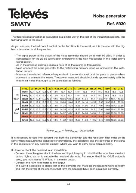
The theoretical attenuation is calculated in a similar way in the rest of the installation sockets. The<br />
following table is the result:<br />
As you can see, the bedroom 2 socket on the 2nd floor is the worst, as it is the one with the highest<br />
attenuation in all frequencies.<br />
- The signal power at the output of the noise <strong>generator</strong> should be at least 60 dBuV in order to<br />
compensate for the 22 dB attenuation undergone in the high frequencies in the installation's<br />
worst socket.<br />
- As in the previous example, make a note of all the reference frequencies.<br />
- Next, connect the noise <strong>generator</strong> to the distribution network input, as indicated in the installation<br />
picture.<br />
- Measure the selected reference frequencies in the worst socket or at the place or places where<br />
you want to evaluate the losses. The power measured should coincide approximately with the<br />
theoretical value that ought to be calculated as follows:<br />
Freq. 20 55.25 99 120 175.25 274.25 210 471.25 607.25 855.25 950 1350 1750 2150<br />
Bed1 12.1 12.1 12.6 12.6 12.6 13.4 13.4 13.8 13.8 14.1 18.3 18.6 18.9 19.2<br />
1st Study 12.1 12.1 12.6 12.6 12.6 13.4 13.4 13.8 13.8 14.1 18.3 18.6 18.9 19.2<br />
floor Bed2 12.1 12.1 12.6 12.6 12.6 13.56 13.56 14.04 14.04 14.4 18.66 19.11 19.47 19.83<br />
Bed3 12.1 12.1 12.6 12.6 12.6 13.64 13.64 14.16 14.16 14.55 18.93 19.32 19.71 20.10<br />
LivR1 13.6 13.6 13.6 13.6 13.6 14.24 14.24 14.56 14.56 14.8 17.94 18.68 19.42 20.66<br />
2nd LivR2 13.6 13.6 13.6 13.6 13.6 14.24 14.24 14.56 14.56 14.8 17.94 18.68 19.42 20.66<br />
floor Bed1 13.6 13.6 13.6 13.6 13.6 14.32 14.32 14.68 14.68 14.95 18.12 18.89 19.66 20.93<br />
Bed2 13.6 13.6 13.6 13.6 13.6 14.64 14.64 15.16 15.16 15.55 18.84 19.73 20.62 22.01<br />
Kitch 13.6 13.6 13.6 13.6 13.6 14.32 14.32 14.68 14.68 14.95 18.12 18.89 19.66 20.93<br />
Power output = Power input - Attenuation<br />
It is necessary to take into account that both the bandwidth and the resolution filter must be the<br />
same when measuring the signal power provided by the <strong>generator</strong>, and the powering of the signal<br />
in the sockets (or in any network element where you wish to carry out a measurement).<br />
3.- How to check the headend in an installation:<br />
- Connect the noise <strong>generator</strong> to the headend input, keeping in mind that the input level must not<br />
be too high so as not to saturate the headend elements. Remember that if the -30dB output is<br />
used, you must use a 75 W load in the main output.<br />
- Connect the FSM field meter to the output<br />
- This way it is possible to check that all the elements that make up the headend work correctly,<br />
and that the levels of the channels that form the headend have been equalised correctly.