SMATV Noise generator Ref. 5930
SMATV Noise generator Ref. 5930
SMATV Noise generator Ref. 5930

Create successful ePaper yourself
Turn your PDF publications into a flip-book with our unique Google optimized e-Paper software.
<strong>SMATV</strong><br />
5<br />
3<br />
- 30 dB<br />
Generatore di Rumore<br />
15<br />
N o ise Ge n era tor<br />
Level Adx.<br />
<strong>Ref</strong>. <strong>5930</strong><br />
0 1<br />
8 2<br />
7 3<br />
6 5 4<br />
9<br />
0 - 10 dB<br />
5 - 2.150 MHz<br />
ON<br />
<strong>Noise</strong> <strong>generator</strong><br />
234796<br />
2<br />
<strong>Ref</strong>. <strong>5930</strong><br />
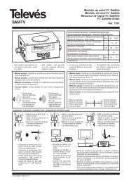
A device designed to carry out attenuation and flatness testing in F.I. satellite installations with no<br />
entry signal, connected to a Televés FSM or MTD series field strength meter.<br />
Equipped with a thumbwheel allowing the output level to be varied by 10 ± 2 dB in 10 steps<br />
1.- Normal signal output. Electrical connection from installation to power the simulator.<br />
2.- Output attenuated by 30 dB compared to output obtained in 1. If the attenuated output is used,<br />
the main output must be charged.<br />
3.- Thumbwheel to vary the output level in both connectors by 10 ± 2 dB.<br />
4.- LED indicator<br />
5.- Connector to provide external power to the simulator using the DC adaptor.<br />
Technical data<br />
Power supply (external or via coaxial cable) 12 ...... 18 V<br />
Consumption < = 2 W<br />
Output connector “F” female<br />
Frequency 5 - 2150 MHz<br />
Maximum output level 80 ± 3dBµV/3MHz<br />
Output level regulator 0 - 10 dB<br />
4<br />
1<br />
ENGLISH
<strong>SMATV</strong><br />
Checking an installation<br />
5498<br />
Power supply<br />
PWR<br />
<strong>Noise</strong><br />
<strong>generator</strong><br />
Generador ruido<br />
<strong>Noise</strong> Generator<br />
<strong>Ref</strong>. <strong>5930</strong><br />
Level Adx.<br />
5 - 2.150 MHz<br />
9<br />
0<br />
12<br />
-30 dB 8<br />
ON<br />
7 3<br />
6 5 4<br />
0 - 10 dB<br />
234796<br />
Verification of T03 headend<br />
C49 C52 C42 C61 C55 C58 C65-69<br />
5086<br />
TV antenna or<br />
cable signal<br />
Mixer<br />
TV socket<br />
16<br />
-30 dB<br />
Level Adx.<br />
9<br />
0<br />
1<br />
8 2<br />
7 3<br />
6 5 4<br />
0 - 10 dB<br />
Generador ruido<br />
<strong>Noise</strong> Generator<br />
<strong>Ref</strong>. <strong>5930</strong><br />
Measuring<br />
device signal<br />
input<br />
5 - 2.150 MHz<br />
ON<br />
234796<br />
<strong>Noise</strong> <strong>generator</strong><br />
<strong>Noise</strong><br />
<strong>generator</strong><br />
C55 C58<br />
C61<br />
<strong>Ref</strong>. <strong>5930</strong><br />
Measuring<br />
device signal<br />
input<br />
C65-69
<strong>SMATV</strong><br />
17<br />
<strong>Noise</strong> <strong>generator</strong><br />
<strong>Ref</strong>. <strong>5930</strong><br />
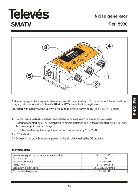
The noise <strong>generator</strong> can be powered by an mains adaptor, or by the meter via an RF cable. In order<br />
to do this simply select the pre-amplifier powering in the meter's corresponding menu.<br />
To access the pre-amplifier powering menu in the field strength meter, you can follow these steps:<br />
In the terrestrial band:<br />
CONFIG.<br />
MEASURE<br />
In the satellite band:<br />
CONFIG.<br />
MEASURE<br />
Or, press the fast button<br />
This will open the Powering window:<br />
PREAMPLIF.<br />
LNB &<br />
PREAMPLIF.<br />
It is advisable to select the power measurement in the FSM when working with the noise <strong>generator</strong>.<br />
Application examples:<br />
LNB<br />
A few applications of the noise <strong>generator</strong> are briefly explained below:<br />
1.- Checking the condition of a section of the cable before installing: By using the noise <strong>generator</strong><br />
and the FSM field meter it is possible to check the condition of a section of the cable<br />
before installing it.<br />
ENGLISH
<strong>SMATV</strong><br />
18<br />
<strong>Noise</strong> <strong>generator</strong><br />
<strong>Ref</strong>. <strong>5930</strong><br />
- Configure the FSM field meter to analyze mode, select Full Span and select the powering<br />
measurement.<br />
- Connect the noise <strong>generator</strong> to the FSM meter. Check that the generated noise spectrum<br />
is nearly flat. The longer the cable you are going to check, the bigger the powering<br />
produced by the noise <strong>generator</strong> should be. A small table with the recommended<br />
minimum powering, depending on the length of the cable to be checked, is shown<br />
below (the wire T100 -ref.2141 has been used as an example).<br />
Length of cable in metres (T100) Minimum output powering of the noise <strong>generator</strong> (dBuV)<br />
10 43<br />
25 47<br />
50 55<br />
75 62<br />
100 70<br />
150 80<br />
Select the adequate reference level on the meter. Note down the measurement of the powering in<br />
several frequencies along the terrestrial band, and then do the same with the satellite band. Likewise<br />
you must take into account the bandwidth and the resolution filter used in the measurement, as the<br />
powering measurements at the input and at the output should be measured with the minimum<br />
values for these parameters.<br />
In the next example we use the following frequencies as a reference:<br />
The terrestrial band: 200, 500 y 800 MHz<br />
The satellite band: 1000, 1750, 2150 MHz<br />
The powering measurements for the reference frequencies are (with BW=8 MHz and RBW=250<br />
KHzW):<br />
Frequency (MHz) Powering (dBuV)<br />
200 80.0<br />
500 78.5<br />
800 78.9<br />
1000 78.8<br />
1750 79.5<br />
2150 82.5<br />
In the used cable specifications, the attenuation per meter (dB/m), that the signal undergoes will<br />
appear. This attenuation varies with the frequency, growing as the frequency increases.
<strong>SMATV</strong><br />
In the following image you can see the signal at the input (in the terrestrial band):<br />
The terrestrial band The satellite banda<br />
19<br />
<strong>Noise</strong> <strong>generator</strong><br />
<strong>Ref</strong>. <strong>5930</strong><br />
In this example the T-100 (ref. 2141) interior/exterior cable, and 85 m for the length of the wire have<br />
been taken as a reference. The total attenuation is calculated by multiplying the attenuation/m by the<br />
length of the cable.<br />
Frequency (MHz) Attenuation (dB/m) Total attenuation (dB)<br />
200 0.08 6.8<br />
500 0.12 10.2<br />
800 0.15 12.75<br />
1000 0.18 15.3<br />
1750 0.24 20.4<br />
2150 0.27 22.95<br />
- Connect the noise <strong>generator</strong> to one end of the cable.<br />
- Connect the FSM meter to the other end of the cable, configure it in spectrum mode and<br />
select "Full Span". You will see that the spectrum of the received signal is no longer flat, but<br />
that the level decreases as the frequency increases, as shown in the following picture:<br />
ENGLISH
<strong>SMATV</strong><br />
The terrestrial band The satellite band<br />
20<br />
<strong>Noise</strong> <strong>generator</strong><br />
<strong>Ref</strong>. <strong>5930</strong><br />
- Check that the powering measurement in the FSM meter in all reference frequencies matches<br />
the theoretical frequencies depending on the length of the cable and the attenuation factors of<br />
the corresponding frequency, in other words, that for each powering measurement frequency<br />
should be:<br />
POWERINGoutput =POWERINGinput - TOTAL ATTENUATION<br />
In the example the powering measurements of the signal at the cable output should be approximately<br />
as follows:<br />
Frequency (MHz) Powering (dBuV)<br />
200 73.2<br />
500 68.3<br />
800 66.15<br />
1000 63.5<br />
1750 59.1<br />
2150 59.55<br />
2.- Assessment of the losses in the installation of any frequency between 15 and 2150 MHz (see the<br />
noise <strong>generator</strong> specifications): It is very useful to see that the distribution network reaches all<br />
the installation sockets without any losses.
<strong>SMATV</strong><br />
We will take a simple installation in a house as an example:<br />
21<br />
<strong>Noise</strong> <strong>generator</strong><br />
<strong>Ref</strong>. <strong>5930</strong><br />
- Firstly we have to select a series of reference frequencies and measure the power provided<br />
by the <strong>generator</strong> in each one of them (the same as in the previous example).<br />
In this example we have selected the following:<br />
Band Frequency (MHz)<br />
Return signal 20.00<br />
BI 55.25<br />
FM 99.00<br />
BS-b 120.00<br />
BIII-1 175.25<br />
BIII-2 274.25<br />
DAB 210.00<br />
BIV 471.25<br />
BIV-BV 607.25<br />
BV 855.25<br />
FI-1 950.00<br />
FI-2 1350.00<br />
FI-3 1750.00<br />
FI-4 2150.00<br />
ENGLISH
<strong>SMATV</strong><br />
22<br />
<strong>Noise</strong> <strong>generator</strong><br />
<strong>Ref</strong>. <strong>5930</strong><br />
The first thing we do is calculate the attenuation for all the sockets. In order to do this we have to<br />
take into account the metres of cable from the headend up to each of the sockets and the passive<br />
elements (separators and sockets).<br />
The tables with the specifications of each of the installation elements are shown below:<br />
*Splitters:<br />
Technical<br />
specifications<br />
<strong>Ref</strong>erence 5435 5436 5437 5438<br />
Freq. range 5-2400 MHz<br />
Attenuation IN-OUT (dB)<br />
5- 47 MHz<br />
47-862 MHz<br />
3,5<br />
4,5<br />
6,5<br />
7<br />
8<br />
7,5<br />
9,5<br />
8,5<br />
950 - 2400 MHz 5,5 9 9,5 9,5 .. 12<br />
Attenuation IN-OUT3 (dB)<br />
5 - 47MHz<br />
47 - 862 MHz<br />
-<br />
-<br />
6,5<br />
6,5<br />
-<br />
-<br />
10<br />
9,5<br />
950 - 2400 MHz - 7 - 9<br />
Rejection between outputs (dB)<br />
*T100 cable:<br />
5 - 862 MHz >15 >15 >17 >15<br />
950 - 2400 MHz >15 >15 >15 >15<br />
Max. voltage 40 V<br />
Max. current 300 mA<br />
<strong>Ref</strong>erences 2141 4357 2147 2155 2158 2150 4358 2151<br />
Outer sheat mat´l PVC PVC PVC PE PE PVC PVC PVC<br />
LSFH<br />
Max. outer diameter mm 6,6 6,6 6,6 6,6 6,6 6,6 6,6 6,6<br />
Color sheat white white black black black white white white<br />
Anti-migrating film - - si si si si si si<br />
Braid mat´l Cu Cu Cu Cu Cu Al Al Cu<br />
Outer conductor resistance ohm/Km 20 20 20 20 20 40 40 21<br />
Composition of overlapped<br />
between dielectric and fall<br />
mat´l Cu+Pt Cu+Pt Cu+Pt Cu+Pt Cu+Pt Al+Pt+Al Al+Pt+Al Cu+Pt<br />
Screening (EN50117) % >75 >75 >75 >75 >75 >75 >75 >75<br />
Dielectric mat´l Cu Cu Cu Cu Cu Cu Cu Cu<br />
Inner conductor resistance ohm/Km 20 20 20 20 20 20 20 18<br />
Max Inner conductor<br />
diameter<br />
m 1,13 1,13 1,13 1,13 1,13 1,13 1,13 1,12<br />
Capacitance pF/m 55 55 55 55 55 56,5 56,5 55<br />
Meters/packing m 100 250 100 100 250 100 250 100
<strong>SMATV</strong><br />
*T100 cable:<br />
*End sockets:<br />
23<br />
<strong>Noise</strong> <strong>generator</strong><br />
<strong>Ref</strong>. <strong>5930</strong><br />
Attenuation<br />
200 0,08 0,08 0,08 0,08 0,08 0,08 0,08 0,07<br />
500 0,12 0,12 0,12 0,12 0,12 0,13 0,13 0,12<br />
800 0,15 0,15 0,15 0,15 0,15 0,16 0,16 0,15<br />
Frequency 1000 0,18 0,18 0,18 0,18 0,18 0,19 0,19 0,17<br />
(MHz) dB/m 1350 0,21 0,21 0,21 0,21 0,21 0,22 0,22 0,20<br />
1750 0,24 0,24 0,24 0,24 0,24 0,25 0,25 0,23<br />
2050 0,27 0,27 0,27 0,27 0,27 0,28 0,28 0,25<br />
2150 0,27 0,27 0,27 0,27 0,27 0,29 0,29 0,26<br />
2300 0,28 0,28 0,28 0,28 0,28 0,30 0,30 0,27<br />
Insertion losses typ (dB)<br />
Salida<br />
Derivation losses typ (dB)<br />
DC pass<br />
<strong>Ref</strong>. Type<br />
MATV SAT-FI<br />
5-862 MHz 950-2150 MHz<br />
MATV SAT-FI 24v<br />
OUT<br />
5-862 MHz 950-2150 MHz 350 mA<br />
5226 TV-SAT --- ---<br />
R/TV<br />
SAT<br />
0,6<br />
---<br />
---<br />
1,5<br />
SAT IN<br />
As an example, we will calculate step by step the attenuation from the socket in Bedroom 2 on the<br />
2nd floor:<br />
Metres of cable T100 = 5+1+7 = 13 metres of cable<br />
The total attenuation will be:<br />
Attenuation splitter_5435 + Attenuation splitter_5438 + Attenuation cable + Attenuation socket<br />
The attenuation of each element will depend on the frequency, thus obtaining:<br />
Frequency = 20 MHz 3.5 + 9.5 + 13x0 + 0.6 = 13.6 dB<br />
Frequency = 55.25 MHz 4.5 + 8.5 + 13x0 + 0.6 = 13.6 dB<br />
Frequency = 99 MHz 4.5 + 8.5 + 13x0 + 0.6 = 13.6 dB<br />
Frequency = 120 MHz 4.5 + 8.5 + 13x0 + 0.6 = 13.6 dB<br />
Frequency = 175.25 MHz 4.5 + 8.5 + 13x0 + 0.6 = 13.6 dB<br />
Frequency = 274.25 MHz 4.5 + 8.5 + 13x0.08 + 0.6 = 14.64 dB<br />
Frequency = 210 MHz 4.5 + 8.5 + 13x0.08 + 0.6 = 14.64 dB<br />
Frequency = 471.25 MHz 4.5 + 8.5 + 13x0.12 + 0.6 = 15.16 dB<br />
Frequency = 607.25 MHz 4.5 + 8.5 + 13x0.12 + 0.6 = 15.16 dB<br />
Frequency = 855.25 MHz 4.5 + 8.5 + 13x0.15 + 0.6 = 15.55 dB<br />
Frequency = 950 MHz 5.5 + 9.5 + 13x0.18 + 1.5 = 18.84 dB<br />
Frequency = 1350 MHz 5.5 + 10 + 13x0.21 + 1.5 = 19.73 dB<br />
Frequency = 1750 MHz 5.5 + 10.5 + 13x0.24 + 1.5 = 20.62 dB<br />
Frequency = 2150 MHz 5.5 + 11.5 + 13x0.27 + 1.5 = 22.01 dB<br />
ENGLISH
<strong>SMATV</strong><br />
24<br />
<strong>Noise</strong> <strong>generator</strong><br />
<strong>Ref</strong>. <strong>5930</strong><br />
The theoretical attenuation is calculated in a similar way in the rest of the installation sockets. The<br />
following table is the result:<br />
As you can see, the bedroom 2 socket on the 2nd floor is the worst, as it is the one with the highest<br />
attenuation in all frequencies.<br />
- The signal power at the output of the noise <strong>generator</strong> should be at least 60 dBuV in order to<br />
compensate for the 22 dB attenuation undergone in the high frequencies in the installation's<br />
worst socket.<br />
- As in the previous example, make a note of all the reference frequencies.<br />
- Next, connect the noise <strong>generator</strong> to the distribution network input, as indicated in the installation<br />
picture.<br />
- Measure the selected reference frequencies in the worst socket or at the place or places where<br />
you want to evaluate the losses. The power measured should coincide approximately with the<br />
theoretical value that ought to be calculated as follows:<br />
Freq. 20 55.25 99 120 175.25 274.25 210 471.25 607.25 855.25 950 1350 1750 2150<br />
Bed1 12.1 12.1 12.6 12.6 12.6 13.4 13.4 13.8 13.8 14.1 18.3 18.6 18.9 19.2<br />
1st Study 12.1 12.1 12.6 12.6 12.6 13.4 13.4 13.8 13.8 14.1 18.3 18.6 18.9 19.2<br />
floor Bed2 12.1 12.1 12.6 12.6 12.6 13.56 13.56 14.04 14.04 14.4 18.66 19.11 19.47 19.83<br />
Bed3 12.1 12.1 12.6 12.6 12.6 13.64 13.64 14.16 14.16 14.55 18.93 19.32 19.71 20.10<br />
LivR1 13.6 13.6 13.6 13.6 13.6 14.24 14.24 14.56 14.56 14.8 17.94 18.68 19.42 20.66<br />
2nd LivR2 13.6 13.6 13.6 13.6 13.6 14.24 14.24 14.56 14.56 14.8 17.94 18.68 19.42 20.66<br />
floor Bed1 13.6 13.6 13.6 13.6 13.6 14.32 14.32 14.68 14.68 14.95 18.12 18.89 19.66 20.93<br />
Bed2 13.6 13.6 13.6 13.6 13.6 14.64 14.64 15.16 15.16 15.55 18.84 19.73 20.62 22.01<br />
Kitch 13.6 13.6 13.6 13.6 13.6 14.32 14.32 14.68 14.68 14.95 18.12 18.89 19.66 20.93<br />
Power output = Power input - Attenuation<br />
It is necessary to take into account that both the bandwidth and the resolution filter must be the<br />
same when measuring the signal power provided by the <strong>generator</strong>, and the powering of the signal<br />
in the sockets (or in any network element where you wish to carry out a measurement).<br />
3.- How to check the headend in an installation:<br />
- Connect the noise <strong>generator</strong> to the headend input, keeping in mind that the input level must not<br />
be too high so as not to saturate the headend elements. Remember that if the -30dB output is<br />
used, you must use a 75 W load in the main output.<br />
- Connect the FSM field meter to the output<br />
- This way it is possible to check that all the elements that make up the headend work correctly,<br />
and that the levels of the channels that form the headend have been equalised correctly.
<strong>SMATV</strong><br />
PWR<br />
25<br />
C55 C58<br />
<strong>Noise</strong> <strong>generator</strong><br />
<strong>Ref</strong>. <strong>5930</strong><br />
4.- Analysis of the frequency response of the filters and amplifiers, thus allowing their adjustment.<br />
In this case it is usually advisable to use the -30 dB output of the noise <strong>generator</strong>, in order to<br />
avoid saturation in the single channel amplifier. Remember that if the -30 dB is used, you must<br />
use a 75 W load in the main output.<br />
- Connect the noise <strong>generator</strong> to the amplifier input (in this case it is a single channel amplifier).<br />
The signal at the <strong>generator</strong> output is as follows:<br />
-30 dB<br />
Level Adx.<br />
9<br />
0<br />
1<br />
8 2<br />
7 3<br />
6 5 4<br />
0 - 10 dB<br />
Generador ruido<br />
<strong>Noise</strong> Generator<br />
- Connect the FSM field meter to the amplifier output.<br />
- Check that the noise in the input does not saturate the amplifier.<br />
<strong>Ref</strong>. <strong>5930</strong><br />
5 - 2.150 MHz<br />
ON<br />
234796<br />
C61<br />
C65-69<br />
ENGLISH
<strong>SMATV</strong><br />
- Next, the signal at the filter output is shown:<br />
The power gain of a single channel amplifier is calculated as follows:<br />
GAIN=POWER output - POWER input<br />
The amplifier's gain using this example would be: 100.4 - 44.1 = 56.3 dB<br />
-Make the necessary adjustments in the filter until the output is optimum.<br />
26<br />
<strong>Noise</strong> <strong>generator</strong><br />
<strong>Ref</strong>. <strong>5930</strong>
<strong>SMATV</strong><br />
SAFETY PRECAUTIONS<br />
27<br />
<strong>Noise</strong> <strong>generator</strong><br />
<strong>Ref</strong>. <strong>5930</strong><br />
Before using the equipment, read the manual and pay particular attention to the<br />
SAFETY MEASURES section.<br />
The symbol on the equipment means: “CONSULT THE USER MANUAL”.<br />
This may also appear in the manual as a warning or caution symbol.<br />
WARNING and CAUTION messages may appear in this manual in order to avoid the risk of<br />
accidents or to avoid causing damage to the equipment or to other property.<br />
Safety measures<br />
- The non-specified use of the equipment does not ensure its safety.<br />
- This equipment should only be using in systems or installation connected to a supply line with<br />
the corresponding ground terminal.<br />
- This equipment can be used in installations with Overvoltage Category II and in environments<br />
with Pollution Degree 2.<br />
- Always take the specified margins into account both for the powering as well as for the measurements.<br />
Maintenance<br />
- The user should only clean the equipment, the other maintenance work must be carried out by<br />
specialised personnel.<br />
- Do not use any cleaning products with aromatic hydrocarbons or solvents, these products can<br />
harm the plastic elements of the housing.<br />
- To clean the box, use a damp (with water) cloth only and if necessary, carefully use some soap.<br />
Let the equipment dry completely before using it again.<br />
ENGLISH