SITRANS F flowmeters 4 - RS Hydro
SITRANS F flowmeters 4 - RS Hydro
SITRANS F flowmeters 4 - RS Hydro
- No tags were found...

You also want an ePaper? Increase the reach of your titles
YUMPU automatically turns print PDFs into web optimized ePapers that Google loves.
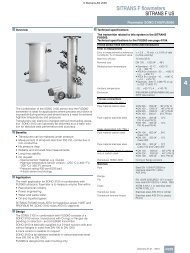
<strong>SITRANS</strong> F <strong>flowmeters</strong><strong>SITRANS</strong> F M© Siemens AG 2009Transmitter TRANSMAG 2 with sensor 911/E■ OverviewThe measuring procedure with pulsed alternating field patentedby Siemens AG is particularly suitable for media with a high solidscontent, or magnetically conducting media.■ DesignThe complete flowmeter consists of a flow sensor and an associatedtransmitter from the <strong>SITRANS</strong> F M TRANSMAG 2 forpulsed alternating field. These are available as remote version.They operate according to Faradays law of induction where anelectric voltage is induced in a conductor moving through amagnetic field.4<strong>SITRANS</strong> F M 911/TRANSMAG 2<strong>SITRANS</strong> F M TRANSMAG 2 is a pulsed alternating field magneticflowmeter where the magnetic field strength is much higherthan conventional DC pulsed magnetic <strong>flowmeters</strong>.This makes it ideal for difficult applications like:• High concentrated paper stock > 3%• Heavy mining slurries• Mining slurries with magnetic particles.TRANSMAG 2 is used with the <strong>SITRANS</strong> F M 911/E sensor,available with diameters of DN 15 to DN 1000.■ FunctionFunctionThe TRANSMAG 2 is a microprocessor-based transmitter with abuild-in alphanumeric display in several languages. The transmittersevaluate the signals from the associated electromagneticsensors and also fulfil the task of a power supply unit which providesthe magnet coils with a constant current.The magnetic flux density in the sensor is additionally monitoredby reference coils.Further information on connection, mode of operation and installationcan be found in the data sheets for the sensors.Displays and keypadOperation of the TRANSMAG 2 transmitter can be carried out using:• Keypad and display unit• HART communicator• PC/laptop and SIMATIC PDM software via HART communication• PC/laptop and SIMATIC PDM software using PROFIBUS PAcommunication■ Benefits• Fast signal processing with 16-bit technology• Automatic recognition of sensor type and calibration data asresult of SmartPLUG• PROFIBUS PA (profile 2.0) / HART communication• Simple menu operation with two-line display• Self-monitoring functions• Internal simulator (for all input and output functions)• Monitoring of sensor using magnetizing current and referencevoltage as well as wet electrode function• Analog output and digital outputs for pulses, device status,limits, flow direction, frequency output• Optional passive switch input for resetting the counter valuesor for switching off the measuring equipment (PZR)• With pulsed alternating field for minimum conductivity of≥ 1 µS/cm, on request 0.1 µS/cm depending on medium• Fully-welded steel enclosure• Liners available in hard rubber, PTFE, Linatex, Neoprene orNovolak■ ApplicationThe main applications of the <strong>SITRANS</strong> F M transmitterTRANSMAG 2 can be found in the following sectors:• Pulp & Paper Industry• Mining IndustryOperating anddisplay panelHART communicationMasterPROFIBUS PA communicationPC/laptopHARTCouplingCommunicator module <strong>RS</strong> 232PROFIBUS DP+Coupler withpower supplyPROFIBUS PA.......Min. 230 ΩTransmitter withPROFIBUS PA interfaceTBusterm.4/92 Siemens FI 01 · 2010
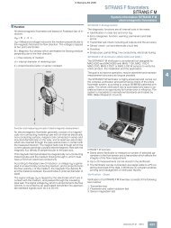
© Siemens AG 2009<strong>SITRANS</strong> F <strong>flowmeters</strong><strong>SITRANS</strong> F MTransmitter TRANSMAG 2 with sensor 911/E■ Technical specificationsTransmitter TRANSMAG 2Mode of operation and designMeasuring principleElectromagnetic with pulsed alternatingfield (PAC)Magnetic field excitationAutomatic power supply synchronization- 50 Hz AC power supply Bipolar (16.7 Hz)Bipolar with prepulse (10 Hz)Unipolar (8.33 Hz)- 60 Hz AC power supply Bipolar (20 Hz)Bipolar with prepulse (12 Hz)Unipolar (10 Hz)Accuracy under reference conditionsMeasuring tolerance of pulse output• With v > 0.25 m/s (0.82 ft/s) ≤ ±0.5% of measured value±0.0012 m/s (0.0039 ft/s)• With v < 0.25 m/s (0.82 ft/s) ±0.0025 m/s (0.0082 ft/s)Measuring tolerance of analog outputRepeatabilityReference conditions• Process temperature• Ambient temperature• Warm-up time• Installation conditions•MediumOutputsElectrical isolationCurrent outputAs pulse output plus ±0.1% conversionerror ±20 µA0.2% of measured value25 °C ±5 °C (77°F ± 9 °F)25 °C ±5 °C (77°F ± 9 °F)Min. 30 minInlet pipe section ≥ 10 x DNOutlet pipe section ≥ 5 x DNInstalled centered in pipeWater without gaseous or solidcomponentsOutputs electrically isolated fromone another and from the powersupply, max. 60 V permissibleagainst PE/equipotential bonding0/4 ... 20 mAOnly for 20 mA / HART devices(7ME5034-0…. or7ME5034-2….)• Signal- Upper limit 0/4 … 20 mA, selectable- Failure 20 … 22.5 mA,optional 3.6; 20 or 24 mA• Load-Outputmax. 600 Ω, max. load voltage15 V DC- For HART communication ≥ 250 ΩCommunicationVia analog output with PC couplingmodule or HART communicator• Protocol HART, version 5.1Digital outputSignal•OutputConfigurable as active or passivesignals- Active signal 24 V DC, ≤ 24 mA, R i = 170 Ω- Passive signal Open collector, max. 30 V DC,200 mAOutput configuration•Pulse- Pulse significance ≤ 5000 pulses/s- Pulse width ≥ 0.1 ms• Limit frequency≤ 10000 Hz•LimitsLimits for flow and quantity, flowdirection, alarmDigital output 2 (relay)(only 7ME5034-0.…)RelayNC or NO function•RatingMax. 5 W, max. 50 V AC/DC,max. 200 mA• Output configurationLimits for flow and quantity, flowdirection, alarmDigital input (optional to digitaloutput 2)(only 7ME5034-2.…)• Input function configurable ashigh-active or low-activeSet measured value or counter tozero• Signal voltage Max. 30 V DC, R i = 3 k:High level: +11 ... +30 V DCLow level: -30 ... +5 V DCFor PROFIBUS devicesPROFIBUS PA (forPROFIBUS-devices 7ME5034-1….)• CommunicationLayer 1 and 2 according toPROFIBUS PATransmission according toIEC 1158-2Layer 7 (protocol layer) accordingto PROFIBUS PA and DP V1(EN 50170)Device class B, device profile 2.0Max. 4 simultaneous C2 connections• Bus voltage9 ... 32 V DC permissible• Current consumption from bus 10 mA; limited to ≤ 15 mA in eventof fault by electrical current limitationRated operating conditionsInstallation conditionsSee also sensorsAmbient temperature•Operation-20 ... +60 °C (-4 ... +140 °F)• Display module0 ... 50 °C (32 ... 122 °F)Storage-25 ... +80 °C (-13 ... +176 °F)Degree of protectionIP67/NEMA 4XElectromagnetic compatibility(EMC)• Emitted interferenceTo EN 61326 for use in industrialareas• Noise immunityTo EN 61326 for use in industrialareasNAMUR NE21 for use in residentialareas4Siemens FI 01 · 20104/93
<strong>SITRANS</strong> F <strong>flowmeters</strong><strong>SITRANS</strong> F M© Siemens AG 20094Transmitter TRANSMAG 2 with sensor 911/EMedium conditions• Process temperature with compactdesignMinimum conductivity of medium• With <strong>SITRANS</strong> F M 911/E sensorsDesignWeight of transmitterRemote versionMaximum cable lengthHousingDisplays and keypadGeneral displayMulti-display forKeypadPower supplycorresponding to rating plate-20 ... +150 °C (-4 ... 302 °F)depending on sensor and ambienttemperature≥ 1 µS/cm,on request 0.1 µS/cm dependingon medium4.4 kg (9.7 lb)Transmitter must be connected tosensor using shielded cable100 m (328 ft)Die-cast aluminium, paintedLCD, backlid, two lines with16 characters eachFlow, totalizer, flow velocity4 keys for entering parameters• AC supply 100 ... 250 V AC ± 15%,47 ... 63 Hz• Power consumptionApprox. 120 ... 630 VA, dependingon sensorPower failureBridging of min. 1 power supplycycle (> 20 ms)Line fuse100 ... 230 V AC: T1.6AMagnet current fuseF5A / 250 V911/E sensorProcess connectionNominal diameters DN 15 ... 1000 (½" ... 40")Metering tube connectionsEN 1092-1, ANSI B16.5, others onrequestRated operating conditionsInstallation conditions• Minimum process temperature• With hard rubber liner• With PTFE liner• Linatex ® (rubber)• With Novolak linerDegree of protectionMedium conditionsMinimum conductivityMaximum flow velocityFull scale value of flow velocitySee system information-20 °C (-4 °F)Max. 90 °C (194 °F)Option: 100 °C (212 °F)• 150 °C (300 °F) at 25 bar(363 psi)• 100 °C (194 °F) at 40 bar(580 psi)-40 ... +70 °C (-40 ... +158 °F) (fortemperatures below -20 °C (-4 °F)AISI 316 flanges must be used)130 °C (266 °F) at 40 bar (580 psi)IP67/NEMA 4XOptional IP68/NEMA 6> 1 µS/cm, on request 0.1 µS/cmdepending on medium12 m/s (39.4 ft/s)0.15 ... 12 m/s (0.49 ... 39.4 ft/s)Notes on pressure equipment directiveThe devices are designed for liquids of danger group "Gases offluid group 1". The categories differ according to the version,and are listed in the table below.The minimum temperature is defined at -10 °C (14 °F) for theflange materials C22.8 (1.0460) and ST52-5 (1.0570).The minimum temperature is defined at -20 °C (-4 °F) for theflange material 1.4571/316Ti.Classification according to pressure equipment directive (PED 97/23/EC)Nominal diameter Nominal pressure Permissible media CategoryDN (inches) PN (MWP psi)15 ... 25 (½" ... 1") 10 ... 40 (145 ... 580) Gases fluid group 1 and liquids fluid group 1 Article 3.332 ... 100 (1¼" ... 4") 10 (145) Gases fluid group 1 and liquids fluid group 1 I32 ... 50 (1¼" ... 2") 16 (232) Gases fluid group 1 and liquids fluid group 1 I32 ... 40 (1¼" ... 1½") 25 (363) Gases fluid group 1 and liquids fluid group 1 I100 ... 350 (4" ... 12") 10 (145) Gases fluid group 1 and liquids fluid group 1 II65 ... 200 (2½" ... 8") 16 (232) Gases fluid group 1 and liquids fluid group 1 II50 ... 125 (2" ... 5") 25 (363) Gases fluid group 1 and liquids fluid group 1 II32 ... 80 (1¼" ... 3") 40 (580) Gases fluid group 1 and liquids fluid group 1 II350 ... 600 (14" ... 24") 10 (145) Gases fluid group 1 and liquids fluid group 1 III250 ... 600 (10" ... 24") 16 (232) Gases fluid group 1 and liquids fluid group 1 III150 ... 600 (6" ... 24") 25 (363) Gases fluid group 1 and liquids fluid group 1 III100 ... 600 (4" ... 24") 40 (580) Gases fluid group 1 and liquids fluid group 1 III4/94 Siemens FI 01 · 2010
© Siemens AG 2009<strong>SITRANS</strong> F <strong>flowmeters</strong><strong>SITRANS</strong> F MTransmitter TRANSMAG 2 with sensor 911/EProtection rings for linersFunctionContact withmediumMaterialTo protect the edges of liners fromabrasion (e.g. gravel, sand etc.).Used mainly with soft rubber linersand for PTFE liners at high temperaturesfrom 100 to 150 °C (212 to300 °F).Yes, please always check resistanceto measured medium.Stainless steel mat. No. 1.4571/316Ti,optionally Hastelloy C4 mat. No.2.4610Material thickness The overall length of the sensor isincreased by•6 mm for DN 15 to DN 150(0.24“ for ½“ to 6“) or•10 mm for DN 200 to DN 600(0.4“ for 8“ to 24“)Standard No, optional for PTFE and soft rubberliners. They are required for PTFE linersof PN 16 (MWP 232 psi) or moreinstead of protection washers, andmust be ordered separately.Order No. 7ME591x-....4Earthing washersFunctionContact withmediumMaterialElectrical reference and earthing ofthe medium. Required if the pipelinesare not electrically conducting or arelined (plastic pipelines, concretepipelines etc.). All earthing rings mustbe connected to the earthing screwpresent on the sensor.Yes, please always check resistanceto measured medium.Stainless steel mat. No. 1.4571/316Ti,or Hastelloy C4 mat. No. 2.4610Material thickness The overall length of the sensor isincreased by 2 mm (0.08“) per earthingring.Standard No, only optional. Required betweenthe medium and sensor for equipotentialbonding between non-conductingpipelines or lined pipelines.Order No. 7ME590x-....Sensor cables between sensor and transmitterThe signal voltage proportional to the flow and present at theelectrodes of the EMF is only a few µV to mV. Superimposed onthis are electrochemical interferences resulting from the contactbetween the electrodes and liquid, and which can be up to severalVolt. Also frequently superimposed are line frequency interferences,interferences resulting from vibrations on the pipelinesor signal cables, as well as strong magnetic fields in the vicinity.Sufficient shielding must therefore be provided, as well as fixedrouting of the signal cables (electrode and magnet current cable)in the case of remote versions. This also applies to deviceswith integral preamplifier (smartPLUG). The cable length betweenthe sensor and transmitter must not exceed 100 m(328 ft).Attention must also be paid to the cable routing. Signal cablesmust be routed free of vibration, and protected against strongmagnetic and stray fields. In case of doubt, the sensor cablesmust be routed in earthed steel conduit.Siemens FI 01 · 20104/95
<strong>SITRANS</strong> F <strong>flowmeters</strong><strong>SITRANS</strong> F M© Siemens AG 2009Transmitter TRANSMAG 2 with sensor 911/ESelection and Ordering data<strong>SITRANS</strong> F M electromagnetictransmitter TRANSMAG 2for alternating field, remote version,110 ... 230 V ACOrder No.7 M E 5 0 3 4 - 7 A A 7 1 - 7 A A 0AccessoriesType/descriptionOperating/Display moduleOrder No.7ME5933-0AC00Output/communication4 ... 20 mA with HART protocol 0PROFIBUS PA connection 14 ... 20 mA with HART protocol,2digital inputOperator display and keypadWithout 0With 1Electronics cover with glassplate (non Ex)7ME5933-0AC014Cable glandsM20/M16 x 1.5 1½“ NPT 2This device is shipped with a Quick Start guide and the <strong>SITRANS</strong> F manualCD containing the complete manual library. Printed OperatingInstructions are available for purchase via PMDCover for sensor cable andgasket7ME5933-0AC02Selection and Ordering dataAdditional informationPlease add “-Z“ to Order No. and specify Ordercode(s) and plain text.Order codeCover for mainssupply/communication7ME5933-0AC03Strengthened mounting bracket for wall and pipelineinstallationA02Measuring range, specify in plain text:Y01: 0 to ... m 3 /hPulse significance, specify in plain text:Y02: 0 to ... pulses/lSetting of digital outputs, specify in plain text:Y03: Setting of digital outputs: ...Y01Y02Y03Standard wall mountingbracket7ME5933-0AC04Measuring-point number (max. 8 characters), specify inplain text: Y15: ..........Y15Measuring-point description (max. 16 characters),specify in plain text: Y16: ..........Y16Special wall-/pipe mountingbracket kit7ME5933-0AC05Stainless steel tag plateY17Special design specify in plain text, state quotationY99Safety clamp for electroniccover with glass plate(7ME5933-0AC01)7ME5933-0AC06M20 cable gland set forpower and output connection,grey PA plastic, 2 pcs.• cables Ø 6 ... 12 mm(0.24" ... 0.47")• -40 ... 100 °C(-40 ... 212 °F)A5E022463501/2" NPT cable gland set forpower and output connection,grey PA plastic, 2 pcs.• cables Ø 6 ... 12 mm(0.24" ... 0.47")• -40 ... 100 °C(-40 ... 212 °F)A5E02246396M16 x 1.5 cable gland set forsensor connection, brasschrome, 2 pcs. and2 pcs. blind• cables Ø 5 ... 9 mm(0.20" ... 0.35")• -20 ... 105°C (-4 ... 221 °F)A5E022463694/96 Siemens FI 01 · 2010
© Siemens AG 2009<strong>SITRANS</strong> F <strong>flowmeters</strong><strong>SITRANS</strong> F MSelection and Ordering dataOrder No.Flowsensor <strong>SITRANS</strong> F M911/E remote version7 M E 5 6 1 0 -77777 - 7 A A 7Nominal diameterDN 15 (½")1 VDN 25 (1")2 DDN 40 (1½")2 RDN 50 (2")2 YDN 65 (2½")3 FDN 80 (3")3 MDN 100 (4")3 TDN 125 (5")4 BDN 150 (6")4 HDN 200 (8")4 PDN 250 (10")4 VDN 300 (12")5 DDN 350 (14")5 KDN 400 (16")5 RDN 450 (18")5 YDN 500 (20")6 FDN 600 (24")6 PDN 700 (28")6 YDN 750 (30")7 DDN 800 (32")7 HDN 900 (36")7 MDN 1000 (40")7 RFlange norm and pressure ratingEN 1092-1, PN 10 (DN 200 ... 1000 (8" ... 40"))BEN 1092-1, PN 16 (DN 65 ... 1000 (2½" ... 40"))CEN 1092-1, PN 25 (DN 200 ... 600 (8" ... 24"))EEN 1092-1, PN 40 (DN 15 ... 600 (½" ... 24"))FANSI B16.5, Class 150 (½" ... 24"), max 19.6 bar J(285 psi) at 20 °C (68 °F)ANSI B16.5, Class 300 (½" ... 24"), max 51.1 barK(741 psi) at 20 °C (68 °F)AWWA C207 Class D (28" ... 40")LJIS 10 K (½" ... 24")RFlange materialMid steel flanges 1.0460/1.0570 1Stainless steel flanges, AISI 316 Ti / 1.4571 3Liner materialNeoprene 1PTFE (without protection washers) 3Hardrubber 4Linatex 5Novolak (sealing material FFKM) 6Electrode materialAISI 316 Ti (mat. No. 1.4571/316 Ti) 1Hastelloy C4 (mat. No. 2.4610) 2Platinum head with shaft (mat. No. 1.4571/316Ti) 3Titanium 4Tantalum 5Cable glands/terminal boxMetric: Polyamide terminal box 1½" NPT: Polyamide terminal box 2This device is shipped with a Quick Start guide and the <strong>SITRANS</strong> Fmanual CD containing the complete manual library. Printed OperatingInstructions are available for purchase via PMDTransmitter TRANSMAG 2 with sensor 911/ESelection and Ordering dataAdditional informationPlease add “-Z“ to Order No. and specify Ordercode(s) and plain text.Two earthing (grounding) electrodes made of mat.No. 1.4571/316TiTwo earthing (grounding) electrodes made ofHastelloy C4/2.4610Two earthing (grounding) electrodes made of PlatinumheadTwo earthing (grounding) electrodes made of TitanumTwo earthing (grounding) electrodes made of TantalumFactory certificate to EN 10204-2.2Acceptance test B to DIN 50049, section 3.1 andEN 10204Silicone-free materialsTag name plate, stainless steel, add plain textOther postproduction requirements, add plain textOrder CodeA02A04A05A06A07C14C16Y04Y17Y99Selection and Ordering data Order No. Order code<strong>SITRANS</strong> F M TRANSMAG 2 and7 M E 5 9 3 0 -sensor 911/ECable for remote versions 5 7 A 0 0 - 0 A A 0 7 7 7Cable kit for sensor 911/E with alternatingfield, Magnet current cable 3 x 1.0 mm 2(3 x 0.0016 inch 2 ), electrode/referencecable 7 x 0.5 mm 2 (7 x 0.0008 inch 2 ) withshield PVC• Length: 5 m (16.4 ft)B• Length: 10 m (32.8 ft)C• Length: 20 m (65.6 ft)D• Length: 30 m (98.4 ft)E• Specify other length: in plain text Z J 1 Y4Siemens FI 01 · 20104/97
<strong>SITRANS</strong> F <strong>flowmeters</strong><strong>SITRANS</strong> F M© Siemens AG 20094Transmitter TRANSMAG 2 with sensor 911/ESelection and Ordering data Order No. Order code<strong>SITRANS</strong> F Melectromagnetic flowmeterProtection rings for flow sensor 911E 7 M E 5 9 1 2 - 7777 7 7 7(per pair)LinerHard rubber/soft rubber 1Novolak 7PTFE 0Nominal diameterfor PTFE, material 1.4571/316 TiDN 15 (½")A ADN 20 (¾")B ADN 25 (1")C ADN 32 (1¼")D ADN 40 (1½")E ADN 50 (2")F ADN 65 (2½")G ADN 80 (3")H ADN 100 (4")J ADN 125 (5")K ADN 150 (6")L ADN 200 (8")M ADN 250 (10")N ADN 300 (12")P AOther nominal diameters:Z A J 1 Yspecify in plain textfor Hard/Soft rubber, Novolak material1.471/316 TiDN 15 (½")A BDN 20 (¾")B BDN 25 (1")C BDN 32 (1¼")D BDN 40 (1½")E BDN 50 (2")F BDN 65 (2½")G BDN 80 (3")H BDN 100 (4")J BDN 125 (5")K BDN 150 (6")L BDN 200 (8")M BDN 250 (10")N BDN 300 (12")P BOther nominal diameters:Z B J 1 Yspecify in plain textFlange designFlange to DIN 1Flange to ANSI 2Flange to JIS 3Selection and Ordering dataAdditional informationPlease add “-Z“ to Order No. and specify Ordercode(s) and plain text.Tag plate of stainless steel• Y30 - tag number (max. 16 digits, specifiy in plain text• Special design, specify quotation No./date in plain textOrder codeY17Y99Selection and Ordering data Order No. Order code<strong>SITRANS</strong> F Melectromagnetic flowmeterEarthing rings for flow sensor 911E 7 M E 5 9 0 2 - 7777 7 7 7(per unit)LinerHard rubber/soft rubber 1Novolak 7PTFE 0Nominal diameterMaterial 1.4571/316 TiDN 15 (½")A ADN 20 (¾")B ADN 25 (1")C ADN 32 (1¼")D ADN 40 (1½")E ADN 50 (2")F ADN 65 (2½")G ADN 80 (3")H ADN 100 (4")J ADN 125 (5")K ADN 150 (6")L ADN 200 (8")M ADN 250 (10")N ADN 300 (12")P ADN 350 (14")Q ADN 400 (16")R ADN 500 (20")S ADN 600 (24")T ADN 700 (28")U ADN 800 (32")V ADN 900 (36")WADN 1000 (40")X AOther nominal diam.: specify in plain text Z A J 1 YMaterial Hastelloy C4/2.4610DN 15 (½")A BDN 20 (¾")B BDN 25 (1")C BDN 32 (1¼")D BDN 40 (1½")E BDN 50 (2")F BDN 65 (2½")G BDN 80 (3")H BDN 100 (4")J BDN 125 (5")K BDN 150 (6")L BDN 200 (8")M BDN 250 (10")N BDN 300 (12")P BDN 350 (14")Q BDN 400 (16")R BDN 500 (20")S BDN 600 (24")T BOther nominal diam.: specify in plain text Z B J 1 YFlange designFlange to DIN 1Flange to ANSI 2Flange to JIS 3Selection and Ordering dataAdditional informationPlease add “-Z“ to Order No. and specify Ordercode(s) and plain text.Special design, specify quotation No./date in plain textOrder codeY994/98 Siemens FI 01 · 2010
© Siemens AG 2009<strong>SITRANS</strong> F <strong>flowmeters</strong><strong>SITRANS</strong> F MTransmitter TRANSMAG 2 with sensor 911/E■ Dimensional drawings■ Schematics90(3.54)70(2.76)TransmitterPower supply90(3.54)<strong>SITRANS</strong> F M transmitter TRANSMAG 2 with wall mounting bracket,dimensions in mm (inch)95 (3.74) 150 (5.91)205 (8.07) 92 (3.62) 153 (6.02)12785678Power supply L/NPE conductorDigital output 1active 24 V DC max. 24 mA Ri 170 Ω(active/passive)Passive open collector max. 30 V DC 200 mASensor connection0/4 ... 20mALoad 600 Ωmax. 15 V100 ... 230 V AC ±15%47-63 HzDigital output 2 (Relay)NC/NO max. 5W UC 50 V 200 mA orDigital inputHigh +11 to 30 VLow -30 to +5 V7856SensorPROFIBUSDigital output 1Passive opencollectormax. 30 DC100 mA4248 (9.76)105 (4.13)89 (3.50)154 (6.06) Ø80 (3.15)150 (5.91)567292230Coil cableMagnetic fieldcorrent 1Magnetic fieldcorrent 2PESmart plug connectSupply (-6V)Ground (0V)Supply (+6V)567292230BrownWhiteGreen/YellowGreenRedBlue<strong>SITRANS</strong> F M transmitter TRANSMAG 2 with wall and pipelinemounting bracket, dimensions in mm (inch)23245566Electrode connectElectr. 1 (EL 1)Electr. 2 (EL 2)Reference coilRef. 1Ref. 223245566BrownWhiteBlackYellow<strong>SITRANS</strong> F M transmitter TRANSMAG 2, connection diagramSiemens FI 01 · 20104/99
<strong>SITRANS</strong> F <strong>flowmeters</strong><strong>SITRANS</strong> F M© Siemens AG 2009Transmitter TRANSMAG 2 with sensor 911/E131 (5.16)155 (6.1)AD14BDL<strong>SITRANS</strong> F M flow sensor 911/E, remote version, dimensions in mm (inches)Build-in length 911/E [in mm and inches]NominaldiameterDN15Hard rubberversionSoft rubber / 270neopren version(10.63)PTFE-liner withoutprotectionwashersPTFE-liner withprotectionwashersNovolak-versionDN20DN25DN32DN40DN501) Tolerance for build-in lenght: B + 0.0 mm (0.00 inches) /- 4.0 mm (-0.157 inches).With protection rings or washers for > DN25 + 6.0 mm, > DN200 + 10.0 mm (> 1” + 0.236 inches. > 8” + 0.394 inches)DN65DN80DN100½“ ¾“ 1“ 1 ¼“ 1 ½“ 2“ 2 ½“ 3“ 4“ 5“ 6“ 8“ 10“ 12“ 14“ 16“ 20“ 24“Build-in llength B 1)270(10.83)280(11.02)280(11.02)330(12.99) 340(13.39)330(12.99) 340(13.39)DN125370(14.57)370(14.57)- 275(10.83) 325(12.79) 335(13.19) 333(13.11) 362(14.25)Dimensions of sensor housingHousing width C 170(6.69)Height H withcompact version281(11.06)Height H2 withremote version 175(6.89)Housingdiameter DWeight of PN10Version in kg(MWP 145 psiversion in lb)135(5.32)8.0(17.6)169(6.65)8.5 11.0(18.7) (24.3)11.5(25.4)DN150DN200DN250DN300DN350DN400DN500DN600410(16.14) 470(18.50) 500(19.68) 550(21.65) 600(23.62) 650(25.59) 780(30.71)410(16.14) 470(18.50) 500(19.68) 550(21.65) 600(23.62) 650(25.59) 780(30.71)401(15.79) 460(18.11) 489(19.25) 538(21.18) 588(23.15) 638(25.12) 772(30.39)240306 360 412 552(9.45)(12.05) (14.17) (16.22) (21.73)285 291 298 314 326 345 371 408 441 553 578 633 688(11.22) (11.46) (11.73) (12.36) (12.83) (13.58) (14.61) (16.06) (17.36) (21.77) (22.76) (24.92) (27.09)180(7.08)184(7.24)25.0(55.1)187.5(7.38)249(9.80)26(57.3)195(7.68)215(8.46)230(9.06)252.5(9.94)285 330(11.22) (12.99)370 347 372 424 477(14.57) (13.66) (14.65) (16.69) (18.78)274 298 324 394 442 492 469 536 631 746(10.79) (11.73) (12.76) (15.51) (17.40) (19.37) (18.46) (21.10) (24.84) (29.37)28(61.7)34(75.0)38(83.8)68 80(149.9) (176.4)90 110 150(198.4) (242.5) (330.7)210(463)370(860)4/100 Siemens FI 01 · 2010