Operating Instructions - RS Hydro
Operating Instructions - RS Hydro
Operating Instructions - RS Hydro

You also want an ePaper? Increase the reach of your titles
YUMPU automatically turns print PDFs into web optimized ePapers that Google loves.
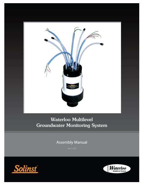
Waterloo Multilevel System Assembly Manual2.0 Installation ComponentsIndividual components of the Waterloo Multilevel System include: PVC Casing,stainless steel Base Plug or PVC Base Plug, stainless steel Ports (single and dualstem), Permanent Packers, and Wellhead Manifolds. Components are shownin Figure 2-1.Figure 2-1 Installation ComponentsPage 3
Waterloo Multilevel System Assembly ManualNote:In designingthe layout, it ispreferable toallow one totwo feet of clearance abovethe bottom of the borehole.Problems of measurementinaccuracy, sloughing duringinstallation, and otherunforeseen events whichmay prevent well completionare thus minimized.Note:If the depthto water isgreater than100 ft. (30 m)below ground surface, lowerthe system with the supportcable and drilling rig.Note:Be sure todocument theposition andplacement ofeach downhole component,during the installation. An‘as built’ installation log isa crucial part of knowingwhere each monitoring zoneis placed.3.0 PreparationThe number and specific order in which each component of the System are tobe assembled must be determined ahead of time. The depths of the desiredmonitoring zones and layers of backfill (where applicable) must be determined inadvance of the installation. The design log will serve as a reference during theinstall. Ensure that an ‘as built’ installation log is maintained. See Appendix I foran example of a “Waterloo System Installation Log”.Before the install date, reconfirm that the borehole is still open to its targetdepth. Once the Waterloo System is received, make sure that the shipmentlooks complete and that nothing appears damaged. Contact Solinst immediatelyto resolve any issues before proceeding with the install.If a Solinst Trainer is requested, the training will be completed in its entirety,prior to starting the installation. See Appendix IV for the Terms and Conditionsof training.The System weighs about 1 lbs/ft., which doesn’t include the weight of thePackers. Therefore, at least two physically strong field assistants will be neededto lower the System by hand. If the depth to water is more than 100 ft. (30 m)below ground surface, then a hoisting winch (drilling rig) will be needed to assistwith holding and lowering the System via an optional support cable.Tools and equipment you should bring for the installation:• Appropriate safety precautions and equipment to ensure a safeworking environment at your site• Water Level Meter/Well Depth Indicator• Lights and/or security if the installation goes beyond daylight hours ormore than 1 day is needed to complete the installation• Plastic sheeting to keep the Waterloo casing, tubing, etc. clean whenbeing laid out on the ground during installation• Pylons or traffic cones for safety and to identify the lay down area orwork zone• Hand-spray water bottle used to lubricate pipe joints• Two 5 gal pails• One roll of black electrical tape to temporarily identify the ports andassociated pump tube discharge ends• 11/16" (18 mm) and 5/8" (16 mm) wrenches• Hacksaw - to achieve desired System stick-up• Large dowel or spindle• Small piece of sand paper to assist in pushing tubing over the pumpstemsPage 4
Waterloo Multilevel System Assembly ManualNote:A Systemabout 100 ft.(30 m) belowwater willmost likely require wateradded to the casing stringduring installation in orderto counter System buoyancy(see Section 8.0).When packers are used, thewater inside the casing stringshould not exceed the staticwater level of the boreholeduring installation.4.0 Assembling the SystemOne person should be assigned as ‘Team Leader’ for the installation. This TeamLeader is key in directing and ensuring that the components of the System areinstalled in the correct sequence. The Team Leader will keep an ‘as built’ recordof the Multilevel System.Arrange and group all of the equipment for each separate System near theborehole. Inventory and record each piece, as is proposed for the System on theWaterloo System Installation Field Log (see Appendix I for example).Unpack the (optional) vibrating wire transducers (VWT) and soak them in water.Preferably submerse them in the borehole or in a bucket of water close intemperature to borehole groundwater. These need to stabilize prior to obtainingtheir individual ‘zero value’ (head/pressure) reading (see Section 6.2).On the most suitable ground surface, measure off and mark a line out from theborehole 10% longer then the depth to the deepest Port. By example, if thedeepest Port is at 100 ft. (30 m), measure off and make a reference mark at 110ft. (~33 m). This is your initial reference for cutting tubing. If required, unroll a~3 ft. (1 m) wide length of thin mil plastic (Visqueen) polysheeting to this mark.If used, uncoil and lay out the support cable. The outstretched cable will likely beabout 5 ft. (1.5 m) beyond the length of your plastic and reference mark.Note:If not usinga supportcable, beginwith the BasePlug near the borehole, andsimply follow the design logto attach the components insequence.Note:See Section5.0 for jointconnectioninstructionsand Section 6.0 forconnecting tubing and/orcabling to each Port.Figure 4-1 Plastic & SS Support Cable Laid Out(Wood core boxes are used here to weigh down plastic)To begin, attach the stainless steel Base Plug to the end of the support cablenearest the borehole. Following the sequence as set in your Installation Log, eachcomponent is walked to the far end of the plastic and threaded over the supportcable, female joint end first, and walked back to the borehole for connection tothe previous component. Section 5.0 discusses how to connect each joint.Page 5
Waterloo Multilevel System Assembly ManualLockAdjustmentKnobFigure 4-2 An Installation Clamp Over a BoreholeFigure 4-3 A Base Plug, Casing, Port, and Packer SectionFigure 4-4 Initial Section Being Installed Down-holePage 6
Waterloo Multilevel System Assembly ManualWhen adding each Port to the sequence you will connect the monitoring tubingand/or transducer or pump to be used at that Port. Each successive componentwill be threaded over the support cable, as well as the monitoring tubing andcabling as it is added. Section 6.0 discusses Port connections.Figure 4-5 Casing Section Being Threaded Over Monitoring TubingNote:To use theinstallationclamp, slidethe unlockingbar to the unlocked positionand open the clamp bylifting the handle. Adjustthe width of the jaws viathe adjustment knob so thecasing is held tightly whenthe clamp is closed. Returnthe locking bar to the lockedposition.Once at least 5 ft. (1.5 m) of the System has been assembled, start loweringthe System into the borehole. Adjust and lock the installation clamp onto thisassembly to hold it in place. The System is now hanging in the borehole andsupported by the installation clamp.Continue to install the System in the sequence shown in your Log, makingeach connection as described in the following section. Be sure to record thecomponents as they are assembled over the borehole on the Installation Log(see Appendix I).Page 7
Waterloo Multilevel System Assembly Manual5.0 Joint ConnectionsConnecting Casing, Packers, & PortsFigure 5-1 Packer and Casing Joint with Shear TieTools and accessories required: needle nose pliers, Oetiker pliers, hand spraywater bottle, shear ties.Note:Beforethreadingcomponentsections overthe cables/tubing, feel insidethe female joint end toensure an o-ring is present.Note:DO NOTplace theinstallationclamp on thePackers. Simply connect thenext length of casing abovethe Packer. This next casingwill be the hold point for theassembly.Figure 5-2 Tools and Accessories RequiredAll joints are pushed / twisted together over the borehole while components areheld in-place by the installation clamp or support cable. The male joint end ofthe component faces up and the female joint end faces downhole.Spray the inside of the female and male ends of the components to be attached.The water spray serves to lightly lubricate the joint to make for an easierconnection, as well as to reduce the risk of tearing the o-ring. When you aremaking this connection, be sure not to kink or pinch the monitoring tubes insidethe Multilevel System.Once the joint is coupled, push the shear tie through the shear window andaround until it exits out the same window. To help with this, needle nose plierscan be used to grab the tail of the shear tie. Lock and pull the shear tie tight.Use the Oetiker pliers to snip off the excess ‘tail’.Page 8
Waterloo Multilevel System Assembly ManualFigure 5-3 Coupled JointFigure 5-4 Push Shear Tie Through the WindowFigure 5-5 Pull Shear Tie TightFigure 5-6 Cut Off the Excess Shear TiePage 9
Waterloo Multilevel System Assembly Manual6.0 Port Connections6.1 Attaching Open TubesTools and accessories required: Oetiker pliers, tubing cutter, black electricaltape, rod/broom handle, sand paper.Figure 6-1 Tools and Accessories RequiredBeginning with the deepest Port (Port 1), stand at the borehole holding the spool oftubing. A broom handle or equivalent pole works well to hold the spool. A secondperson will ‘walk’ the end of the tubing to the measured reference mark (Section4.0). Once the tubing end is pulled to this reference mark, label the tube about1 ft. (30 cm) from the tubing end. Black electrical tape works well. Use the blacktape to wrap the number of bands corresponding to the Port number around thetubing end (i.e. 1 band of black tape represents Port 1). Cut the tubing at thespool.Figure 6-2 Tubing Being Pulled to Reference MarkNote:Rememberto label eachtubing/cableend.At the next Port, roll off the tubing to the end of the previous cut tubing length,and cut at this new reference mark. Use this reference for the remaining Ports,so as more Ports are added the tubing and cable ends will meet at the samepoint. Remember to label each length of tubing as you progress.Page 10
Waterloo Multilevel System Assembly ManualBe sure there is a clean cut to the tubing end at the Port. Place one single earOetiker clamp over the tubing and push the tubing end onto the stainless steelPort Stem. Using the Oetiker pliers, squeeze the clamp ‘shoulders’ together tosecurely attach the tubing to the stem.Figure 6-3 Tubing attached to Port Stem Using Oetiker Clamp6.2 Attaching Vibrating Wire Transducers (VWT)Tools and accessories required: 11/16" (18 mm) and 5/8" (16 mm)wrenches.Figure 6-4 Tools and Accessories RequiredPage 11
Waterloo Multilevel System Assembly ManualNote:Match the serialnumber on thebody of theVWT with thelabel at the end of the cable.Each one of the VWT’s cables has been cut to the length requested in the originalorder. This length also includes an additional 10% contingency. The total cablelength is labeled on the cable’s end.Match the serial number on the VWT body with the labeled cable end, and itscorresponding “Vibrating Wire Transducer Calibration Report” provided in theshipment (see Appendix II).Figure 6-5 Presoaking the Vibrating Wire TransducersNote:Record the VWT‘zero value’ onthe InstallationLog. It isneeded to benchmark againstall future readings.Soak all of the VWTs for about 30 minutes, in either the borehole, or in a bucketof water at the same temperature as the borehole water. Once the VWT hasstabilized, lift the VWT just out of the water and record the measured transducertemperature and vibration reading. Record this value on the Installation Log asthe VWT’s ‘zero value’.Compare this ‘zero value’ to the ‘Factory Zero Reading’ on the CalibrationReport. These values should not differ by more than 0.1% of full scale. Rememberthat pressure varies with elevation (your site vs. factory calibration location),temperature, and barometric pressure.The ‘zero value’ is used to subtract from all future pressure/head readings tocalculate final depth to water measurements. See Appendix III for a sampledepth to water calculation.Uncoil the VWT’s cable out to its full length. Push the 3/8" SS compressionfitting with attached VWT onto the Port Stem. Using the 11/16" and 5/8"wrenches, tighten the two compression fitting nuts onto the Port Stem by 1 and1/4 turns.Figure 6-6 Vibrating Wire TransducerPage 12
Waterloo Multilevel System Assembly ManualFigure 6-7Figure 6-8Page 13
Waterloo Multilevel System Assembly Manual6.3 Attaching a Pump (Bladder or Double Valve)Tools and accessories required: tubing cutter, Oetiker pliers, Oetiker clamps,sand paper, 4" (10 cm) of 1/2"OD x 3/8"ID tubing, black electrical tape,rod/broom handle.Figure 6-11 Tools and Accessories RequiredFigure 6-9 Tools and Accessories RequiredThere are two stems on each pump. The shorter stem is the sample stem, whichthe sample line (white/natural) will be connected to. The longer stem is the drivegas stem, which the drive line will be connected to. Depending on whether youuse LDPE or Teflon-lined, the drive line may be red colored or white/natural,respectively.Figure 6-10 5/8"x6" Double Valve PumpNote:Use the blacktape to wrapthe numberof bandscorresponding to the Portnumber around the tubingend (i.e. 1 band of black taperepresents Port 1).Beginning with the deepest Port (Port 1), stand at the borehole holding the spoolof tubing. A broom handle or equivalent pole works well to hold the spool.Identify/label the end of this tubing by wrapping a 1" (25 mm) piece of blackelectrical tape around the tubing to form a ‘black band’. Let each band representthe Port number. Here, one band of the tape on the tubing end will representthat this tubing will be connected to Port 1. If using Teflon tubing, use a differentcolour tape to represent the drive line tubing.A second person will ‘walk’ the end of the labelled tubing to the measuredreference mark. Once the tubing end is pulled to this reference mark. Cut thetubing at the spool.At the next Port, roll off the tubing to the end of the previous cut tubing length,and cut at this reference mark. Use this reference for the remaining Ports, soas more Ports are added, the tubing and cable ends will meet at the same point.Remember to label each length of tubing as you progress.Page 14
Waterloo Multilevel System Assembly ManualNote:If you areusing Teflonlinedtubing,be careful notto allow the Teflon lining tobecome separated and causea visible ‘bubble’ at the PortStem.Make a clean fresh cut to both tubing ends at the borehole. Place one smalldouble ear Oetiker clamp over each pump stem. Wrap a small piece of sandpaperaround the tubing for ‘traction’ and push the sample tubing over the shorterpump stem. Use the sandpaper to help push the drive tubing over the longerpump stem. If you are using Teflon-lined tubing, be sure to check that the Teflonlining has not become separated from the tubing while pushing it onto the pumpstem. If you see a ‘bubble’ through the tubing, pull it off the stem, make a freshcut, and restart this step.Figure 6-11 Using Sand Paper to Push Tubing onto Pump StemUsing the Oetiker pliers, incrementally crimp both ears on each clamp. Alternatefrom one ear to the other, slowly pinching the ears closed. Repeat this cycle 2 or3 times to achieve a proper crimp. Once the clamp is closed properly you shouldnot be able to see light through the ears of the clamp.Cut a piece of 1/2"OD x 3/8"ID tubing about 4" (100 mm) long. Push thisonto the Port Stem by about 2" (50 mm). Using the Oetiker pliers, crimp a #14Oetiker clamp over the tubing, attaching it to the Port Stem.Figure 6-12 Tubing Attached to Port StemPage 15
Waterloo Multilevel System Assembly ManualPlace another #14 Oetiker clamp over the open 1/2"OD x 3/8"ID tubing end.Push the pump intake into the tubing end. You will notice that the pump intakeis recessed to receive the Oetiker clamp. Crimp the clamp to the pump.Figure 6-13 Pump Connected to Port Stem7.0 Testing Monitoring EquipmentBefore Packer Expansion or BackfillingTools and accessories required:For testing pumps: 466 Pump Controller, 466 Drive Line Adaptor to 1/4"ODtubing (push), drive gas.For testing Vibrating Wire Transducers: VWT readout unit.For testing open tubes: Water Level Meter, Peristaltic Pump.With the Multilevel installed to depth, before adding water to activate the packersor backfilling the System, (if applicable) individually check and record VWTreadings and pumping discharges to confirm proper connections, installation,and performance.Figure 7-1 Testing Pumps and TransducersPage 16
Waterloo Multilevel System Assembly ManualNote:After theaddition ofwater, thePackers maytake 1 - 3 days to expand.This primarily dependson the Head differentialbetween the water in theborehole and the waterin the System. A higherdifferential will put morepressure on the Packers,therefore expanding themmore quickly.Note:Water is usedto counterbuoyancyand for‘sinking’ the System duringinstallation.8.0 Packer ActivationAdding WaterTools and accessories required: water.Depending on how many Packers are used, eventually your System will likelyrequire water to counter buoyancy. As a rule of thumb, when the ratio of thetotal length of casing versus the depth to water is greater than 2:1, the Systemwill float. For example, if the installed length of casing is 50 ft. (15 m) and thedepth to water is 25 ft. (7.5 m), be ready to add water. Add just enough waterto ‘sink’ the System. Do not overfill.To activate the Packers for expansion you will need about 0.2 USgals/ft.(2.5 L/m) of clean water (Therefore, a 200 ft. (60 m) Waterloo System requiresabout 40 USgals (150 L) of water). Do not overfill the System, and rememberto leave the water level in the PVC Casing below the frost line (if applicable).Repeated addition of small amounts of water may be required as the Packersinflate. The water level within the System, versus in the borehole, should notdiffer by more than 100 ft. (30 m).Figure 8-1 Adding Water to the SystemPage 17
Waterloo Multilevel System Assembly ManualNote:Allow forat least 20"(50cm) ofclearanceabove the final PVC Casing‘stick-up’ and the undersideof your protective outerenclosure. This will ensurethat you do not pinchthe monitoring tubes andcables above the completedmanifold.Note:Take a waterlevel reading inthe boreholeand record itin the “Water Level at End”box on the Installation Log,after the System is installedto depth.9.0 Wellhead Manifold Completion9.1 Standard OptionTools and accessories required: tubing cutter, Phillips screwdriver, PVC pipesaw/cutter.Determine the desired ‘stick-up’ of PVC casing when the system is at its finaldepth. If applicable, cut the last piece of PVC Riser to the appropriate lengthand install the Riser Clamp to achieve your desired ‘stick-up’. The Riser Clampensures that the proper stick-up is maintained when the System is hung. Forsafety, use a casing clamp and lower the System to depth. If you have used theSS support cable to lower the System, be sure to continue to use this cable tosupport the System during the packer expansion (up to three days).Figure 9-1 Tubing Organized Around the WellheadRemove the two Phillips screws fromthe white protective housing of theWellhead Manifold Base and thenremove the Manifold Base from the 4”(100 mm) diameter protective housing.Install this lower (black) portion ofthe Manifold (small end first) onto thecompleted installed PVC Casing. Usingthe numbered Wellhead as a guide,separate and organize the tubes and/or cables into a ‘wagon wheel’ patternaround the Wellhead.Thread the open tubes, sample tubes(white) and/or blue VWT cables throughthe numbered Wellhead. Re-attach andscrew the numbered Wellhead to theManifold Housing at the Wellhead.Figure 9-2 Tubing and Cables Installed Through a WellheadPage 18
Waterloo Multilevel System Assembly Manual9.2 Multipurge OptionIf pumps are used, follow the steps above, but before attaching the Wellhead,choose one drive line tube and hold it up against the 4” (100 mm) diameterwhite protective housing which is at its final elevation at the wellhead. Trimthe red drive line tube at a point about 2” (50 mm) above the white protectivehousing. Insert this tubing end into the white (translucent) plastic compressionfitting on the base of the numbered Wellhead. You should be able to see the redtubing pass through this fitting. Hand tighten the fitting. Repeat this procedureon the remaining drive tubes. Re-attach the numbered Wellhead to the ManifoldHousing at the Wellhead and tighten the screws.Figure 9-3 Pump Tubing Being Attached to a WellheadPage 19
Waterloo Multilevel System Assembly Manual9.3 Wellhead ProtectionAllow sufficient wellhead access when you install a protective cover over thewell. Use a large well cover to allow plenty of room to access the wellhead. Thefollowing diagrams show some suggested completions for the 401 MultilevelSystem. These enclosures are not available at Solinst, however they are availablefrom most drilling contractors.Min. 24" (60cm)20" (50 cm)Min.SteelCasingFigure 9-4Waterloo Multilevel Wellhead Inside Flushmount VaultClear Access 20” (50 cm)Figure 9-5Typical Road Box or VaultFigure 9-6Above ground completionMinimum 6” dia. (15 cm) and20”(50 cm) clearance is requiredPage 20
Waterloo Multilevel System Assembly Manual10.0 Monitoring OptionsWater levels and samples can be accurately obtained usingthe following high quality Solinst instruments:Water Level MeasurementModel 102 Water Level MeterSampling MethodsDepending on the depth to water at your site, and yoursampling protocol, Solinst offers various sampling options.Model 410 Peristaltic PumpIdeal for sample retrieval from shallow water levels less than30 ft. (9 m).The narrow coaxial cable Model 102 Water Level Meterand 102M Mini Water Level Meter with a 1/4" (6.3 m) dia.probe can be used to monitor water levels in open tubes.The coaxial cable is accurately laser marked every 1/100ft or mm.Model 408M (3/8" Dia.)Micro Double Valve PumpThe Small and flexible design makes this gas drive pumpideal for delivering high quality samples, in combinationwith the Model 466 Electronic Control Unit. Flow rates of20 to 150 mL/min make the 408M suitable for low flowsampling applications. Constructed of stainless steel andLDPE for lengths less than50 ft. (15 m) and Teflon®tubing for any depths up to250 ft. (75 m) applications.This is the only viable optionin wells with depth to waterover 150 ft. (45 m).Well CompletionModel 464Model 103 Tag LineElectronic Control UnitThe Tag Line is ideal to aid accurate placement of sandand bentonite during borehole completion.Durable & easy to operate withthe 408M by using the presetsand fine tuning capabilitiesbuilt into the Solinst Model464 Electronic Control Unit.Mini Inertial PumpThis Mechanical pump uses 1/4" LDPE tubing.Typical flow rates of 50 to 250 ml/min. Suitablefor use to depths of approximately 150 ft. (45 m).If the water level on your site is deeper than 50 ft.® Teflon is a registered trademark of DuPont Corp.(15 m), Teflon® tubing is recommended.Page 21
Waterloo Multilevel System Assembly Manual - AppendixPage I
Waterloo Multilevel System Assembly Manual - AppendixPage II
Waterloo Multilevel System Assembly Manual - AppendixSample CalculationConverting a VWT reading from the GK-404 to a depth to waterIn our example, let's assume the VWT is connected to a monitoring port that is located at a depth of 100 ft (30.48 m)below ground surface.From the GK-404 readout:Zero Reading (pre installation) of VWT: 9978 digitsSubmerged Reading of VWT: 7978 digitsDifference between Zero Reading & Submerged Reading: 2000 digitsFrom the "Vibrating Wire Pressure Transducer Calibration Report" (sample in Appendix III), locate the "Linear GageFactor" for each specific transducer serial number. In our example:To calculate the pressure head (psi or kPa) on the VWT, multiply the appropriate "Linear Gage Factor", by thedifference between the zero reading and submerged reading. From our example:0.006986 (psi/digit) x 2000 digits = 13.972 psi (96.33 kPa)Therefore, VWT serial number 06-5822 has a pressure head of 13.972 psi (96.33 kPa).To calculate the depth to water, simply convert psi (kPa) to feet (meters):13.972 psi x 2.307 foot of head/psi = 32.23 feet of head.96.33 kPa x 0.1020 meter of head/kPa = 9.826 meters of headNow subtract the depth to the Port inlet (100ft/30.48m) from the pressure head.100 ft - 32.23 feet of head = 67.77 ft.30.48 m - 9.826 meters of head = 20.65 mPage III
Waterloo Multilevel System Assembly Manual - AppendixPage IV