Catalog 51-M Catalog 51 - TeeJet
Catalog 51-M Catalog 51 - TeeJet
Catalog 51-M Catalog 51 - TeeJet
- No tags were found...

You also want an ePaper? Increase the reach of your titles
YUMPU automatically turns print PDFs into web optimized ePapers that Google loves.
<strong>Catalog</strong> <strong>51</strong>-MLeaders in precisionapplication components,control system technology,and application datamanagement.www.teejet.com
Table of ContentsSelection Guide<strong>TeeJet</strong>® Broadcast Nozzle Selection Guide ............ 2<strong>TeeJet</strong> Specialty Application NozzleSelection Guide ................................... 3<strong>TeeJet</strong> Liquid Fertilizer Nozzle Selection Guide. . . . . . . . 4Broadcast NozzlesTurbo <strong>TeeJet</strong>® Wide Angle Flat Spray Tips ............ 5AIXR <strong>TeeJet</strong> Air Induction Flat Spray Tips .............. 6AI <strong>TeeJet</strong> Air Induction Flat Spray Tips ................ 7AIC <strong>TeeJet</strong> Air Induction Flat Spray Tips ............... 8Turbo <strong>TeeJet</strong> Induction Flat Spray Tips ............... 9XR <strong>TeeJet</strong>® Extended Range Flat Spray Tips ..........10XRC <strong>TeeJet</strong> Extended Range Flat Spray Tips. . . . . . . . . . 11<strong>TeeJet</strong> VisiFlo® Flat Spray Tips .......................12DG <strong>TeeJet</strong>® Drift Guard Flat Spray Tips ...............13Turbo TwinJet® Twin Flat Spray Tips .................14Air Induction Turbo TwinJet Twin Flat Spray Tips .....15TwinJet® Twin Flat Spray Tips ........................16Turbo <strong>TeeJet</strong> Duo Dual Polymer Flat Fan Spray Tips ..17DG TwinJet® Drift Guard Twin Flat Spray Tips .........18Turbo FloodJet® Wide Angle Flat Spray Tips .........19FloodJet® Wide Angle Flat Spray Tips .............. 20Quick Turbo FloodJet Wide AngleFlat Spray Tips ....................................21TurfJet Wide Angle Flat Fan Spray Nozzles ...........22<strong>TeeJet</strong> Double Outlet Flat Spray Tips ................23<strong>TeeJet</strong> Off-Center Flat Spray Tips –Smaller Capacities ................................23FullJet® Wide Angle Full Cone Spray Tips .............24Boomless NozzlesXP BoomJet® Boomless Flat Spray Nozzles ..........25BoomJet® Boomless Nozzles with Extra WideFlat Spray Projection .............................26<strong>TeeJet</strong> Swivel Spray Nozzles with Off-CenterFlat Spray Tips—Larger Capacities .............. 26FieldJet® Boomless Nozzles with Extra WideFlat Spray Projection .............................27Banding NozzlesConeJet® VisiFlo Hollow Cone Spray Tips ............28AI <strong>TeeJet</strong> Air Induction Even Flat Spray Tips ........29DG <strong>TeeJet</strong> Drift Guard Even Flat Spray Tips .........30<strong>TeeJet</strong> Even Flat Spray Tips .........................31TwinJet Even Flat Spray Tips ........................32AIUB <strong>TeeJet</strong> Banding and DirectedSpray Nozzles ....................................33<strong>TeeJet</strong> Full Cone Spray Tips .........................34<strong>TeeJet</strong> UB—Underleaf Banding Spray Tips ............34ConeJet Ceramic VisiFlo Spray Tips ..................35Air Blast NozzlesConeJet VisiFlo Hollow Cone Spray Tips .............36ConeJet VisiFlo Hollow Cone Spray Tips .............37AITX ConeJet Air Induction Hollow Cone Spray Tip ...38ConeJet VisiFlo Hollow Cone Spray Tips .............39<strong>TeeJet</strong> VisiFlo Flat Spray Tips .........................39<strong>TeeJet</strong> Disc-Core Type Hollow Cone Spray Tips .......40<strong>TeeJet</strong> Disc-Core Type Full Cone Spray Tips ..........41Fertilizer NozzlesStreamJet SJ3 Fertilizer Nozzles ......................42StreamJet SJ7 Fertilizer Nozzles ......................43<strong>TeeJet</strong> Flow Regulators ..............................44StreamJet Solid Stream Spray Nozzles ...............45Tank Rinsing Nozzles<strong>TeeJet</strong> Tank Rinsing Nozzles .........................46<strong>TeeJet</strong> Container Rinsing Nozzles ....................46<strong>TeeJet</strong> Eductor Nozzles ..............................47<strong>TeeJet</strong> Jet Agitators. . . . . . . . . . . . . . . . . . . . . . . . . . . . . . . . . . 47Boom ComponentsQuick <strong>TeeJet</strong>® Multiple Nozzle BodyAssemblies for Dry Booms .......................48<strong>TeeJet</strong> Vari-Spacing Clamps for Useon Dry Boom Quick <strong>TeeJet</strong> Bodies ................48Quick <strong>TeeJet</strong> Multiple Nozzle Body Assembliesfor Dry Booms ....................................49Quick <strong>TeeJet</strong> Multiple Nozzle Body Assemblies ......50Quick <strong>TeeJet</strong> Multiple Nozzle Body Assemblieswith Fertilizer Outlets for Dry Booms .............50Quick <strong>TeeJet</strong> Single Nozzle Bodiesfor Dry Booms ....................................<strong>51</strong>Quick <strong>TeeJet</strong> Multiple Nozzle Bodiesfor Wet Booms ............................... 52–53Quick <strong>TeeJet</strong> Triple Nozzle Bodiesfor Wet Booms ...................................54Quick <strong>TeeJet</strong> Multiple Nozzle Body Assemblieswith Fertilizer Outlets for Wet Booms .............54Quick <strong>TeeJet</strong> Multiple Nozzle Bodiesfor Wet Booms ...................................55www.teejet.com
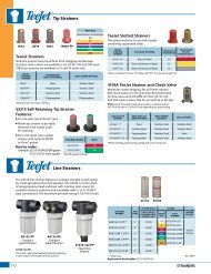
Quick <strong>TeeJet</strong> Single Nozzle Bodiesfor Wet Booms ....................................56Quick <strong>TeeJet</strong> Caps for Hardi® Nozzle Bodies...........56Quick <strong>TeeJet</strong> Caps....................................57Quick <strong>TeeJet</strong> Adapters and Accessories...............58<strong>TeeJet</strong> ChemSaver® Diaphragm Check Valves.........59<strong>TeeJet</strong> Nozzle Body ChemSaver Check Valves.........60<strong>TeeJet</strong> Speciality Fittings..............................61<strong>TeeJet</strong> Row Application Kit ...........................61<strong>TeeJet</strong> Swivel Nozzle Bodies..........................62<strong>TeeJet</strong> Hose Drops....................................62<strong>TeeJet</strong> Hose Shank Nozzle Bodies.....................63<strong>TeeJet</strong> Split Eyelet Nozzle Bodies.....................63<strong>TeeJet</strong> Nozzle Parts............................... 64–65Valves & ManifoldsDirectoValve® B Style Electric Motors and Valves......66DirectoValve B Style Motors..........................67DirectoValve Electric Regulating Valves...............68DirectoValve Flow Back Manifolds....................69DirectoValve Electric Regulating Ball Valves....... 70–71DirectoValve 344 Series ElectricShutoff Valves................................. 72–73DirectoValve 346 Series Shutoff Valves ........... 74–75DirectoValve 356 Series FlangedShutoff Valves................................. 76–77DirectoValve Normally-Open (Bypass) Valves ..... 78–79DirectoValve 430 Series 2-Way Manifold..............80DirectoValve 430 Series 3-Way Manifold..............81DirectoValve 430 Series Flow Back Manifold...... 82–83DirectoValve Control Unit for <strong>TeeJet</strong> Controllers .. 84–85Individual 430 Manifold Accessories................... 85DirectoValve 440 Series ManifoldShutoff Valves................................. 86–87DirectoValve 450 Series Shutoff Manifold......... 88–89DirectoValve 450 Series Flow Back Manifold...... 90–91DirectoValve 460 Series 2-Way Manifold.......... 92–93DirectoValve 460 Series 3-Way Manifold.......... 94–95DirectoValve 460 Series Flow Back Manifold...... 96–97DirectoValve 490 Series Shutoff Manifold......... 98–99DirectoValve 540 Series Shutoff Manifold...... 100–101DirectoValve Flange Fittings................... 102–103DirectoValve Quick Connect Fittings................ 104DirectoValve Electrical Connectors ................. 105DirectoValve 2-Way ElectricallyOperated Solenoid Valves....................... 106DirectoValve 3-Way ElectricallyOperated Solenoid Valves....................... 107DirectoValve Solenoid Foam Marker Valves......... 107DirectoValve 340 Series2-Way Manual Shutoff Ball Valves ............... 108DirectoValve 340 Series3-Way Manual Bypass Ball Valves................ 109DirectoValve Manual PressureRelief/Regulating Valves......................... 110DirectoValve Manual Control Valves................ 111TeeValve® Control Valves........................... 111<strong>TeeJet</strong> Throttling Valves............................ 111Strainers<strong>TeeJet</strong> Tip Strainers................................. 112<strong>TeeJet</strong> Line Strainers........................... 112–115Spray GunsGunJet® Spray Guns...................... 116–117, 119MeterJet® Spray Guns .............................. 118<strong>TeeJet</strong> Lawn Spray Guns............................ 118TriggerJet® Spray Guns........................ 120–121ConeJet Adjustable Spray Tips...................... 122<strong>TeeJet</strong> Shutoff Valves and Spray Guns.............. 123Technical InformationFormulas and Factors.......................... 124–125Spray Coverage Information........................ 125Nozzle Nomenclature .............................. 125Universal Application Rate Chart .............. 126–127Information About Spray Pressure.................. 128Pressure Drop Through Sprayer Componants....... 129Area Measurement................................. 130Sprayer Calibration................................. 131Calibration/Adjustment Accessories................ 132Spray Tip Wear. . . . . . . . . . . . . . . . . . . . . . . . . . . . . . . . . . . . . . 133Spray Distribution Quality.......................... 134Droplet Size and Drift Information.................. 135Drop Size Classification........................ 136–137Drift Causes and Control....................... 138–139Assesment of Nozzle Drift Control in Europe........ 140Plumbing Diagrams................................ 141Notes.......................................... 142–143Terms and Conditions.............................. 144The Easy Decision for Precision.
Broadcast Nozzle Selection GuideHerbicides fungicides insecticidessoilappliedPost-emergencecontactsystemiccontact systemic contact systemicdriftmanagementReference page 5veryGOODveryGOODveryGOODveryGOODveryGOODveryGOODveryGOODat pressures below 30 PSI (2.0 bar)Reference page 5GOOD GOOD EXCELLENT GOOD EXCELLENT GOOD EXCELLENTveryGOODReference page 14GOODEXCELLENT EXCELLENT EXCELLENT EXCELLENT EXCELLENT EXCELLENTveryGOODat pressures below 30 PSI (2.0 bar)Reference page 14veryGOODveryGOODEXCELLENTveryGOODEXCELLENTveryGOODEXCELLENT EXCELLENTReference page 9EXCELLENT EXCELLENT EXCELLENT EXCELLENT EXCELLENTReference page 15veryGOODGOOD EXCELLENT GOOD EXCELLENT GOOD EXCELLENT EXCELLENT,Reference pages 10–11EXCELLENT GOOD EXCELLENT GOOD EXCELLENT GOOD GOOD,at pressures below 30 PSI (2.0 bar)Reference pages 10–11GOODGOODveryGOODGOODveryGOODGOODveryGOODveryGOODReference page 6veryGOODGOOD EXCELLENT GOOD EXCELLENT GOOD EXCELLENT EXCELLENT,Reference pages 7–8veryGOODGOOD EXCELLENT GOOD EXCELLENT GOOD EXCELLENT EXCELLENTReference page 16EXCELLENT EXCELLENT EXCELLENTReference page 18veryGOODveryGOODEXCELLENTveryGOODEXCELLENTveryGOODEXCELLENTveryGOODReference page 19EXCELLENTveryGOODveryGOODveryGOODEXCELLENTReference page 22EXCELLENT EXCELLENT EXCELLENT EXCELLENT EXCELLENTReference page 21EXCELLENTEXCELLENTContact your regional sales officefor additional informationEXCELLENT EXCELLENT EXCELLENT EXCELLENT EXCELLENT EXCELLENT EXCELLENT EXCELLENTNote: Consult the chemical manufacturer’s product label for specific rate and application recommendations.2SELECTION GUIDE
Specialty Application Nozzle Selection GuideHerbicides fungicides insecticidesPost-emergencePreemergencecontactsystemiccontact systemic contact systemicevenReference page 29EXCELLENT GOOD EXCELLENT GOOD EXCELLENT GOOD EXCELLENTbandingevenReference page 31GOOD very GOOD GOOD very GOOD GOOD very GOOD GOODevenReference page 32EXCELLENT EXCELLENT EXCELLENTevenReference page 29very GOOD GOOD EXCELLENT GOOD EXCELLENT GOOD EXCELLENTevenReference page 31GOOD GOOD GOOD GOOD GOOD GOOD GOODdirected sprayingevenReference page 32Reference page 33very GOOD very GOOD very GOODGOOD EXCELLENT GOOD EXCELLENT GOOD EXCELLENTReference page 38GOOD EXCELLENT GOOD EXCELLENT GOOD EXCELLENTReference pages 28 & 35EXCELLENT EXCELLENT EXCELLENTair BlastReference pages 36–37Reference pages 40–41EXCELLENT GOOD EXCELLENT GOOD EXCELLENT GOODEXCELLENT GOOD EXCELLENT GOOD EXCELLENT GOODNote: Consult the chemical manufacturer’s product label for specific rate and application recommendations.SELECTION GUIDE3
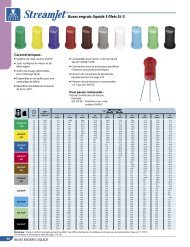
Liquid Fertilizer Nozzle Selection GuideLIQUID FERTILIZER APPLICATIONbroadcastdirectedJust as in applying crop protection products, the proper applicationof liquid fertilizer is important. Delivering nutrients to the cropin a timely and effective manner while minimizing crop damageis essential. <strong>TeeJet</strong> Technologies offers an extensive selection ofnozzles specifically designed to maximize the performance of yourliquid fertilizer application.(7-ORIFICE)Reference page 43EXCELLENTvery GOODSolid stream nozzles, offered in both single- and multiple-streamversions, are designed to deliver fertilizer to the soil surface whereit can be effectively utilized by the crop. By creating solid liquidstreams, these nozzles greatly reduce foliar coverage in standingcrop in order to minimize leaf burn. <strong>TeeJet</strong> Technologies StreamJetnozzles provide the ideal blend of compact, reliable design, ease ofinstallation and affordable pricing.(3-ORIFICE)Reference page 42very GOODEXCELLENTIn some cases, the use of a broadcast nozzle for fertilizer applicationmay be desirable. This could include combined fertilizer/pesticideapplications, foliar feeding or broadcast liquid fertilization of bareground. For these applications <strong>TeeJet</strong> Technologies offers a widevariety of low drift, flat spray nozzles.(Single-ORIFICE)Reference page 45EXCELLENTLiquid Density ConversionCP4916(ORIFICE PLATE)Reference page 44EXCELLENTWhen selecting a specific capacity tip for liquid fertilizer application,always correct for liquid density. Application charts shown in thiscatalog are based on spraying water. Many fertilizer solutions aredenser than water, which will affect the application rate. Please seepage 125 for a list of density conversion factors.(LARGE CAPACITY)Reference page 12very GOODExample:Desired application rate is 100 l/ha of a liquid that has a density of1.28 kg/l. Determine the correct nozzle size as follow:(LOW VOLUME)Reference pages 7–8very GOODl/ha (liquid other than water) x Conversion Factor = l/ha (from tablein catalog)100 l/ha (1.28 kg/l solution) x 1.13 = 113 l/ha (water)(LOW VOLUME)Reference page 33very GOODThe applicator should choose a nozzle size that will supply 113 l/haof water at the desired pressure.Reference page 9EXCELLENTReference page 19EXCELLENTReference page 21EXCELLENTNote: Consult the chemical manufacturer’s product label for specific rate and application recommendations.4SELECTION GUIDE
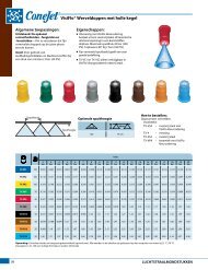
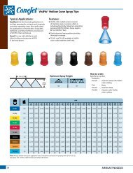
Wide Angle Flat Spray TipsTypical Applications:See selection guide on page 2 forrecommended typical applicationsfor Turbo <strong>TeeJet</strong> tips.Features:n Tapered edge wide angle flat spray patternfor uniform coverage in broadcast spraying.n Large, rounded internal passage tominimize clogging.n Excellent resistance to corrosive solutions.n Superior wear characteristics.n Larger droplets for less drift—15–90 PSI (1–6 bar).n Automatic spray alignment with 25612-*-NYRQuick <strong>TeeJet</strong>® cap and gasket. Reference page57 for more information.n Blockage-free passage means less clogging.n Unique internal configuration meanssubstantially longer wear life.TT11001(100)TT110015(100)TT11002(50)TT110025(50)TT11003(50)TT11004(50)TT11005(50)TT11006(50)TT11008(50)barDropSizecapacityonenozzlein l/min4km/h5km/h6km/h7km/h8km/h1.0 C 0.23 69.0 55.2 46.0 39.4 34.5 27.6 23.0 17.3 15.3 13.8 11.0 9.2 7.92.0 M 0.32 96.0 76.8 64.0 54.9 48.0 38.4 32.0 24.0 21.3 19.2 15.4 12.8 11.03.0 F 0.39 117 93.6 78.0 66.9 58.5 46.8 39.0 29.3 26.0 23.4 18.7 15.6 13.44.0 F 0.45 135 108 90.0 77.1 67.5 54.0 45.0 33.8 30.0 27.0 21.6 18.0 15.45.0 F 0.50 150 120 100 85.7 75.0 60.0 50.0 37.5 33.3 30.0 24.0 20.0 17.16.0 F 0.55 165 132 110 94.3 82.5 66.0 55.0 41.3 36.7 33.0 26.4 22.0 18.91.0 C 0.34 102 81.6 68.0 58.3 <strong>51</strong>.0 40.8 34.0 25.5 22.7 20.4 16.3 13.6 11.72.0 M 0.48 144 115 96.0 82.3 72.0 57.6 48.0 36.0 32.0 28.8 23.0 19.2 16.53.0 M 0.59 177 142 118 101 88.5 70.8 59.0 44.3 39.3 35.4 28.3 23.6 20.24.0 M 0.68 204 163 136 117 102 81.6 68.0 <strong>51</strong>.0 45.3 40.8 32.6 27.2 23.35.0 F 0.76 228 182 152 130 114 91.2 76.0 57.0 50.7 45.6 36.5 30.4 26.16.0 F 0.83 249 199 166 142 125 99.6 83.0 62.3 55.3 49.8 39.8 33.2 28.<strong>51</strong>.0 C 0.46 138 110 92.0 78.9 69.0 55.2 46.0 34.5 30.7 27.6 22.1 18.4 15.82.0 C 0.65 195 156 130 111 97.5 78.0 65.0 48.8 43.3 39.0 31.2 26.0 22.33.0 M 0.79 237 190 158 135 119 94.8 79.0 59.3 52.7 47.4 37.9 31.6 27.14.0 M 0.91 273 218 182 156 137 109 91.0 68.3 60.7 54.6 43.7 36.4 31.25.0 M 1.02 306 245 204 175 153 122 102 76.5 68.0 61.2 49.0 40.8 35.06.0 F 1.12 336 269 224 192 168 134 112 84.0 74.7 67.2 53.8 44.8 38.41.0 VC 0.57 171 137 114 97.7 85.5 68.4 57.0 42.8 38.0 34.2 27.4 22.8 19.52.0 C 0.81 243 194 162 139 122 97.2 81.0 60.8 54.0 48.6 38.9 32.4 27.83.0 M 0.99 297 238 198 170 149 119 99.0 74.3 66.0 59.4 47.5 39.6 33.94.0 M 1.14 342 274 228 195 171 137 114 85.5 76.0 68.4 54.7 45.6 39.15.0 M 1.28 384 307 256 219 192 154 128 96.0 85.3 76.8 61.4 <strong>51</strong>.2 43.96.0 M 1.40 420 336 280 240 210 168 140 105 93.3 84.0 67.2 56.0 48.01.0 VC 0.68 204 163 136 117 102 81.6 68.0 <strong>51</strong>.0 45.3 40.8 32.6 27.2 23.32.0 C 0.96 288 230 192 165 144 115 96.0 72.0 64.0 57.6 46.1 38.4 32.93.0 C 1.18 354 283 236 202 177 142 118 88.5 78.7 70.8 56.6 47.2 40.54.0 M 1.36 408 326 272 233 204 163 136 102 90.7 81.6 65.3 54.4 46.65.0 M 1.52 456 365 304 261 228 182 152 114 101 91.2 73.0 60.8 52.16.0 M 1.67 501 401 334 286 2<strong>51</strong> 200 167 125 111 100 80.2 66.8 57.31.0 XC 0.91 273 218 182 156 137 109 91.0 68.3 60.7 54.6 43.7 36.4 31.22.0 C 1.29 387 310 258 221 194 155 129 96.8 86.0 77.4 61.9 <strong>51</strong>.6 44.23.0 C 1.58 474 379 316 271 237 190 158 119 105 94.8 75.8 63.2 54.24.0 C 1.82 546 437 364 312 273 218 182 137 121 109 87.4 72.8 62.45.0 M 2.04 612 490 408 350 306 245 204 153 136 122 97.9 81.6 69.96.0 M 2.23 669 535 446 382 335 268 223 167 149 134 107 89.2 76.<strong>51</strong>.0 XC 1.14 342 274 228 195 171 137 114 85.5 76.0 68.4 54.7 45.6 39.12.0 VC 1.61 483 386 322 276 242 193 161 121 107 96.6 77.3 64.4 55.23.0 C 1.97 591 473 394 338 296 236 197 148 131 118 94.6 78.8 67.54.0 C 2.27 681 545 454 389 341 272 227 170 1<strong>51</strong> 136 109 90.8 77.85.0 C 2.54 762 610 508 435 381 305 254 191 169 152 122 102 87.16.0 M 2.79 837 670 558 478 419 335 279 209 186 167 134 112 95.71.0 XC 1.37 411 329 274 235 206 164 137 103 91.3 82.2 65.8 54.8 47.02.0 VC 1.94 582 466 388 333 291 233 194 146 129 116 93.1 77.6 66.53.0 C 2.37 711 569 474 406 356 284 237 178 158 142 114 94.8 81.34.0 C 2.74 822 658 548 470 411 329 274 206 183 164 132 110 93.95.0 C 3.06 918 734 612 525 459 367 306 230 204 184 147 122 1056.0 M 3.35 1005 804 670 574 503 402 335 2<strong>51</strong> 223 201 161 134 11<strong>51</strong>.0 XC 1.82 546 437 364 312 273 218 182 137 121 109 87.4 72.8 62.42.0 VC 2.58 774 619 <strong>51</strong>6 442 387 310 258 194 172 155 124 103 88.53.0 C 3.16 948 758 632 542 474 379 316 237 211 190 152 126 1084.0 C 3.65 1095 876 730 626 548 438 365 274 243 219 175 146 1255.0 C 4.08 1224 979 816 699 612 490 408 306 272 245 196 163 1406.0 M 4.47 1341 1073 894 766 671 536 447 335 298 268 215 179 153BROADCAST NOZZLESl/ha10km/h12km/h50 cm16km/h18km/h20km/hNote: Always double check your application rates. Tabulations are based on spraying water at 70°F (21°C).See pages 124–140 for drop size classification, useful formulas and other information.25km/h30km/h35km/hCONTACTProductSpacing110°SYSTEMICProductOptimum Spray HeightDRIFTManagementVery Good Very Good Very GoodGood* EXCELLENT* Very Good**At pressures below 30 PSI (2.0 bar)50 cm50 cmHow to order:Specify tip number.Example:TT11001-VP – Polymer with VisiFlo®color-codingSprayHeight5
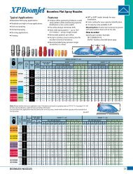
Air Induction XR Flat Spray TipsTypical Applications:See selection guide on page 2 forrecommended typical applicationsfor AIXR <strong>TeeJet</strong> tips.Features:n 110° wide, tapered flat spray angle withair induction technology offers betterdrift management.n Made of a two-piece UHMWPE polymerconstruction with VisiFlo® color-coding.UHMPE provides excellent chemicalresistance, including acids, as well asexceptional wear life.n Compact size to prevent tip damage.n Depending on the chemical, produceslarge air-filled drops through a Venturiair aspirator.n Removable pre-orifice.n Available in seven tip capacities witha wide operating pressure range:15–90 PSI (1–6 bar).n Automatic alignment when used with25612-*-NYR Quick <strong>TeeJet</strong>® cap and gasket.Reference page 57 for more information.ChamferRemovablePre-OrificeO-RingAIXR110015(100)AIXR11002(50)AIXR110025(50)AIXR11003(50)AIXR11004(50)AIXR11005(50)AIXR11006(50)barDropSizecapacityonenozzlein l/min4km/h5km/h6km/h7km/h8km/h1.0 XC 0.34 102 81.6 68.0 58.3 <strong>51</strong>.0 40.8 34.0 25.5 22.7 20.4 16.3 13.6 11.72.0 VC 0.48 144 115 96.0 82.3 72.0 57.6 48.0 36.0 32.0 28.8 23.0 19.2 16.53.0 C 0.59 177 142 118 101 88.5 70.8 59.0 44.3 39.3 35.4 28.3 23.6 20.24.0 C 0.68 204 163 136 117 102 81.6 68.0 <strong>51</strong>.0 45.3 40.8 32.6 27.2 23.35.0 M 0.76 228 182 152 130 114 91.2 76.0 57.0 50.7 45.6 36.5 30.4 26.16.0 M 0.83 249 199 166 142 125 99.6 83.0 62.3 55.3 49.8 39.8 33.2 28.<strong>51</strong>.0 XC 0.46 138 110 92.0 78.9 69.0 55.2 46.0 34.5 30.7 27.6 22.1 18.4 15.82.0 VC 0.65 195 156 130 111 97.5 78.0 65.0 48.8 43.3 39.0 31.2 26.0 22.33.0 C 0.79 237 190 158 135 119 94.8 79.0 59.3 52.7 47.4 37.9 31.6 27.14.0 C 0.91 273 218 182 156 137 109 91.0 68.3 60.7 54.6 43.7 36.4 31.25.0 C 1.02 306 245 204 175 153 122 102 76.5 68.0 61.2 49.0 40.8 35.06.0 M 1.12 336 269 224 192 168 134 112 84.0 74.7 67.2 53.8 44.8 38.41.0 XC 0.57 171 137 114 97.7 85.5 68.4 57.0 42.8 38.0 34.2 27.4 22.8 19.52.0 XC 0.81 243 194 162 139 122 97.2 81.0 60.8 54.0 48.6 38.9 32.4 27.83.0 VC 0.99 297 238 198 170 149 119 99.0 74.3 66.0 59.4 47.5 39.6 33.94.0 C 1.14 342 274 228 195 171 137 114 85.5 76.0 68.4 54.7 45.6 39.15.0 C 1.28 384 307 256 219 192 154 128 96.0 85.3 76.8 61.4 <strong>51</strong>.2 43.96.0 C 1.40 420 336 280 240 210 168 140 105 93.3 84.0 67.2 56.0 48.01.0 XC 0.68 204 163 136 117 102 81.6 68.0 <strong>51</strong>.0 45.3 40.8 32.6 27.2 23.32.0 XC 0.96 288 230 192 165 144 115 96.0 72.0 64.0 57.6 46.1 38.4 32.93.0 VC 1.18 354 283 236 202 177 142 118 88.5 78.7 70.8 56.6 47.2 40.54.0 C 1.36 408 326 272 233 204 163 136 102 90.7 81.6 65.3 54.4 46.65.0 C 1.52 456 365 304 261 228 182 152 114 101 91.2 73.0 60.8 52.16.0 C 1.67 501 401 334 286 2<strong>51</strong> 200 167 125 111 100 80.2 66.8 57.31.0 UC 0.91 273 218 182 156 137 109 91.0 68.3 60.7 54.6 43.7 36.4 31.22.0 XC 1.29 387 310 258 221 194 155 129 96.8 86.0 77.4 61.9 <strong>51</strong>.6 44.23.0 VC 1.58 474 379 316 271 237 190 158 119 105 94.8 75.8 63.2 54.24.0 VC 1.82 546 437 364 312 273 218 182 137 121 109 87.4 72.8 62.45.0 C 2.04 612 490 408 350 306 245 204 153 136 122 97.9 81.6 69.96.0 C 2.23 669 535 446 382 335 268 223 167 149 134 107 89.2 76.<strong>51</strong>.0 UC 1.14 342 274 228 195 171 137 114 85.5 76.0 68.4 54.7 45.6 39.12.0 XC 1.61 483 386 322 276 242 193 161 121 107 96.6 77.3 64.4 55.23.0 XC 1.97 591 473 394 338 296 236 197 148 131 118 94.6 78.8 67.54.0 VC 2.27 681 545 454 389 341 272 227 170 1<strong>51</strong> 136 109 90.8 77.85.0 C 2.54 762 610 508 435 381 305 254 191 169 152 122 102 87.16.0 C 2.79 837 670 558 478 419 335 279 209 186 167 134 112 95.71.0 UC 1.37 411 329 274 235 206 164 137 103 91.3 82.2 65.8 54.8 47.02.0 XC 1.94 582 466 388 333 291 233 194 146 129 116 93.1 77.6 66.53.0 XC 2.37 711 569 474 406 356 284 237 178 158 142 114 94.8 81.34.0 VC 2.74 822 658 548 470 411 329 274 206 183 164 132 110 93.95.0 C 3.06 918 734 612 525 459 367 306 230 204 184 147 122 1056.0 C 3.35 1005 804 670 574 503 402 335 2<strong>51</strong> 223 201 161 134 115l/ha10km/h12km/h50 cm16km/h18km/h20km/hNote: Always double check your application rates. Tabulations are based on spraying water at 70°F (21°C).See pages 124–140 for drop size classification, useful formulas and other information.25km/h30km/h35km/hAir InletExitOrficeCONTACTProductAIXR110___-VP Spray Tip(Cross Section View)SpacingOptimum Spray Height110°SYSTEMICProductAir InletDRIFTManagementGood EXCELLENT EXCELLENT50 cm50 cmSprayHeightHow to order:Specify tip number.Example:AIXR11004VP – Polymer withVisiFlo color-coding6BROADCAST NOZZLES
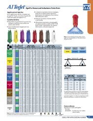
Air Induction Flat Spray TipsTypical Applications:See selection guide on page 2 forrecommended typical applicationsfor AI <strong>TeeJet</strong> tips.Features:n Stainless steel insert produces a taperededge flat spray pattern for uniformcoverage in broadcast spraying.n Polymer insert holder and pre-orificewith VisiFlo® color-coding.n Larger droplets for less drift.n Available in eight capacities witha recommended pressure rating30–115 PSI (2–8 bar).n Depending on the chemical, produceslarge air-filled drops through the useof a Venturi air aspirator.n Automatic spray alignment with25598-*-NYR Quick <strong>TeeJet</strong>® capand gasket. Reference page 57for more information.AI80015AI110015(100)AI8002AI11002(50)AI80025AI110025(50)AI8003AI11003(50)AI8004AI11004(50)AI8005AI11005(50)AI8006AI11006(50)AI11008(50)barDropSizecapacityonenozzlein l/min4km/h5km/h6km/h7km/h8km/h110º2.0 UC 0.48 144 115 96.0 82.3 72.0 57.6 48.0 36.0 32.0 28.8 23.0 19.2 16.53.0 XC 0.59 177 142 118 101 88.5 70.8 59.0 44.3 39.3 35.4 28.3 23.6 20.24.0 XC 0.68 204 163 136 117 102 81.6 68.0 <strong>51</strong>.0 45.3 40.8 32.6 27.2 23.35.0 VC 0.76 228 182 152 130 114 91.2 76.0 57.0 50.7 45.6 36.5 30.4 26.16.0 VC 0.83 249 199 166 142 125 99.6 83.0 62.3 55.3 49.8 39.8 33.2 28.57.0 C 0.90 270 216 180 154 135 108 90.0 67.5 60.0 54.0 43.2 36.0 30.98.0 C 0.96 288 230 192 165 144 115 96.0 72.0 64.0 57.6 46.1 38.4 32.92.0 UC 0.65 195 156 130 111 97.5 78.0 65.0 48.8 43.3 39.0 31.2 26.0 22.33.0 XC 0.79 237 190 158 135 119 94.8 79.0 59.3 52.7 47.4 37.9 31.6 27.14.0 XC 0.91 273 218 182 156 137 109 91.0 68.3 60.7 54.6 43.7 36.4 31.25.0 VC 1.02 306 245 204 175 153 122 102 76.5 68.0 61.2 49.0 40.8 35.06.0 VC 1.12 336 269 224 192 168 134 112 84.0 74.7 67.2 53.8 44.8 38.47.0 C 1.21 363 290 242 207 182 145 121 90.8 80.7 72.6 58.1 48.4 41.58.0 C 1.29 387 310 258 221 194 155 129 96.8 86.0 77.4 61.9 <strong>51</strong>.6 44.22.0 UC 0.81 243 194 162 139 122 97.2 81.0 60.8 54.0 48.6 38.9 32.4 27.83.0 XC 0.99 297 238 198 170 149 119 99.0 74.3 66.0 59.4 47.5 39.6 33.94.0 XC 1.14 342 274 228 195 171 137 114 85.5 76.0 68.4 54.7 45.6 39.15.0 VC 1.28 384 307 256 219 192 154 128 96.0 85.3 76.8 61.4 <strong>51</strong>.2 43.96.0 VC 1.40 420 336 280 240 210 168 140 105 93.3 84.0 67.2 56.0 48.07.0 C 1.<strong>51</strong> 453 362 302 259 227 181 1<strong>51</strong> 113 101 90.6 72.5 60.4 <strong>51</strong>.88.0 C 1.62 486 389 324 278 243 194 162 122 108 97.2 77.8 64.8 55.52.0 UC 0.96 288 230 192 165 144 115 96.0 72.0 64.0 57.6 46.1 38.4 32.93.0 XC 1.18 354 283 236 202 177 142 118 88.5 78.7 70.8 56.6 47.2 40.54.0 XC 1.36 408 326 272 233 204 163 136 102 90.7 81.6 65.3 54.4 46.65.0 VC 1.52 456 365 304 261 228 182 152 114 101 91.2 73.0 60.8 52.16.0 VC 1.67 501 401 334 286 2<strong>51</strong> 200 167 125 111 100 80.2 66.8 57.37.0 C 1.80 540 432 360 309 270 216 180 135 120 108 86.4 72.0 61.78.0 C 1.93 579 463 386 331 290 232 193 145 129 116 92.6 77.2 66.22.0 UC 1.29 387 310 258 221 194 155 129 96.8 86.0 77.4 61.9 <strong>51</strong>.6 44.23.0 XC 1.58 474 379 316 271 237 190 158 119 105 94.8 75.8 63.2 54.24.0 XC 1.82 546 437 364 312 273 218 182 137 121 109 87.4 72.8 62.45.0 VC 2.04 612 490 408 350 306 245 204 153 136 122 97.9 81.6 69.96.0 VC 2.23 669 535 446 382 335 268 223 167 149 134 107 89.2 76.57.0 C 2.41 723 578 482 413 362 289 241 181 161 145 116 96.4 82.68.0 C 2.58 774 619 <strong>51</strong>6 442 387 310 258 194 172 155 124 103 88.52.0 UC 1.61 483 386 322 276 242 193 161 121 107 96.6 77.3 64.4 55.23.0 XC 1.97 591 473 394 338 296 236 197 148 131 118 94.6 78.8 67.54.0 XC 2.27 681 545 454 389 341 272 227 170 1<strong>51</strong> 136 109 90.8 77.85.0 VC 2.54 762 610 508 435 381 305 254 191 169 152 122 102 87.16.0 VC 2.79 837 670 558 478 419 335 279 209 186 167 134 112 95.77.0 C 3.01 903 722 602 <strong>51</strong>6 452 361 301 226 201 181 144 120 1038.0 C 3.22 966 773 644 552 483 386 322 242 215 193 155 129 1102.0 UC 1.94 582 466 388 333 291 233 194 146 129 116 93.1 77.6 66.53.0 XC 2.37 711 569 474 406 356 284 237 178 158 142 114 94.8 81.34.0 XC 2.74 822 658 548 470 411 329 274 206 183 164 132 110 93.95.0 XC 3.06 918 734 612 525 459 367 306 230 204 184 147 122 1056.0 VC 3.35 1005 804 670 574 503 402 335 2<strong>51</strong> 223 201 161 134 1157.0 VC 3.62 1086 869 724 621 543 434 362 272 241 217 174 145 1248.0 C 3.87 1161 929 774 663 581 464 387 290 258 232 186 155 1332.0 UC 2.58 774 619 <strong>51</strong>6 442 387 310 258 194 172 155 124 103 88.53.0 UC 3.16 948 758 632 542 474 379 316 237 211 190 152 126 1084.0 XC 3.65 1095 876 730 626 548 438 365 274 243 219 175 146 1255.0 XC 4.08 1224 979 816 699 612 490 408 306 272 245 196 163 1406.0 VC 4.47 1341 1073 894 766 671 536 447 335 298 268 215 179 1537.0 VC 4.83 1449 1159 966 828 725 580 483 362 322 290 232 193 1668.0 C 5.16 1548 1238 1032 885 774 619 <strong>51</strong>6 387 344 310 248 206 177l/ha10km/h12km/h50 cm16km/h18km/h20km/hNote: Always double check your application rates. Tabulations are based on spraying water at 70°F (21°C).See pages 124–140 for drop size classification, useful formulas and other information.25km/h30km/h35km/hNote: Due to the pre-orifice design,this tip is not compatible with the4193A check valve tip strainer.CONTACTProductSpacing80°110°SYSTEMICProductDRIFTManagementGood EXCELLENT EXCELLENTOptimum Spray Height50 cm75 cm50 cmSprayHeightHow to order:Specify tip number.Example:AI11004-VS – Stainless Steel withVisiFlo color-codingBROADCAST NOZZLES77
Air Induction Flat Spray TipsTypical Applications:See selection guide on page 2 forrecommended typical applicationsfor AIC <strong>TeeJet</strong> tips.Features:n Produces a 110° tapered edge flatspray pattern for uniform coveragein broadcast spraying applications.n Available with a polymer insertholder with stainless steel(015–15 capacities), ceramic(025–05 capacities) or polymer(02–10 capacities) inserts.n Larger droplets for less drift.n Depending on the chemical,produces large air-filled dropsthrough the use of a Venturi airaspirator.n AI <strong>TeeJet</strong> nozzle molded intoQuick <strong>TeeJet</strong>® cap providesautomatic spray alignment.n Includes tightly fitting washerthat stays put and assures agood seal.n Recommended pressure rating30–115 PSI (2–8 bar).8AIC110015(100)AIC11002(50)AIC110025(50)AIC11003(50)AIC11004(50)AIC11005(50)AIC11006(50)AIC11008(50)AIC11010AIC11015barDropSizecapacityonenozzlein l/min4km/h5km/h6km/h7km/h8km/h2.0 UC 0.48 144 115 96.0 82.3 72.0 57.6 48.0 36.0 32.0 28.8 23.0 19.2 16.53.0 XC 0.59 177 142 118 101 88.5 70.8 59.0 44.3 39.3 35.4 28.3 23.6 20.24.0 XC 0.68 204 163 136 117 102 81.6 68.0 <strong>51</strong>.0 45.3 40.8 32.6 27.2 23.35.0 VC 0.76 228 182 152 130 114 91.2 76.0 57.0 50.7 45.6 36.5 30.4 26.16.0 VC 0.83 249 199 166 142 125 99.6 83.0 62.3 55.3 49.8 39.8 33.2 28.57.0 C 0.90 270 216 180 154 135 108 90.0 67.5 60.0 54.0 43.2 36.0 30.98.0 C 0.96 288 230 192 165 144 115 96.0 72.0 64.0 57.6 46.1 38.4 32.92.0 UC 0.65 195 156 130 111 97.5 78.0 65.0 48.8 43.3 39.0 31.2 26.0 22.33.0 XC 0.79 237 190 158 135 119 94.8 79.0 59.3 52.7 47.4 37.9 31.6 27.14.0 XC 0.91 273 218 182 156 137 109 91.0 68.3 60.7 54.6 43.7 36.4 31.25.0 VC 1.02 306 245 204 175 153 122 102 76.5 68.0 61.2 49.0 40.8 35.06.0 VC 1.12 336 269 224 192 168 134 112 84.0 74.7 67.2 53.8 44.8 38.47.0 C 1.21 363 290 242 207 182 145 121 90.8 80.7 72.6 58.1 48.4 41.58.0 C 1.29 387 310 258 221 194 155 129 96.8 86.0 77.4 61.9 <strong>51</strong>.6 44.22.0 UC 0.81 243 194 162 139 122 97.2 81.0 60.8 54.0 48.6 38.9 32.4 27.83.0 XC 0.99 297 238 198 170 149 119 99.0 74.3 66.0 59.4 47.5 39.6 33.94.0 XC 1.14 342 274 228 195 171 137 114 85.5 76.0 68.4 54.7 45.6 39.15.0 VC 1.28 384 307 256 219 192 154 128 96.0 85.3 76.8 61.4 <strong>51</strong>.2 43.96.0 VC 1.40 420 336 280 240 210 168 140 105 93.3 84.0 67.2 56.0 48.07.0 C 1.<strong>51</strong> 453 362 302 259 227 181 1<strong>51</strong> 113 101 90.6 72.5 60.4 <strong>51</strong>.88.0 C 1.62 486 389 324 278 243 194 162 122 108 97.2 77.8 64.8 55.52.0 UC 0.96 288 230 192 165 144 115 96.0 72.0 64.0 57.6 46.1 38.4 32.93.0 XC 1.18 354 283 236 202 177 142 118 88.5 78.7 70.8 56.6 47.2 40.54.0 XC 1.36 408 326 272 233 204 163 136 102 90.7 81.6 65.3 54.4 46.65.0 VC 1.52 456 365 304 261 228 182 152 114 101 91.2 73.0 60.8 52.16.0 VC 1.67 501 401 334 286 2<strong>51</strong> 200 167 125 111 100 80.2 66.8 57.37.0 C 1.80 540 432 360 309 270 216 180 135 120 108 86.4 72.0 61.78.0 C 1.93 579 463 386 331 290 232 193 145 129 116 92.6 77.2 66.22.0 UC 1.29 387 310 258 221 194 155 129 96.8 86.0 77.4 61.9 <strong>51</strong>.6 44.23.0 XC 1.58 474 379 316 271 237 190 158 119 105 94.8 75.8 63.2 54.24.0 XC 1.82 546 437 364 312 273 218 182 137 121 109 87.4 72.8 62.45.0 VC 2.04 612 490 408 350 306 245 204 153 136 122 97.9 81.6 69.96.0 VC 2.23 669 535 446 382 335 268 223 167 149 134 107 89.2 76.57.0 C 2.41 723 578 482 413 362 289 241 181 161 145 116 96.4 82.68.0 C 2.58 774 619 <strong>51</strong>6 442 387 310 258 194 172 155 124 103 88.52.0 UC 1.61 483 386 322 276 242 193 161 121 107 96.6 77.3 64.4 55.23.0 XC 1.97 591 473 394 338 296 236 197 148 131 118 94.6 78.8 67.54.0 XC 2.27 681 545 454 389 341 272 227 170 1<strong>51</strong> 136 109 90.8 77.85.0 VC 2.54 762 610 508 435 381 305 254 191 169 152 122 102 87.16.0 VC 2.79 837 670 558 478 419 335 279 209 186 167 134 112 95.77.0 C 3.01 903 722 602 <strong>51</strong>6 452 361 301 226 201 181 144 120 1038.0 C 3.22 966 773 644 552 483 386 322 242 215 193 155 129 1102.0 UC 1.94 582 466 388 333 291 233 194 146 129 116 93.1 77.6 66.53.0 XC 2.37 711 569 474 406 356 284 237 178 158 142 114 94.8 81.34.0 XC 2.74 822 658 548 470 411 329 274 206 183 164 132 110 93.95.0 XC 3.06 918 734 612 525 459 367 306 230 204 184 147 122 1056.0 VC 3.35 1005 804 670 574 503 402 335 2<strong>51</strong> 223 201 161 134 1157.0 VC 3.62 1086 869 724 621 543 434 362 272 241 217 174 145 1248.0 C 3.87 1161 929 774 663 581 464 387 290 258 232 186 155 1332.0 UC 2.58 774 619 <strong>51</strong>6 442 387 310 258 194 172 155 124 103 88.53.0 UC 3.16 948 758 632 542 474 379 316 237 211 190 152 126 1084.0 XC 3.65 1095 876 730 626 548 438 365 274 243 219 175 146 1255.0 XC 4.08 1224 979 816 699 612 490 408 306 272 245 196 163 1406.0 VC 4.47 1341 1073 894 766 671 536 447 335 298 268 215 179 1537.0 VC 4.83 1449 1159 966 828 725 580 483 362 322 290 232 193 1668.0 C 5.16 1548 1238 1032 885 774 619 <strong>51</strong>6 387 344 310 248 206 1772.0 UC 3.23 969 775 646 554 485 388 323 242 215 194 155 129 1113.0 UC 3.95 1185 948 790 677 593 474 395 296 263 237 190 158 1354.0 XC 4.56 1368 1094 912 782 684 547 456 342 304 274 219 182 1565.0 XC 5.10 1530 1224 1020 874 765 612 <strong>51</strong>0 383 340 306 245 204 1756.0 VC 5.59 1677 1342 1118 958 839 671 559 419 373 335 268 224 1927.0 VC 6.03 1809 1447 1206 1034 905 724 603 452 402 362 289 241 2078.0 C 6.45 1935 1548 1290 1106 968 774 645 484 430 387 310 258 2212.0 UC 4.83 1449 1159 966 828 725 580 483 362 322 290 232 193 1663.0 UC 5.92 1776 1421 1184 1015 888 710 592 444 395 355 284 237 2034.0 XC 6.84 2052 1642 1368 1173 1026 821 684 <strong>51</strong>3 456 410 328 274 2355.0 XC 7.64 2292 1834 1528 1310 1146 917 764 573 509 458 367 306 2626.0 VC 8.37 2<strong>51</strong>1 2009 1674 1435 1256 1004 837 628 558 502 402 335 2877.0 VC 9.04 2712 2170 1808 1550 1356 1085 904 678 603 542 434 362 3108.0 C 9.67 2901 2321 1934 1658 14<strong>51</strong> 1160 967 725 645 580 464 387 332l/ha10km/h50 cm12km/h16km/h18km/h20km/hNote: Always double check your application rates. Tabulations are based on spraying water at 70°F (21°C).See pages 124–140 for drop size classification, useful formulas and other information.25km/h30km/h35km/hNote: Due to the pre-orifice design, this tip is notcompatible with the 4193A check valve tip strainer.CONTACTProductSpacing110°SYSTEMICProductOptimum Spray HeightDRIFTManagementGood EXCELLENT EXCELLENT50 cm50 cmHow to order:Specify tip number.Examples:AIC11004-VS – Stainless Steelwith VisiFlo®color-codingAIC11003-VP – Polymer withVisiFlo colorcodingAIC11003-VK – Ceramic withVisiFlo colorcodingSprayHeightBROADCAST NOZZLES
Flat Spray TipsTypical Applications:See selection guide on page 2 forrecommended typical applicationsfor Turbo <strong>TeeJet</strong> Induction tips.Features:n 110° wide angle, air induction, tapered flatspray tip pattern based on the patentedoutlet orifice design of the original Turbo<strong>TeeJet</strong>® nozzle.n Patented orifice design provides large,round passages to minimize plugging.n Depending on the chemical, produceslarge air-filled drops through a Venturiair aspirator resulting in less drift.n All polymer construction for excellentchemical and wear resistance.n Compact size to prevent tip damage.n Removable pre-orifice.n Ideal for use with automatic sprayercontrollers.RemovableInsertPre-OrificeMixingChamberTwo internalair inletsOne externalair inletExit Orifice with15° offset fromvertical positionTTI110___-VP Spray Tip(Cross Section View)Note: Due to pre-orifice design, this tip is not compatiblewith the 4193A check valve tip strainer.n Wide operating pressure range:15–100 PSI (1–7 bar).n Automatic alignment when used with25598-*-NYR Quick <strong>TeeJet</strong>® cap and gasket.See page 57 for additional information.TTI110015(100)TTI11002(50)TTI110025(50)TTI11003(50)TTI11004(50)TTI11005(50)TTI11006(50)barDropSizecapacityonenozzlein l/min4km/h5km/h6km/h7km/h8km/h1.0 UC 0.34 102 81.6 68.0 58.3 <strong>51</strong>.0 40.8 34.0 25.5 22.7 20.4 16.3 13.6 11.72.0 UC 0.48 144 115 96.0 82.3 72.0 57.6 48.0 36.0 32.0 28.8 23.0 19.2 16.53.0 UC 0.59 177 142 118 101 88.5 70.8 59.0 44.3 39.3 35.4 28.3 23.6 20.24.0 XC 0.68 204 163 136 117 102 81.6 68.0 <strong>51</strong>.0 45.3 40.8 32.6 27.2 23.35.0 XC 0.76 228 182 152 130 114 91.2 76.0 57.0 50.7 45.6 36.5 30.4 26.16.0 XC 0.83 249 199 166 142 125 99.6 83.0 62.3 55.3 49.8 39.8 33.2 28.57.0 XC 0.90 270 216 180 154 135 108 90.0 67.5 60.0 54.0 43.2 36.0 30.91.0 UC 0.46 138 110 92.0 78.9 69.0 55.2 46.0 34.5 30.7 27.6 22.1 18.4 15.82.0 UC 0.65 195 156 130 111 97.5 78.0 65.0 48.8 43.3 39.0 31.2 26.0 22.33.0 UC 0.79 237 190 158 135 119 94.8 79.0 59.3 52.7 47.4 37.9 31.6 27.14.0 UC 0.91 273 218 182 156 137 109 91.0 68.3 60.7 54.6 43.7 36.4 31.25.0 XC 1.02 306 245 204 175 153 122 102 76.5 68.0 61.2 49.0 40.8 35.06.0 XC 1.12 336 269 224 192 168 134 112 84.0 74.7 67.2 53.8 44.8 38.47.0 XC 1.21 363 290 242 207 182 145 121 90.8 80.7 72.6 58.1 48.4 41.<strong>51</strong>.0 UC 0.57 171 137 114 97.7 85.5 68.4 57.0 42.8 38.0 34.2 27.4 22.8 19.52.0 UC 0.81 243 194 162 139 122 97.2 81.0 60.8 54.0 48.6 38.9 32.4 27.83.0 UC 0.99 297 238 198 170 149 119 99.0 74.3 66.0 59.4 47.5 39.6 33.94.0 UC 1.14 342 274 228 195 171 137 114 85.5 76.0 68.4 54.7 45.6 39.15.0 XC 1.28 384 307 256 219 192 154 128 96.0 85.3 76.8 61.4 <strong>51</strong>.2 43.96.0 XC 1.40 420 336 280 240 210 168 140 105 93.3 84.0 67.2 56.0 48.07.0 XC 1.<strong>51</strong> 453 362 302 259 227 181 1<strong>51</strong> 113 101 90.6 72.5 60.4 <strong>51</strong>.81.0 UC 0.68 204 163 136 117 102 81.6 68.0 <strong>51</strong>.0 45.3 40.8 32.6 27.2 23.32.0 UC 0.96 288 230 192 165 144 115 96.0 72.0 64.0 57.6 46.1 38.4 32.93.0 UC 1.18 354 283 236 202 177 142 118 88.5 78.7 70.8 56.6 47.2 40.54.0 UC 1.36 408 326 272 233 204 163 136 102 90.7 81.6 65.3 54.4 46.65.0 XC 1.52 456 365 304 261 228 182 152 114 101 91.2 73.0 60.8 52.16.0 XC 1.67 501 401 334 286 2<strong>51</strong> 200 167 125 111 100 80.2 66.8 57.37.0 XC 1.80 540 432 360 309 270 216 180 135 120 108 86.4 72.0 61.71.0 UC 0.91 273 218 182 156 137 109 91.0 68.3 60.7 54.6 43.7 36.4 31.22.0 UC 1.29 387 310 258 221 194 155 129 96.8 86.0 77.4 61.9 <strong>51</strong>.6 44.23.0 UC 1.58 474 379 316 271 237 190 158 119 105 94.8 75.8 63.2 54.24.0 UC 1.82 546 437 364 312 273 218 182 137 121 109 87.4 72.8 62.45.0 XC 2.04 612 490 408 350 306 245 204 153 136 122 97.9 81.6 69.96.0 XC 2.23 669 535 446 382 335 268 223 167 149 134 107 89.2 76.57.0 XC 2.41 723 578 482 413 362 289 241 181 161 145 116 96.4 82.61.0 UC 1.14 342 274 228 195 171 137 114 85.5 76.0 68.4 54.7 45.6 39.12.0 UC 1.61 483 386 322 276 242 193 161 121 107 96.6 77.3 64.4 55.23.0 UC 1.97 591 473 394 338 296 236 197 148 131 118 94.6 78.8 67.54.0 UC 2.27 681 545 454 389 341 272 227 170 1<strong>51</strong> 136 109 90.8 77.85.0 XC 2.54 762 610 508 435 381 305 254 191 169 152 122 102 87.16.0 XC 2.79 837 670 558 478 419 335 279 209 186 167 134 112 95.77.0 XC 3.01 903 722 602 <strong>51</strong>6 452 361 301 226 201 181 144 120 1031.0 UC 1.37 411 329 274 235 206 164 137 103 91.3 82.2 65.8 54.8 47.02.0 UC 1.94 582 466 388 333 291 233 194 146 129 116 93.1 77.6 66.53.0 UC 2.37 711 569 474 406 356 284 237 178 158 142 114 94.8 81.34.0 UC 2.74 822 658 548 470 411 329 274 206 183 164 132 110 93.95.0 XC 3.06 918 734 612 525 459 367 306 230 204 184 147 122 1056.0 XC 3.35 1005 804 670 574 503 402 335 2<strong>51</strong> 223 201 161 134 1157.0 XC 3.62 1086 869 724 621 543 434 362 272 241 217 174 145 124l/ha10km/h12km/h50 cm16km/h18km/h20km/hNote: Always double check your application rates. Tabulations are based on spraying water at 70°F (21°C).See pages 124–140 for drop size classification, useful formulas and other information.25km/h30km/h35km/hCONTACTProductSpacing110°SYSTEMICProductOptimum Spray HeightDRIFTManagement— EXCELLENT EXCELLENT50 cm50 cmSprayHeightHow to order:Specify tip number.Example:TTI11004-VP – Polymer with VisiFlo®color-codingBROADCAST NOZZLES99
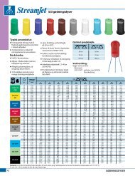
Extended Range Flat Spray TipsTypical Applications:See selection guide on page 2 forrecommended typical applicationsfor XR <strong>TeeJet</strong> tips.Features:n Excellent spray distribution over a widerange of pressures—15–60 PSI (1–4 bar).n Ideal for rigs equipped with sprayercontrollers.n Reduces drift at lower pressures, bettercoverage at higher pressures.n Available in stainless steel, ceramic andpolymer in 80° and 110° spray angles withVisiFlo® color-coding.n Ceramic is available with corrosiveresistantpolypropylene VisiFlo colorcodedtip holder in 80° capacities 03–08and 110° capacities 02–08.n XR110025 only available in VK.n Brass available in 110° only.n Automatic spray alignment with25612-*-NYR Quick <strong>TeeJet</strong>® cap and gasket.Reference page 57 for more information.n Automatic spray alignment for sizes 10and 15 with 25610-*-NYR Quick <strong>TeeJet</strong>cap and gasket. Reference page 57 formore information.At 15 PSI (1 bar)PressureAt 60 PSI (4 bar)PressureXR8001XR11001(100)XR80015XR110015(100)XR8002XR11002(50)XR110025(50)XR8003XR11003(50)XR8004XR11004(50)XR8005XR11005(50)XR8006XR11006(50)XR8008XR11008(50)XR8010†XR11010†XR8015†XR11015†barDropSize80º 110ºcapacityonenozzlein l/min4km/h5km/h6km/h7km/h8km/h1.0 M F 0.23 69.0 55.2 46.0 39.4 34.5 27.6 23.0 17.3 15.3 13.8 11.0 9.2 7.91.5 F F 0.28 84.0 67.2 56.0 48.0 42.0 33.6 28.0 21.0 18.7 16.8 13.4 11.2 9.62.0 F F 0.32 96.0 76.8 64.0 54.9 48.0 38.4 32.0 24.0 21.3 19.2 15.4 12.8 11.02.5 F F 0.36 108 86.4 72.0 61.7 54.0 43.2 36.0 27.0 24.0 21.6 17.3 14.4 12.33.0 F F 0.39 117 93.6 78.0 66.9 58.5 46.8 39.0 29.3 26.0 23.4 18.7 15.6 13.44.0 F VF 0.45 135 108 90.0 77.1 67.5 54.0 45.0 33.8 30.0 27.0 21.6 18.0 15.41.0 M F 0.34 102 81.6 68.0 58.3 <strong>51</strong>.0 40.8 34.0 25.5 22.7 20.4 16.3 13.6 11.71.5 M F 0.42 126 101 84.0 72.0 63.0 50.4 42.0 31.5 28.0 25.2 20.2 16.8 14.42.0 F F 0.48 144 115 96.0 82.3 72.0 57.6 48.0 36.0 32.0 28.8 23.0 19.2 16.52.5 F F 0.54 162 130 108 92.6 81.0 64.8 54.0 40.5 36.0 32.4 25.9 21.6 18.53.0 F F 0.59 177 142 118 101 88.5 70.8 59.0 44.3 39.3 35.4 28.3 23.6 20.24.0 F F 0.68 204 163 136 117 102 81.6 68.0 <strong>51</strong>.0 45.3 40.8 32.6 27.2 23.31.0 M M 0.46 138 110 92.0 78.9 69.0 55.2 46.0 34.5 30.7 27.6 22.1 18.4 15.81.5 M F 0.56 168 134 112 96.0 84.0 67.2 56.0 42.0 37.3 33.6 26.9 22.4 19.22.0 M F 0.65 195 156 130 111 97.5 78.0 65.0 48.8 43.3 39.0 31.2 26.0 22.32.5 M F 0.72 216 173 144 123 108 86.4 72.0 54.0 48.0 43.2 34.6 28.8 24.73.0 F F 0.79 237 190 158 135 119 94.8 79.0 59.3 52.7 47.4 37.9 31.6 27.14.0 F F 0.91 273 218 182 156 137 109 91.0 68.3 60.7 54.6 43.7 36.4 31.21.0 M 0.57 171 137 114 97.7 85.5 68.4 57.0 42.8 38.0 34.2 27.4 22.8 19.<strong>51</strong>.5 M 0.70 210 168 140 120 105 84.0 70.0 52.5 46.7 42.0 33.6 28.0 24.02.0 F 0.81 243 194 162 139 122 97.2 81.0 60.8 54.0 48.6 38.9 32.4 27.82.5 F 0.90 270 216 180 154 135 108 90.0 67.5 60.0 54.0 43.2 36.0 30.93.0 F 0.99 297 238 198 170 149 119 99.0 74.3 66.0 59.4 47.5 39.6 33.94.0 F 1.14 342 274 228 195 171 137 114 85.5 76.0 68.4 54.7 45.6 39.11.0 M M 0.68 204 163 136 117 102 81.6 68.0 <strong>51</strong>.0 45.3 40.8 32.6 27.2 23.31.5 M M 0.83 249 199 166 142 125 99.6 83.0 62.3 55.3 49.8 39.8 33.2 28.52.0 M F 0.96 288 230 192 165 144 115 96.0 72.0 64.0 57.6 46.1 38.4 32.92.5 M F 1.08 324 259 216 185 162 130 108 81.0 72.0 64.8 <strong>51</strong>.8 43.2 37.03.0 M F 1.18 354 283 236 202 177 142 118 88.5 78.7 70.8 56.6 47.2 40.54.0 M F 1.36 408 326 272 233 204 163 136 102 90.7 81.6 65.3 54.4 46.61.0 C M 0.91 273 218 182 156 137 109 91.0 68.3 60.7 54.6 43.7 36.4 31.21.5 M M 1.12 336 269 224 192 168 134 112 84.0 74.7 67.2 53.8 44.8 38.42.0 M M 1.29 387 310 258 221 194 155 129 96.8 86.0 77.4 61.9 <strong>51</strong>.6 44.22.5 M M 1.44 432 346 288 247 216 173 144 108 96.0 86.4 69.1 57.6 49.43.0 M M 1.58 474 379 316 271 237 190 158 119 105 94.8 75.8 63.2 54.24.0 M F 1.82 546 437 364 312 273 218 182 137 121 109 87.4 72.8 62.41.0 C C 1.14 342 274 228 195 171 137 114 85.5 76.0 68.4 54.7 45.6 39.11.5 C M 1.39 417 334 278 238 209 167 139 104 92.7 83.4 66.7 55.6 47.72.0 C M 1.61 483 386 322 276 242 193 161 121 107 96.6 77.3 64.4 55.22.5 M M 1.80 540 432 360 309 270 216 180 135 120 108 86.4 72.0 61.73.0 M M 1.97 591 473 394 338 296 236 197 148 131 118 94.6 78.8 67.54.0 M M 2.27 681 545 454 389 341 272 227 170 1<strong>51</strong> 136 109 90.8 77.81.0 C C 1.37 411 329 274 235 206 164 137 103 91.3 82.2 65.8 54.8 47.01.5 C C 1.68 504 403 336 288 252 202 168 126 112 101 80.6 67.2 57.62.0 C M 1.94 582 466 388 333 291 233 194 146 129 116 93.1 77.6 66.52.5 C M 2.16 648 <strong>51</strong>8 432 370 324 259 216 162 144 130 104 86.4 74.13.0 C M 2.37 711 569 474 406 356 284 237 178 158 142 114 94.8 81.34.0 C M 2.74 822 658 548 470 411 329 274 206 183 164 132 110 93.91.0 VC C 1.82 546 437 364 312 273 218 182 137 121 109 87.4 72.8 62.41.5 VC C 2.23 669 535 446 382 335 268 223 167 149 134 107 89.2 76.52.0 C C 2.58 774 619 <strong>51</strong>6 442 387 310 258 194 172 155 124 103 88.52.5 C C 2.88 864 691 576 494 432 346 288 216 192 173 138 115 98.73.0 C M 3.16 948 758 632 542 474 379 316 237 211 190 152 126 1084.0 C M 3.65 1095 876 730 626 548 438 365 274 243 219 175 146 12<strong>51</strong>.0 VC 2.28 684 547 456 391 342 274 228 171 152 137 109 91.2 78.21.5 VC 2.79 837 670 558 478 419 335 279 209 186 167 134 112 95.72.0 C 3.23 969 775 646 554 485 388 323 242 215 194 155 129 1112.5 C 3.61 1083 866 722 619 542 433 361 271 241 217 173 144 1243.0 C 3.95 1185 948 790 677 593 474 395 296 263 237 190 158 1354.0 M 4.56 1368 1094 912 782 684 547 456 342 304 274 219 182 1561.0 XC 3.42 1026 821 684 586 <strong>51</strong>3 410 342 257 228 205 164 137 1171.5 XC 4.19 1257 1006 838 718 629 503 419 314 279 2<strong>51</strong> 201 168 1442.0 VC 4.83 1449 1159 966 828 725 580 483 362 322 290 232 193 1662.5 C 5.40 1620 1296 1080 926 810 648 540 405 360 324 259 216 1853.0 C 5.92 1776 1421 1184 1015 888 710 592 444 395 355 284 237 2034.0 C 6.84 2052 1642 1368 1173 1026 821 684 <strong>51</strong>3 456 410 328 274 235l/ha10km/h12km/h50 cm16km/h18km/h20km/hNote: Always double check your application rates. Tabulations are based on spraying water at 70°F (21°C).See pages 124–140 for drop size classification, useful formulas and other information.†Available in all stainless steel only.25km/h30km/h35km/hCONTACTProductSpacingOptimum Spray Height80°110°SYSTEMICProductDRIFTManagementEXCELLENT Good GoodGood* VERY GOOD* VERY GOOD**At pressures below 30 PSI (2.0 bar)50 cm75 cm50 cmSprayHeightHow to order:Specify tip number.Examples:XR8004VS – Stainless Steel withVisiFlo color-codingXR11004-VP – Polymer with VisiFlocolor-coding (110º only)XR11004-VK – Ceramic withpolypropyleneVisiFlo colorcodingXR8010SS – Stainless SteelXR11004VB – Brass with VisiFlocolor-coding(110° only)10BROADCAST NOZZLES
Extended Range Flat Spray TipsTypical Applications:See selection guide on page 2 forrecommended typical applications forXRC <strong>TeeJet</strong> tips.Features:n Excellent spray distribution over a wide rangeof pressures—15–60 PSI (1–4 bar).n Ideal for rigs equipped with sprayer controllers.n Reduces drift at lower pressures, bettercoverage at higher pressures.n 80° available in stainless steel (015, 02, 03–06capacities) and ceramic (02, 03–08 capacities).n 110° available in stainless steel (025–05capacities), ceramic (02–08 capacities) andpolymer (025–20 capacities).n XR <strong>TeeJet</strong> tip molded into Quick <strong>TeeJet</strong>® capprovides automatic spray alignment.n Includes tightly fitting washer that stays putand assures a good seal.At 15 PSI (1 bar)PressureAt 60 PSI (4 bar)PressureXRC80015(100)XRC8002XRC11002(50)XRC110025(50)XRC8003XRC11003(50)XRC8004XRC11004(50)XRC8005XRC11005(50)XRC8006XRC11006(50)XRC8008XRC11008(50)XRC11010XRC11015XRC11020barDropSize80º 110ºcapacityonenozzlein l/min4km/h5km/h6km/h7km/h8km/h1.0 M 0.34 102 81.6 68.0 58.3 <strong>51</strong>.0 40.8 34.0 25.5 22.7 20.4 16.3 13.6 11.71.5 M 0.42 126 101 84.0 72.0 63.0 50.4 42.0 31.5 28.0 25.2 20.2 16.8 14.42.0 F 0.48 144 115 96.0 82.3 72.0 57.6 48.0 36.0 32.0 28.8 23.0 19.2 16.53.0 F 0.59 177 142 118 101 88.5 70.8 59.0 44.3 39.3 35.4 28.3 23.6 20.24.0 F 0.68 204 163 136 117 102 81.6 68.0 <strong>51</strong>.0 45.3 40.8 32.6 27.2 23.31.0 M M 0.46 138 110 92.0 78.9 69.0 55.2 46.0 34.5 30.7 27.6 22.1 18.4 15.81.5 M F 0.56 168 134 112 96.0 84.0 67.2 56.0 42.0 37.3 33.6 26.9 22.4 19.22.0 M F 0.65 195 156 130 111 97.5 78.0 65.0 48.8 43.3 39.0 31.2 26.0 22.33.0 F F 0.79 237 190 158 135 119 94.8 79.0 59.3 52.7 47.4 37.9 31.6 27.14.0 F F 0.91 273 218 182 156 137 109 91.0 68.3 60.7 54.6 43.7 36.4 31.21.0 M 0.57 171 137 114 97.7 85.5 68.4 57.0 42.8 38.0 34.2 27.4 22.8 19.<strong>51</strong>.5 M 0.70 210 168 140 120 105 84.0 70.0 52.5 46.7 42.0 33.6 28.0 24.02.0 F 0.81 243 194 162 139 122 97.2 81.0 60.8 54.0 48.6 38.9 32.4 27.83.0 F 0.99 297 238 198 170 149 119 99.0 74.3 66.0 59.4 47.5 39.6 33.94.0 F 1.14 342 274 228 195 171 137 114 85.5 76.0 68.4 54.7 45.6 39.11.0 M M 0.68 204 163 136 117 102 81.6 68.0 <strong>51</strong>.0 45.3 40.8 32.6 27.2 23.31.5 M M 0.83 249 199 166 142 125 99.6 83.0 62.3 55.3 49.8 39.8 33.2 28.52.0 M F 0.96 288 230 192 165 144 115 96.0 72.0 64.0 57.6 46.1 38.4 32.93.0 M F 1.18 354 283 236 202 177 142 118 88.5 78.7 70.8 56.6 47.2 40.54.0 M F 1.36 408 326 272 233 204 163 136 102 90.7 81.6 65.3 54.4 46.61.0 C M 0.91 273 218 182 156 137 109 91.0 68.3 60.7 54.6 43.7 36.4 31.21.5 M M 1.12 336 269 224 192 168 134 112 84.0 74.7 67.2 53.8 44.8 38.42.0 M M 1.29 387 310 258 221 194 155 129 96.8 86.0 77.4 61.9 <strong>51</strong>.6 44.23.0 M M 1.58 474 379 316 271 237 190 158 119 105 94.8 75.8 63.2 54.24.0 M F 1.82 546 437 364 312 273 218 182 137 121 109 87.4 72.8 62.41.0 C C 1.14 342 274 228 195 171 137 114 85.5 76.0 68.4 54.7 45.6 39.11.5 C M 1.39 417 334 278 238 209 167 139 104 92.7 83.4 66.7 55.6 47.72.0 C M 1.61 483 386 322 276 242 193 161 121 107 96.6 77.3 64.4 55.23.0 M M 1.97 591 473 394 338 296 236 197 148 131 118 94.6 78.8 67.54.0 M M 2.27 681 545 454 389 341 272 227 170 1<strong>51</strong> 136 109 90.8 77.81.0 C C 1.37 411 329 274 235 206 164 137 103 91.3 82.2 65.8 54.8 47.01.5 C C 1.68 504 403 336 288 252 202 168 126 112 101 80.6 67.2 57.62.0 C M 1.94 582 466 388 333 291 233 194 146 129 116 93.1 77.6 66.53.0 C M 2.37 711 569 474 406 356 284 237 178 158 142 114 94.8 81.34.0 C M 2.74 822 658 548 470 411 329 274 206 183 164 132 110 93.91.0 VC C 1.82 546 437 364 312 273 218 182 137 121 109 87.4 72.8 62.41.5 VC C 2.23 669 535 446 382 335 268 223 167 149 134 107 89.2 76.52.0 C C 2.58 774 619 <strong>51</strong>6 442 387 310 258 194 172 155 124 103 88.53.0 C M 3.16 948 758 632 542 474 379 316 237 211 190 152 126 1084.0 C M 3.65 1095 876 730 626 548 438 365 274 243 219 175 146 12<strong>51</strong>.0 VC 2.28 684 547 456 391 342 274 228 171 152 137 109 91.2 78.21.5 C 2.79 837 670 558 478 419 335 279 209 186 167 134 112 95.72.0 C 3.23 969 775 646 554 485 388 323 242 215 194 155 129 1113.0 C 3.95 1185 948 790 677 593 474 395 296 263 237 190 158 1354.0 M 4.56 1368 1094 912 782 684 547 456 342 304 274 219 182 1561.0 XC 3.42 1026 821 684 586 <strong>51</strong>3 410 342 257 228 205 164 137 1171.5 VC 4.19 1257 1006 838 718 629 503 419 314 279 2<strong>51</strong> 201 168 1442.0 VC 4.83 1449 1159 966 828 725 580 483 362 322 290 232 193 1663.0 C 5.92 1776 1421 1184 1015 888 710 592 444 395 355 284 237 2034.0 C 6.84 2052 1642 1368 1173 1026 821 684 <strong>51</strong>3 456 410 328 274 23<strong>51</strong>.0 XC 4.56 1368 1094 912 782 684 547 456 342 304 274 219 182 1561.5 XC 5.58 1674 1339 1116 957 837 670 558 419 372 335 268 223 1912.0 XC 6.44 1932 1546 1288 1104 966 773 644 483 429 386 309 258 2213.0 VC 7.89 2367 1894 1578 1353 1184 947 789 592 526 473 379 316 2714.0 VC 9.11 2733 2186 1822 1562 1367 1093 911 683 607 547 437 364 312l/ha10km/h12km/h50 cm16km/h18km/h20km/hNote: Always double check your application rates. Tabulations are based on spraying water at 70°F (21°C).See pages 124–140 for drop size classification, useful formulas and other information.BROADCAST NOZZLES25km/h30km/h35km/hCONTACTProductSpacing80°110°SYSTEMICProductOptimum Spray HeightDRIFTManagementEXCELLENT Good GoodGood* VERY GOOD* VERY GOOD**At pressures below 30 PSI (2.0 bar)50 cm75 cm50 cmSprayHeightHow to order:Specify tip number.Examples:XRC11004-VS – Stainless Steel withVisiFlo® color-codingXRC11004-VP – Polymer with VisiFlocolor-codingXRC11004-VK – Ceramic with VisiFlocolor-coding1111
VisiFlo® Flat Spray TipsFeatures:n Tapered edge flat spray pattern for uniformcoverage in broadcast spraying.n VisiFlo color-coded version available instainless steel, ceramic and polymer in80° or 110° spray angles in selected sizes.n Available in ceramic 80° capacities 01–02and 110° capacities 01–015. See XR andXRC <strong>TeeJet</strong>® tips on page 10–11 for largercapacities.n Standard version (not color-coded)available in 15°, 25°, 40°, 50° and 65°spray angles in brass, stainless steelor hardened stainless steel.n See page 31 for <strong>TeeJet</strong> even flat spray tips.n Automatic spray alignment with 25612-*-NYRQuick <strong>TeeJet</strong>® cap and gasket. Referencepage 57 for more information.n Automatic spray alignment for sizes10 through 20 with 25610-*-NYR Quick<strong>TeeJet</strong> cap and gasket. Reference page 57for more information.TP650050†TP800050†TP1100050†(100)TP650067†TP800067†TP1100067†(100)80º 110º2.0 0.16 48.0 38.4 32.0 27.4 24.0 19.2 16.0 12.0 10.7 9.6 7.7 6.4 5.52.5 0.18 54.0 43.2 36.0 30.9 27.0 21.6 18.0 13.5 12.0 10.8 8.6 7.2 6.23.0 0.20 60.0 48.0 40.0 34.3 30.0 24.0 20.0 15.0 13.3 12.0 9.6 8.0 6.93.5 0.22 66.0 52.8 44.0 37.7 33.0 26.4 22.0 16.5 14.7 13.2 10.6 8.8 7.54.0 0.23 69.0 55.2 46.0 39.4 34.5 27.6 23.0 17.3 15.3 13.8 11.0 9.2 7.92.0 0.21 63.0 50.4 42.0 36.0 31.5 25.2 21.0 15.8 14.0 12.6 10.1 8.4 7.22.5 0.24 72.0 57.6 48.0 41.1 36.0 28.8 24.0 18.0 16.0 14.4 11.5 9.6 8.23.0 0.26 78.0 62.4 52.0 44.6 39.0 31.2 26.0 19.5 17.3 15.6 12.5 10.4 8.93.5 0.28 84.0 67.2 56.0 48.0 42.0 33.6 28.0 21.0 18.7 16.8 13.4 11.2 9.6TP6501†4.0 0.30 90.0 72.0 60.0 <strong>51</strong>.4 45.0 36.0 30.0 22.5 20.0 18.0 14.4 12.0 10.32.0 F F 0.32 96.0 76.8 64.0 54.9 48.0 38.4 32.0 24.0 21.3 19.2 15.4 12.8 11.0TP8001 2.5 F F 0.36 108 86.4 72.0 61.7 54.0 43.2 36.0 27.0 24.0 21.6 17.3 14.4 12.33.0 F F 0.39 117 93.6 78.0 66.9 58.5 46.8 39.0 29.3 26.0 23.4 18.7 15.6 13.4TP110013.5 F VF 0.42 126 101 84.0 72.0 63.0 50.4 42.0 31.5 28.0 25.2 20.2 16.8 14.4(100) 4.0 F VF 0.45 135 108 90.0 77.1 67.5 54.0 45.0 33.8 30.0 27.0 21.6 18.0 15.4TP65015† 2.0 F F 0.48 144 115 96.0 82.3 72.0 57.6 48.0 36.0 32.0 28.8 23.0 19.2 16.5TP80015 2.5 F F 0.54 162 130 108 92.6 81.0 64.8 54.0 40.5 36.0 32.4 25.9 21.6 18.53.0 F F 0.59 177 142 118 101 88.5 70.8 59.0 44.3 39.3 35.4 28.3 23.6 20.2TP1100153.5 F F 0.64 192 154 128 110 96.0 76.8 64.0 48.0 42.7 38.4 30.7 25.6 21.9(100) 4.0 F F 0.68 204 163 136 117 102 81.6 68.0 <strong>51</strong>.0 45.3 40.8 32.6 27.2 23.3TP6502† 2.0 M F 0.65 195 156 130 111 97.5 78.0 65.0 48.8 43.3 39.0 31.2 26.0 22.3TP8002 2.5 M F 0.72 216 173 144 123 108 86.4 72.0 54.0 48.0 43.2 34.6 28.8 24.73.0 F F 0.79 237 190 158 135 119 94.8 79.0 59.3 52.7 47.4 37.9 31.6 27.1TP110023.5 F F 0.85 255 204 170 146 128 102 85.0 63.8 56.7 <strong>51</strong>.0 40.8 34.0 29.1(50) 4.0 F F 0.91 273 218 182 156 137 109 91.0 68.3 60.7 54.6 43.7 36.4 31.2TP6503† 2.0 M F 0.96 288 230 192 165 144 115 96.0 72.0 64.0 57.6 46.1 38.4 32.9TP8003 2.5 M F 1.08 324 259 216 185 162 130 108 81.0 72.0 64.8 <strong>51</strong>.8 43.2 37.03.0 M F 1.18 354 283 236 202 177 142 118 88.5 78.7 70.8 56.6 47.2 40.5TP110033.5 M F 1.27 381 305 254 218 191 152 127 95.3 84.7 76.2 61.0 50.8 43.5(50) 4.0 M F 1.36 408 326 272 233 204 163 136 102 90.7 81.6 65.3 54.4 46.6TP6504† 2.0 M M 1.29 387 310 258 221 194 155 129 96.8 86.0 77.4 61.9 <strong>51</strong>.6 44.2TP8004 2.5 M M 1.44 432 346 288 247 216 173 144 108 96.0 86.4 69.1 57.6 49.43.0 M M 1.58 474 379 316 271 237 190 158 119 105 94.8 75.8 63.2 54.2TP110043.5 M F 1.71 <strong>51</strong>3 410 342 293 257 205 171 128 114 103 82.1 68.4 58.6(50) 4.0 M F 1.82 546 437 364 312 273 218 182 137 121 109 87.4 72.8 62.4TP6505† 2.0 C M 1.61 483 386 322 276 242 193 161 121 107 96.6 77.3 64.4 55.2TP8005 2.5 M M 1.80 540 432 360 309 270 216 180 135 120 108 86.4 72.0 61.73.0 M M 1.97 591 473 394 338 296 236 197 148 131 118 94.6 78.8 67.5TP110053.5 M M 2.13 639 <strong>51</strong>1 426 365 320 256 213 160 142 128 102 85.2 73.0(50) 4.0 M M 2.27 681 545 454 389 341 272 227 170 1<strong>51</strong> 136 109 90.8 77.8TP6506† 2.0 C M 1.94 582 466 388 333 291 233 194 146 129 116 93.1 77.6 66.5TP8006 2.5 C M 2.16 648 <strong>51</strong>8 432 370 324 259 216 162 144 130 104 86.4 74.13.0 C M 2.37 711 569 474 406 356 284 237 178 158 142 114 94.8 81.3TP110063.5 C M 2.56 768 614 <strong>51</strong>2 439 384 307 256 192 171 154 123 102 87.8(50) 4.0 C M 2.74 822 658 548 470 411 329 274 206 183 164 132 110 93.9TP6508† 2.0 C C 2.58 774 619 <strong>51</strong>6 442 387 310 258 194 172 155 124 103 88.5TP8008TP11008(50)TP6<strong>51</strong>0†TP8010†TP11010†TP6<strong>51</strong>5†TP8015†TP11015†TP6520†TP8020†TP11020†barDropSizecapacityonenozzlein l/min4km/h5km/h6km/h7km/h8km/h2.5 C C 2.88 864 691 576 494 432 346 288 216 192 173 138 115 98.73.0 C M 3.16 948 758 632 542 474 379 316 237 211 190 152 126 1083.5 C M 3.41 1023 818 682 585 <strong>51</strong>2 409 341 256 227 205 164 136 1174.0 C M 3.65 1095 876 730 626 548 438 365 274 243 219 175 146 1252.0 3.23 969 775 646 554 485 388 323 242 215 194 155 129 1112.5 3.61 1083 866 722 619 542 433 361 271 241 217 173 144 1243.0 3.95 1185 948 790 677 593 474 395 296 263 237 190 158 1353.5 4.27 1281 1025 854 732 641 <strong>51</strong>2 427 320 285 256 205 171 1464.0 4.56 1368 1094 912 782 684 547 456 342 304 274 219 182 1562.0 4.83 1449 1159 966 828 725 580 483 362 322 290 232 193 1662.5 5.40 1620 1296 1080 926 810 648 540 405 360 324 259 216 1853.0 5.92 1776 1421 1184 1015 888 710 592 444 395 355 284 237 2033.5 6.39 1917 1534 1278 1095 959 767 639 479 426 383 307 256 2194.0 6.84 2052 1642 1368 1173 1026 821 684 <strong>51</strong>3 456 410 328 274 2352.0 6.44 1932 1546 1288 1104 966 773 644 483 429 386 309 258 2212.5 7.20 2160 1728 1440 1234 1080 864 720 540 480 432 346 288 2473.0 7.89 2367 1894 1578 1353 1184 947 789 592 526 473 379 316 2713.5 8.52 2556 2045 1704 1461 1278 1022 852 639 568 <strong>51</strong>1 409 341 2924.0 9.11 2733 2186 1822 1562 1367 1093 911 683 607 547 437 364 312Note: Always double check your application rates. Tabulations are based on spraying water at 70°F (21°C). See pages 124–140for drop size classification, useful formulas and other information.†Available in brass and/or stainless steel and/or hardened stainless steel.l/ha10km/h12km/h50 cm16km/h18km/h20km/h25km/h30km/h35km/hSpacingOptimum Spray Height65°80°110°50 cm90 cm75 cm50 cmSprayHeightHow to order:Specify tip number.Examples:TP8002VS – Stainless Steel withVisiFlo color-codingTP11002VP – Polymer with VisiFlocolor-codingTP11002-HSS – HardenedStainless SteelTP8002-SS – Stainless SteelTP8002 – Brass12BROADCAST NOZZLES
Drift Guard Flat Spray TipsRemovablePre-Orifice(Celcon®)Features:n Pre-orifice design produces larger dropletsand reduces the small drift-prone droplets,minimizing off-target spray contamination.n Tapered edge flat spray pattern providesuniform coverage when adjacent nozzlepatterns are overlapped in broadcastspraying.n The color-coded pre-orifice is removablefor any necessary cleaning operations.n Available in both 80° and 110° spray angleswith a durable stainless steel orifice.n Automatic spray alignment with 25612-*-NYRQuick <strong>TeeJet</strong>® cap and gasket. Referencepage 57 for more information.Tip Insert Holder(Celcon)Tip Insert(Stainless Steel)Drift Guard(Cross Section View)Note: Due to the pre-orifice design, this tip is notcompatible with the 4193A check valve tip strainer.SpacingDG80015†DG110015(100)DG8002†DG11002(50)DG8003†DG11003(50)DG8004†DG11004(50)DG8005†DG11005(50)barDropSize80º 110ºcapacityonenozzlein l/min4km/h5km/h6km/h7km/h8km/h2.0 M M 0.48 144 115 96.0 82.3 72.0 57.6 48.0 36.0 32.0 28.8 23.0 19.2 16.52.5 M F 0.54 162 130 108 92.6 81.0 64.8 54.0 40.5 36.0 32.4 25.9 21.6 18.53.0 M F 0.59 177 142 118 101 88.5 70.8 59.0 44.3 39.3 35.4 28.3 23.6 20.24.0 M F 0.68 204 163 136 117 102 81.6 68.0 <strong>51</strong>.0 45.3 40.8 32.6 27.2 23.35.0 F F 0.76 228 182 152 130 114 91.2 76.0 57.0 50.7 45.6 36.5 30.4 26.12.0 C M 0.65 195 156 130 111 97.5 78.0 65.0 48.8 43.3 39.0 31.2 26.0 22.32.5 M M 0.72 216 173 144 123 108 86.4 72.0 54.0 48.0 43.2 34.6 28.8 24.73.0 M M 0.79 237 190 158 135 119 94.8 79.0 59.3 52.7 47.4 37.9 31.6 27.14.0 M M 0.91 273 218 182 156 137 109 91.0 68.3 60.7 54.6 43.7 36.4 31.25.0 M M 1.02 306 245 204 175 153 122 102 76.5 68.0 61.2 49.0 40.8 35.02.0 C C 0.96 288 230 192 165 144 115 96.0 72.0 64.0 57.6 46.1 38.4 32.92.5 M M 1.08 324 259 216 185 162 130 108 81.0 72.0 64.8 <strong>51</strong>.8 43.2 37.03.0 M M 1.18 354 283 236 202 177 142 118 88.5 78.7 70.8 56.6 47.2 40.54.0 M M 1.36 408 326 272 233 204 163 136 102 90.7 81.6 65.3 54.4 46.65.0 M M 1.52 456 365 304 261 228 182 152 114 101 91.2 73.0 60.8 52.12.0 C C 1.29 387 310 258 221 194 155 129 96.8 86.0 77.4 61.9 <strong>51</strong>.6 44.22.5 C C 1.44 432 346 288 247 216 173 144 108 96.0 86.4 69.1 57.6 49.43.0 M M 1.58 474 379 316 271 237 190 158 119 105 94.8 75.8 63.2 54.24.0 M M 1.82 546 437 364 312 273 218 182 137 121 109 87.4 72.8 62.45.0 M M 2.04 612 490 408 350 306 245 204 153 136 122 97.9 81.6 69.92.0 C C 1.61 483 386 322 276 242 193 161 121 107 96.6 77.3 64.4 55.22.5 C C 1.80 540 432 360 309 270 216 180 135 120 108 86.4 72.0 61.73.0 C C 1.97 591 473 394 338 296 236 197 148 131 118 94.6 78.8 67.54.0 M M 2.27 681 545 454 389 341 272 227 170 1<strong>51</strong> 136 109 90.8 77.85.0 M M 2.54 762 610 508 435 381 305 254 191 169 152 122 102 87.1Note: Always double check your application rates. Tabulations are based on spraying water at 70°F (21°C). See pages 124–140for drop size classification, useful formulas and other information.†Available in VisiFlo stainless steel only.BROADCAST NOZZLESl/ha10km/h12km/h50 cm16km/h18km/h20km/h25km/h30km/h35km/hOptimum Spray Height80°110°50 cm75 cm50 cmSprayHeightHow to order:Specify tip number.Examples:DG8002VS – Stainless Steelwith VisiFlo®color-codingDG11002-VP – Polymer withVisiFlo color-coding1313
Twin Flat Spray TipsTypical Applications:See selection guide on page 2 forrecommended typical applicationsfor Turbo TwinJet tips.Features:n Dual outlet design produces two 110°flat fan spray patterns using the patentedtechnology from the Turbo <strong>TeeJet</strong>® nozzle.The angle between each spray pattern is60° forward and back.n Best suited for broadcast spraying wheresuperior leaf coverage and canopypenetration is important.n Droplet size range is slightly larger thanfor the same capacity Turbo <strong>TeeJet</strong> nozzleproviding drift-reducing properties withincreased canopy coverage and penetration.n Molded polymer for excellent chemicaland wear resistance.n Available in six VisiFlo® color-codedcapacities with pressure ranges from20–90 PSI (1.5–6 bar).n Ideal for use with automatic sprayercontrollers.n Automatic alignment when used with25612-*-NYR Quick <strong>TeeJet</strong>® cap and gasket.See page 57 for additional information.TTJ60-11002(100)TTJ60-110025(100)TTJ60-11003(100)TTJ60-11004(50)TTJ60-11005(50)TTJ60-11006(50)barDropSizecapacityonenozzlein l/min4km/h5km/h6km/h7km/h8km/h1.5 C 0.56 168 134 112 96.0 84.0 67.2 56.0 42.0 37.3 33.6 26.9 22.4 19.22.0 C 0.65 195 156 130 111 97.5 78.0 65.0 48.8 43.3 39.0 31.2 26.0 22.33.0 C 0.79 237 190 158 135 119 94.8 79.0 59.3 52.7 47.4 37.9 31.6 27.14.0 M 0.91 273 218 182 156 137 109 91.0 68.3 60.7 54.6 43.7 36.4 31.25.0 M 1.02 306 245 204 175 153 122 102 76.5 68.0 61.2 49.0 40.8 35.06.0 M 1.12 336 269 224 192 168 134 112 84.0 74.7 67.2 53.8 44.8 38.41.5 VC 0.70 210 168 140 120 105 84.0 70.0 52.5 46.7 42.0 33.6 28.0 24.02.0 C 0.81 243 194 162 139 122 97.2 81.0 60.8 54.0 48.6 38.9 32.4 27.83.0 C 0.99 297 238 198 170 149 119 99.0 74.3 66.0 59.4 47.5 39.6 33.94.0 C 1.14 342 274 228 195 171 137 114 85.5 76.0 68.4 54.7 45.6 39.15.0 M 1.28 384 307 256 219 192 154 128 96.0 85.3 76.8 61.4 <strong>51</strong>.2 43.96.0 M 1.40 420 336 280 240 210 168 140 105 93.3 84.0 67.2 56.0 48.01.5 VC 0.83 249 199 166 142 125 99.6 83.0 62.3 55.3 49.8 39.8 33.2 28.52.0 C 0.96 288 230 192 165 144 115 96.0 72.0 64.0 57.6 46.1 38.4 32.93.0 C 1.18 354 283 236 202 177 142 118 88.5 78.7 70.8 56.6 47.2 40.54.0 C 1.36 408 326 272 233 204 163 136 102 90.7 81.6 65.3 54.4 46.65.0 C 1.52 456 365 304 261 228 182 152 114 101 91.2 73.0 60.8 52.16.0 M 1.67 501 401 334 286 2<strong>51</strong> 200 167 125 111 100 80.2 66.8 57.31.5 VC 1.12 336 269 224 192 168 134 112 84.0 74.7 67.2 53.8 44.8 38.42.0 C 1.29 387 310 258 221 194 155 129 96.8 86.0 77.4 61.9 <strong>51</strong>.6 44.23.0 C 1.58 474 379 316 271 237 190 158 119 105 94.8 75.8 63.2 54.24.0 C 1.82 546 437 364 312 273 218 182 137 121 109 87.4 72.8 62.45.0 C 2.04 612 490 408 350 306 245 204 153 136 122 97.9 81.6 69.96.0 M 2.23 669 535 446 382 335 268 223 167 149 134 107 89.2 76.<strong>51</strong>.5 VC 1.39 417 334 278 238 209 167 139 104 92.7 83.4 66.7 55.6 47.72.0 C 1.61 483 386 322 276 242 193 161 121 107 96.6 77.3 64.4 55.23.0 C 1.97 591 473 394 338 296 236 197 148 131 118 94.6 78.8 67.54.0 C 2.27 681 545 454 389 341 272 227 170 1<strong>51</strong> 136 109 90.8 77.85.0 C 2.54 762 610 508 435 381 305 254 191 169 152 122 102 87.16.0 C 2.79 837 670 558 478 419 335 279 209 186 167 134 112 95.71.5 XC 1.68 504 403 336 288 252 202 168 126 112 101 80.6 67.2 57.62.0 VC 1.94 582 466 388 333 291 233 194 146 129 116 93.1 77.6 66.53.0 C 2.37 711 569 474 406 356 284 237 178 158 142 114 94.8 81.34.0 C 2.74 822 658 548 470 411 329 274 206 183 164 132 110 93.95.0 C 3.06 918 734 612 525 459 367 306 230 204 184 147 122 1056.0 C 3.35 1005 804 670 574 503 402 335 2<strong>51</strong> 223 201 161 134 115l/ha10km/h12km/h50 cm16km/h18km/h20km/hNote: Always double check your application rates. Tabulations are based on spraying water at 70°F (21°C).See pages 124–140 for drop size classification, useful formulas and other information.25km/h30km/h35km/hCONTACTProduct60°TTJ60-110___VP Spray Tip(Cross Section View)Spacing110°SYSTEMICProductOptimum Spray HeightDRIFTManagementEXCELLENT EXCELLENT Very GoodVery Good* EXCELLENT* EXCELLENT**At pressures below 30 PSI (2.0 bar)50 cm50 cmSprayHeightHow to order:Specify tip number.Example:TTJ60-11004VP – Polymer with VisiFlo®color-coding14BROADCAST NOZZLES
Twin Flat Spray TipsTypical Applications:See selection guide on page 2 forrecommended typical applicationsfor Air Induction Turbo TwinJet tips.Features:n Air induction with dual 110° flat fan patternsn 60° between leading and trailing spray patternsn Good coverage with increased canopypenetration and best drift controln Best suited for postemergence applicationsn Excellent drift control with coarse to verycoarse dropletsn Available in six VisiFlo® color coded capacities(02 through 06) – color represents total flown Pressure ranges from 20–90 PSI (1.5–6 bar)n Automatic spray alignment when used with25598-*-NYR Quick <strong>TeeJet</strong>® cap and gasket.See page 57 for additional information.RemovablePre-OrificeAITTJ60-11002VP(100)AITTJ60-110025VP(100)AITTJ60-11003VP(50)AITTJ60-11004VP(50)AITTJ60-11005VP(50)AITTJ60-11006VP(50)barDropSizecapacityonenozzlein l/min4km/h5km/h6km/h7km/h8km/hl/ha10km/h12km/h1.5 XC 0.56 168 134 112 96.0 84.0 67.2 56.0 42.0 37.3 33.6 26.9 22.4 19.22.0 VC 0.65 195 156 130 111 97.5 78.0 65.0 48.8 43.3 39.0 31.2 26.0 22.33.0 VC 0.79 237 190 158 135 119 94.8 79.0 59.3 52.7 47.4 37.9 31.6 27.14.0 C 0.91 273 218 182 156 137 109 91.0 68.3 60.7 54.6 43.7 36.4 31.25.0 C 1.02 306 245 204 175 153 122 102 76.5 68.0 61.2 49.0 40.8 35.06.0 C 1.12 336 269 224 192 168 134 112 84.0 74.7 67.2 53.8 44.8 38.41.5 XC 0.70 210 168 140 120 105 84.0 70.0 52.5 46.7 42.0 33.6 28.0 24.02.0 VC 0.81 243 194 162 139 122 97.2 81.0 60.8 54.0 48.6 38.9 32.4 27.83.0 VC 0.99 297 238 198 170 149 119 99.0 74.3 66.0 59.4 47.5 39.6 33.94.0 C 1.14 342 274 228 195 171 137 114 85.5 76.0 68.4 54.7 45.6 39.15.0 C 1.28 384 307 256 219 192 154 128 96.0 85.3 76.8 61.4 <strong>51</strong>.2 43.96.0 C 1.40 420 336 280 240 210 168 140 105 93.3 84.0 67.2 56.0 48.01.5 UC 0.83 249 199 166 142 125 99.6 83.0 62.3 55.3 49.8 39.8 33.2 28.52.0 XC 0.96 288 230 192 165 144 115 96.0 72.0 64.0 57.6 46.1 38.4 32.93.0 VC 1.18 354 283 236 202 177 142 118 88.5 78.7 70.8 56.6 47.2 40.54.0 VC 1.36 408 326 272 233 204 163 136 102 90.7 81.6 65.3 54.4 46.65.0 C 1.52 456 365 304 261 228 182 152 114 101 91.2 73.0 60.8 52.16.0 C 1.67 501 401 334 286 2<strong>51</strong> 200 167 125 111 100 80.2 66.8 57.31.5 UC 1.12 336 269 224 192 168 134 112 84.0 74.7 67.2 53.8 44.8 38.42.0 XC 1.29 387 310 258 221 194 155 129 96.8 86.0 77.4 61.9 <strong>51</strong>.6 44.23.0 VC 1.58 474 379 316 271 237 190 158 119 105 94.8 75.8 63.2 54.24.0 VC 1.82 546 437 364 312 273 218 182 137 121 109 87.4 72.8 62.45.0 C 2.04 612 490 408 350 306 245 204 153 136 122 97.9 81.6 69.96.0 C 2.23 669 535 446 382 335 268 223 167 149 134 107 89.2 76.<strong>51</strong>.5 UC 1.39 417 334 278 238 209 167 139 104 92.7 83.4 66.7 55.6 47.72.0 XC 1.61 483 386 322 276 242 193 161 121 107 96.6 77.3 64.4 55.23.0 XC 1.97 591 473 394 338 296 236 197 148 131 118 94.6 78.8 67.54.0 VC 2.27 681 545 454 389 341 272 227 170 1<strong>51</strong> 136 109 90.8 77.85.0 C 2.54 762 610 508 435 381 305 254 191 169 152 122 102 87.16.0 C 2.79 837 670 558 478 419 335 279 209 186 167 134 112 95.71.5 UC 1.68 504 403 336 288 252 202 168 126 112 101 80.6 67.2 57.62.0 XC 1.94 582 466 388 333 291 233 194 146 129 116 93.1 77.6 66.53.0 XC 2.37 711 569 474 406 356 284 237 178 158 142 114 94.8 81.34.0 VC 2.74 822 658 548 470 411 329 274 206 183 164 132 110 93.95.0 C 3.06 918 734 612 525 459 367 306 230 204 184 147 122 1056.0 C 3.35 1005 804 670 574 503 402 335 2<strong>51</strong> 223 201 161 134 11550 cm16km/h18km/h20km/hNote: Always double check your application rates. Tabulations are based on spraying water at 70°F (21°C).See pages 124–140 for drop size classification, useful formulas and other information.25km/h30km/h35km/hAir InletMixingChamberExitOrficeCONTACTProductAITTJ60-__VP Spray Tip(Cross Section View)SpacingOptimum Spray Height110°SYSTEMICProductDRIFTManagementGOOD EXCELLENT EXCELLENT50 cm50 cmTip BodyAir InletSprayHeightHow to order:Specify tip number.Example:AITTJ60-11004VP – Polymer with VisiFlo®color-codingBROADCAST NOZZLES1<strong>51</strong>5
Twin Flat Spray TipsTypical Applications:See selection guide on page 2 forrecommended typical applicationsfor TwinJet tips.Features:n Penetrates crop residue or dense foliage.n Smaller droplets for thorough coverage.n Better spray distribution along boom thanwith hollow cone nozzles.n Available in stainless steel with VisiFlo® colorcodingin 65°, 80° and 110° spray angles.n Recommended pressure rating30–60 PSI (2–4 bar).n See page 32 for TwinJet even flat spray tips.n Automatic spray alignment with25598-*-NYR Quick <strong>TeeJet</strong>® capand gasket. Reference page 57 formore information.n Reference technical section, pages 135–140for additional information on drift.16TJ60-6501TJ60-8001(100)TJ60-650134(100)TJ60-6502TJ60-8002TJ60-11002(100)TJ60-6503TJ60-8003TJ60-11003(100)TJ60-6504TJ60-8004TJ60-11004(50)TJ60-8005TJ60-11005(50)TJ60-6506TJ60-8006TJ60-11006(50)TJ60-6508TJ60-8008TJ60-11008(50)TJ60-8010TJ60-11010(50)barDropSize80º 110ºcapacityonenozzlein l/min4km/h5km/h6km/h7km/h8km/h2.0 VF 0.32 96.0 76.8 64.0 54.9 48.0 38.4 32.0 24.0 21.3 19.2 15.4 12.8 11.02.5 VF 0.36 108 86.4 72.0 61.7 54.0 43.2 36.0 27.0 24.0 21.6 17.3 14.4 12.33.0 VF 0.39 117 93.6 78.0 66.9 58.5 46.8 39.0 29.3 26.0 23.4 18.7 15.6 13.43.5 VF 0.42 126 101 84.0 72.0 63.0 50.4 42.0 31.5 28.0 25.2 20.2 16.8 14.44.0 VF 0.45 135 108 90.0 77.1 67.5 54.0 45.0 33.8 30.0 27.0 21.6 18.0 15.42.0 0.43 129 103 86.0 73.7 64.5 <strong>51</strong>.6 43.0 32.3 28.7 25.8 20.6 17.2 14.72.5 0.48 144 115 96.0 82.3 72.0 57.6 48.0 36.0 32.0 28.8 23.0 19.2 16.53.0 0.53 159 127 106 90.9 79.5 63.6 53.0 39.8 35.3 31.8 25.4 21.2 18.23.5 0.57 171 137 114 97.7 85.5 68.4 57.0 42.8 38.0 34.2 27.4 22.8 19.54.0 0.61 183 146 122 105 91.5 73.2 61.0 45.8 40.7 36.6 29.3 24.4 20.92.0 F F 0.65 195 156 130 111 97.5 78.0 65.0 48.8 43.3 39.0 31.2 26.0 22.32.5 F VF 0.72 216 173 144 123 108 86.4 72.0 54.0 48.0 43.2 34.6 28.8 24.73.0 F VF 0.79 237 190 158 135 119 94.8 79.0 59.3 52.7 47.4 37.9 31.6 27.13.5 F VF 0.85 255 204 170 146 128 102 85.0 63.8 56.7 <strong>51</strong>.0 40.8 34.0 29.14.0 F VF 0.91 273 218 182 156 137 109 91.0 68.3 60.7 54.6 43.7 36.4 31.22.0 F F 0.96 288 230 192 165 144 115 96.0 72.0 64.0 57.6 46.1 38.4 32.92.5 F F 1.08 324 259 216 185 162 130 108 81.0 72.0 64.8 <strong>51</strong>.8 43.2 37.03.0 F F 1.18 354 283 236 202 177 142 118 88.5 78.7 70.8 56.6 47.2 40.53.5 F F 1.27 381 305 254 218 191 152 127 95.3 84.7 76.2 61.0 50.8 43.54.0 F F 1.36 408 326 272 233 204 163 136 102 90.7 81.6 65.3 54.4 46.62.0 M F 1.29 387 310 258 221 194 155 129 96.8 86.0 77.4 61.9 <strong>51</strong>.6 44.22.5 M F 1.44 432 346 288 247 216 173 144 108 96.0 86.4 69.1 57.6 49.43.0 F F 1.58 474 379 316 271 237 190 158 119 105 94.8 75.8 63.2 54.23.5 F F 1.71 <strong>51</strong>3 410 342 293 257 205 171 128 114 103 82.1 68.4 58.64.0 F F 1.82 546 437 364 312 273 218 182 137 121 109 87.4 72.8 62.42.0 M M 1.61 483 386 322 276 242 193 161 121 107 96.6 77.3 64.4 55.22.5 M M 1.80 540 432 360 309 270 216 180 135 120 108 86.4 72.0 61.73.0 M F 1.97 591 473 394 338 296 236 197 148 131 118 94.6 78.8 67.53.5 F F 2.13 639 <strong>51</strong>1 426 365 320 256 213 160 142 128 102 85.2 73.04.0 F F 2.27 681 545 454 389 341 272 227 170 1<strong>51</strong> 136 109 90.8 77.82.0 M M 1.94 582 466 388 333 291 233 194 146 129 116 93.1 77.6 66.52.5 M M 2.16 648 <strong>51</strong>8 432 370 324 259 216 162 144 130 104 86.4 74.13.0 M M 2.37 711 569 474 406 356 284 237 178 158 142 114 94.8 81.33.5 M F 2.56 768 614 <strong>51</strong>2 439 384 307 256 192 171 154 123 102 87.84.0 M F 2.74 822 658 548 470 411 329 274 206 183 164 132 110 93.92.0 C M 2.58 774 619 <strong>51</strong>6 442 387 310 258 194 172 155 124 103 88.52.5 M M 2.88 864 691 576 494 432 346 288 216 192 173 138 115 98.73.0 M M 3.16 948 758 632 542 474 379 316 237 211 190 152 126 1083.5 M M 3.41 1023 818 682 585 <strong>51</strong>2 409 341 256 227 205 164 136 1174.0 M M 3.65 1095 876 730 626 548 438 365 274 243 219 175 146 1252.0 C M 3.23 969 775 646 554 485 388 323 242 215 194 155 129 1112.5 C M 3.61 1083 866 722 619 542 433 361 271 241 217 173 144 1243.0 C M 3.95 1185 948 790 677 593 474 395 296 263 237 190 158 1353.5 M M 4.27 1281 1025 854 732 641 <strong>51</strong>2 427 320 285 256 205 171 1464.0 M M 4.56 1368 1094 912 782 684 547 456 342 304 274 219 182 156l/ha10km/h50 cm12km/h16km/h18km/h20km/hNote: Always double check your application rates. Tabulations are based on spraying water at 70°F (21°C).See pages 124–140 for drop size classification, useful formulas and other information.25km/h30km/h35km/hCONTACTProductSpacingOptimum Spray Height65°80°110°How to order:Specify tip number.Example:TJ60-8002VSSYSTEMICProductDRIFTManagementEXCELLENT — —50 cm90 cm75 cm50 cmSprayHeight– Stainless Steel withVisiFlo color-codingBROADCAST NOZZLES
Dual Polymer Flat Fan Spray TipsFeatures:n Two Turbo <strong>TeeJet</strong> tapered edge flat fanspray tips using a QJ90-2-NYR adapterto produce a twin-type pattern sprayingforward and back. See page 5 for moreinformation on Turbo <strong>TeeJet</strong> spray tips.n Provides more versatility than the standardtwin-type spray tip. Depending on theTurbo <strong>TeeJet</strong> tip orientation, a 60°, 90°or 120° included angle can be achieved.n Best suited for broadcast spraying wheresuperior leaf coverage and canopypenetration is important.n QJ90 adapter and Quick <strong>TeeJet</strong>® capsare made of nylon. Turbo <strong>TeeJet</strong> tips aremade of Acetal for excellent wear lifeand chemical resistance. See page 58for additional information about theQJ90-2-NYR adapter.n Ideal for use with automaticsprayer controls.n Recommended operating pressurerange is 15–90 PSI (1–6 bar).n Quick <strong>TeeJet</strong> caps (included) are coloredto match the VisiFlo® color-coding of spraytips. See page 57 for additional information.QJ90-2XTT11001(100)QJ90-2XTT110015(100)QJ90-2XTT11002(50)QJ90-2XTT110025(50)QJ90-2XTT11003(50)QJ90-2XTT11004(50)QJ90-2XTT11005(50)QJ90-2XTT11006(50)QJ90-2XTT11008(50)barDropSizecapacityoneTT Duoin l/min4km/h5km/h6km/h7km/h8km/h1.0 C 0.46 138 110 92.0 78.9 69.0 55.2 46.0 34.5 30.7 27.6 22.1 18.4 15.82.0 M 0.65 195 156 130 111 97.5 78.0 65.0 48.8 43.3 39.0 31.2 26.0 22.33.0 F 0.79 237 190 158 135 119 94.8 79.0 59.3 52.7 47.4 37.9 31.6 27.14.0 F 0.91 273 218 182 156 137 109 91.0 68.3 60.7 54.6 43.7 36.4 31.25.0 F 1.02 306 245 204 175 153 122 102 76.5 68.0 61.2 49.0 40.8 35.06.0 F 1.12 336 269 224 192 168 134 112 84.0 74.7 67.2 53.8 44.8 38.41.0 C 0.68 204 163 136 117 102 81.6 68.0 <strong>51</strong>.0 45.3 40.8 32.6 27.2 23.32.0 M 0.96 288 230 192 165 144 115 96.0 72.0 64.0 57.6 46.1 38.4 32.93.0 M 1.18 354 283 236 202 177 142 118 88.5 78.7 70.8 56.6 47.2 40.54.0 M 1.36 408 326 272 233 204 163 136 102 90.7 81.6 65.3 54.4 46.65.0 F 1.52 456 365 304 261 228 182 152 114 101 91.2 73.0 60.8 52.16.0 F 1.67 501 401 334 286 2<strong>51</strong> 200 167 125 111 100 80.2 66.8 57.31.0 C 0.91 273 218 182 156 137 109 91.0 68.3 60.7 54.6 43.7 36.4 31.22.0 C 1.29 387 310 258 221 194 155 129 96.8 86.0 77.4 61.9 <strong>51</strong>.6 44.23.0 M 1.58 474 379 316 271 237 190 158 119 105 94.8 75.8 63.2 54.24.0 M 1.82 546 437 364 312 273 218 182 137 121 109 87.4 72.8 62.45.0 M 2.04 612 490 408 350 306 245 204 153 136 122 97.9 81.6 69.96.0 F 2.23 669 535 446 382 335 268 223 167 149 134 107 89.2 76.<strong>51</strong>.0 VC 1.14 342 274 228 195 171 137 114 85.5 76.0 68.4 54.7 45.6 39.12.0 C 1.61 483 386 322 276 242 193 161 121 107 96.6 77.3 64.4 55.23.0 M 1.97 591 473 394 338 296 236 197 148 131 118 94.6 78.8 67.54.0 M 2.27 681 545 454 389 341 272 227 170 1<strong>51</strong> 136 109 90.8 77.85.0 M 2.54 762 610 508 435 381 305 254 191 169 152 122 102 87.16.0 M 2.79 837 670 558 478 419 335 279 209 186 167 134 112 95.71.0 VC 1.37 411 329 274 235 206 164 137 103 91.3 82.2 65.8 54.8 47.02.0 C 1.94 582 466 388 333 291 233 194 146 129 116 93.1 77.6 66.53.0 C 2.37 711 569 474 406 356 284 237 178 158 142 114 94.8 81.34.0 M 2.74 822 658 548 470 411 329 274 206 183 164 132 110 93.95.0 M 3.06 918 734 612 525 459 367 306 230 204 184 147 122 1056.0 M 3.35 1005 804 670 574 503 402 335 2<strong>51</strong> 223 201 161 134 11<strong>51</strong>.0 XC 1.82 546 437 364 312 273 218 182 137 121 109 87.4 72.8 62.42.0 C 2.58 774 619 <strong>51</strong>6 442 387 310 258 194 172 155 124 103 88.53.0 C 3.16 948 758 632 542 474 379 316 237 211 190 152 126 1084.0 C 3.65 1095 876 730 626 548 438 365 274 243 219 175 146 1255.0 M 4.08 1224 979 816 699 612 490 408 306 272 245 196 163 1406.0 M 4.47 1341 1073 894 766 671 536 447 335 298 268 215 179 1531.0 XC 2.28 684 547 456 391 342 274 228 171 152 137 109 91.2 78.22.0 VC 3.23 969 775 646 554 485 388 323 242 215 194 155 129 1113.0 C 3.95 1185 948 790 677 593 474 395 296 263 237 190 158 1354.0 C 4.56 1368 1094 912 782 684 547 456 342 304 274 219 182 1565.0 C 5.10 1530 1224 1020 874 765 612 <strong>51</strong>0 383 340 306 245 204 1756.0 M 5.59 1677 1342 1118 958 839 671 559 419 373 335 268 224 1921.0 XC 2.74 822 658 548 470 411 329 274 206 183 164 132 110 93.92.0 VC 3.87 1161 929 774 663 581 464 387 290 258 232 186 155 1333.0 C 4.74 1422 1138 948 813 711 569 474 356 316 284 228 190 1634.0 C 5.47 1641 1313 1094 938 821 656 547 410 365 328 263 219 1885.0 C 6.12 1836 1469 1224 1049 918 734 612 459 408 367 294 245 2106.0 M 6.70 2010 1608 1340 1149 1005 804 670 503 447 402 322 268 2301.0 XC 3.65 1095 876 730 626 548 438 365 274 243 219 175 146 1252.0 VC 5.16 1548 1238 1032 885 774 619 <strong>51</strong>6 387 344 310 248 206 1773.0 C 6.32 1896 1<strong>51</strong>7 1264 1083 948 758 632 474 421 379 303 253 2174.0 C 7.30 2190 1752 1460 12<strong>51</strong> 1095 876 730 548 487 438 350 292 2505.0 C 8.16 2448 1958 1632 1399 1224 979 816 612 544 490 392 326 2806.0 M 8.94 2682 2146 1788 1533 1341 1073 894 671 596 536 429 358 307BROADCAST NOZZLESl/ha10km/h12km/h50 cm16km/h18km/h20km/hNote: Always double check your application rates. Tabulations are based on spraying water at 70°F (21°C).See pages 124–140 for drop size classification, useful formulas and other information.25km/h30km/h35km/hCONTACTProductSpacing110°SYSTEMICProductOptimum Spray HeightHow to order:Specify tip number.Example:QJ90-2XTT11004-VP –DRIFTManagementEXCELLENT EXCELLENT VERY GOODVERY GOOD* EXCELLENT* EXCELLENT**At pressures below 30 PSI (2.0 bar)50 cm50 cmSprayHeightPolymerwith VisiFlocolor-coding1717
Drift Guard Twin Flat Spray TipsTypical Applications:See selection guide on page 2 forrecommended typical applicationsfor DG TwinJet tips.Features:n Dual 110°, tapered edge, flat fan spraypatterns spraying 60° forward to backproviding uniform coverage in broadcastspraying applications.n DG TwinJet offers larger droplets andimproved drift control compared to astandard TwinJet spray tip of equal capacity.n Dual angled spray patterns help tobetter penetrate crop canopy andprovide thorough leaf coverage.n Made of stainless steel with VisiFlo®color-coding for excellent chemicaland wear resistance.n Removable polymer pre-orifice.n Available in six capacities with a recommendedpressure range of 30–60 PSI (2–4 bar).n Automatic spray alignment when used with25598-*-NYR Quick <strong>TeeJet</strong>® cap and gasket.Reference page 57 for more information.Pre-Orifice(Celcon)Tip Finish(StainlessSteelType 303)Tip Button(Celcon)DGTJ60-110015(100)DGTJ60-11002(100)DGTJ60-11003(100)DGTJ60-11004(50)DGTJ60-11006(50)DGTJ60-11008(50)barDropSizecapacityonenozzlein l/min4km/h5km/h6km/h7km/h2.0 F 0.48 144 115 96.0 82.3 72.0 57.6 48.0 36.0 32.0 28.8 23.0 19.2 16.52.5 F 0.54 162 130 108 92.6 81.0 64.8 54.0 40.5 36.0 32.4 25.9 21.6 18.53.0 F 0.59 177 142 118 101 88.5 70.8 59.0 44.3 39.3 35.4 28.3 23.6 20.23.5 F 0.64 192 154 128 110 96.0 76.8 64.0 48.0 42.7 38.4 30.7 25.6 21.94.0 F 0.68 204 163 136 117 102 81.6 68.0 <strong>51</strong>.0 45.3 40.8 32.6 27.2 23.32.0 M 0.65 195 156 130 111 97.5 78.0 65.0 48.8 43.3 39.0 31.2 26.0 22.32.5 M 0.72 216 173 144 123 108 86.4 72.0 54.0 48.0 43.2 34.6 28.8 24.73.0 F 0.79 237 190 158 135 119 94.8 79.0 59.3 52.7 47.4 37.9 31.6 27.13.5 F 0.85 255 204 170 146 128 102 85.0 63.8 56.7 <strong>51</strong>.0 40.8 34.0 29.14.0 F 0.91 273 218 182 156 137 109 91.0 68.3 60.7 54.6 43.7 36.4 31.22.0 C 0.96 288 230 192 165 144 115 96.0 72.0 64.0 57.6 46.1 38.4 32.92.5 M 1.08 324 259 216 185 162 130 108 81.0 72.0 64.8 <strong>51</strong>.8 43.2 37.03.0 M 1.18 354 283 236 202 177 142 118 88.5 78.7 70.8 56.6 47.2 40.53.5 M 1.27 381 305 254 218 191 152 127 95.3 84.7 76.2 61.0 50.8 43.54.0 M 1.36 408 326 272 233 204 163 136 102 90.7 81.6 65.3 54.4 46.62.0 C 1.29 387 310 258 221 194 155 129 96.8 86.0 77.4 61.9 <strong>51</strong>.6 44.22.5 C 1.44 432 346 288 247 216 173 144 108 96.0 86.4 69.1 57.6 49.43.0 C 1.58 474 379 316 271 237 190 158 119 105 94.8 75.8 63.2 54.23.5 C 1.71 <strong>51</strong>3 410 342 293 257 205 171 128 114 103 82.1 68.4 58.64.0 C 1.82 546 437 364 312 273 218 182 137 121 109 87.4 72.8 62.42.0 C 1.94 582 466 388 333 291 233 194 146 129 116 93.1 77.6 66.52.5 C 2.16 648 <strong>51</strong>8 432 370 324 259 216 162 144 130 104 86.4 74.13.0 C 2.37 711 569 474 406 356 284 237 178 158 142 114 94.8 81.33.5 C 2.56 768 614 <strong>51</strong>2 439 384 307 256 192 171 154 123 102 87.84.0 C 2.74 822 658 548 470 411 329 274 206 183 164 132 110 93.92.0 C 2.58 774 619 <strong>51</strong>6 442 387 310 258 194 172 155 124 103 88.52.5 C 2.88 864 691 576 494 432 346 288 216 192 173 138 115 98.73.0 C 3.16 948 758 632 542 474 379 316 237 211 190 152 126 1083.5 C 3.41 1023 818 682 585 <strong>51</strong>2 409 341 256 227 205 164 136 1174.0 C 3.65 1095 876 730 626 548 438 365 274 243 219 175 146 125Note: Always double check your application rates. Tabulations are based on spraying water at 70°F (21°C).See pages 124–140 for drop size classification, useful formulas and other information.8km/hl/ha10km/h12km/h50 cm16km/h18km/h20km/h25km/h30km/h35km/hDGTJ60-110___VS Spray Tip(Cross Section View)Note: Due to pre-orifice design, this tip is notcompatible with the 4193A check valve tip strainer.CONTACTProductSpacingOptimum Spray Height110°SYSTEMICProductDRIFTManagementVERY GOOD EXCELLENT VERY GOOD50 cm50 cmSprayHeightHow to order:Specify tip number.Example:DGTJ60-11004VS – Stainless Steel withVisiFlo color-coding18BROADCAST NOZZLES
Wide Angle Flat Spray TipsTypical Applications:See selection guide on page 2 forrecommended typical applicationsfor Turbo FloodJet tips.Features:n Excellent spray distribution for uniformcoverage along the boom.n Nozzle design incorporates a pre-orificeto produce larger droplets for less drift.n Large, round orifice reduces clogging.n Stainless steel or polymer withVisiFlo® color-coding band foreasy size identification.n Can be used with CP25600-*-NYRQuick <strong>TeeJet</strong>® cap and gasket forautomatic alignment. Referencepage 57 for more information.QCT Cam Lever Coupling Adaptern Provides easy change over from highcapacity to lower capacity nozzles.n Adapter fits standard 3/49 Cam levercoupling.n Corrosion-resistant stainless steeland polypropylene construction.n Rated up to 100 PSI (7 bar).n Use QJT-NYB to retrofit toQuick <strong>TeeJet</strong>.CP1325 CapTFVS TurboFloodJet®Spray TipQCTCam LeverCouplingAdapterCONTACTProductSYSTEMICProductDRIFTManagement— VERY GOOD EXCELLENTTF-†2(50)TF-†2.5(50)TF-†3(50)TF-†4(50)TF-†5(50)TF-†7.5(50)TF-†10(50)barDropSizecapacityonenozzlein l/min4km/h6km/hl/ha 75 cm l/ha 100 cm8km/h10km/h12km/h16km/h20km/h1.0 UC 0.91 182 121 91.0 72.8 60.7 45.5 36.4 29.1 137 91.0 68.3 54.6 45.5 34.1 27.3 21.81.5 XC 1.11 222 148 111 88.8 74.0 55.5 44.4 35.5 167 111 83.3 66.6 55.5 41.6 33.3 26.62.0 XC 1.29 258 172 129 103 86.0 64.5 <strong>51</strong>.6 41.3 194 129 96.8 77.4 64.5 48.4 38.7 31.02.5 XC 1.44 288 192 144 115 96.0 72.0 57.6 46.1 216 144 108 86.4 72.0 54.0 43.2 34.63.0 VC 1.58 316 211 158 126 105 79.0 63.2 50.6 237 158 119 94.8 79.0 59.3 47.4 37.91.0 UC 1.14 228 152 114 91.2 76.0 57.0 45.6 36.5 171 114 85.5 68.4 57.0 42.8 34.2 27.41.5 UC 1.40 280 187 140 112 93.3 70.0 56.0 44.8 210 140 105 84.0 70.0 52.5 42.0 33.62.0 XC 1.61 322 215 161 129 107 80.5 64.4 <strong>51</strong>.5 242 161 121 96.6 80.5 60.4 48.3 38.62.5 XC 1.80 360 240 180 144 120 90.0 72.0 57.6 270 180 135 108 90.0 67.5 54.0 43.23.0 XC 1.97 394 263 197 158 131 98.5 78.8 63.0 296 197 148 118 98.5 73.9 59.1 47.31.0 UC 1.37 274 183 137 110 91.3 68.5 54.8 43.8 206 137 103 82.2 68.5 <strong>51</strong>.4 41.1 32.91.5 UC 1.68 336 224 168 134 112 84.0 67.2 53.8 252 168 126 101 84.0 63.0 50.4 40.32.0 XC 1.94 388 259 194 155 129 97.0 77.6 62.1 291 194 146 116 97.0 72.8 58.2 46.62.5 XC 2.17 434 289 217 174 145 109 86.8 69.4 326 217 163 130 109 81.4 65.1 52.13.0 XC 2.37 474 316 237 190 158 119 94.8 75.8 356 237 178 142 119 88.9 71.1 56.91.0 UC 1.82 364 243 182 146 121 91.0 72.8 58.2 273 182 137 109 91.0 68.3 54.6 43.71.5 UC 2.23 446 297 223 178 149 112 89.2 71.4 335 223 167 134 112 83.6 66.9 53.52.0 UC 2.57 <strong>51</strong>4 343 257 206 171 129 103 82.2 386 257 193 154 129 96.4 77.1 61.72.5 XC 2.88 576 384 288 230 192 144 115 92.2 432 288 216 173 144 108 86.4 69.13.0 XC 3.15 630 420 315 252 210 158 126 101 473 315 236 189 158 118 94.5 75.61.0 UC 2.28 456 304 228 182 152 114 91.2 73.0 342 228 171 137 114 85.5 68.4 54.71.5 UC 2.79 558 372 279 223 186 140 112 89.3 419 279 209 167 140 105 83.7 67.02.0 UC 3.22 644 429 322 258 215 161 129 103 483 322 242 193 161 121 96.6 77.32.5 XC 3.60 720 480 360 288 240 180 144 115 540 360 270 216 180 135 108 86.43.0 XC 3.95 790 527 395 316 263 198 158 126 593 395 296 237 198 148 119 94.81.0 UC 3.42 684 456 342 274 228 171 137 109 <strong>51</strong>3 342 257 205 171 128 103 82.11.5 UC 4.19 838 559 419 335 279 210 168 134 629 419 314 2<strong>51</strong> 210 157 126 1012.0 UC 4.84 968 645 484 387 323 242 194 155 726 484 363 290 242 182 145 1162.5 XC 5.41 1082 721 541 433 361 271 216 173 812 541 406 325 271 203 162 1303.0 XC 5.92 1184 789 592 474 395 296 237 189 888 592 444 355 296 222 178 1421.0 UC 4.56 912 608 456 365 304 228 182 146 684 456 342 274 228 171 137 1091.5 UC 5.58 1116 744 558 446 372 279 223 179 837 558 419 335 279 209 167 1342.0 UC 6.45 1290 860 645 <strong>51</strong>6 430 323 258 206 968 645 484 387 323 242 194 1552.5 XC 7.21 1442 961 721 577 481 361 288 231 1082 721 541 433 361 270 216 1733.0 XC 7.90 1580 1053 790 632 527 395 316 253 1185 790 593 474 395 296 237 190BROADCAST NOZZLES25km/h4km/h6km/h8km/h10km/hNote: Always double check your application rates. Tabulations are based on spraying water at 70°F (21°C).See pages 124–140 for drop size classification, useful formulas and other information.†Specify material.12km/h16km/h20km/h25km/hSpacingOptimum Spray Height50 cm 60 cm*75 cm 75 cm*100 cm 100 cm**Wide angle spray nozzle height is influencedby nozzle orientation. The critical factoris to achieve a minimum 30% overlap.How to order:Specify tip number.Examples:TF-VS4 – Stainless Steel withVisiFlo color-codingTF-VP4 – Polymer with VisiFlocolor-codingSprayHeight19
Wide Angle Flat Fan Spray NozzlesTypical Applications:See selection guide on page 2 forrecommended typical applicationsfor Wide Angle Flat Fan Spray Nozzles.Features:n Can be used with Quick <strong>TeeJet</strong>®cap QJ4676-*-NYR.n Very large droplets.n Direct replacement for plastichollow-cone, low-drift nozzles.n More precise flow and distribution pattern.n Large orifice reduces clogging.n Nozzle spacing —20–409 (50–100 cm).n Spraying pressure —25–75 PSI (1.5–5 bar).QJ4676-90-1/4-NYRn 90° fitting attaches to Quick <strong>TeeJet</strong>bodies—1/49 female threaded outlet.n Simple installation of TurfJet nozzleson vertical nozzle bodies.n Nylon construction.QJ4676-90-1/4-NYRTurfJetSpray Nozzle221/4TTJ02(50)1/4TTJ04(50)1/4TTJ05(50)1/4TTJ06(50)1/4TTJ081/4TTJ101/4TTJ15barDropSizecapacityonenozzlein l/min4km/h5km/h6km/h7km/h1.5 UC 0.56 84.0 67.2 56.0 48.0 42.0 37.3 33.6 28.0 21.0 16.8 13.4 11.2 9.62.0 UC 0.65 97.5 78.0 65.0 55.7 48.8 43.3 39.0 32.5 24.4 19.5 15.6 13.0 11.13.0 XC 0.79 119 94.8 79.0 67.7 59.3 52.7 47.4 39.5 29.6 23.7 19.0 15.8 13.54.0 XC 0.91 137 109 91.0 78.0 68.3 60.7 54.6 45.5 34.1 27.3 21.8 18.2 15.65.0 XC 1.02 153 122 102 87.4 76.5 68.0 61.2 <strong>51</strong>.0 38.3 30.6 24.5 20.4 17.<strong>51</strong>.5 UC 1.12 168 134 112 96.0 84.0 74.7 67.2 56.0 42.0 33.6 26.9 22.4 19.22.0 UC 1.29 194 155 129 111 96.8 86.0 77.4 64.5 48.4 38.7 31.0 25.8 22.13.0 UC 1.58 237 190 158 135 119 105 94.8 79.0 59.3 47.4 37.9 31.6 27.14.0 UC 1.82 273 218 182 156 137 121 109 91.0 68.3 54.6 43.7 36.4 31.25.0 UC 2.04 306 245 204 175 153 136 122 102 76.5 61.2 49.0 40.8 35.01.5 UC 1.39 209 167 139 119 104 92.7 83.4 69.5 52.1 41.7 33.4 27.8 23.82.0 UC 1.61 242 193 161 138 121 107 96.6 80.5 60.4 48.3 38.6 32.2 27.63.0 UC 1.97 296 236 197 169 148 131 118 98.5 73.9 59.1 47.3 39.4 33.84.0 UC 2.27 341 272 227 195 170 1<strong>51</strong> 136 114 85.1 68.1 54.5 45.4 38.95.0 UC 2.54 381 305 254 218 191 169 152 127 95.3 76.2 61.0 50.8 43.<strong>51</strong>.5 UC 1.68 252 202 168 144 126 112 101 84.0 63.0 50.4 40.3 33.6 28.82.0 UC 1.94 291 233 194 166 146 129 116 97.0 72.8 58.2 46.6 38.8 33.33.0 UC 2.37 356 284 237 203 178 158 142 119 88.9 71.1 56.9 47.4 40.64.0 UC 2.74 411 329 274 235 206 183 164 137 103 82.2 65.8 54.8 47.05.0 UC 3.06 459 367 306 262 230 204 184 153 115 91.8 73.4 61.2 52.<strong>51</strong>.5 UC 2.23 335 268 223 191 167 149 134 112 83.6 66.9 53.5 44.6 38.22.0 UC 2.58 387 310 258 221 194 172 155 129 96.8 77.4 61.9 <strong>51</strong>.6 44.23.0 UC 3.16 474 379 316 271 237 211 190 158 119 94.8 75.8 63.2 54.24.0 UC 3.65 548 438 365 313 274 243 219 183 137 110 87.6 73.0 62.65.0 UC 4.08 612 490 408 350 306 272 245 204 153 122 97.9 81.6 69.91.5 UC 2.79 419 335 279 239 209 186 167 140 105 83.7 67.0 55.8 47.82.0 UC 3.23 485 388 323 277 242 215 194 162 121 96.9 77.5 64.6 55.43.0 UC 3.95 593 474 395 339 296 263 237 198 148 119 94.8 79.0 67.74.0 UC 4.56 684 547 456 391 342 304 274 228 171 137 109 91.2 78.25.0 UC 5.10 765 612 <strong>51</strong>0 437 383 340 306 255 191 153 122 102 87.41.5 UC 4.19 629 503 419 359 314 279 2<strong>51</strong> 210 157 126 101 83.8 71.82.0 UC 4.83 725 580 483 414 362 322 290 242 181 145 116 96.6 82.83.0 UC 5.92 888 710 592 507 444 395 355 296 222 178 142 118 1014.0 UC 6.84 1026 821 684 586 <strong>51</strong>3 456 410 342 257 205 164 137 1175.0 UC 7.64 1146 917 764 655 573 509 458 382 287 229 183 153 131Note: Always double check your application rates. Tabulations are based on spraying water at 70°F (21°C).See pages 124–140 for drop size classification, useful formulas and other information.8km/hl/ha9km/h10km/h100 cm12km/h16km/h20km/h25km/h30km/h35km/hCONTACTProductSpacingSYSTEMICProductOptimum Spray Height50 cm 60 cm*75 cm 75 cm*100 cm 100 cm*DRIFTManagement— EXCELLENT EXCELLENT*Wide angle spray nozzle height is influenced bynozzle orientation. The critical factor is to achievea minimum 30% overlap.How to order:Specify tip number.Examples:1/4TTJ04-VS – Stainless Steel withVisiFlo® color-coding1/4TTJ06-VP – Polymer with VisiFlocolor-codingSprayHeightBROADCAST NOZZLES
Double Outlet Flat Spray Tips150° SeriesStainless Steeland BrassSuggested for postdirectedapplicationwith hose drops.How to order:Specify tip number and material.Example: TQ150-03-SS –Stainless SteelTQ150-01-SS(100)TQ150-015-SS(100)TQ150-02-SS(100)TQ150-03-SS(100)TQ150-04-SS(50)TQ150-05-SS(50)TQ150-06-SS(50)TQ150-08-SS(50)TQ150-09-SS(50)barcapacityonenozzlein l/min4km/h6km/h8km/h1.5 0.28 84.0 56.0 42.0 33.6 28.0 24.0 21.0 18.72.0 0.32 96.0 64.0 48.0 38.4 32.0 27.4 24.0 21.32.5 0.36 108 72.0 54.0 43.2 36.0 30.9 27.0 24.03.0 0.39 117 78.0 58.5 46.8 39.0 33.4 29.3 26.03.5 0.42 126 84.0 63.0 50.4 42.0 36.0 31.5 28.01.5 0.42 126 84.0 63.0 50.4 42.0 36.0 31.5 28.02.0 0.48 144 96.0 72.0 57.6 48.0 41.1 36.0 32.02.5 0.54 162 108 81.0 64.8 54.0 46.3 40.5 36.03.0 0.59 177 118 88.5 70.8 59.0 50.6 44.3 39.33.5 0.64 192 128 96.0 76.8 64.0 54.9 48.0 42.71.5 0.56 168 112 84.0 67.2 56.0 48.0 42.0 37.32.0 0.65 195 130 97.5 78.0 65.0 55.7 48.8 43.32.5 0.72 216 144 108 86.4 72.0 61.7 54.0 48.03.0 0.79 237 158 119 94.8 79.0 67.7 59.3 52.73.5 0.85 255 170 128 102 85.0 72.9 63.8 56.71.5 0.83 249 166 125 99.6 83.0 71.1 62.3 55.32.0 0.96 288 192 144 115 96.0 82.3 72.0 64.02.5 1.08 324 216 162 130 108 92.6 81.0 72.03.0 1.18 354 236 177 142 118 101 88.5 78.73.5 1.27 381 254 191 152 127 109 95.3 84.71.5 1.12 336 224 168 134 112 96.0 84.0 74.72.0 1.29 387 258 194 155 129 111 96.8 86.02.5 1.44 432 288 216 173 144 123 108 96.03.0 1.58 474 316 237 190 158 135 119 1053.5 1.71 <strong>51</strong>3 342 257 205 171 147 128 1141.5 1.39 417 278 209 167 139 119 104 92.72.0 1.61 483 322 242 193 161 138 121 1072.5 1.80 540 360 270 216 180 154 135 1203.0 1.97 591 394 296 236 197 169 148 1313.5 2.13 639 426 320 256 213 183 160 1421.5 1.68 504 336 252 202 168 144 126 1122.0 1.94 582 388 291 233 194 166 146 1292.5 2.16 648 432 324 259 216 185 162 1443.0 2.37 711 474 356 284 237 203 178 1583.5 2.56 768 <strong>51</strong>2 384 307 256 219 192 1711.5 2.23 669 446 335 268 223 191 167 1492.0 2.58 774 <strong>51</strong>6 387 310 258 221 194 1722.5 2.88 864 576 432 346 288 247 216 1923.0 3.16 948 632 474 379 316 271 237 2113.5 3.41 1023 682 <strong>51</strong>2 409 341 292 256 2271.5 2.<strong>51</strong> 753 502 377 301 2<strong>51</strong> 215 188 1672.0 2.90 870 580 435 348 290 249 218 1932.5 3.24 972 648 486 389 324 278 243 2163.0 3.55 1065 710 533 426 355 304 266 2373.5 3.83 1149 766 575 460 383 328 287 255l/ha10km/h50 cm12km/h14km/hNote: Always double check your application rates. Tabulations are based on spraying water at 70°F (21°C).See pages 124–140 for useful formulas and other information.16km/h18km/hOff-Center Flat Spray Tips — Smaller Capacities<strong>TeeJet</strong> Off-Centerspray tips arecommonly installedin double and singleswivel nozzle bodies.Because these bodiesare adjustable for angularposition, a wide spray swathis easily obtained.See page 62 for swivelsand hose drops.How to order:Specify tip number and material.Example: OC-02 – BrassOC-SS06 – Stainless SteelHBROADCAST NOZZLESWOC-01(100)OC-02(50)OC-03(50)OC-04(50)OC-06(50)OC-08(50)OC-12OC-16barcapacityonenozzlein l/min“W”cmHeight = 45 cmHeight = 60 cml/ha“W”l/ha4 km/h 6 km/h 8 km/h 10 km/h cm 4 km/h 6 km/h 8 km/h 10 km/h2.0 0.32 147 32.7 21.8 16.3 13.1 165 29.1 19.4 14.5 11.63.0 0.39 152 38.5 25.7 19.2 15.4 170 34.4 22.9 17.2 13.84.0 0.45 157 43.0 28.7 21.5 17.2 175 38.6 25.7 19.3 15.42.0 0.65 172 56.7 37.8 28.3 22.7 190 <strong>51</strong>.3 34.2 25.7 20.53.0 0.79 177 66.9 44.6 33.5 26.8 195 60.8 40.5 30.4 24.34.0 0.91 182 75.0 50.0 37.5 30.0 198 68.9 46.0 34.5 27.62.0 0.96 195 73.8 49.2 36.9 29.5 203 70.9 47.3 35.5 28.43.0 1.18 203 87.2 58.1 43.6 34.9 210 84.3 56.2 42.1 33.74.0 1.36 208 98.1 65.4 49.0 39.2 215 94.9 63.3 47.4 38.02.0 1.29 231 83.8 55.8 41.9 33.5 236 82.0 54.7 41.0 32.83.0 1.58 236 100 66.9 50.2 40.2 238 99.6 66.4 49.8 39.84.0 1.82 238 115 76.5 57.4 45.9 241 113 75.5 56.6 45.32.0 1.94 2<strong>51</strong> 116 77.3 58.0 46.4 274 106 70.8 53.1 42.53.0 2.37 256 139 92.6 69.4 55.5 279 127 84.9 63.7 <strong>51</strong>.04.0 2.74 259 159 106 79.3 63.5 281 146 97.5 73.1 58.52.0 2.58 254 152 102 76.2 60.9 279 139 92.5 69.4 55.53.0 3.16 259 183 122 91.5 73.2 284 167 111 83.5 66.84.0 3.65 264 207 138 104 83.0 287 191 127 95.4 76.32.0 3.87 259 224 149 112 89.7 287 202 135 101 80.93.0 4.74 264 269 180 135 108 292 243 162 122 97.44.0 5.47 266 308 206 154 123 294 279 186 140 1122.0 5.16 335 231 154 116 92.4 360 215 143 108 86.03.0 6.32 350 271 181 135 108 370 256 171 128 1024.0 7.30 363 302 201 1<strong>51</strong> 121 375 292 195 146 117Note: Always double check your application rates. Tabulations are based on spraying water at 70°F (21°C).See pages 124–140 for useful formulas and other information.2323
Wide Angle Full Cone Spray TipsFeatures:n Large droplets to reduce drift.n Excellent spray distribution over a range ofpressures 15–40 PSI (1–3 bar).n Ideal for use on rigs with sprayer controllers.n Wide spray angle allows use on 409(100 cm) spacings.n Available in VisiFlo® color-codingsystem in all stainless steel or Celcon®with stainless steel vane.n Can be used with CP25607-*-NY for Quick<strong>TeeJet</strong>® connection. Reference page 57 formore information.SpacingSprayHeightOptimum Spray Height50 cm 50 cm*FL-5VSFL-5VCFL-6.5VSFL-6.5VCFL-8VSFL-8VCFL-10VSFL-10VCFL-15VSFL-15VCbarcapacityonenozzlein l/min4km/h6km/hl/ha 50 cm l/ha 100cm8km/h10km/h15km/h20km/h4km/h6km/h8km/h10km/h15km/h20km/h1.0 1.19 357 238 179 143 95 71 179 119 89 71 48 361.5 1.43 429 286 215 172 114 86 215 143 107 86 57 432.0 1.69 507 338 254 203 135 101 254 169 127 101 68 <strong>51</strong>2.5 1.81 543 362 272 217 145 109 272 181 136 109 72 543.0 1.97 591 394 296 236 158 118 296 197 148 118 79 591.0 1.56 468 312 234 187 125 94 234 156 117 94 62 471.5 1.89 567 378 284 227 1<strong>51</strong> 113 284 189 142 113 76 572.0 2.14 642 428 321 257 171 128 321 214 161 128 86 642.5 2.34 702 468 3<strong>51</strong> 281 187 140 3<strong>51</strong> 234 176 140 94 703.0 2.56 768 <strong>51</strong>2 384 307 205 154 384 256 192 154 102 771.0 1.90 570 380 285 228 152 114 285 190 143 114 76 571.5 2.29 687 458 344 275 183 137 344 229 172 137 92 692.0 2.60 780 520 390 312 208 156 390 260 195 156 104 782.5 2.89 867 578 434 347 231 173 434 289 217 173 116 873.0 3.15 945 630 473 378 252 189 473 315 236 189 126 9<strong>51</strong>.0 2.37 711 474 356 284 190 142 356 237 178 142 95 711.5 2.86 858 572 429 343 229 172 429 286 215 172 114 862.0 3.39 1017 678 509 407 271 203 509 339 254 203 136 1022.5 3.62 1086 724 543 434 290 217 543 362 272 217 145 1093.0 3.93 1179 786 590 472 314 236 590 393 295 236 157 1181.0 3.56 1068 712 534 427 285 214 534 356 267 214 142 1071.5 4.29 1287 858 644 <strong>51</strong>5 343 257 644 429 322 257 172 1292.0 4.84 1452 968 726 581 387 290 726 484 363 290 194 1452.5 5.43 1629 1086 815 652 434 326 815 543 407 326 217 1633.0 5.90 1770 1180 885 708 472 354 885 590 443 354 236 177Note: Always double check your application rates. Tabulations are based on spraying water at 70°F (21°C).See pages 124–140 for useful formulas and other information.75 cm 75 cm*100 cm 100 cm*FullJet nozzles should be angled 30°–45° from vertical foruniform spray distribution.*Wide angle spray nozzle height is influenced by nozzleorientation. The critical factor is to achieve a minimum30% overlap.45ºSide ViewHow to order:Specify tip number.Examples:FL-5VS – Stainless Steel with VisiFlocolor-codingFL-5VC – Celcon with Stainless Steelvane and VisiFlo color-coding24BROADCAST NOZZLES
Typical Applications:n Boomless field spray applications.n Roadside and right-of-way applications.n End row spraying.n Orchard spraying.n De-icing applications.n Forestry.Boomless Flat Spray NozzlesFeatures:n Unique orifice geometry produces a widespray pattern while maintaining superiordistribution across entire width.n Pre-orifice design minimizes drift.n Extra wide spray pattern—up to 18.58(5.5 meters)—using a single nozzle.n Removable polymer pre-orifice.n Acetal or stainless steel construction forexcellent chemical resistance.n Recommended spray pressure range:20–60 PSI (1.5–4 bar).“Y”n NPT or BSPT (male) threads for easyinstallation.n Color-coding for easy capacity identification.n 10 capacity only available in VPMounting Note: Position tip horizontal to groundwith spray pattern down and to the side.How to order:Specify part number. Example:(B)1/2XP80L(R)-VS –VisiFlo® Stainless Steel left boom spray“X” “X”“L” “C” “R”l/ha for THREE nozzles“W”“R”, “L”Centernozzle“C”barDropSizecapacityThreenozzlesin l/minspray width“w” (meters)60 cmheight90 cmheight4km/h8km/hheight “Y” = 60 cm12km/h(B)1/4XP10R2.0 UC 9.04 7.0 7.8 194 96.9 64.6 48.4 32.3 24.2 174 86.9 57.9 43.5 29.0 21.7(B)1/4XP10L 1/4TTJ08 3.0 UC 11.1 7.8 8.6 213 107 71.2 53.4 35.6 26.7 194 96.8 64.5 48.4 32.3 24.23.5 UC 12.2 8.6 9.2 213 106 70.9 53.2 35.5 26.6 199 99.5 66.3 49.7 33.2 24.91.5 UC 7.85 6.2 7.0 190 95.0 63.3 47.5 31.7 23.7 168 84.1 56.1 42.1 28.0 21.04.0 UC 13.2 9.0 9.8 220 110 73.3 55.0 36.7 27.5 202 101 67.3 50.5 33.7 25.3(B)1/4XP20R2.0 UC 15.4 8.0 8.4 289 144 96.3 72.2 48.1 36.1 275 138 91.7 68.8 45.8 34.4(B)1/4XP20L 1/4TTJ08 3.0 UC 18.9 9.2 9.6 308 154 103 77.0 <strong>51</strong>.4 38.5 295 148 98.4 73.8 49.2 36.93.5 UC 20.7 9.8 10.2 317 158 106 79.2 52.8 39.6 304 152 101 76.1 50.7 38.11.5 UC 13.4 6.4 7.8 314 157 105 78.5 52.3 39.3 258 129 85.9 64.4 42.9 32.24.0 UC 22.3 10.2 10.8 328 164 109 82.0 54.7 41.0 310 155 103 77.4 <strong>51</strong>.6 38.7(B)1/4XP25R2.0 UC 19.1 8.4 9.2 341 171 114 85.3 56.8 42.6 311 156 104 77.9 <strong>51</strong>.9 38.9(B)1/4XP25L 1/4TTJ10 3.0 UC 23.5 9.2 9.8 383 192 128 95.8 63.9 47.9 360 180 120 89.9 59.9 45.03.5 UC 25.6 9.8 10.2 392 196 131 98.0 65.3 49.0 376 188 125 94.1 62.7 47.11.5 UC 16.5 7.4 7.8 334 167 111 83.6 55.7 41.8 317 159 106 79.3 52.9 39.74.0 UC 27.5 10.2 10.8 404 202 135 101 67.4 50.6 382 191 127 95.5 63.7 47.7(B)1/2XP40R2.0 UC 31.0 9.0 9.8 <strong>51</strong>7 258 172 129 86.1 64.6 474 237 158 119 79.1 59.3(B)1/2XP40L 1/4TTJ15 3.0 UC 37.7 9.6 10.4 589 295 196 147 98.2 73.6 544 272 181 136 90.6 68.03.5 UC 40.8 10.2 10.8 600 300 200 150 100 75.0 567 283 189 142 94.4 70.81.5 UC 26.6 7.8 8.4 <strong>51</strong>2 256 171 128 85.3 63.9 475 238 158 119 79.2 59.44.0 UC 44.4 10.8 11.6 617 308 206 154 103 77.1 574 287 191 144 95.7 71.8“R”, “L”16km/h24km/hnozzle spacing “X” = 50 cm32km/h4km/h8km/hheight “Y” = 90 cm12km/h16km/h24km/h32km/hNote: Always double check your application rates. Tabulations are based on spraying water at 70°F (21°C). See pages 124–140for drop size classification, useful formulas and other information.For lower chart only, application rates are identical for a two-tip setup. Swath width and flow capacity will be doubled for atwo-tip setup.(B)=BSPT“W”“Y”(B)1/4XP10R(B)1/4XP10L(B)1/4XP20R(B)1/4XP20L(B)1/4XP25R(B)1/4XP25L(B)1/2XP40R(B)1/2XP40L(B)1/2XP80R(B)1/2XP80LbarDropSizecapacityonenozzlein l/minspray width“w” (meters)60 cmheight90 cmheight4km/h6km/h8km/h10km/hheight “Y” = 60 cm12km/h16km/h20km/h25km/hl/ha for SINGLE nozzleheight “Y” = 90 cm1.5 UC 2.81 2.6 3.0 162 108 81.1 64.8 54.0 40.5 32.4 25.9 21.6 18.5 141 93.7 70.3 56.2 46.8 35.1 28.1 22.5 18.7 16.12.0 UC 3.23 3.0 3.4 162 108 80.8 64.6 53.8 40.4 32.3 25.8 21.5 18.5 143 95.0 71.3 57.0 47.5 35.6 28.5 22.8 19.0 16.33.0 UC 3.95 3.4 3.8 174 116 87.1 69.7 58.1 43.6 34.9 27.9 23.2 19.9 156 104 78.0 62.4 52.0 39.0 31.2 24.9 20.8 17.83.5 UC 4.26 3.8 4.1 168 112 84.1 67.3 56.1 42.0 33.6 26.9 22.4 19.2 156 104 77.9 62.3 52.0 39.0 31.2 24.9 20.8 17.84.0 UC 4.55 4.0 4.4 171 114 85.3 68.3 56.9 42.7 34.1 27.3 22.8 19.5 155 103 77.6 62.0 <strong>51</strong>.7 38.8 31.0 24.8 20.7 17.71.5 UC 5.56 2.7 3.4 309 206 154 124 103 77.2 61.8 49.4 41.2 35.3 245 164 123 98.1 81.8 61.3 49.1 39.2 32.7 28.02.0 UC 6.43 3.5 3.7 276 184 138 110 91.9 68.9 55.1 44.1 36.7 31.5 261 174 130 104 86.9 65.2 52.1 41.7 34.8 29.83.0 UC 7.87 4.1 4.3 288 192 144 115 96.0 72.0 57.6 46.1 38.4 32.9 275 183 137 110 91.5 68.6 54.9 43.9 36.6 31.43.5 UC 8.52 4.4 4.6 290 194 145 116 96.8 72.6 58.1 46.5 38.7 33.2 278 185 139 111 92.6 69.5 55.6 44.5 37.0 31.84.0 UC 9.12 4.6 4.9 297 198 149 119 99.1 74.3 59.5 47.6 39.7 34.0 279 186 140 112 93.1 69.8 55.8 44.7 37.2 31.91.5 UC 6.85 3.2 3.4 321 214 161 128 107 80.3 64.2 <strong>51</strong>.4 42.8 36.7 302 201 1<strong>51</strong> 121 101 75.6 60.4 48.4 40.3 34.52.0 UC 7.95 3.7 4.1 322 215 161 129 107 80.6 64.5 <strong>51</strong>.6 43.0 36.8 291 194 145 116 97.0 72.7 58.2 46.5 38.8 33.23.0 UC 9.77 4.1 4.4 357 238 179 143 119 89.4 71.5 57.2 47.7 40.9 333 222 167 133 111 83.3 66.6 53.3 44.4 38.13.5 UC 10.5 4.4 4.6 358 239 179 143 119 89.5 71.6 57.3 47.7 40.9 342 228 171 137 114 85.6 68.5 54.8 45.7 39.14.0 UC 11.2 4.6 4.9 365 243 183 146 122 91.3 73.0 58.4 48.7 41.7 343 229 171 137 114 85.7 68.6 54.9 45.7 39.21.5 UC 11.2 3.4 3.7 494 329 247 198 165 124 98.8 79.1 65.9 56.5 454 303 227 182 1<strong>51</strong> 114 90.8 72.6 60.5 <strong>51</strong>.92.0 UC 13.1 4.0 4.4 491 328 246 197 164 123 98.3 78.6 65.5 56.1 447 298 223 179 149 112 89.3 71.5 59.5 <strong>51</strong>.03.0 UC 15.9 4.3 4.7 555 370 277 222 185 139 111 88.7 74.0 63.4 507 338 254 203 169 127 101 81.2 67.7 58.03.5 UC 17.0 4.6 4.9 554 370 277 222 185 139 111 88.7 73.9 63.4 520 347 260 208 173 130 104 83.3 69.4 59.54.0 UC 18.4 4.9 5.3 563 376 282 225 188 141 113 90.1 75.1 64.4 521 347 260 208 174 130 104 83.3 69.4 59.<strong>51</strong>.5 UC 22.1 4.0 4.7 829 553 414 332 276 207 166 133 111 94.7 705 470 353 282 235 176 141 113 94.0 80.62.0 UC 25.5 4.6 5.0 832 554 416 333 277 208 166 133 111 95.0 765 <strong>51</strong>0 383 306 255 191 153 122 102 87.43.0 UC 31.1 4.9 5.3 952 635 476 381 317 238 190 152 127 109 880 587 440 352 293 220 176 141 117 1013.5 UC 33.2 5.0 5.5 996 664 498 398 332 249 199 159 133 114 905 604 453 362 302 226 181 145 121 1034.0 UC 35.8 5.3 5.6 1013 675 507 405 338 253 203 162 135 116 959 639 479 384 320 240 192 153 128 11030km/h35km/h4km/h6km/h8km/h10km/h12km/h16km/h20km/h25km/h30km/h35km/hBOOMLESS NOZZLES25
Boomless Nozzles with Extra-Wide Flat Spray Projection5430-3/4 NPT5880-3/4 NPT FemaleBack inlet connection.Weight: Brass 0.91 kg.The 5430 and 5880 BoomJet nozzlesare used for spraying areas not easilyaccessed with a boom sprayer. Theycombine two off-center tips and threeVeeJet® nozzles to produce a wide swathflat spray. While not as uniform as aboom sprayer, the BoomJet providesgood distribution.* The 5880 features a1/49 gauge port and is supplied with oneadditional 1/49 NPT pipe plug and oneblank tip for spraying to one side only.The 5430 utilizes a swivel design whichcan be adjusted to modify the spraypattern width. Both models feature 3/49NPT female inlet threads.*Uniformity can be optimized by double overlappingspray swaths on succes sive sprayer passes. Remember,this also doubles the application volume.How to order:Specify BoomJet nozzle number.Example: 5880-3/4-2TOC-06WW = Maximum effective coverage with nozzlemounted at 1 m height.90 cm(369)(2)(2) (1)barl/min“W”(meters)5430-3/4-2TOC06H1/4VVL-9502 1.5 7.26 10.2 71.2 53.4 35.6 26.7 17.86733-5880-3/4-2TOC06 OC06H1/4VV-1506 with 50 2.0 8.38 10.3 81.4 61.0 40.7 30.5 20.3mesh strainer 2.5 9.37 10.5 89.2 66.9 44.6 33.5 22.31.5 11.16 12.0 93.0 69.8 46.5 34.9 23.35430-3/4-2TOC10H1/4VVL-110045880-3/4-2TOC10 OC10 H1/4U-0508HE with 50 2.0 12.89 12.1 107 79.9 53.3 39.9 26.6mesh strainer 2.5 14.41 12.3 117 87.9 58.6 43.9 29.31.5 24.00 14.3 168 126 83.9 62.9 42.05430-3/4-2TOC20H1/4VVL-95065880-3/4-2TOC20 OC20 H1/4U-0520HE with 50 2.0 27.72 15.2 182 137 91.2 68.4 45.6mesh strainer 2.5 30.99 15.8 196 147 98.1 73.6 49.01.5 47.44 17.1 277 208 139 104 69.45430-3/4-2TOC405880-3/4-2TOC40 OC40 H1/4U-0540HE H1/4U-9<strong>51</strong>0 2.0 54.78 18.2 301 226 150 113 75.22.5 61.25 19.2 319 239 160 120 79.8Note: Always double check your application rates. Tabulations are based on spraying water at 70°F (21°C).See pages 124–140 for useful formulas and other information.6km/h8km/hl/ha12km/h16km/h24km/hSwivel Spray Nozzles with Off-Center Flat Spray Tips — Larger Capacities26Large capacity swivel nozzles, available inboth single or double styles, are availablewith 3/49 NPT (F) inlet connections for use asboomless type nozzles. For double swivelsthe tabulated GPM (l/min) capacities are twicethose shown for single swivels.Type 4418-3/4-2TOCDouble Swivelwith 3/49NPT (F) pipeconnection.Brass.Type 4629-3/4-TOCSingle Swivelwith 3/49 NPT (F) pipeconnection. Brass.How to order:Specify swivel number and material.Example: 4629-3/4-TOC10 BrassExtra Wide Flat Spray CoverageW = Maximum effectivecoverage withHnozzle mountedWat 1 m height.height = 90 cmbar“W”l/min(meters)l/ha8 km/h 16 km/h 24 km/h2.0 3.23 5.4 44.9 22.4 15.04629-3/4-TOC10 3.04.03.954.565.65.652.961.126.530.<strong>51</strong>7.620.42.0 6.45 7.1 68.1 34.1 22.74629-3/4-TOC20 3.04.07.909.127.47.480.192.440.046.226.730.82.0 12.89 7.9 122 61.2 40.84629-3/4-TOC40 3.04.015.7918.238.28.214416772.283.448.155.62.0 25.78 8.8 220 110 73.34629-3/4-TOC80 3.04.031.5836.479.19.126030113015086.81002.0 48.34 9.3 390 195 1304629-3/4-TOC150 3.04.059.2168.379.69.64635342312671541782.0 96.68 9.7 748 374 2494629-3/4-TOC300 3.0 118.41 10.0 888 444 2964.0 136.73 10.2 1005 503 335Note: Always double check your application rates. Tabulations are based on spraying water at 70°F (21°C).See pages 124–140 for useful formulas and other information.BOOMLESS NOZZLES
Boomless Nozzles with Extra-Wide Flat Spray ProjectionType 1/4-KLC and Type 3/4-KLC1/49 NPT male and 3/49 NPT malepipe connectionsThe KLC FieldJet nozzle is typically usedto spray areas not accessible with a boomsprayer. Its one-piece nozzle designprojects spray to both sides to form awide swath flat spray. The round orificeminimizes clogging. Uniformity across theswath is not as good as with a properlyoperated boom sprayer.* Available inbrass or stainless steel.*Uniformity can be optimized by doubleover lapping spray swaths on succes sivesprayer passes. Remember, this alsodoubles the application volume.W90 cm (369)How to order:Specify part number and material.Example: 1/4KLC-SS18 – Stainless Steel1/4-KLC-<strong>51</strong>/4-KLC-91/4-KLC-181/4-KLC-36barcapacityONENOZZLEIN l/min“W”in meters3km/h4km/h0.7 1.91 4.3 88.8 66.6 53.3 44.4 33.3 26.7 22.21.0 2.28 5.2 87.7 65.8 52.6 43.8 32.9 26.3 21.92.0 3.23 5.5 117 88.1 70.5 58.7 44.0 35.2 29.43.0 3.95 6.4 123 92.6 74.1 61.7 46.3 37.0 30.90.7 3.43 4.9 140 105 84.0 70.0 52.5 42.0 35.01.0 4.10 5.5 149 112 89.5 74.5 55.9 44.7 37.32.0 5.80 5.8 200 150 120 100 75.0 60.0 50.03.0 7.10 6.4 222 166 133 111 83.2 66.6 55.50.7 6.86 5.5 249 187 150 125 93.5 74.8 62.41.0 8.20 6.1 269 202 161 134 101 80.7 67.22.0 11.6 6.4 363 272 218 181 136 109 90.63.0 14.2 6.7 424 318 254 212 159 127 1060.7 13.7 5.8 472 354 283 236 177 142 1181.0 16.4 6.7 490 367 294 245 184 147 1222.0 23.2 7.3 636 477 381 318 238 191 1593.0 28.4 7.9 719 539 431 359 270 216 1805km/hl/ha6km/h8km/h10km/h12km/hNote: Always double check your application rates. Tabulations are based on spraying water at 70°F (21°C).See pages 124–140 for useful formulas and other information.BOOMLESS NOZZLES27
VisiFlo® Hollow Cone Spray TipsTypical Applications:See selection guide on page 3 forrecommended typical applicationsfor ConeJet tips.Features:n VisiFlo color-coded versions consistof stainless steel or ceramic orificein a polypropylene body. Maximumoperating pressure 300 PSI (20 bar).Spray angle is 80° at 100 PSI (7 bar).n Ideal for banding with two or threenozzles over the row.n Finely atomized spray patternprovides thorough coverage.n Standard ConeJet (not color-coded)available in brass and stainless steelin a wide range of capacities with65° (TY) and 80° (TX) spray angles.How to order:Specify tip number.Examples:TX-VS4 – Stainless Steel withVisiFlo color-codingTX-4 – BrassTX-SS4 – Stainless SteelTX-VK4 – Ceramic with VisiFlocolor-coding2 Nozzles Per RowRow Spacing3 Nozzles Per RowRow SpacingSprayBand20 cm25 cm30 cm40 cml/ha conversionfactors*50 cm 75 cm2.50 3.752.00 3.001.67 2.501.25 1.88SprayBand*To find l/ha rate on bandwidths, multiply thetabulated l/ha for ROWSPACING by conversionfactors.See pages 124–140 foruseful formulas and otherinformation.capacitytwonozzleSin l/minl/ha 50 cm l/ha 75 cmcapacitythreenozzleSin l/minl/ha 50 cm l/ha 75 cmbar4 6 8 10 4 6 8 10 bar4 6 8 10 4 6 8 10km/h km/h km/h km/h km/h km/h km/h km/hkm/h km/h km/h km/h km/h km/h km/h km/hTX-15.07.00.160.1948.057.032.038.024.028.<strong>51</strong>9.222.832.038.021.325.316.019.012.815.25.07.00.240.2872.084.048.056.036.042.028.833.648.056.032.037.324.028.019.222.4TX-†1 10.0 0.22 66.0 44.0 33.0 26.4 44.0 29.3 22.0 17.6 10.0 0.33 99.0 66.0 49.5 39.6 66.0 44.0 33.0 26.415.0 0.26 78.0 52.0 39.0 31.2 52.0 34.7 26.0 20.8 15.0 0.39 117 78.0 58.5 46.8 78.0 52.0 39.0 31.2(100) 20.0 0.28 84.0 56.0 42.0 33.6 56.0 37.3 28.0 22.4 20.0 0.42 126 84.0 63.0 50.4 84.0 56.0 42.0 33.6TX-25.07.00.320.3896.011464.076.048.057.038.445.664.076.042.750.732.038.025.630.45.07.00.480.5714417196.011472.085.557.668.496.011464.076.048.057.038.445.6TX-†2 10.0 0.44 132 88.0 66.0 52.8 88.0 58.7 44.0 35.2 10.0 0.66 198 132 99.0 79.2 132 88.0 66.0 52.815.0 0.52 156 104 78.0 62.4 104 69.3 52.0 41.6 15.0 0.78 234 156 117 93.6 156 104 78.0 62.4(100) 20.0 0.60 180 120 90.0 72.0 120 80.0 60.0 48.0 20.0 0.90 270 180 135 108 180 120 90.0 72.0TX-35.07.00.500.5615016810011275.084.060.067.210011266.774.750.056.040.044.85.07.00.750.8422525215016811312690.010115016810011275.084.060.067.2TX-†3 10.0 0.66 198 132 99.0 79.2 132 88.0 66.0 52.8 10.0 0.99 297 198 149 119 198 132 99.0 79.215.0 0.78 234 156 117 93.6 156 104 78.0 62.4 15.0 1.17 3<strong>51</strong> 234 176 140 234 156 117 93.6(100) 20.0 0.90 270 180 135 108 180 120 90.0 72.0 20.0 1.35 405 270 203 162 270 180 135 108TX-45.07.00.660.7819823413215699.011779.293.613215688.010466.078.052.862.45.07.00.991.172973<strong>51</strong>19823414917611914019823413215699.011779.293.6TX-†4 10.0 0.90 270 180 135 108 180 120 90.0 72.0 10.0 1.35 405 270 203 162 270 180 135 10815.0 1.10 330 220 165 132 220 147 110 88.0 15.0 1.65 495 330 248 198 330 220 165 132(50) 20.0 1.24 372 248 186 149 248 165 124 99.2 20.0 1.86 558 372 279 223 372 248 186 149TX-65.07.01.001.1630034820023215017412013920023213315<strong>51</strong>0011680.092.85.07.01.501.74450522300348225261180209300348200232150174120139TX-†6 10.0 1.36 408 272 204 163 272 181 136 109 10.0 2.04 612 408 306 245 408 272 204 16315.0 1.64 492 328 246 197 328 219 164 131 15.0 2.46 738 492 369 295 492 328 246 197(50) 20.0 1.86 558 372 279 223 372 248 186 149 20.0 2.79 837 558 419 335 558 372 279 223TX-85.07.01.341.584024742683162012371611902683161792111341581071265.07.02.012.37603711402474302356241284402474268316201237161190TX-†8 10.0 1.86 558 372 279 223 372 248 186 149 10.0 2.79 837 558 419 335 558 372 279 22315.0 2.20 660 440 330 264 440 293 220 176 15.0 3.30 990 660 495 396 660 440 330 264(50) 20.0 2.60 780 520 390 312 520 347 260 208 20.0 3.90 1170 780 585 468 780 520 390 312TX-105.07.01.681.965045883363922522942022353363922242611681961341575.07.02.522.94756882504588378441302353504588336392252294202235TX-†10 10.0 2.40 720 480 360 288 480 320 240 192 10.0 3.60 1080 720 540 432 720 480 360 28815.0 2.80 840 560 420 336 560 373 280 224 15.0 4.20 1260 840 630 504 840 560 420 336(50) 20.0 3.20 960 640 480 384 640 427 320 256 20.0 4.80 1440 960 720 576 960 640 480 384TX-125.07.02.002.406007204004803003602402884004802673202002401601925.07.03.003.609001080600720450540360432600720400480300360240288TX-†12 10.0 2.80 840 560 420 336 560 373 280 224 10.0 4.20 1260 840 630 504 840 560 420 33615.0 3.40 1020 680 <strong>51</strong>0 408 680 453 340 272 15.0 5.10 1530 1020 765 612 1020 680 <strong>51</strong>0 408(50) 20.0 4.00 1200 800 600 480 800 533 400 320 20.0 6.00 1800 1200 900 720 1200 800 600 480TX-185.07.03.003.6090010806007204505403604326007204004803003602402885.07.04.505.401350162090010806758105406489001080600720450540360432TX-†18 10.0 4.40 1320 880 660 528 880 587 440 352 10.0 6.60 1980 1320 990 792 1320 880 660 52815.0 5.20 1560 1040 780 624 1040 693 520 416 15.0 7.80 2340 1560 1170 936 1560 1040 780 624(50) 20.0 6.00 1800 1200 900 720 1200 800 600 480 20.0 9.00 2700 1800 1350 1080 1800 1200 900 720TX-265.07.04.405.2013201560880104066078052862488010405876934405203524165.07.06.607.8019802340132015609901170792936132015608801040660780528624TX-†26 10.0 6.20 1860 1240 930 744 1240 827 620 496 10.0 9.30 2790 1860 1395 1116 1860 1240 930 74415.0 7.60 2280 1520 1140 912 1520 1013 760 608 15.0 11.4 3420 2280 1710 1368 2280 1520 1140 912(50) 20.0 8.80 2640 1760 1320 1056 1760 1173 880 704 20.0 13.2 3960 2640 1980 1584 2640 1760 1320 1056Note: Always double check your application rates. Tabulations are based on spraying water at 70°F (21°C).†Specify material.28BANDING NOZZLES
Air Induction Even Flat Spray TipsTypical Applications:See selection guide on page 3 forrecommended typical applicationsfor AI <strong>TeeJet</strong> tips.Features:n Available with stainless steel insert,polymer holder and pre-orifice withVisiFlo® color-coding.n Larger droplets for less drift.n Depending on the chemical, produceslarge air-filled drops through the useof a Venturi air aspirator.n Ideal for banding over the row orin row middles.n Automatic spray alignment with25598-*-NYR Quick <strong>TeeJet</strong>® capand gasket. Reference page 57for more information.Note: Due to the pre-orifice design,this tip is not compatible with the4193A check valve tip strainer.AI95015EVS(100)AI9502EVS(50)AI95025EVS(50)AI9503EVS(50)AI9504EVS(50)AI9505EVS(50)AI9506EVS(50)AI9508EVS(50)barDropSizecapacityonenozzlein l/min4l/ha 50 cm Field Hectares l/ha 75 cm Field Hectares681015km/h km/h km/h km/h km/h km/h km/h km/h km/h km/h km/h km/h2.0 UC 0.48 144 96.0 72.0 57.6 38.4 28.8 96.0 64.0 48.0 38.4 25.6 19.23.0 XC 0.59 177 118 88.5 70.8 47.2 35.4 118 78.7 59.0 47.2 31.5 23.64.0 XC 0.68 204 136 102 81.6 54.4 40.8 136 90.7 68.0 54.4 36.3 27.25.0 VC 0.76 228 152 114 91.2 60.8 45.6 152 101 76.0 60.8 40.5 30.46.0 VC 0.83 249 166 125 99.6 66.4 49.8 166 111 83.0 66.4 44.3 33.27.0 C 0.90 270 180 135 108 72.0 54.0 180 120 90.0 72.0 48.0 36.08.0 C 0.96 288 192 144 115 76.8 57.6 192 128 96.0 76.8 <strong>51</strong>.2 38.42.0 UC 0.65 195 130 97.5 78.0 52.0 39.0 130 86.7 65.0 52.0 34.7 26.03.0 XC 0.79 237 158 119 94.8 63.2 47.4 158 105 79.0 63.2 42.1 31.64.0 XC 0.91 273 182 137 109 72.8 54.6 182 121 91.0 72.8 48.5 36.45.0 VC 1.02 306 204 153 122 81.6 61.2 204 136 102 81.6 54.4 40.86.0 VC 1.12 336 224 168 134 89.6 67.2 224 149 112 89.6 59.7 44.87.0 C 1.21 363 242 182 145 96.8 72.6 242 161 121 96.8 64.5 48.48.0 C 1.29 387 258 194 155 103 77.4 258 172 129 103 68.8 <strong>51</strong>.62.0 UC 0.81 243 162 122 97.2 64.8 48.6 162 108 81.0 64.8 43.2 32.43.0 XC 0.99 297 198 149 119 79.2 59.4 198 132 99.0 79.2 52.8 39.64.0 XC 1.14 342 228 171 137 91.2 68.4 228 152 114 91.2 60.8 45.65.0 VC 1.28 384 256 192 154 102 76.8 256 171 128 102 68.3 <strong>51</strong>.26.0 VC 1.40 420 280 210 168 112 84.0 280 187 140 112 74.7 56.07.0 C 1.<strong>51</strong> 453 302 227 181 121 90.6 302 201 1<strong>51</strong> 121 80.5 60.48.0 C 1.62 486 324 243 194 130 97.2 324 216 162 130 86.4 64.82.0 UC 0.96 288 192 144 115 76.8 57.6 192 128 96.0 76.8 <strong>51</strong>.2 38.43.0 XC 1.18 354 236 177 142 94.4 70.8 236 157 118 94.4 62.9 47.24.0 XC 1.36 408 272 204 163 109 81.6 272 181 136 109 72.5 54.45.0 VC 1.52 456 304 228 182 122 91.2 304 203 152 122 81.1 60.86.0 VC 1.67 501 334 2<strong>51</strong> 200 134 100 334 223 167 134 89.1 66.87.0 C 1.80 540 360 270 216 144 108 360 240 180 144 96.0 72.08.0 C 1.93 579 386 290 232 154 116 386 257 193 154 103 77.22.0 UC 1.29 387 258 194 155 103 77.4 258 172 129 103 68.8 <strong>51</strong>.63.0 XC 1.58 474 316 237 190 126 94.8 316 211 158 126 84.3 63.24.0 XC 1.82 546 364 273 218 146 109 364 243 182 146 97.1 72.85.0 VC 2.04 612 408 306 245 163 122 408 272 204 163 109 81.66.0 VC 2.23 669 446 335 268 178 134 446 297 223 178 119 89.27.0 C 2.41 723 482 362 289 193 145 482 321 241 193 129 96.48.0 C 2.58 774 <strong>51</strong>6 387 310 206 155 <strong>51</strong>6 344 258 206 138 1032.0 UC 1.61 483 322 242 193 129 96.6 322 215 161 129 85.9 64.43.0 XC 1.97 591 394 296 236 158 118 394 263 197 158 105 78.84.0 XC 2.27 681 454 341 272 182 136 454 303 227 182 121 90.85.0 VC 2.54 762 508 381 305 203 152 508 339 254 203 135 1026.0 VC 2.79 837 558 419 335 223 167 558 372 279 223 149 1127.0 C 3.01 903 602 452 361 241 181 602 401 301 241 161 1208.0 C 3.22 966 644 483 386 258 193 644 429 322 258 172 1292.0 UC 1.94 582 388 291 233 155 116 388 259 194 155 103 77.63.0 XC 2.37 711 474 356 284 190 142 474 316 237 190 126 94.84.0 XC 2.74 822 548 411 329 219 164 548 365 274 219 146 1105.0 XC 3.06 918 612 459 367 245 184 612 408 306 245 163 1226.0 VC 3.35 1005 670 503 402 268 201 670 447 335 268 179 1347.0 VC 3.62 1086 724 543 434 290 217 724 483 362 290 193 1458.0 C 3.87 1161 774 581 464 310 232 774 <strong>51</strong>6 387 310 206 1552.0 UC 2.58 774 <strong>51</strong>6 387 310 206 155 <strong>51</strong>6 344 258 206 138 1033.0 UC 3.16 948 632 474 379 253 190 632 421 316 253 169 1264.0 XC 3.65 1095 730 548 438 292 219 730 487 365 292 195 1465.0 XC 4.08 1224 816 612 490 326 245 816 544 408 326 218 1636.0 VC 4.47 1341 894 671 536 358 268 894 596 447 358 238 1797.0 VC 4.83 1449 966 725 580 386 290 966 644 483 386 258 1938.0 C 5.16 1548 1032 774 619 413 310 1032 688 <strong>51</strong>6 413 275 206Note: Always double check your application rates. Tabulations are based on spraying water at 70°F (21°C).See pages 124–140 for useful formulas and other information.BANDING NOZZLES20468101520CONTACTProductSprayBand95°20 cm 10 cm25 cm 13 cm30 cm 15 cm40 cm 20 cmSYSTEMICProductRow Spacingl/ha CONVERSIONFACTORS*50 cm 75 cm2.50 3.752.00 3.001.67 2.501.25 1.88*To find l/ha rate on band widths, multiplythe tabulated l/ha for ROW SPACING byconversion factors.DRIFTManagementGood EXCELLENT ExcellentHow to order:Specify tip number.Example:AI9504EVS – Stainless Steel with VisiFlocolor-coding29
Drift Guard Even Flat Spray TipsRemovablePre-Orifice(Celcon®)O-Ring(Viton®)Typical Applications:Can be used for pre-emerge surfaceappliedherbicides or post-emergesystemic herbicide applications.Features:n Pre-orifice design produces largedroplets to reduce drift.n Ideal for banding over the rowor in row middles.n Provides uniform distribution throughoutthe flat spray pattern.n Easily mounted on spray boom or planter.n Stainless steel with VisiFlo® color-coding.Tip Insert Holder(Celcon)Drift Guard(Cross Section View)Row SpacingTip Insert(StainlessSteel)Note: Due to the pre-orifice design, this tip is notcompatible with the 4193A check valve.SprayBandDG95015EVS(100)DG9502EVS(50)DG9503EVS(50)DG9504EVS(50)DG9505EVS(50)barDropSizecapacityonenozzlein l/min4km/hl/ha 50 cm Field Hectares l/ha 75 cm Field Hectares6km/h8km/h2.0 M 0.48 144 96.0 72.0 57.6 38.4 28.8 96.0 64.0 48.0 38.4 25.6 19.22.5 M 0.54 162 108 81.0 64.8 43.2 32.4 108 72.0 54.0 43.2 28.8 21.63.0 F 0.59 177 118 88.5 70.8 47.2 35.4 118 78.7 59.0 47.2 31.5 23.64.0 F 0.68 204 136 102 81.6 54.4 40.8 136 90.7 68.0 54.4 36.3 27.22.0 M 0.65 195 130 97.5 78.0 52.0 39.0 130 86.7 65.0 52.0 34.7 26.02.5 M 0.72 216 144 108 86.4 57.6 43.2 144 96.0 72.0 57.6 38.4 28.83.0 M 0.79 237 158 119 94.8 63.2 47.4 158 105 79.0 63.2 42.1 31.64.0 M 0.91 273 182 137 109 72.8 54.6 182 121 91.0 72.8 48.5 36.42.0 C 0.96 288 192 144 115 76.8 57.6 192 128 96.0 76.8 <strong>51</strong>.2 38.42.5 M 1.08 324 216 162 130 86.4 64.8 216 144 108 86.4 57.6 43.23.0 M 1.18 354 236 177 142 94.4 70.8 236 157 118 94.4 62.9 47.24.0 M 1.36 408 272 204 163 109 81.6 272 181 136 109 72.5 54.42.0 C 1.29 387 258 194 155 103 77.4 258 172 129 103 68.8 <strong>51</strong>.62.5 C 1.44 432 288 216 173 115 86.4 288 192 144 115 76.8 57.63.0 M 1.58 474 316 237 190 126 94.8 316 211 158 126 84.3 63.24.0 M 1.82 546 364 273 218 146 109 364 243 182 146 97.1 72.82.0 C 1.61 483 322 242 193 129 96.6 322 215 161 129 85.9 64.42.5 C 1.80 540 360 270 216 144 108 360 240 180 144 96.0 72.03.0 C 1.97 591 394 296 236 158 118 394 263 197 158 105 78.84.0 M 2.27 681 454 341 272 182 136 454 303 227 182 121 90.8Note: Always double check your application rates. Tabulations are based on spraying water at 70°F (21°C).See pages 124–140 for drop size classification, useful formulas and other information.10km/h15km/h20km/h4km/h6km/h8km/h10km/h15km/h20km/h95°20 cm 10 cm25 cm 13 cm30 cm 15 cm40 cm 20 cml/ha conversionfactors*50 cm 75 cm2.50 3.752.00 3.001.67 2.501.25 1.88*To find l/ha rate on band widths, multiplythe tabulated l/ha for ROW SPACING byconversion factors.How to order:Specify tip number.Example:DG95015 EVS – Stainless Steel withVisiFlo color-coding30BANDING NOZZLES
Even Flat Spray TipsTypical Applications:See selection guide on page 3 forrecommended typical applicationsfor <strong>TeeJet</strong> tips.Features:n Ideal for banding over therow or in row middles.n Provides uniform distributionthroughout the flat spray pattern.n Easily mounted on spray boomor planter.n Available with VisiFlo® color-codingin stainless steel or all stainless steel,hardened stainless steel and brass.TP4001E†TP6501E†TP8001ETP9501E(100)TP40015E†TP65015E†TP80015ETP95015E(100)TP4002E†TP6502E†TP8002ETP9502E(50)TP4003E†TP6503E†TP8003ETP9503E(50)TP4004E†TP6504E†TP8004ETP9504E(50)TP4005E†TP6505E†TP8005ETP9505E(50)TP4006E†TP6506E†TP8006ETP9506E(50)TP6508E†TP11008E†TP8008ETP9508E(50)TP4010E†TP6<strong>51</strong>0E†TP8010E†TP11010E†(24)TP6<strong>51</strong>5E†TP8015E†TP11015E†barcapacityonenozzlein l/min4km/hl/ha6km/h50 cm8km/h10km/hField Hectares15km/h20km/h4km/h2.0 0.32 96.0 64.0 48.0 38.4 25.6 19.2 64.0 42.7 32.0 25.6 17.1 12.82.5 0.36 108 72.0 54.0 43.2 28.8 21.6 72.0 48.0 36.0 28.8 19.2 14.43.0 0.39 117 78.0 58.5 46.8 31.2 23.4 78.0 52.0 39.0 31.2 20.8 15.64.0 0.45 135 90.0 67.5 54.0 36.0 27.0 90.0 60.0 45.0 36.0 24.0 18.02.0 0.48 144 96.0 72.0 57.6 38.4 28.8 96.0 64.0 48.0 38.4 25.6 19.22.5 0.54 162 108 81.0 64.8 43.2 32.4 108 72.0 54.0 43.2 28.8 21.63.0 0.59 177 118 88.5 70.8 47.2 35.4 118 78.7 59.0 47.2 31.5 23.64.0 0.68 204 136 102 81.6 54.4 40.8 136 90.7 68.0 54.4 36.3 27.22.0 0.65 195 130 97.5 78.0 52.0 39.0 130 86.7 65.0 52.0 34.7 26.02.5 0.72 216 144 108 86.4 57.6 43.2 144 96.0 72.0 57.6 38.4 28.83.0 0.79 237 158 119 94.8 63.2 47.4 158 105 79.0 63.2 42.1 31.64.0 0.91 273 182 137 109 72.8 54.6 182 121 91.0 72.8 48.5 36.42.0 0.96 288 192 144 115 76.8 57.6 192 128 96.0 76.8 <strong>51</strong>.2 38.42.5 1.08 324 216 162 130 86.4 64.8 216 144 108 86.4 57.6 43.23.0 1.18 354 236 177 142 94.4 70.8 236 157 118 94.4 62.9 47.24.0 1.36 408 272 204 163 109 81.6 272 181 136 109 72.5 54.42.0 1.29 387 258 194 155 103 77.4 258 172 129 103 68.8 <strong>51</strong>.62.5 1.44 432 288 216 173 115 86.4 288 192 144 115 76.8 57.63.0 1.58 474 316 237 190 126 94.8 316 211 158 126 84.3 63.24.0 1.82 546 364 273 218 146 109 364 243 182 146 97.1 72.82.0 1.61 483 322 242 193 129 96.6 322 215 161 129 85.9 64.42.5 1.80 540 360 270 216 144 108 360 240 180 144 96.0 72.03.0 1.97 591 394 296 236 158 118 394 263 197 158 105 78.84.0 2.27 681 454 341 272 182 136 454 303 227 182 121 90.82.0 1.94 582 388 291 233 155 116 388 259 194 155 103 77.62.5 2.16 648 432 324 259 173 130 432 288 216 173 115 86.43.0 2.37 711 474 356 284 190 142 474 316 237 190 126 94.84.0 2.74 822 548 411 329 219 164 548 365 274 219 146 1102.0 2.58 774 <strong>51</strong>6 387 310 206 155 <strong>51</strong>6 344 258 206 138 1032.5 2.88 864 576 432 346 230 173 576 384 288 230 154 1153.0 3.16 948 632 474 379 253 190 632 421 316 253 169 1264.0 3.65 1095 730 548 438 292 219 730 487 365 292 195 1462.0 3.23 969 646 485 388 258 194 646 431 323 258 172 1292.5 3.61 1083 722 542 433 289 217 722 481 361 289 193 1443.0 3.95 1185 790 593 474 316 237 790 527 395 316 211 1584.0 4.56 1368 912 684 547 365 274 912 608 456 365 243 1822.0 4.83 1449 966 725 580 386 290 966 644 483 386 258 1932.5 5.40 1620 1080 810 648 432 324 1080 720 540 432 288 2163.0 5.92 1776 1184 888 710 474 355 1184 789 592 474 316 2374.0 6.84 2052 1368 1026 821 547 410 1368 912 684 547 365 274l/ha6km/h75 cm8km/h10km/hField Hectares15km/hNote: Always double check your application rates. Tabulations are based on spraying water at 70°F (21°C). See pages 124–140 for usefulformulas and other information. †Available in brass and/or stainless steel and/or hardened stainless steel.20km/hSprayBandRow Spacing40° 65° 80° 95° 110°20 cm 27 cm 16 cm 12 cm 9 cm 7 cm25 cm 34 cm 20 cm 15 cm 11 cm 9 cm30 cm 41 cm 24 cm 18 cm 14 cm 11 cm40 cm 55 cm 31 cm 24 cm 18 cm 14 cml/haconversionfactors*50 cm 75 cm2.50 3.752.00 3.001.67 2.501.25 1.88*To find l/ha rate on band widths, multiply the tabulatedl/ha for ROW SPACING by conversion factors.How to order:Specify tip number.Examples:TP8002EVS– Stainless Steel withVisiFlo color-codingTP8002E-HSS – HardenedStainless SteelTP8002E-SS – Stainless SteelTP8002E – BrassBANDING NOZZLES31
Even Flat Spray Tips40° and 80° E SeriesTwinJet even tips combine the advantages oftwin flat spray patterns with even distributionacross the pattern. The twin flat spraysprovide improved coverage of crop or weedwithout sacrificing uniformity. The smallerdroplet size makes this tip ideal for providinga thorough, penetrating coverage with postemergencecontact herbicides.These tips also provide good pre-emergencecoverage on cloddy fields and fields coveredwith crop residue.See selection guide on page 3 forrecommended typical applicationsfor TwinJet tips.Features:n Ideal for banding over or betweencrop rows.n Provides uniform distributionthroughout the spray pattern.n Available in 80° and 40° twin flatspray patterns.n Made of stainless steel withVisiFlo® coding.n Can be used with 25598Quick <strong>TeeJet</strong>® cap. See page 57for more information.Row SpacingSprayBand32TJ60-4002EVSTJ60-8002EVS(100)TJ60-4003EVSTJ60-8003EVS(100)TJ60-4004EVSTJ60-8004EVS(50)TJ60-8006EVS(50)barDropSize80ºcapacityonenozzlein l/min4km/hl/ha 50 cm Field Hectares l/ha 75 cm Field Hectares6km/h8km/h10km/h15km/h20km/h4km/h6km/h8km/h10km/h15km/h2.0 F 0.65 195 130 97.5 78.0 52.0 39.0 130 86.7 65.0 52.0 34.7 26.02.5 F 0.72 216 144 108 86.4 57.6 43.2 144 96.0 72.0 57.6 38.4 28.83.0 F 0.79 237 158 119 94.8 63.2 47.4 158 105 79.0 63.2 42.1 31.64.0 F 0.91 273 182 137 109 72.8 54.6 182 121 91.0 72.8 48.5 36.42.0 F 0.96 288 192 144 115 76.8 57.6 192 128 96.0 76.8 <strong>51</strong>.2 38.42.5 F 1.08 324 216 162 130 86.4 64.8 216 144 108 86.4 57.6 43.23.0 F 1.18 354 236 177 142 94.4 70.8 236 157 118 94.4 62.9 47.24.0 F 1.36 408 272 204 163 109 81.6 272 181 136 109 72.5 54.42.0 M 1.29 387 258 194 155 103 77.4 258 172 129 103 68.8 <strong>51</strong>.62.5 M 1.44 432 288 216 173 115 86.4 288 192 144 115 76.8 57.63.0 F 1.58 474 316 237 190 126 94.8 316 211 158 126 84.3 63.24.0 F 1.82 546 364 273 218 146 109 364 243 182 146 97.1 72.82.0 M 1.94 582 388 291 233 155 116 388 259 194 155 103 77.62.5 M 2.16 648 432 324 259 173 130 432 288 216 173 115 86.43.0 M 2.37 711 474 356 284 190 142 474 316 237 190 126 94.84.0 M 2.74 822 548 411 329 219 164 548 365 274 219 146 110Note: Always double check your application rates. Tabulations are based on spraying water at 70°F (21°C).See pages 124–140 for drop size classification, useful formulas and other information.20km/hl/ha conversionfactors*40° 80° 50 cm 75 cm20 cm 25 cm 13 cm25 cm 30 cm 15 cm30 cm 36 cm 18 cm40 cm 48 cm 23 cm2.50 3.752.00 3.001.67 2.501.25 1.88*To find l/ha rate on band widths, multiplythe tabulated l/ha for ROW SPACING byconversion factors.How to order:Specify tip number.Example:TJ60-4002EVS– Stainless Steel withVisiFlo color-codingBANDING NOZZLES
Banding and Directed Spray NozzlesAir Induction UnderleafBanding Spray Tipn Larger droplets for less drift.n Off-center spray pattern with flatspray characteristics.n Underleaf banding of pesticidesor liquid fertilizers.n Used at the end of the spray boomaround the perimeter of the field toprotect sensitive areas.n Spraying pressure of 30–115 PSI (2–8 bar).n Can be used with 25598-*-NYRQuick <strong>TeeJet</strong>® cap. See page 57for more information.Injector InsertPre-OrificeAIRO-RingTip InsertHolderTip InsertLIQUIDO-RingAIRInjectorMixingChamberNote: Due to the pre-orifice design,this tip is not compatible with the4193A check valve.AIUB8502(50)AIUB85025(50)AIUB8503(50)AIUB8504(50)barDropSizecapacityonenozzlein l/min4km/h6km/hl/ha 50 cm l/ha 75 cm8km/h10km/h15km/h20km/h4km/h6km/h8km/h10km/h15km/h2.0 UC 0.65 195 130 97.5 78.0 52.0 39.0 130 86.7 65.0 52.0 34.7 26.03.0 XC 0.79 237 158 119 94.8 63.2 47.4 158 105 79.0 63.2 42.1 31.64.0 XC 0.91 273 182 137 109 72.8 54.6 182 121 91.0 72.8 48.5 36.45.0 VC 1.02 306 204 153 122 81.6 61.2 204 136 102 81.6 54.4 40.86.0 VC 1.12 336 224 168 134 89.6 67.2 224 149 112 89.6 59.7 44.87.0 C 1.21 363 242 182 145 96.8 72.6 242 161 121 96.8 64.5 48.48.0 C 1.29 387 258 194 155 103 77.4 258 172 129 103 68.8 <strong>51</strong>.62.0 UC 0.81 243 162 122 97.2 64.8 48.6 162 108 81.0 64.8 43.2 32.43.0 XC 0.99 297 198 149 119 79.2 59.4 198 132 99.0 79.2 52.8 39.64.0 XC 1.14 342 228 171 137 91.2 68.4 228 152 114 91.2 60.8 45.65.0 VC 1.28 384 256 192 154 102 76.8 256 171 128 102 68.3 <strong>51</strong>.26.0 VC 1.40 420 280 210 168 112 84.0 280 187 140 112 74.7 56.07.0 C 1.<strong>51</strong> 453 302 227 181 121 90.6 302 201 1<strong>51</strong> 121 80.5 60.48.0 C 1.62 486 324 243 194 130 97.2 324 216 162 130 86.4 64.82.0 UC 0.96 288 192 144 115 76.8 57.6 192 128 96.0 76.8 <strong>51</strong>.2 38.43.0 XC 1.18 354 236 177 142 94.4 70.8 236 157 118 94.4 62.9 47.24.0 XC 1.36 408 272 204 163 109 81.6 272 181 136 109 72.5 54.45.0 VC 1.52 456 304 228 182 122 91.2 304 203 152 122 81.1 60.86.0 VC 1.67 501 334 2<strong>51</strong> 200 134 100 334 223 167 134 89.1 66.87.0 C 1.80 540 360 270 216 144 108 360 240 180 144 96.0 72.08.0 C 1.93 579 386 290 232 154 116 386 257 193 154 103 77.22.0 UC 1.29 387 258 194 155 103 77.4 258 172 129 103 68.8 <strong>51</strong>.63.0 XC 1.58 474 316 237 190 126 94.8 316 211 158 126 84.3 63.24.0 XC 1.82 546 364 273 218 146 109 364 243 182 146 97.1 72.85.0 VC 2.04 612 408 306 245 163 122 408 272 204 163 109 81.66.0 VC 2.23 669 446 335 268 178 134 446 297 223 178 119 89.27.0 C 2.41 723 482 362 289 193 145 482 321 241 193 129 96.48.0 C 2.58 774 <strong>51</strong>6 387 310 206 155 <strong>51</strong>6 344 258 206 138 103Note: Always double check your application rates. Tabulations are based on spraying water at 70°F (21°C).See pages 124–140 for drop size classification, useful formulas and other information.20km/hTypical Applications:n Used at the end of the spray boomaround the perimeter of the field toprotect sensitive areas.SensitiveArean Underleafbanding ofpesticides orliquid fertilizers.How to order:Specify tip number.Example:AIUB85025-VSAIUB TIP– Stainless Steel withVisiFlo® color-codingBANDING NOZZLES33
Full Cone Spray TipsProvides coarse spraywith full cone pattern.Used frequentlyfor tobacco plantsucker control.Type 1/4TGThree NozzlesPer Row SpacingSee pages 124–140 for useful formulas andother information.TG-1TG-2TG-3TG-4TG-5TG-6TG-8barcapacityonenozzlein l/minl/ha (three nozzles per row)110 cm 120 cm4 km/h 5 km/h 6 km/h 8 km/h 4 km/h 5 km/h 6 km/h 8 km/h3.0 0.74 303 242 202 1<strong>51</strong> 278 222 185 1394.0 0.85 348 278 232 174 319 255 213 1595.0 0.94 385 308 256 192 353 282 235 1763.0 1.49 610 488 406 305 559 447 373 2794.0 1.70 695 556 464 348 638 <strong>51</strong>0 425 3195.0 1.88 769 615 <strong>51</strong>3 385 705 564 470 3533.0 2.23 912 730 608 456 836 669 558 4184.0 2.55 1043 835 695 522 956 765 638 4785.0 2.82 1154 923 769 577 1058 846 705 5293.0 3.08 1260 1008 840 630 1155 924 770 5784.0 3.56 1456 1165 971 728 1335 1068 890 6685.0 3.98 1628 1303 1085 814 1493 1194 995 7463.0 3.72 1522 1217 1015 761 1395 1116 930 6984.0 4.25 1739 1391 1159 869 1594 1275 1063 7975.0 4.71 1927 1541 1285 963 1766 1413 1178 8833.0 4.59 1878 1502 1252 939 1721 1377 1148 8614.0 5.30 2168 1735 1445 1084 1988 1590 1325 9945.0 5.92 2422 1937 1615 1211 2220 1776 1480 11103.0 6.17 2524 2019 1683 1262 2314 18<strong>51</strong> 1543 11574.0 7.12 2913 2330 1942 1456 2670 2136 1780 13355.0 7.96 3256 2605 2171 1628 2985 2388 1990 1493Note: Always double check your application rates.Tabulations are based on spraying water at 70°F (21°C).UB—Underleaf Banding Spray TipsFeatures:n Off-center tip with taperedflat spray characteristics.n 85° spray angle.n Available in brass orstainless steel.n Operating pressure20–60 PSI (1.5–4 bar).n Uniform distribution.n Capacities of 0075 to 04.Typical Applications:n Underleaf bandapplication of contactherbicides incombination withmechanical cultivation.n Band applicationof contactherbicides orliquid fertilizer.D2<strong>51</strong>43-UB-850075(100)D2<strong>51</strong>43-UB-8501(100)D2<strong>51</strong>43-UB-85015(80)D2<strong>51</strong>43-UB-8502(50)D2<strong>51</strong>43-UB-8503(50)D2<strong>51</strong>43-UB-8504(50)barcapacitytwonozzleSin l/min3km/h3.5km/h4km/hl/ha 75 cm (two nozzles per row)4.5km/h5km/h5.5km/h6km/h6.5km/h7km/h7.5km/h8km/h1.5 0.42 112 96.0 84.0 74.7 67.2 61.1 56.0 <strong>51</strong>.7 48.0 44.8 42.02.0 0.48 128 110 96.0 85.3 76.8 69.8 64.0 59.1 54.9 <strong>51</strong>.2 48.02.5 0.54 144 123 108 96.0 86.4 78.5 72.0 66.5 61.7 57.6 54.03.0 0.59 157 135 118 105 94.4 85.8 78.7 72.6 67.4 62.9 59.03.5 0.64 171 146 128 114 102 93.1 85.3 78.8 73.1 68.3 64.01.5 0.56 149 128 112 99.6 89.6 81.5 74.7 68.9 64.0 59.7 56.02.0 0.65 173 149 130 116 104 94.5 86.7 80.0 74.3 69.3 65.02.5 0.72 192 165 144 128 115 105 96.0 88.6 82.3 76.8 72.03.0 0.79 211 181 158 140 126 115 105 97.2 90.3 84.3 79.03.5 0.85 227 194 170 1<strong>51</strong> 136 124 113 105 97.1 90.7 85.01.5 0.83 221 190 166 148 133 121 111 102 94.9 88.5 83.02.0 0.96 256 219 192 171 154 140 128 118 110 102 96.02.5 1.08 288 247 216 192 173 157 144 133 123 115 1083.0 1.18 315 270 236 210 189 172 157 145 135 126 1183.5 1.27 339 290 254 226 203 185 169 156 145 135 1271.5 1.12 299 256 224 199 179 163 149 138 128 119 1122.0 1.29 344 295 258 229 206 188 172 159 147 138 1292.5 1.44 384 329 288 256 230 209 192 177 165 154 1443.0 1.58 421 361 316 281 253 230 211 194 181 169 1583.5 1.71 456 391 342 304 274 249 228 210 195 182 1711.5 1.68 448 384 336 299 269 244 224 207 192 179 1682.0 1.94 <strong>51</strong>7 443 388 345 310 282 259 239 222 207 1942.5 2.16 576 494 432 384 346 314 288 266 247 230 2163.0 2.37 632 542 474 421 379 345 316 292 271 253 2373.5 2.56 683 585 <strong>51</strong>2 455 410 372 341 315 293 273 2561.5 2.23 595 <strong>51</strong>0 446 396 357 324 297 274 255 238 2232.0 2.58 688 590 <strong>51</strong>6 459 413 375 344 318 295 275 2582.5 2.88 768 658 576 <strong>51</strong>2 461 419 384 354 329 307 2883.0 3.16 843 722 632 562 506 460 421 389 361 337 3163.5 3.41 909 779 682 606 546 496 455 420 390 364 341Note: Always double check your application rates.Tabulations are based on spraying water at 70°F (21°C).34SensitiveAreaUBSee pages 124–140 for useful formulas andother information.Underleaf Band Applicationn Directed application under crop canopy.n Nozzle spacing 109 (0.25 m)—two tipsper row.n Adjust tip height and nozzle orientationto achieve desired band width.How to order:Specify tip number and material.Examples: D2<strong>51</strong>43-UB-8501 – BrassD2<strong>51</strong>43-UB-8501-SS – Stainless SteelBANDING NOZZLES
Ceramic VisiFlo® Spray TipsTypical Applications:See selection guide on page 3 forrecommended typical applicationsfor ConeJet tips.Features:n Polypropylene body and ceramic orificeinsert for long wear life.n Resists corrosion.n Accepts more abrasive materials.n Popular nozzle sizes fit most sprayers.n Operating pressures to 300 PSI (20 bar).n Incorporates ISO color-coding scheme.n Ideal for banding with two or three nozzlesover the row.n Finely atomized spray pattern providesthorough coverage.2 Nozzles Per RowRow Spacing3 Nozzles Per RowRow Spacingl/ha conversionfactors*50 cm 75 cm20 cm25 cm30 cm40 cm2.50 3.75TXA ConeJet11.1 mm(7/169)SquareSprayBandTXB ConeJet11.1 mm(7/169)SquareSprayBand2.00 3.001.67 2.501.25 1.88*To find l/ha rate on band widths, multiply the tabulatedl/ha for ROW SPACING by conversion factors.2.0 mm(5/649)15 mm(19/329)Dia.21 mm(13/169)5.2 mm(13/649)15 mm(19/329)Dia.19.1 mm(3/49)How to order:Specify tip number.Example:TXA8004VK – Ceramic with VisiFlocolor-codingTXA800050VKTXB800050VK(100)TXA800067VKTXB800067VK(50)TXA8001VKTXB8001VK(50)TXA80015VKTXB80015VK(50)TXA8002VKTXB8002VK(50)TXA8003VKTXB8003VK(50)barcapacitytwonozzleSin l/min4km/hl/ha 50 cm l/ha 75 cm6km/h8km/h10km/h4km/h6km/h8km/h10km/h5.0 0.50 150 100 75.0 60.0 100 66.7 50.0 40.0 5.0 0.75 225 150 113 90.0 150 100 75.0 60.07.0 0.56 168 112 84.0 67.2 112 74.7 56.0 44.8 7.0 0.84 252 168 126 101 168 112 84.0 67.210.0 0.66 198 132 99.0 79.2 132 88.0 66.0 52.8 10.0 0.99 297 198 149 119 198 132 99.0 79.215.0 0.78 234 156 117 93.6 156 104 78.0 62.4 15.0 1.17 3<strong>51</strong> 234 176 140 234 156 117 93.620.0 0.90 270 180 135 108 180 120 90.0 72.0 20.0 1.35 405 270 203 162 270 180 135 1085.0 0.66 198 132 99.0 79.2 132 88.0 66.0 52.8 5.0 0.99 297 198 149 119 198 132 99.0 79.27.0 0.78 234 156 117 93.6 156 104 78.0 62.4 7.0 1.17 3<strong>51</strong> 234 176 140 234 156 117 93.610.0 0.90 270 180 135 108 180 120 90.0 72.0 10.0 1.35 405 270 203 162 270 180 135 10815.0 1.10 330 220 165 132 220 147 110 88.0 15.0 1.65 495 330 258 198 330 220 165 13220.0 1.24 372 248 186 149 248 165 124 99.2 20.0 1.86 558 372 279 223 372 248 186 1495.0 1.00 300 200 150 120 200 133 100 80.0 5.0 1.50 450 300 225 180 300 200 150 1207.0 1.16 348 232 174 139 232 155 116 92.8 7.0 1.74 522 348 261 209 348 232 174 13910.0 1.36 408 272 204 163 272 181 136 109 10.0 2.04 612 408 306 245 408 272 204 16315.0 1.64 492 328 246 197 328 219 164 131 15.0 2.46 738 492 369 295 492 328 246 19720.0 1.86 558 372 279 223 372 248 186 149 20.0 2.79 837 558 419 335 558 372 279 2235.0 1.50 450 300 225 180 300 200 150 120 5.0 2.25 675 450 338 270 450 300 225 1807.0 1.76 528 352 264 211 352 235 176 141 7.0 2.64 792 528 396 317 528 352 264 21110.0 2.00 600 400 300 240 400 267 200 160 10.0 3.00 900 600 450 360 600 400 300 24015.0 2.60 780 520 390 312 520 347 260 208 15.0 3.90 1170 780 585 468 780 520 390 31220.0 3.00 900 600 450 360 600 400 300 240 20.0 4.50 1350 900 675 540 900 600 450 3605.0 2.00 600 400 300 240 400 267 200 160 5.0 3.00 900 600 450 360 600 400 300 2407.0 2.40 720 480 360 288 480 320 240 192 7.0 3.60 1080 720 540 432 720 480 360 28810.0 2.80 840 560 420 336 560 373 280 224 10.0 4.20 1260 840 630 504 840 560 420 33615.0 3.40 1020 680 <strong>51</strong>0 408 680 453 340 272 15.0 5.10 1530 1020 765 612 1020 680 <strong>51</strong>0 40820.0 4.00 1200 800 600 480 800 533 400 320 20.0 6.00 1800 1200 900 720 1200 800 600 4805.0 3.00 900 600 450 360 600 400 300 240 5.0 4.50 1350 900 675 540 900 600 450 3607.0 3.60 1080 720 540 432 720 480 360 288 7.0 5.40 1620 1080 810 648 1080 720 540 43210.0 4.40 1320 880 660 528 880 587 440 352 10.0 6.60 1980 1320 990 792 1320 880 660 52815.0 5.20 1560 1040 780 624 1040 693 520 416 15.0 7.80 2340 1560 1170 936 1560 1040 780 62420.0 6.00 1800 1200 900 720 1200 800 600 480 20.0 9.00 2700 1800 1350 1080 1800 1200 900 7205.0 4.20 1260 840 630 504 840 560 420 336 5.0 6.30 1890 1260 945 756 1260 840 630 504TXA8004VK 7.0 4.80 1440 960 720 576 960 640 480 384 7.0 7.20 2160 1440 1080 864 1440 960 720 576TXB8004VK 10.0 5.80 1740 1160 870 696 1160 773 580 464 10.0 8.70 2610 1740 1305 1044 1740 1160 870 696(50)15.0 7.20 2146 1440 1080 864 1440 960 720 576 15.0 10.80 3240 2160 1620 1296 2160 1440 1080 86420.0 8.20 2460 1640 1230 984 1640 1093 820 656 20.0 12.30 3690 2460 1845 1476 2460 1640 1230 984Note: Always double check your application rates. Tabulations are based on spraying water at 70°F (21°C). See pages 124–140 for useful formulas and other information.barcapacitythreenozzleSin l/min4km/hl/ha 50 cm l/ha 75 cm6km/h8km/h10km/h4km/h6km/h8km/h10km/hBANDING NOZZLES35
VisiFlo® Hollow Cone Spray TipsTypical Applications:Excellent: Use for directed applica tions inair blast spraying for orchards and vineyardsand other specialty crops. Also well-suitedfor applications of insecticides, fungicides,defoilants and foliar fertilizers at pressuresof 40 PSI (3 bar) and above.Good: For use with defoliants andfoliar fertilizers at pressures 40 PSI(3 bar) and above.Features:n VisiFlo color-coded version consistsof stainless steel or ceramic orifice inpolypropylene body. Maximum operatingpressure 300 PSI (20 bar). Spray angle is80° at 100 PSI (7 bar).n Finely atomized spray pattern providesthorough coverage.n TX-VS1 and TX-VS2 available in VisiFlocolor-coded stainless steel only.SpacingSprayHeightOptimum Spray Height80°50 cm75 cmHow to order:Specify tip number.Examples:TX-VS4 – Stainless Steel with VisiFlocolor-codingTX-4 – BrassTX-SS4 – Stainless SteelTX-VK4 – Ceramic with VisiFlocolor-codingl/min2bar3bar4bar5bar6bar7bar8bar9bar10bar11bar12bar13bar14bar15bar16bar17bar18bar19bar20barTX-VS1 100 0.055 0.065 0.074 0.081 0.087 0.093 0.098 0.103 0.108 0.112 0.116 0.120 0.124 0.127 0.131 0.134 0.137 0.140 0.143TX-VS2 100 0.110 0.131 0.148 0.164 0.177 0.189 0.201 0.211 0.221 0.231 0.240 0.248 0.256 0.264 0.272 0.279 0.286 0.293 0.299TX-VK3 100 0.164 0.196 0.223 0.245 0.266 0.284 0.301 0.317 0.332 0.346 0.359 0.372 0.384 0.396 0.407 0.418 0.429 0.439 0.449TX-VK4 50 0.218 0.262 0.299 0.331 0.360 0.386 0.410 0.433 0.454 0.474 0.493 0.<strong>51</strong>2 0.529 0.546 0.562 0.578 0.594 0.608 0.623TX-VK6 50 0.327 0.393 0.448 0.496 0.539 0.579 0.615 0.649 0.681 0.711 0.740 0.767 0.794 0.819 0.844 0.867 0.890 0.912 0.934TX-VK8 50 0.433 0.525 0.603 0.671 0.732 0.788 0.840 0.888 0.934 0.978 1.02 1.06 1.10 1.13 1.17 1.20 1.24 1.27 1.30TX-VK10 50 0.541 0.657 0.753 0.838 0.915 0.985 1.05 1.11 1.17 1.22 1.27 1.32 1.37 1.42 1.46 1.50 1.55 1.59 1.63TX-VK12 50 0.649 0.788 0.904 1.01 1.10 1.18 1.26 1.33 1.40 1.47 1.53 1.59 1.65 1.70 1.75 1.81 1.86 1.90 1.95TX-VK18 50 0.968 1.18 1.37 1.53 1.67 1.80 1.93 2.04 2.15 2.25 2.35 2.45 2.54 2.63 2.72 2.80 2.88 2.96 3.03TX-VK26 50 1.40 1.71 1.97 2.20 2.41 2.60 2.78 2.95 3.11 3.26 3.40 3.54 3.67 3.80 3.92 4.04 4.16 4.27 4.38Note: Always double check your application rates. Tabulations are based on spraying water at 70°F (21°C).See pages 124–140 for useful formulas and other information.36AIR BLAST NOZZLES
VisiFlo® Hollow Cone Spray TipsTypical Applications:Excellent: Use for directed applica tions inair blast spraying for orchards and vineyardsand other specialty crops. Also well-suitedfor applications of insecticides, fungicides,defoilants and foliar fertilizers at pressuresof 40 PSI (3 bar) and above.Good: For use with defoliantsand foliar fertilizers at pressures40 PSI (3 bar) and above.Features:n Maximum operating pressure 300 PSI (20bar). Spray angle is 80° at 100 PSI (7 bar).n Finely atomized spray pattern providesthorough coverage.n Longer wear life.n Resists corrosion.n Accepts more abrasive pesticideformulation.n Polypropylene body for use withcorrosive materials and ceramic insert.n Popular nozzle sizes fit most sprayers.n Incorporates ISO color-coding scheme.TXA ConeJet11.9 mm(15/32()SquareTXB ConeJet11.9 mm(15/32()Square2.0 mm(5/64()21 mm(13/16()5.2 mm(13/64()19.1 mm(3/4()15 mm(19/32()Dia.15 mm(19/32()Dia.SpacingSprayHeightOptimum Spray Height80°50 cm75 cmHow to order:Specify tip number.Example:TXA8004VK – Ceramic with VisiFlocolor-codingl/minTXA800050VKTXB800050VK(100)TXA800067VKTXB800067VK(50)TXA8001VKTXB8001VK(50)TXA80015VKTXB80015VK(50)TXA8002VKTXB8002VK(50)TXA8003VKTXB8003VK(50)TXA8004VKTXB8004VK(50)2bar3bar4bar5bar6bar7bar8bar9bar10bar100 0.164 0.196 0.223 0.245 0.266 0.284 0.301 0.317 0.332 0.346 0.359 0.372 0.384 0.396 0.407 0.418 0.429 0.439 0.44950 0.218 0.262 0.299 0.331 0.360 0.386 0.410 0.433 0.454 0.474 0.493 0.<strong>51</strong>2 0.529 0.546 0.562 0.578 0.594 0.608 0.62350 0.327 0.393 0.448 0.496 0.539 0.579 0.615 0.649 0.681 0.711 0.740 0.767 0.794 0.819 0.844 0.867 0.890 0.912 0.93450 0.487 0.591 0.678 0.754 0.823 0.886 0.944 0.999 1.05 1.10 1.15 1.19 1.23 1.28 1.32 1.35 1.39 1.43 1.4650 0.649 0.788 0.904 1.01 1.10 1.18 1.26 1.33 1.40 1.47 1.53 1.59 1.65 1.70 1.75 1.81 1.86 1.90 1.9550 0.968 1.18 1.37 1.53 1.67 1.80 1.93 2.04 2.15 2.25 2.35 2.45 2.54 2.63 2.72 2.80 2.88 2.96 3.0350 1.29 1.58 1.82 2.03 2.23 2.40 2.57 2.72 2.87 3.01 3.14 3.27 3.39 3.<strong>51</strong> 3.62 3.73 3.84 3.94 4.04Note: Always double check your application rates. Tabulations are based on spraying water at 70°F (21°C).See pages 124–140 for useful formulas and other information.11bar12bar13bar14bar15bar16bar17bar18bar19bar20barAIR BLAST NOZZLES3737
Air Induction Hollow Cone Spray TipsTypical Applications:Hollow cone spray pattern is ideal for airblast and directed spray applications.Features:n Constructed of polypropylene, ceramicand Viton® for excellent chemical andwear resistance.n Removable pre-orifice for fast andeasy cleaning.n Available in VisiFlo® ceramic (VK).n Larger droplets are produced, as comparedto standard TX ConeJet, through the use ofa venturi air aspirator resulting in reduceddrift and improved canopy penetration.n Ideal for sprayers equipped with automaticcontrol systems.n AITXA to be used with CP25607-*-NYQuick <strong>TeeJet</strong> cap.n AITXB to be used with Albuz® caps orequivalent.n Suggested spray pressure of 60–300 PSI(4–20 bar).AITXA ConeJet11.1 mm(7/169)SquareAITXB ConeJet11.1 mm(7/169)Square2.5 mm(3/329)21 mm(13/169)5.2 mm(13/649)21 mm(13/169)15 mm(19/329)Dia.15 mm(19/329)Dia.How to order:Specify tip number.Example:AITXA8001VK – Ceramic withVisiFlo color-codingl/minAITX†8001VK 50AITX†80015VK 50AITX†8002VK 50AITX†80025VK 50ATIX†8003VK 50AITX†8004VK 504bar5bar6bar7bar8bar9bar10bar11bar12bar0.449 0.499 0.545 0.586 0.625 0.661 0.695 0.727 0.758 0.787 0.816 0.843 0.869 0.895 0.920 0.944 0.967XC XC VC VC C C C C C C C C M M M M M0.674 0.753 0.824 0.889 0.950 1.01 1.06 1.11 1.16 1.21 1.25 1.30 1.34 1.38 1.42 1.46 1.49XC XC VC VC VC C C C C C C C C C M M M0.920 1.03 1.13 1.22 1.30 1.38 1.46 1.53 1.60 1.67 1.73 1.79 1.85 1.91 1.96 2.02 2.07XC XC XC XC XC VC VC VC VC VC C C C C C C C1.12 1.25 1.37 1.48 1.58 1.67 1.77 1.85 1.93 2.01 2.09 2.16 2.23 2.30 2.37 2.43 2.49UC UC XC XC XC XC XC XC XC XC VC VC VC VC VC VC C1.34 1.50 1.65 1.78 1.91 2.02 2.14 2.24 2.34 2.44 2.54 2.63 2.72 2.80 2.88 2.96 3.04UC UC XC XC XC XC XC XC VC VC VC VC VC VC C C C1.79 2.00 2.20 2.38 2.54 2.70 2.85 2.99 3.13 3.26 3.38 3.50 3.62 3.74 3.85 3.95 4.06UC UC UC XC XC XC XC XC XC XC VC VC VC VC VC VC VC13bar14bar15bar16bar17bar18bar19bar20bar†Specify “A” or “B.” Note: Always double check your application rates. Tabulations are based on spraying water at 70°F (21°C).See pages 124–140 for drop size classification, useful formulas and other information.38AIR BLAST NOZZLES
VisiFlo® Hollow Cone Spray TipsTypical Assembly4<strong>51</strong>4-NYSlotted Strainer*Core*Use CP20229-NY gasket when 4<strong>51</strong>4-NYNylon slotted strainer is not used.DiscCP20230<strong>TeeJet</strong> Cap98452 Double OutletRolloverFor a complete listing of rollover options,please see page 61.VisiFlo Flat Spray TipsTypical Applications:Excellent: Use for directed applica tions inair blast spraying for orchards and vineyardsand other specialty crops. Also well-suitedfor applications of insecticides, fungicides,defoilants and foliar fertilizers at pressuresof 40 PSI (3 bar) and above.Features:n Tapered-edge flat spray patternfor uniform coverage.n VisiFlo color-coded version availablewith ceramic orifice.n Maximum pressure rating of 300 PSI (20 bar).2bar3bar4bar5bar6bar7bar8bar9barTP8001VK 100 0.32 0.39 0.45 0.50 0.55 0.60 0.64 0.68 0.71 0.75 0.78 0.81 0.84 0.87 0.90 0.93 0.96 0.98 1.01TP80015VK 100 0.48 0.59 0.68 0.76 0.83 0.90 0.96 1.02 1.08 1.13 1.18 1.23 1.27 1.32 1.36 1.40 1.45 1.48 1.52TP8002VK 50 0.65 0.79 0.91 1.02 1.12 1.21 1.29 1.37 1.44 1.<strong>51</strong> 1.58 1.64 1.71 1.77 1.82 1.88 1.94 1.99 2.04XR8003VK 50 0.96 1.18 1.36 1.52 1.67 1.80 1.93 2.04 2.15 2.26 2.36 2.46 2.55 2.64 2.73 2.81 2.89 2.97 3.05XR8004VK 50 1.29 1.58 1.82 2.04 2.23 2.41 2.58 2.74 2.88 3.03 3.16 3.29 3.41 3.53 3.65 3.76 3.87 3.98 4.08XR8005VK 50 1.61 1.97 2.27 2.54 2.79 3.01 3.22 3.41 3.60 3.77 3.94 4.10 4.26 4.41 4.55 4.69 4.83 4.96 5.09XR8006VK 50 1.94 2.37 2.74 3.06 3.35 3.62 3.87 4.10 4.33 4.54 4.74 4.93 5.12 5.30 5.47 5.64 5.81 5.96 6.12XR8008VK 50 2.58 3.16 3.65 4.08 4.47 4.83 5.16 5.47 5.77 6.05 6.32 6.58 6.83 7.07 7.30 7.52 7.74 7.95 8.16Note: Always double check your application rates. Tabulations are based on spraying water at 70°F (21°C). See pages 124–140 for useful formulas and other information.10barl/min11bar12bar13bar14bar15bar16bar17bar18bar19bar20barAIR BLAST NOZZLES39
Disc-Core Type Hollow Cone Spray TipsTypical Assembly with Ceramic Disc and Core<strong>TeeJet</strong> 4<strong>51</strong>4-NY Core Disc CP20230Nozzle Body Slotted Strainer* <strong>TeeJet</strong> Cap*Use CP20229-NY gasket when 4<strong>51</strong>4-NY Nylon slotted strainer is not used.Hollow Cone Type Spray TipsHollow ConeSpray PatternProduced byCores #13, 23,25, 45 & 46l/min40D1 DC13D1.5 DC13D2 DC13D3 DC13D4 DC13D1 DC23D1.5 DC23D2 DC23D3 DC23D4 DC23D5 DC23D6 DC23D1 DC25D1.5 DC25D2 DC25D3 DC25D4 DC25D5 DC25D6 DC25D7 DC25D8 DC25D10 DC25D12 DC25D14 DC25D1 DC45D1.5 DC45D2 DC45D3 DC45D4 DC45D5 DC45D6 DC45D7 DC45D8 DC45D10 DC45D12 DC45D14 DC45D16 DC45D1 DC46D1.5 DC46D2 DC46D3 DC46D4 DC46D5 DC46D6 DC46D7 DC46D8 DC46D10 DC46mm0.7bar1bar2bar3bar4bar5bar0.79 — — 0.22 0.26 0.29 0.32 0.34 0.43 0.50 0.57 — 66° 68°0.91 — — 0.25 0.29 0.33 0.36 0.39 0.48 0.56 0.63 — 70° 72°1.0 — 0.22 0.29 0.33 0.37 0.41 0.44 0.53 0.63 0.70 41° 74° 75°1.2 — 0.24 0.30 0.35 0.41 0.44 0.48 0.59 0.68 0.77 45° 77° 78°1.6 0.27 0.31 0.40 0.47 0.53 0.59 0.63 0.76 0.89 1.0 64° 84° 85°0.79 — — 0.24 0.28 0.32 0.34 0.38 0.46 0.54 0.61 — 63° 65°0.91 — — 0.28 0.34 0.39 0.42 0.46 0.58 0.69 0.78 — 66° 67°1.0 — 0.28 0.37 0.43 0.49 0.53 0.57 0.70 0.83 0.93 43° 72° 72°1.2 0.25 0.29 0.39 0.46 0.52 0.58 0.62 0.78 0.93 1.1 56° 77° 77°1.6 0.32 0.37 0.<strong>51</strong> 0.61 0.70 0.77 0.83 1.1 1.3 1.4 62° 88° 88°2.0 0.37 0.44 0.59 0.72 0.82 0.91 0.98 1.3 1.5 1.7 73° 96° 95°2.4 0.42 0.50 0.69 0.83 0.95 1.1 1.2 1.5 1.8 2.0 79° 100° 99°0.79 — — 0.33 0.40 0.45 0.50 0.54 0.69 0.83 0.95 — 49° <strong>51</strong>°0.91 — — 0.45 0.53 0.61 0.67 0.73 0.91 1.1 1.2 — 54° 55°1.0 — 0.37 0.<strong>51</strong> 0.62 0.71 0.79 0.86 1.1 1.3 1.5 32° 61° 61°1.2 0.39 0.45 0.63 0.75 0.86 0.95 1.0 1.3 1.6 1.8 47° 69° 69°1.6 0.57 0.68 0.94 1.1 1.3 1.4 1.6 2.0 2.4 2.8 63° 82° 82°2.0 0.64 0.81 1.1 1.4 1.6 1.7 1.9 2.4 2.9 3.3 70° 85° 84°2.4 0.87 1.0 1.5 1.8 2.0 2.3 2.5 3.2 3.8 4.4 77° 89° 88°2.8 1.0 1.2 1.7 2.0 2.3 2.6 2.9 3.7 4.5 5.1 83° 92° 91°3.2 1.2 1.4 2.0 2.4 2.8 3.1 3.4 4.4 5.3 6.2 89° 96° 95°4.0 1.5 1.7 2.4 3.0 3.5 3.9 4.2 5.5 6.7 7.7 94° 102° 101°4.8 1.8 2.2 3.0 3.7 4.3 4.8 5.2 6.7 8.2 9.5 101° 111° 110°5.6 1.9 2.3 3.3 4.1 4.7 5.2 5.8 7.5 9.1 10.2 105° 113° 112°0.79 — — — 0.48 0.56 0.61 0.67 0.84 1.0 1.2 — 39° 40°0.91 — — 0.53 0.64 0.74 0.81 0.90 1.1 1.4 1.7 — 48° 50°1.0 — 0.43 0.66 0.80 0.91 1.0 1.1 1.4 1.7 2.0 26° 58° 58°1.2 — 0.53 0.74 0.91 1.0 1.2 1.3 1.6 2.0 2.3 34° 62° 62°1.6 0.67 0.80 1.1 1.4 1.6 1.8 2.0 2.5 3.1 3.6 59° 73° 72°2.0 0.87 1.0 1.5 1.8 2.0 2.3 2.5 3.2 3.9 4.5 63° 76° 75°2.4 1.1 1.3 1.9 2.3 2.7 3.0 3.3 4.3 5.3 6.1 70° 80° 79°2.8 1.3 1.5 2.2 2.7 3.1 3.5 3.9 5.0 6.2 7.2 78° 86° 85°3.2 1.6 1.9 2.7 3.3 3.9 4.3 4.8 6.2 7.6 8.9 84° 89° 88°4.0 2.0 2.5 3.5 4.4 5.0 5.6 6.2 8.0 9.8 11.5 88° 92° 91°4.8 2.5 3.1 4.4 5.3 6.2 6.9 7.6 9.8 12.1 14.0 95° 101° 100°5.6 2.8 3.4 4.9 6.0 7.0 7.8 8.6 11.2 13.6 15.9 99° 104° 103°6.4 3.3 4.0 5.7 7.1 8.2 9.3 10.2 13.2 16.3 19.1 106° 111° 110°0.79 — — — 0.58 0.66 0.74 0.81 1.0 1.3 1.5 — 17° 17°0.91 — — — 0.84 0.97 1.1 1.2 1.5 1.8 2.1 — 18° 18°1.0 — — 0.89 1.1 1.2 1.3 1.5 1.9 2.2 2.5 — 20° 18°1.2 — — 1.0 1.3 1.5 1.6 1.8 2.3 2.8 3.2 — 23° 21°1.6 1.1 1.3 1.8 2.2 2.5 2.8 3.2 4.0 4.9 5.7 20° 32° 31°2.0 1.4 1.7 2.5 3.0 3.5 3.9 4.3 5.6 6.8 7.9 28° 41° 40°2.4 2.1 2.5 3.6 4.4 5.0 5.7 6.2 8.0 9.8 11.4 38° 49° 47°2.8 — — 4.5 5.5 6.3 7.1 7.8 10.0 12.3 13.8 — 55° 53°3.2 — — 5.9 7.2 8.3 9.3 10.2 13.2 16.3 18.8 — 61° 59°4.0 — — 7.9 9.7 11.3 12.6 13.8 17.9 22 25 — 66° 64°Note: Always double check your application rates. Tabulations are based on spraying water at 70°F (21°C).See pages 124–140 for useful formulas and other information.6bar10bar15bar20bar1bar10bar20barCP26277-1-NYQuick <strong>TeeJet</strong>® CapFor ceramic disc and core.See page 57 for ordering information.How to order:To order orifice disc only, specifydisc number and material.Examples:DCER-2 – CeramicD2 – Hardened Stainless SteelDE-2 – Stainless SteelDVP-2 – PolymerTo order core only, specify corenumber and material.Examples:DC13-CER – CeramicDC13-HSS – Hardened Stainless SteelDC13 – BrassDC13-NY – NylonSTRAINER NOTE: For nozzles using orifice disc numbers1, 1.5 and 2, or core numbers 31 and 33, slotted strainernumber 4<strong>51</strong>4-20 equivalent to 25 mesh screen size isrequired. For all other larger capacity discs and cores,slotted strainer number 4<strong>51</strong>4-32 equivalent to 16 meshscreen size is required.AIR BLAST NOZZLES
Disc-Core Type Full Cone Spray TipsTypical Applications:For spraying pesticides at higher pressuresand flow rates. Especially suitable forwettable powders and other abrasivechemicals. Larger capacity nozzles arealso used in air blast sprayers.Orifice DiscsAvailable in a variety of sizes and materials.Ceramic for increased wear life, hardenedstainless steel, stainless steel and polymer.Features:n Produce smaller droplets for thoroughcoverage with contact pesticides andfoliar applications.n Maximum spray pressureto 300 PSI (20 bar).Ceramic Sizes Available:DCER-2 through DCER-8, DCER-10.Full ConeSpray PatternProduced by Cores#31, 33, 35 & 56CeramicHardenedStainless SteelStainlessSteelPolymerCoresStandard cores are made of brass. Alsoavailable in ceramic, hardened stainless steeland Nylon. All cores with the exception ofceramic are made with rear “nibs.” Make surecore is always placed with the nib facing thenozzle body.Ceramic Sizes Available:DC13-CER, DC23-CER, DC25-CER,DC31-CER, DC33-CER, DC35-CER,DC45-CER, DC46-CER, DC56-CER.CeramicD1 DC31D1.5 DC31D2 DC31D3 DC31D1 DC33D1.5 DC33D2 DC33D3 DC33D4 DC33D1 DC35D1.5 DC35D2 DC35D3 DC35D4 DC35D5 DC35D2 DC56D3 DC56D4 DC56D5 DC56D6 DC56D7 DC56D8 DC56D10 DC56HardenedStainless SteelFull Cone Type Spray Tipsmm0.7bar1barBrass2bar3barNylon4barl/min5barCP189990.79 0.31 0.36 0.49 0.59 0.67 0.74 0.80 1.0 1.2 1.4 42° 40° 38°0.91 0.39 0.45 0.63 0.76 0.86 0.95 1.0 1.3 1.6 1.8 54° 46° 40°1.0 0.45 0.53 0.72 0.86 0.98 1.1 1.2 1.5 1.8 2.0 56° 54° 49°1.2 0.49 0.58 0.80 0.95 1.1 1.2 1.3 1.6 1.9 2.2 58° 67° 58°0.79 0.32 0.36 0.46 0.56 0.64 0.71 0.78 0.98 1.2 1.4 24° 37° 37°0.91 0.42 0.47 0.63 0.75 0.85 0.95 1.0 1.3 1.6 1.9 34° 46° 45°1.0 0.47 0.56 0.78 0.95 1.1 1.2 1.3 1.7 2.0 2.3 42° 55° 52°1.2 0.57 0.68 0.95 1.1 1.3 1.5 1.6 2.0 2.5 2.8 46° 57° 56°1.6 0.78 0.91 1.3 1.5 1.7 1.9 2.1 2.7 3.3 3.7 49° 63° 63°0.79 0.30 0.36 0.48 0.58 0.65 0.71 0.78 0.97 1.2 1.3 16° 27° 27°0.91 0.41 0.47 0.63 0.76 0.85 0.94 1.0 1.3 1.5 1.7 19° 30° 30°1.0 0.53 0.62 0.83 0.99 1.1 1.2 1.3 1.7 2.0 2.2 38° 45° 40°1.2 0.58 0.72 0.98 1.2 1.3 1.5 1.6 2.0 2.4 2.8 42° 48° 42°1.6 1.0 1.2 1.6 2.0 2.3 2.5 2.8 3.5 4.2 4.8 65° 68° 60°2.0 1.3 1.6 2.2 2.6 3.0 3.3 3.6 4.5 5.5 6.3 65° 69° 62°1.0 — — 0.80 0.98 1.1 1.2 1.4 1.8 2.2 2.5 — 18° 16°1.2 — — 1.1 1.3 1.6 1.7 1.9 2.4 3.0 3.4 — 24° 22°1.6 — 1.3 1.8 2.2 2.5 2.8 3.1 4.0 4.8 5.6 18° 30° 28°2.0 1.4 1.8 2.5 3.0 3.5 3.9 4.3 5.5 6.7 7.8 24° 35° 33°2.4 2.2 2.7 3.7 4.5 5.3 5.9 6.5 8.5 10.2 11.9 31° 40° 38°2.8 2.9 3.4 4.9 6.0 6.9 7.7 8.5 11.0 13.5 15.6 42° 53° <strong>51</strong>°3.2 3.7 4.4 6.2 7.6 8.8 9.8 10.8 13.9 17.0 19.6 48° 58° 56°4.0 5.1 6.1 8.6 10.6 12.2 13.6 15.0 19.3 24 27 57° 66° 64°Note: Always double check your application rates. Tabulations are based on spraying water at 70°F (21°C).See pages 124–140 for useful formulas and other information.6bar10bar15barSeal20barCore1bar10bar20barHow to order:To order orifice disc only, specifydisc number and material.Examples:DCER-2 – CeramicD2– Hardened Stainless SteelDE-2 – Stainless SteelDVP-2 – PolymerTo order core only, specify corenumber and material.Examples:DC13-CER – CeramicDC13-HSS – Hardened Stainless SteelDC13 – BrassDC13-NY – NylonCP18999-EPR Seal GasketSTRAINER NOTE: For nozzles using orifice disc numbers1, 1.5 and 2; or core numbers 31 and 33, slotted strainernumber 4<strong>51</strong>4-20 equivalent to 25 mesh screen size isrequired. For all other larger capacity discs and cores,slotted strainer number 4<strong>51</strong>4-32 equivalent to 16 meshscreen size is required.AIR BLAST NOZZLES41
SJ3 Fertilizer NozzlesTypical Applications:n Excellent for application of liquidfertilizer on bare ground or instanding crop.n 3-stream pattern is ideal fordirected application.Features:n VisiFlo® color-coding system.n Three solid streams of equalvelocity and capacity.n Removable metering orificefor easy cleaning.n Ten sizes for a wide rangeof application rates.n Equally spaced distributionat 209 (50 cm) height.n Use with Quick <strong>TeeJet</strong>® cap25598-*-NYR.n All acetal construction forexcellent chemical resistance.n See page 125 for liquid densityconversion factors.n Recommended operatingpressure: 20–60 PSI (1.5–4 bar).n Solid stream pattern minimizes leafburn and virtually eliminates drift.Optimum Spray Height50 cm 50 cm75 cm 75 cm100 cm 100 cmHow to order:Specify tip number.Example:SJ3-03-VP – Polymer with VisiFlocolor-codingSJ3-015-VP(100)SJ3-02-VP(50)SJ3-03-VP(50)SJ3-04-VP(50)SJ3-05-VP(50)SJ3-06-VP(50)SJ3-08-VPSJ3-10-VPSJ3-15-VPSJ3-20-VPbarcapacityone nozzlein l/min4km/h6km/h8km/h10km/h1.5 0.44 132 88.0 66.0 52.8 44.0 33.0 26.4 21.1 17.6 15.12.0 0.50 150 100 75.0 60.0 50.0 37.5 30.0 24.0 20.0 17.12.5 0.54 162 108 81.0 64.8 54.0 40.5 32.4 25.9 21.6 18.53.0 0.58 174 116 87.0 69.6 58.0 43.5 34.8 27.8 23.2 19.94.0 0.65 195 130 97.5 78.0 65.0 48.8 39.0 31.2 26.0 22.31.5 0.57 171 114 85.5 68.4 57.0 42.8 34.2 27.4 22.8 19.52.0 0.64 192 128 96.0 76.8 64.0 48.0 38.4 30.7 25.6 21.92.5 0.70 210 140 105 84.0 70.0 52.5 42.0 33.6 28.0 24.03.0 0.78 234 156 117 93.6 78.0 58.5 46.8 37.4 31.2 26.74.0 0.85 255 170 128 102 85.0 63.8 <strong>51</strong>.0 40.8 34.0 29.11.5 0.91 273 182 137 109 91.0 68.3 54.6 43.7 36.4 31.22.0 1.01 303 202 152 121 101 75.8 60.6 48.5 40.4 34.62.5 1.10 330 220 165 132 110 82.5 66.0 52.8 44.0 37.73.0 1.18 354 236 177 142 118 88.5 70.8 56.6 47.2 40.54.0 1.31 393 262 197 157 131 98.3 78.6 62.9 52.4 44.91.5 1.17 3<strong>51</strong> 234 176 140 117 87.8 70.2 56.2 46.8 40.12.0 1.32 396 264 198 158 132 99.0 79.2 63.4 52.8 45.32.5 1.45 435 290 218 174 145 109 87.0 69.6 58.0 49.73.0 1.56 468 312 234 187 156 117 93.6 74.9 62.4 53.54.0 1.75 525 350 263 210 175 131 105 84.0 70.0 60.01.5 1.42 426 284 213 170 142 107 85.2 68.2 56.8 48.72.0 1.63 489 326 245 196 163 122 97.8 78.2 65.2 55.92.5 1.82 546 364 273 218 182 137 109 87.4 72.8 62.43.0 1.96 588 392 294 235 196 147 118 94.1 78.4 67.24.0 2.18 654 436 327 262 218 164 131 105 87.2 74.71.5 1.69 507 338 254 203 169 127 101 81.1 67.6 57.92.0 1.97 591 394 296 236 197 148 118 94.6 78.8 67.52.5 2.21 663 442 332 265 221 166 133 106 88.4 75.83.0 2.40 720 480 360 288 240 180 144 115 96.0 82.34.0 2.63 789 526 395 316 263 197 158 126 105 90.21.5 2.32 696 464 348 278 232 174 139 111 92.8 79.52.0 2.74 822 548 411 329 274 206 164 132 110 93.92.5 2.94 882 588 441 353 294 221 176 141 118 1013.0 3.13 939 626 470 376 313 235 188 150 125 1074.0 3.50 1050 700 525 420 350 263 210 168 140 1201.5 2.73 819 546 410 328 273 205 164 131 109 93.62.0 3.30 990 660 495 396 330 248 198 158 132 1132.5 3.55 1065 710 533 426 355 266 213 170 142 1223.0 3.91 1173 782 587 469 391 293 235 188 156 1344.0 4.44 1332 888 666 533 444 333 266 213 178 1521.5 3.91 1173 782 587 469 391 293 235 188 156 1342.0 4.64 1392 928 696 557 464 348 278 223 186 1592.5 5.29 1587 1058 794 635 529 397 317 254 212 1813.0 5.86 1758 1172 879 703 586 440 352 281 234 2014.0 6.76 2028 1352 1014 811 676 507 406 324 270 2321.5 5.58 1674 1116 837 670 558 419 335 268 223 1912.0 6.48 1944 1296 972 778 648 486 389 311 259 2222.5 7.31 2193 1462 1097 877 731 548 439 3<strong>51</strong> 292 2<strong>51</strong>3.0 8.05 2415 1610 1208 966 805 604 483 386 322 2764.0 9.31 2793 1862 1397 1117 931 698 559 447 372 319Note: Always double check your application rates. Tabulations are based on spraying water at 70°F (21°C). See pages 124–140 for useful formulas and other information.l/ha12km/h50 cm16km/h20km/h25km/h30km/h35km/h42FERTILIZER NOZZLES
SJ7 Fertilizer NozzlesTypical Application:n Excellent for application of liquidfertilizer on bare ground or instanding crop.n 7-stream pattern is ideal forbroadcast application.Features:n Creates seven identical fluidstreams of equal velocity andcapacity.n Excellent spray distributionquality.n Removable metering orificefor easy cleaning.n Offered in a variety of sizes for awide range of application rates.n VisiFlo® color-coding foreasy capacity identification.n All acetal construction forexcellent chemical resistance.n Recommended operatingpressure: 20–60 PSI (1.5–4 bar).n Solid stream pattern minimizesleaf burn and virtually eliminatesdrift.Optimum Spray Height50 cm 50 cm75 cm 75 cm100 cm 100 cmHow to order:Specify nozzle number.Example: SJ7-04-VP50854-NYBExtension AdapterSJ7-015-VP(100)SJ7-02-VP(50)SJ7-03-VP(50)SJ7-04-VP(50)SJ7-05-VP(50)SJ7-06-VP(50)SJ7-08-VPSJ7-10-VPSJ7-15-VPbarcapacityone nozzlein l/min4km/h6km/h8km/h10km/h1.5 0.39 117 78.0 58.5 46.8 39.0 29.3 23.4 18.7 15.6 13.42.0 0.46 138 92.0 69.0 55.2 46.0 34.5 27.6 22.1 18.4 15.82.5 0.52 156 104 78.0 62.4 52.0 39.0 31.2 25.0 20.8 17.83.0 0.57 171 114 85.5 68.4 57.0 42.8 34.2 27.4 22.8 19.54.0 0.67 201 134 101 80.4 67.0 50.3 40.2 32.2 26.8 23.01.5 0.55 165 110 82.5 66.0 55.0 41.3 33.0 26.4 22.0 18.92.0 0.64 192 128 96.0 76.8 64.0 48.0 38.4 30.7 25.6 21.92.5 0.72 216 144 108 86.4 72.0 54.0 43.2 34.6 28.8 24.73.0 0.80 240 160 120 96.0 80.0 60.0 48.0 38.4 32.0 27.44.0 0.93 279 186 140 112 93.0 69.8 55.8 44.6 37.2 31.91.5 0.87 261 174 131 104 87.0 65.3 52.2 41.8 34.8 29.82.0 1.00 300 200 150 120 100 75.0 60.0 48.0 40.0 34.32.5 1.10 330 220 165 132 110 82.5 66.0 52.8 44.0 37.73.0 1.18 354 236 177 142 118 88.5 70.8 56.6 47.2 40.54.0 1.31 393 262 197 157 131 98.3 78.6 62.9 52.4 44.91.5 1.17 3<strong>51</strong> 234 176 140 117 87.8 70.2 56.2 46.8 40.12.0 1.33 399 266 200 160 133 99.8 79.8 63.8 53.2 45.62.5 1.45 435 290 218 174 145 109 87.0 69.6 58.0 49.73.0 1.55 465 310 233 186 155 116 93.0 74.4 62.0 53.14.0 1.72 <strong>51</strong>6 344 258 206 172 129 103 82.6 68.8 59.01.5 1.49 447 298 224 179 149 112 89.4 71.5 59.6 <strong>51</strong>.12.0 1.68 504 336 252 202 168 126 101 80.6 67.2 57.62.5 1.83 549 366 275 220 183 137 110 87.8 73.2 62.73.0 1.95 585 390 293 234 195 146 117 93.6 78.0 66.94.0 2.16 648 432 324 259 216 162 130 104 86.4 74.11.5 1.77 531 354 266 212 177 133 106 85.0 70.8 60.72.0 2.01 603 402 302 241 201 1<strong>51</strong> 121 96.5 80.4 68.92.5 2.19 657 438 329 263 219 164 131 105 87.6 75.13.0 2.35 705 470 353 282 235 176 141 113 94.0 80.64.0 2.61 783 522 392 313 261 196 157 125 104 89.<strong>51</strong>.5 2.28 684 456 342 274 228 171 137 109 91.2 78.22.0 2.66 798 532 399 319 266 200 160 128 106 91.22.5 2.94 882 588 441 353 294 221 176 141 118 1013.0 3.15 945 630 473 378 315 236 189 1<strong>51</strong> 126 1084.0 3.46 1038 692 <strong>51</strong>9 415 346 260 208 166 138 1191.5 2.84 852 568 426 341 284 213 170 136 114 97.42.0 3.32 996 664 498 398 332 249 199 159 133 1142.5 3.67 1101 734 5<strong>51</strong> 440 367 275 220 176 147 1263.0 3.94 1182 788 591 473 394 296 236 189 158 1354.0 4.33 1299 866 650 520 433 325 260 208 173 1481.5 4.09 1227 818 614 491 409 307 245 196 164 1402.0 4.82 1446 964 723 578 482 362 289 231 193 1652.5 5.40 1620 1080 810 648 540 405 324 259 216 1853.0 5.87 1761 1174 881 704 587 440 352 282 235 2014.0 6.58 1974 1316 987 790 658 494 395 316 263 226Note: Always double check your application rates. Tabulations are based on spraying water at 70°F (21°C). See pages 124–140 for useful formulas and other information.l/ha12km/h50 cm16km/h20km/h25km/h30km/h35km/hFERTILIZER NOZZLES43
Flow RegulatorsFlow Regulators are usually mountedbehind cultivator shanks for thesubsurface application of liquidfertilizers and soil fumigants. Theyare also used for above-groundstreaming applications.How to order:Specify orifice plate number.Example: CP4916-008Typical AssemblyCP13221/4TT Body5053StrainerCP4916OrificePlateCP4928Adapter1/89 NPT (F)OutletCP1325CapNote: Always insert OrificePlate with side marked withnumber facing the outlet.MATERIAL: Stainless SteelTo determine l/ha for orifice plates,use the following equations:60,000 x l/min (per nozzle)l/ha =km/h x WTabulated flow rates are for spraying waterinto air at atmospheric pressure. If yourapplication creates backpressure, or ifspraying into a liquid, measure and calibrate toensure proper application rates. For sprayingsolutions other than water, see page 125for conversion factors.W = Nozzle spacing (in cm)for broadcast spraying.= Spray width (in cm) forsingle nozzle, band sprayingor boomless spraying.= Row spacing (in cm) dividedby the number of nozzles perrow for directed spraying.l/minl/minl/min440.5bar1bar1.5bar2bar2.5bar3bar4barCP4916-008 0.013 0.018 0.023 0.026 0.029 0.032 0.037 CP4916-47 0.45 0.63 0.77 0.89 1.00 1.09 1.26CP4916-10CP4916-12CP4916-140.021 0.029 0.036 0.042 0.047 0.0<strong>51</strong> 0.0590.031 0.043 0.053 0.061 0.068 0.075 0.0870.040 0.057 0.070 0.081 0.090 0.099 0.11CP4916-48CP4916-49CP4916-<strong>51</strong>0.460.470.530.650.670.750.800.820.920.920.9<strong>51</strong>.061.031.061.191.131.161.301.311.341.50CP4916-15 0.045 0.064 0.078 0.090 0.10 0.11 0.13 CP4916-52 0.54 0.76 0.93 1.08 1.21 1.32 1.52CP4916-16 0.053 0.075 0.092 0.11 0.12 0.13 0.15 CP4916-54 0.58 0.82 1.00 1.16 1.30 1.42 1.64CP4916-18 0.069 0.098 0.12 0.14 0.16 0.17 0.20 CP4916-55 0.61 0.86 1.05 1.22 1.36 1.49 1.72CP4916-20CP4916-220.086 0.120.098 0.140.150.170.170.200.190.220.210.240.240.28CP4916-57CP4916-590.650.700.910.991.121.211.291.401.441.561.581.711.821.98CP4916-24CP4916-25CP4916-26CP4916-27CP4916-28CP4916-29CP4916-30CP4916-31CP4916-32CP4916-34CP4916-35CP4916-37CP4916-39CP4916-40CP4916-41CP4916-43CP4916-45CP4916-460.120.130.140.150.160.180.180.200.220.240.250.280.310.330.340.370.400.440.170.180.200.210.230.250.260.280.310.340.360.390.430.470.480.530.570.620.210.220.240.260.280.300.320.350.380.410.440.480.530.570.590.640.700.760.240.250.280.290.320.350.370.400.430.470.<strong>51</strong>0.560.610.660.680.740.810.870.270.280.310.330.360.390.410.450.480.530.570.620.690.740.760.830.900.980.290.310.340.360.390.430.450.490.530.580.620.680.750.810.830.910.991.070.340.360.390.420.450.500.520.570.610.670.720.790.870.940.961.0<strong>51</strong>.141.24CP4916-61CP4916-63CP4916-65CP4916-67CP4916-68CP4916-70CP4916-72CP4916-73CP4916-75CP4916-78CP4916-80CP4916-81CP4916-83CP4916-86CP4916-89CP4916-91CP4916-93CP4916-950.750.790.840.890.920.991.031.071.121.241.281.321.4<strong>51</strong>.521.581.681.761.841.061.121.191.261.311.401.461.<strong>51</strong>1.581.761.811.872.042.142.232.382.492.601.301.371.461.5<strong>51</strong>.601.711.791.8<strong>51</strong>.942.152.212.292.502.622.742.913.063.191.501.581.681.791.8<strong>51</strong>.982.072.132.242.482.562.652.893.033.163.363.533.681.681.771.882.002.062.212.312.382.502.782.862.963.233.393.533.763.944.121.841.942.062.192.262.422.532.612.743.043.133.243.543.713.874.124.324.<strong>51</strong>2.132.242.382.532.612.792.923.013.163.<strong>51</strong>3.613.744.094.284.474.764.995.21Note: Always double check your application rates. Tabulations are based on spraying water at 70°F (21°C).See pages 124–140 for useful formulas and other information.0.5bar1bar1.5bar2bar2.5bar3bar4bar0.5bar1bar1.5bar2bar2.5bar3bar4barCP4916-98CP4916-103CP4916-107CP4916-110CP4916-115CP4916-120CP4916-125CP4916-128CP4916-1322.012.102.362.502.762.873.163.293.532.852.973.343.533.904.064.474.654.993.493.644.094.334.774.975.475.696.114.034.214.725.005.<strong>51</strong>5.746.326.577.064.504.705.285.596.166.427.077.357.894.935.155.786.126.757.037.748.058.645.695.956.677.077.798.128.949.309.98CP4916-136CP4916-1403.834.085.415.776.637.067.658.168.559.129.37 10.89.99 11.5CP4916-144CP4916-1474.224.345.976.147.317.528.448.699.44 10.39.71 10.611.912.3CP4916-1<strong>51</strong> 4.74 6.70 8.20 9.47 10.6 11.6 13.4CP4916-156CP4916-161CP4916-1665.015.265.537.087.447.828.67 10.09.12 10.59.57 11.111.211.812.412.312.913.<strong>51</strong>4.214.915.6CP4916-170CP4916-172CP4916-177CP4916-1825.946.186.456.718.40 10.38.74 10.79.12 11.29.49 11.611.912.412.913.413.313.814.415.014.615.115.816.416.817.<strong>51</strong>8.219.0CP4916-187CP4916-196CP4916-205CP4916-2187.11 10.17.89 11.28.55 12.19.60 13.612.313.714.816.614.215.817.119.215.917.619.121.<strong>51</strong>7.419.320.923.520.122.324.227.2CP4916-234 11.2CP4916-250 12.915.818.219.422.322.425.825.028.827.431.631.636.5FERTILIZER NOZZLES
Solid Stream Spray NozzlesStainless Steel forBanding Fertilizersn Permits banding fluids at high rig speeds.n Large orifices with no internal obstructionspermit non-clogging suspensionapplications.n Lower drift potential.n See page 125 for liquid density conversionfactors.n For TP tips use Quick <strong>TeeJet</strong> cap and gasket25608-1-NYR.75 cmDistanceHow to order:Specify nozzle number and material.Example: H1/4U-SS0010 Stainless SteelNote: Always double check your application rates.Tabulations are based on spraying water at 70°F (21°C).See pages 124–140 for useful formulas and otherinformation.TP0001-SSTP00015-SSH1/4U-SS0002TP0002-SSH1/4U-SS0003TP0003-SSH1/4U-SS0004TP0004-SSH1/4U-SS0006TP0006-SSH1/4U-SS0008TP0008-SSH1/4U-SS0010TP0010-SSH1/4U-SS0015TP0015-SSH1/4U-SS0020TP0020-SSH1/4U-SS0030TP0030-SSH1/4U-SS0040TP0040-SSH1/4U-SS0050H1/4U-SS0060barcapacityonenozzlein l/min4km/h6km/h8km/h10km/hl/ha15km/h1.0 0.23 46.0 30.7 23.0 18.4 12.3 10.2 9.2 7.4 6.1 5.31.5 0.28 56.0 37.3 28.0 22.4 14.9 12.4 11.2 9.0 7.5 6.42.0 0.32 64.0 42.7 32.0 25.6 17.1 14.2 12.8 10.2 8.5 7.32.5 0.36 72.0 48.0 36.0 28.8 19.2 16.0 14.4 11.5 9.6 8.21.0 0.34 68.0 45.3 34.0 27.2 18.1 15.1 13.6 10.9 9.1 7.81.5 0.42 84.0 56.0 42.0 33.6 22.4 18.7 16.8 13.4 11.2 9.62.0 0.48 96.0 64.0 48.0 38.4 25.6 21.3 19.2 15.4 12.8 11.02.5 0.54 108 72.0 54.0 43.2 28.8 24.0 21.6 17.3 14.4 12.31.0 0.46 92.0 61.3 46.0 36.8 24.5 20.4 18.4 14.7 12.3 10.<strong>51</strong>.5 0.56 112 74.7 56.0 44.8 29.9 24.9 22.4 17.9 14.9 12.82.0 0.65 130 86.7 65.0 52.0 34.7 28.9 26.0 20.8 17.3 14.92.5 0.72 144 96.0 72.0 57.6 38.4 32.0 28.8 23.0 19.2 16.<strong>51</strong>.0 0.68 136 90.7 68.0 54.4 36.3 30.2 27.2 21.8 18.1 15.<strong>51</strong>.5 0.83 166 111 83.0 66.4 44.3 36.9 33.2 26.6 22.1 19.02.0 0.96 192 128 96.0 76.8 <strong>51</strong>.2 42.7 38.4 30.7 25.6 21.92.5 1.08 216 144 108 86.4 57.6 48.0 43.2 34.6 28.8 24.71.0 0.91 182 121 91.0 72.8 48.5 40.4 36.4 29.1 24.3 20.81.5 1.12 224 149 112 89.6 59.7 49.8 44.8 35.8 29.9 25.62.0 1.29 258 172 129 103 68.8 57.3 <strong>51</strong>.6 41.3 34.4 29.52.5 1.44 288 192 144 115 76.8 64.0 57.6 46.1 38.4 32.91.0 1.37 274 183 137 110 73.1 60.9 54.8 43.8 36.5 31.31.5 1.67 334 223 167 134 89.1 74.2 66.8 53.4 44.5 38.22.0 1.93 386 257 193 154 103 85.8 77.2 61.8 <strong>51</strong>.5 44.12.5 2.16 432 288 216 173 115 96.0 86.4 69.1 57.6 49.41.0 1.82 364 243 182 146 97.1 80.9 72.8 58.2 48.5 41.61.5 2.23 446 297 223 178 119 99.1 89.2 71.4 59.5 <strong>51</strong>.02.0 2.58 <strong>51</strong>6 344 258 206 138 115 103 82.6 68.8 59.02.5 2.88 576 384 288 230 154 128 115 92.2 76.8 65.81.0 2.28 456 304 228 182 122 101 91.2 73.0 60.8 52.11.5 2.79 558 372 279 223 149 124 112 89.3 74.4 63.82.0 3.22 644 429 322 258 172 143 129 103 85.9 73.62.5 3.60 720 480 360 288 192 160 144 115 96.0 82.31.0 3.42 684 456 342 274 182 152 137 109 91.2 78.21.5 4.18 836 557 418 334 223 186 167 134 111 95.52.0 4.83 966 644 483 386 258 215 193 155 129 1102.5 5.40 1080 720 540 432 288 240 216 173 144 1231.0 4.56 912 608 456 365 243 203 182 146 122 1041.5 5.58 1116 744 558 446 298 248 223 179 149 1282.0 6.45 1290 860 645 <strong>51</strong>6 344 287 258 206 172 1472.5 7.21 1442 961 721 577 385 320 288 231 192 16<strong>51</strong>.0 6.84 1366 911 683 546 364 304 273 219 182 1561.5 8.37 1674 1116 837 670 446 372 335 268 223 1912.0 9.66 1932 1288 966 773 <strong>51</strong>5 430 386 309 258 2212.5 10.8 2160 1440 1080 864 576 480 432 346 288 2471.0 9.11 1822 1215 911 729 486 405 364 292 243 2081.5 11.2 2240 1493 1120 896 597 496 448 358 299 2562.0 12.9 2580 1720 1290 1032 688 573 <strong>51</strong>6 413 344 2952.5 14.4 2880 1920 1440 1152 768 640 576 461 384 3291.0 11.4 2280 1520 1140 912 608 507 456 365 304 2611.5 13.9 2780 1853 1390 1112 741 620 556 445 371 3182.0 16.1 3220 2147 1610 1288 859 716 644 <strong>51</strong>5 429 3682.5 18.0 3600 2400 1800 1440 960 801 720 576 480 4111.0 13.7 2740 1827 1370 1096 731 608 548 438 365 3131.5 16.7 3340 2227 1670 1336 891 744 668 534 445 3822.0 19.3 3860 2573 1930 1544 1029 860 772 618 <strong>51</strong>5 4412.5 21.6 4320 2880 2160 1728 1152 961 864 691 576 49475 cm18km/h20km/h25km/h30km/h35km/hFERTILIZER NOZZLES45
Tank Rinsing Nozzles55270n Rotating head driven by the flowof the rinsing liquid throughmultiple round spray orifices.n Solid stream sprays are preciselypositioned to provide effectiveinternal wetting and cleaning of tank surface.nozzle number55270-1/2-11-POMB55270-1/2-11-POM55270-3/4-18-POMB55270-3/4-18-POMcapacity – l/min0.7 bar 1.5 bar 2 bar 3 bar 3.5 bar22.3 30.8 35.3 43.5 47.334.0 50.0 58.0 71.0 77.0type ofcoveragesprayangle360°n Removable retainer and rotating body allowsfor disassembly and cleaning.n Provides 360° coverage of inside surface oftank for tank diameters up to 10 feet (3.0 m).n Self-lubricating and self-flushing design.n Materials: Body – black POM (acetal);Fasteners – stainless steel.n Recommended operating pressure10–50 PSI (0.7–3.5 bar).n Mounting connection – 1/29 or 3/49 NPTor BSPT (F).Typical ApplicationD41892n The rotary tank rinsingnozzle is used for rinsingthe insides of chemicalcontainers and spraytanks up to 6.58 (2.0 m)in diameter.n Available with 1/29 NPTor BSPT (F) connections.n Significant lower rotating speed atapproximately 15% of typical speed,nozzle numberD41892-(B)1/2-POM-6results in faster and more thoroughcleaning of tank surface.n Self-cleaning sliding bearing.n Body and inserts are made of POM (Acetal).capacity – l/min1.5 bar 2 bar 3 bar 4 bar 5 bar15.9 18.3 22.5 26.0 29.0n Nozzle fits in 11/29 (37 mm) opening.n Recommended operating pressure30–60 PSI (2–4 bar) with a maximumpressure 115 PSI (8 bar).Container Rinsing Nozzles23240n The 23240 container rinsingnozzle is used to rinse residuefrom containers before disposal.n Can be used for containerswith 11/329 (26 mm) diameteropenings or larger.n Three flat spray orifices provideself-rotational forces neededto create spherical coverage.n Available in 1/29 NPTor BSPT (F) connections.nozzle number(B)23240-3-316SS-5.7-316SS(B)23240-3-316SS-7-316SSinlet pipeconnection1/29 (F)n Made of 316 stainless steel. HSS bearingsand races have been replaced with 316SSbearings and races. Also includes aninternal sleeve made of Nylon.capacity – l/min1.5 bar 2 bar 2.5 bar 3 bar 4 bar13.9 16.1 18.0 19.7 23.019.5 23.0 25.0 28.0 32.0TypicalApplicationVSMn Used for inside rinsingof chemical containers.n 40 orifices combine topro duce a 240° spray angle.n All Nylon construction.n Available with 1/29 or 3/49NPT or BSPT (F) connection.n Recommended operatingpressure 30–60 PSI (2–4 bar).nozzle number(B) VSM-*-28(B) VSM-*-44(B) VSM-*-90(B) VSM-*-140(B) VSM-*-190How to order:(B)|BSPTVSM|Nozzle Typeinlet pipeconnection1/29 (F)1/29 or 3/49 (F)– 3/4 –|Sizeorificecapacity – l/mindiameter(mm) 0.5 bar 1 bar 2 bar 3 bar 5 bar 10 bar0.80 8.8 12.5 17.7 21.7 28.0 39.<strong>51</strong>.00 13.9 19.7 27.9 34.1 44.0 62.31.50 28.5 40.3 56.9 69.7 90.0 1271.95 44.3 62.6 88.5 108 140 1982.30 60.1 85.0 120 147 190 269140|Capacitysprayangle240°46TANK RINSING NOZZLES
Eductor NozzlesY33180-PP & Y9270-PPFeatures:n Allows small pumps to circulate largevolumes of liquid.n Manufactured of glass-filledpolypropylene for excellent corrosionand chemical resistance.n Large flow opening minimizes plugging.n Available in 3/89 or 3/49 (M) pipe threadinlet connection.How to order:Specify nozzle number and inlet connection.Example: Y33180-PP-3/8Circulation Rate“A” + “B”DiffuserEntrained Liquid “B”Inlet FlowRate “A”Nozzleapproximate flowrate performanceInlet Flow Rate“A” (l/min)Entrained Liquid“B” (l/min)Circulation Rate“A”+“B” (l/min)modelnumberY33180-PPY9270-PPY33180-PPY9270-PPY33180-PPY9270-PPinlet liquid pressure0.7 bar 1 bar 1.5 bar 2 bar 2.5 bar 3 bar 3.5 bar34 41 50 58 65 71 77<strong>51</strong> 62 75 87 97 107 11<strong>51</strong>38 164 201 232 259 284 307206 246 301 348 389 426 460172 205 2<strong>51</strong> 290 324 355 384257 308 376 435 486 533 575model numberpipe threadinlet connectionorifice diameter(mm)length(mm)diameter(mm)Y33180-PP3/89 (M)7.9 103 52Y9270-PP3/49 (M)9.5 162 74Jet AgitatorsInstalled at bottom of spray tank on endof agitator return line. Continuous solidstream jet flow creates turbulence andkeeps wettable powders in suspension.6290-SCMade in choice of brass, aluminumand all stainless steel. 1/49 NPT (F) inletconnection. Fits through 29 (<strong>51</strong> mm)hole. Weight 6 oz. (0.17 kg). Siphoncaps increase liquid flow by Venturiaction to increase mixing potential.jetagitatornumberorificecapnumber6290SC-1 11118-16290SC-2 11118-26290SC-3 11118-36290SC-5 11118-56290SC-8 11118-8orifice capinlet diameter(cm)capacity (l/min) thru agitator line at various pressures1 bar 1.5 bar 2 bar 2.5 bar 3 bar 3.5 barfor max.tank size inliters of:1.39 3.5 4.5 5 5.5 6 6.5 2002.18 8.5 10.5 12 13.5 15 16 4002.43 11 13.5 15.5 17.5 19 20 5003.65 20 25 28 32 35 38 9003.96 23 28 33 37 40 43 1100How to order:Specify jet agitator number.Examples:6290SC-1 – Brass6290SC-1-AL – Aluminum6290SC-1-SS – Stainless SteelOther sizes available.6290SC-10 11118-104.49 26 32 37 41 45 48 1300Note: Maximum tank sizes shown in table are approximate andare based on 40 PSI (3 bar) operation with pesticides, not fertilizers.TANK RINSING NOZZLES47
Multiple Nozzle Body Assemblies for Dry BoomsQJ350A Compact NozzleBody for Dry Boomsn Compact design means easier mountingand less interference with boom structure.n Available with 3 spray positions for easychange of spray tips or quick boom flushing.n Shutoff between each spray position.n Automatic spray alignment usingflat fan spray tips.n Positive indexing keeps the nozzleyou select firmly in place.n Maximum operating pressure300 PSI (20 bar).n Available in 1/29, 3/49 or 19 singleor double hose shanks.n Includes ChemSaver® diaphragm check valvefor drip-free shutoff. Standard diaphragmopens at 10 PSI (0.7 bar). See page 60 foradditional 21950 ChemSaver spring capacities.n Flow Rate: 1.80 GPM (6.8 l/min) with 5 PSI(0.34 bar) pressure drop, 2.55 GPM (9.7 l/min)with 10 PSI (0.69 bar) pressure drop.n Molded hex socket in upper clampfor attaching to flat surfaces.Accepts 5/169 or M8 bolt.n Hinged upper clamp reducesassembly time and fits insidecommon boom channels.QJ353Asinglepart numberdoublenumber ofspray outletsQJ353A-500-1-NYB QJ353A-500-2-NYB 3QJ353A-750-1-NYB QJ353A-750-2-NYB 3QJ353A-1000-1-NYB QJ353A-1000-2-NYB 3to fithose i.d.1/293/4919QJ353AVari-Spacing Clamps for Use on Dry Boom Quick <strong>TeeJet</strong> Bodiespartnumber(plated steel)QJ111-1/2QJ111-3/4to fit1/29 Pipe (13/169 & 7/89 O.D. Tubings)3/49 Pipe (19 & 11/169 O.D. Tubings)part numberplated steel stainless steelQJ111SQ-3/4 QJ111SQ-3/4-304SSQJ111SQ-1 QJ111SQ-1-304SSto fit3/49 Square Tubing19 Square TubingQJ111QJ111-119 Pipe (11/89, 11/49 & 13/89 O.D. Tubings)QJ111SQ-1-1/4QJ111SQ-1-1/4-304SS11/49 Square TubingQJ111-1-1/411/49 Pipe (19/169 & 111/169 O.D. Tubings)QJ111SQ-1-1/2QJ111SQ-1-1/2-304SS11/29 Square TubingQJ111HP-3/43/49 Pipe (19 & 11/169 O.D. Tubings)QJ111HPQJ111SQ48BOOM COMPONENTS
Multiple Nozzle Body Assemblies for Dry BoomsQJ360C Nozzle BodySeries for Dry Boomsn Available with either 3, 4 or 5 spraypositions for easy change of spraytips or quick boom flushing.n Positive shutoff between each spray position.n Automatic spray alignment usingflat fan spray tips.n Maximum operating pressureof 300 PSI (20 bar).n Available in 1/29, 3/49 or 19 singleor double hose shanks.n Includes ChemSaver® diaphragm check valvefor drip-free shutoff. Standard diaphragmopens at 10 PSI (0.7 bar). See page 60 foradditional 21950 ChemSaver spring capacities.n Standard EPDM diaphragm withViton® available as an option.n Also available with optional 56720 AirChemSaver or 55280 e-ChemSaver® shutoffvalves, see page 60 for additional information.n Durable design mounts body high onboom structure for maximum protection.QJ363Cn Flow Rate: 2.25 GPM (8.5 l/min)with 5 PSI (0.34 bar) pressure drop,3.18 GPM (12.0 l/min) with 10 PSI(0.69 bar) pressure drop.n Mounts to a 3/89 (9.5 mm) hole drilledin pipe or tubing.n Molded hex socket in upper clampfor attaching to flat surfaces. Accepts5/169 or M8 bolt.n Hinged upper clamp reducesassembly time and fits insidecommon boom channels.singlepart numberdoublenumber ofspray outletsto fithose i.d.QJ363C-500-1-NYB QJ363C-500-2-NYB 3QJ363C-750-1-NYB QJ363C-750-2-NYB 3QJ363C-1000-1-NYB QJ363C-1000-2-NYB 31/293/4919QJ363CQJ364Csinglepart numberdoublenumber ofspray outletsto fithose i.d.QJ364C-500-1-NYB QJ364C-500-2-NYB 4QJ364C-750-1-NYB QJ364C-750-2-NYB 4QJ364C-1000-1-NYB QJ364C-1000-2-NYB 41/293/4919QJ364CQJ365Csinglepart numberdoublenumber ofspray outletsto fithose i.d.QJ365C-500-1-NYB QJ365C-500-2-NYB 5QJ365C-750-1-NYB QJ365C-750-2-NYB 5QJ365C-1000-1-NYB QJ365C-1000-2-NYB <strong>51</strong>/293/4919QJ365CBOOM COMPONENTS49
Multiple Nozzle Body AssembliesTriple Nozzle Bodyn Designed to greatly simplify changingspray tips in the field.n Provides three spray positions foreasy change of spray tips or quickboom flushing.n Positive shutoff between eachspray position.n Includes ChemSaver® diaphragmcheck valve for drip-free shutoff.Opens at 10 PSI (0.7 bar).n Standard EPDM diaphragm withViton® available as an option.n Can be used with all Quick <strong>TeeJet</strong> caps.n Nylon body.n Maximum operating pressureof 125 PSI (9 bar).n Available in 1/29 and 3/49 single,double or triple hose shanks.n Flow Rate: 1.6 GPM (6.0 l/min) at 5 PSI(0.34 bar) pressure drop, 2.26 GPM(8.6 l/min) at 10 PSI (0.69 bar) pressure drop.part number24230Asingle double TRIPLE24230A-1-540-NYB 24230A-2-540-NYB 24230A-3-540-NYB24230A-1-785-NYB 24230A-2-785-NYB 24230A-3-785-NYBto fithose1/293/49Multiple Nozzle Body Assemblies withFertilizer Outlets for Dry BoomsFeatures:n Single fertilizer nozzle outlet with shutoffcap and either 3, 4, or 5 spray positions foreasy change of spray tips or quick boomflushing.n Positive shutoff between each position.n Automatic self-alignment with flat fanspray patterns.n Flow rate: pressure drop of 5 PSI (0.34 bar)for 2.25 GPM (8.5 l/min) through turretand 3.4 GPM (12.9 l/min) throughfertilizer outlet.n Flow rate: pressure drop of 10 PSI (0.69 bar)for 3.18 GPM (12.0 l/min) through turret and4.8 GPM (18.2 l/min) through fertilizer outlet.n Maximum pressure of 300 PSI (20 bar).n Available in 19 single or double hose shanks.n Includes ChemSaver diaphragm check valvefor drip-free shutoff. Standard diaphragmopens at 10 PSI (0.7 bar). See page 60for additional 21950 ChemSaver springcapacities.n Standard O-rings and diaphragm madeof EPDM and Buna with Viton optional.n Molded hex socket in the upper clampfor attaching to flat surfaces (does notuse dry boom clamp). Accepts 5/169 orM8 bolt.n Also available with optional 56720 AirChemSaver or 55280 e-ChemSaver®shutoff valves, see page 60 for additionalinformation.n Hinged upper clamp reduces assembly timeand fits inside common boom channels.QJ363FQJ364Fsinglepart numberdoublenumber ofspray outletsto fithose i.d.QJ363F-1000-1-NYB QJ363F-1000-2-NYB 3 + 1QJ364F-1000-1-NYB QJ364F-1000-2-NYB 4 + 1QJ365F-1000-1-NYB QJ365F-1000-2-NYB 5 + 119QJ365F50BOOM COMPONENTS
Single Nozzle Bodies for Dry BoomsQJ100 Series Quick<strong>TeeJet</strong> Nozzle Bodyn Hose barb sizes for 3/89, 1/29or 3/49 I.D. hose.n Maximum operating pressureof 125 PSI (9 bar).part numbersingle18635-111-406-NYB18638-111-540-NYB18719-111-785-NYBpart numberDOUBLE18636-112-406-NYB18639-112-540-NYB18720-112-785-NYBpart numberTriple18637-113-406-NYB18640-113-540-NYB18721-113-785-NYBQJ39685 Series Quick<strong>TeeJet</strong> Nozzle BodyFeatures:n Use with Quick <strong>TeeJet</strong> caps.n Hose shanks available in double orsingle (left or right) for 1/29 hose I.D.n <strong>TeeJet</strong> ChemSaver drip-free shutoff.to fithose i.d.3/891/293/49to fithose i.d.3/891/293/49to fithose i.d.3/891/293/49QJ200 Series DiaphragmCheck Valve Quick <strong>TeeJet</strong>Nozzle Assembliesn Available with single, double or triple hoseshanks for 3/89, 1/29 and 3/49 I.D. hose.n Drip-free shutoff with <strong>TeeJet</strong> ChemSaver®.Opens at 10 PSI (0.7 bar). Standarddiaphragm is EPDM with Viton® optional.n Maximum operating pressureof 125 PSI (9 bar).n Flow rate: 2.25 GPM (8.5 l/min) at 5 PSI(0.34 bar) pressure drop, 3.18 GPM(12.0 l/min) at 10 PSI (0.69 bar) pressure drop.part numbersingle19349-211-406-NYB19349-211-540-NYB19349-211-785-NYBpart numberDOUBLE19350-212-406-NYB19350-212-540-NYB19350-212-785-NYBpart numberTriple193<strong>51</strong>-213-406-NYB193<strong>51</strong>-213-540-NYB193<strong>51</strong>-213-785-NYBn Made of corrosion-resistant materials.n Maximum operating pressureof 300 PSI (20 bar).to fithose i.d.3/891/293/49to fithose i.d.3/891/293/49to fithose i.d.3/891/293/49QJ300 Series DiaphragmCheck Valve Quick <strong>TeeJet</strong>Nozzle Assembliesn Low-profile design allows maximumprotection against damage.n Available with single and double hoseshanks for 3/89, 1/29 and 3/49 I.D. hose.n Drip-free shutoff with <strong>TeeJet</strong> ChemSaver.Opens at 10 PSI (0.7 bar). Standarddiaphragm is EPDM with Viton optional.n Maximum operating pressureof 300 PSI (20 bar).n Flow rate: 2.25 GPM (8.5 l/min) at 5 PSI(0.34 bar) pressure drop, 3.18 GPM(12.0 l/min) at 10 PSI (0.69 bar) pressure drop.QJ300 Series is also available in polypropylene.Maximum operating pressure is 150 PSI (10 bar).part numbersingle222<strong>51</strong>-311-375-NYB222<strong>51</strong>-311-500-NYB222<strong>51</strong>-311-750-NYBpart numberDOUBLE22252-312-375-NYB22252-312-500-NYB22252-312-750-NYBNote: See page 48 for vari-spacing clamps.See page 57 for Quick <strong>TeeJet</strong> caps.n QJ39684 uses Nylon nut insteadof brass nut.Note: Support is normally supplied by thecustomer. <strong>TeeJet</strong> vari-spacing clamps AA111-*can be used. See page 64 for order information.to fithose i.d.3/891/293/49to fithose i.d.3/891/293/49Single LeftQJ39685-1L-500-NYBDoubleQJ39685-2-500-NYBSingle RightQJ39685-1R-500-NYBBOOM COMPONENTS<strong>51</strong>
Multiple Nozzle Bodies for Wet BoomsQJ350A Compact Nozzle Bodyfor Wet Boomsn Compact design means easier mountingand less interference with boom structure.n Available with 3 spray positions for easychange of spray tips or quick boom flushing.n Shutoff between each spray position.n Positive indexing keeps the nozzleyou select firmly in place.n Automatic spray alignment using flat fanspray tips.n Maximum operating pressureof 300 PSI (20 bar).n Available to fit 20 mm tubing, 1/29, 3/49and 19 pipe.n Includes ChemSaver® diaphragm checkvalve for drip-free shutoff. Standarddiaphragm opens at 10 PSI (0.7 bar). Seepage 60 for additional 21950 ChemSaverspring capacities.n Flow Rate: 1.80 GPM (6.8 l/min) at 5 PSI(0.34 bar) pressure drop, 2.55 GPM(9.7 l/min) flow rate at 10 PSI (0.69 bar)pressure drop.n Molded hex socket in upper clamp forattaching to flat surfaces. Accepts 5/169or M8 bolt.part numbernumberof sprayoutletsQJ353A-20mm-NYB 3QJ353A-1/2-NYB 3to clamp on20 mm Tubing1/29 Pipen Hinged upper clamp reduces assembly timeand fits inside common boom channels.QJ353A-3/4-NYB 3QJ353A-1-NYB 33/49 Pipe19 PipeQJ353AQC360 Quick <strong>TeeJet</strong>®Nozzle Body with CamLever Coupling Adaptern Same features as QJ360C multiplenozzle bodies.n Body designed to fit into standard camlever couplings allowing for quick changeto smaller capacity spray tips.n Locating nib keeps body properlyoriented in fitting.n Flow Rate: 2.25 GPM (8.5 l/min) at 5 PSI(0.34 bar) pressure drop, 3.18 GPM(12.0 l/min) at 10 PSI (0.69 bar)pressure drop.n 1.269 (32 mm) diameter tip body fits 3/49cam lever coupling.QC364part numbernumberof sprayoutletsQC363-NYB 3QC364-NYB 4QC363QC365-NYB 5QC36552BOOM COMPONENTS
Multiple Nozzle Bodies for Wet BoomsQJ360C Nozzle BodySeries for Wet Boomsn Available with either 3, 4 or 5 spraypositions for easy change of spray tipsor quick boom flushing.n Positive shutoff between each position.n Automatic spray alignment using flat fanspray tips.n Maximum operating pressureof 300 PSI (20 bar).n Available in 20 mm, 25 mm, 1/29, 3/49 or 19pipe connections.n Includes ChemSaver® diaphragm checkvalve for drip-free shutoff. Standarddiaphragm opens at 10 PSI (0.7 bar). Seepage 60 for additional 21950 ChemSaverspring capacities.n Standard EPDM diaphragm withViton® available as an option.n Also available with optional 56720 AirChemSaver or 55280 e-ChemSaver®shutoff valves, see page 60 for additionalinformation.n Flow Rate: 2.25 GPM (8.5 l/min) at 5 PSI(0.34 bar) pressure drop, 3.18 GPM (12.0l/min) with 10 PSI (0.69 bar) pressure drop.n Mounts to a 3/89 (9.5 mm) hole drilled inpipe or tubing.n Molded hex socket in upper clamp forattaching to flat surfaces. Accepts 5/169 orM8 bolt.n Hinged upper clamp reduces assembly timeand fits inside common boom channels.QJ360E Nozzle BodySeries for Wet Boomsn Available to fit 20 mm O.D. tubing only.n Flow Rate: 1.5 GPM (5.7 l/min) at 5 PSI(0.34 bar) pressure drop, 2.1 GPM (8.0 l/min)with 10 PSI (0.69 bar) pressure drop.n Reduced internal cavity to increaseChemSaver shut-off speed.n Notched inlet tube allows for morecomplete boom drainage and reducessediment buildup.QJ363CQJ363EQJ364CQJ364EQJ365CQJ365Epart numbernumberof sprayoutletsto clamp onpart numbernumberof sprayoutletsto clamp onpart numbernumberof sprayoutletsto clamp onQJ363E-20mm-NYB 320 mm TubingQJ364E-20mm-NYB 420 mm TubingQJ365E-20mm-NYB 520 mm TubingQJ363C-25mm-NYB 325 mm TubingQJ364C-25mm-NYB 425 mm TubingQJ365C-25mm-NYB 525 mm TubingQJ363C-1/2-NYB 31/29 PipeQJ364C-1/2-NYB 41/29 PipeQJ365C-1/2-NYB <strong>51</strong>/29 PipeQJ363C-3/4-NYB 33/49 PipeQJ364C-3/4-NYB 43/49 PipeQJ365C-3/4-NYB 53/49 PipeQJ363C-1-NYB 319 PipeQJ364C-1-NYB 419 PipeQJ365C-1-NYB <strong>51</strong>9 PipeBOOM COMPONENTS53
Triple Nozzle Bodies for Wet Booms24216A24216A-NYBn Can be mounted to 20 mm, 1/29,3/49 or 19 pipe or equivalent sizetubing.n Provides three spray positionsfor easy change of spray tips.n Shutoff position providedbetween each spray position.n Features ChemSaver® drip-freeshutoff. Requires 10 PSI (0.7 bar)at the nozzle to open checkvalve.n Standard diaphragm of EPDMwith optional Viton® available.n Maximum operating pressureof 150 PSI (10 bar).n 1/29 and 3/49 sizes includemounting hole in upper clampsubassembly for attach ment toflat surfaces.24216A-20mm-NYB24216A-20mmx7-NYB24216A-1/2-NYB24216A-1/2x7-NYB24216A-1/2M-NYB24216A-3/4-NYB24216A-1-NYBn Mounts to a 3/89 (9.5 mm) or 9/329(7.0 mm) hole drilled in pipe ortubing.n Flow rate: 1.6 GPM (6.1 l/min) at5 PSI (0.34 bar) pressure drop,2.26 GPM (8.6 l/min) at 10 PSI(0.69 bar) pressure drop.Upper ClampBolt Size20 mm Tubing .3759 (9.5 mm) M820 mm Tubing .2809 (7.0 mm) M81/29 Pipe .3759 (9.5 mm) 1/491/29 Pipe .2809 (7.0 mm) 1/491/29 Pipe .3759 (9.5 mm) M83/49 Pipe .3759 (9.5 mm) 1/4919 Pipe .3759 (9.5 mm) N/Apart number to clamp on Drill Hole SizeMultiple Nozzle Bodies with Fertilizer Outlets for Wet BoomsFeatures:n Single fertilizer nozzle outlet with shutoffcap and either 3, 4 or 5 spray positions foreasy change of spray tips or quick boomflushing.n Positive shutoff between each position.n Automatic self-alignment with flat fanspray patterns.n Flow rate: 2.25 GPM (8.5 l/min) with 5 PSI(0.34 bar) pressure drop through turret and3.4 GPM (12.9 l/min) through fertilizer outlet.n Flow rate: 3.18 GPM (12.0 l/min) with 10 PSI(0.69 bar) pressure drop through turret and4.8 GPM (18.2 l/min) through fertilizer outlet.n Maximum pressure of 300 PSI (20 bar).n Available in 19 pipe connections andmounts with a 3/89 (9.5 mm) hole drilledin pipe or tubing.n Includes ChemSaver® diaphragm checkvalve for drip-free shutoff. Standarddiaphragm opens at 10 PSI (0.7 bar). Seepage 60 for additional 21950 ChemSaverspring capacities.n Standard O-rings and diaphragm madeof EPDM and Buna with Viton® optional.n Also available with optional 56720 AirChemSaver or 55280 e-ChemSaver®shutoff valves, see page 60 for additionalinformation.n Molded hex socket in the upper clampfor attaching to flat surfaces. Accepts 5/169or M8 bolt.n Hinged upper clamp reduces assembly timeand fits inside common boom channels.QJ363Fpart numbernumber ofspray outletstoclamp onQJ363F-1-NYB 3 + 119 PipeQJ364F-1-NYB 4 + 1QJ365F-1-NYB 5 + 119 Pipe19 PipeQJ364FQJ365F54BOOM COMPONENTS
Multiple Nozzle Bodies for Wet BoomsQJ380 High Flow Nozzle Bodyn High capacity multiple outlet nozzlebody is ideal for high speed, high volumeapplications including liquid fertilizer.n Available with 3 spray positions for easychange of spray tips or quick boom flushing.n Positive shutoff between each sprayposition.n Automatic spray alignment when using flatfan spray tips.n Maximum operating pressure of 150 PSI(10 bar).n Available in ¾9 or 19 pipe size.n Requires 3/89 (9.5 mm) hole drilled in pipeor tubing.n Includes high capacity ChemSaver®diaphragm check valve for drip-free shutoff.Diaphragm opens at 10 PSI (0.7 bar).n 3.0 GPM (11.4 l/min) flow rate at a 5 PSI(0.34 bar) pressure drop.n Molded hex socket in upper clamp forattaching to flat surfaces. Accepts 5/169 orM8 bolt.n Hinged upper clamp reduces assembly timeand fits inside common boom channels.n Constructed of nylon and acetal with Viton®seals and O-rings.part numbernumber ofspray outletstoclamp onQJ383-3/4-NYB 3QJ383-1-NYB 3¾9 Pipe19 PipeQJ380QJ380F High Flow Nozzle Bodywith Fertilizer Outletn Same features as standard QJ380, with anadditional higher flow outlet on bottom ofbody.n Additional outlet can be used for very highflow applications such as liquid fertilizer.n Flow rate through fertilizer outlet is4.5 GPM (17.0 l/min) at 5 PSI (0.34 bar)pressure drop.QJ383Fpart numbernumber ofspray outletstoclamp onQJ383F-3/4-NYB 3 + 1QJ383F-1-NYB 3 + 1¾9 Pipe19 PipeBOOM COMPONENTS55
Single Nozzle Bodies for Wet BoomsQJ22187-NYBn Can be mounted to 1/29, 3/49 or 19pipe or equivalent size tubing.n 1/29 and 3/49 sizes include amounting hole in clampsubassembly for mountingto flat surfaces.n Standard diaphragm of EPDMwith optional Viton available.n Mounts to a 3/89 (9.5 mm) holedrilled in pipe or tubing.n Maximum operating pressureof 300 PSI (20 bar).n Flow rate: 2.5 GPM (9.5 l/min) at5 PSI (0.34 bar) pressure drop,3.54 GPM (13.4 l/min) at 10 PSI(0.69 bar) pressure drop.QJ22187n Allows side mounting to flatsurface for protection of nozzlebody.n Features ChemSaver drip-freeshutoff. Requires 10 PSI (0.7 bar)at the nozzle to open checkvalve.part number to clamp on Drill Hole SizeUpper ClampBolt SizeQJ22187-1/2-NYBQJ22187-3/4-NYBQJ22187-1-NYB1/29 Pipe3/49 Pipe19 Pipe.3759 (9.5 mm).3759 (9.5 mm).3759 (9.5 mm)1/491/49N/AQJ17560AQJ17560A-NYBn Can be mounted to 20 mm,25 mm, 1/29, 3/49 or 19 pipe orequivalent size tubing.n Features ChemSaver drip-freeshutoff. Requires 10 PSI (0.7 bar)at the nozzle to open checkvalve.n Standard diaphragm of EPDMwith optional Viton available.n Mounts to a 3/89 (9.5 mm) or 9/329(7.0 mm) hole drilled in pipe ortubing.n All sizes include a mounting holein upper clamp subassembly formounting to flat surfaces.n Maximum operating pressureof 300 PSI (20 bar).n Flow rate: 2.25 GPM (8.5 l/min)at 5 PSI (0.34 bar) pressure drop,3.18 GPM (12.0 l/min) at 10 PSI(0.69 bar) pressure drop.part number to clamp on Drill Hole SizeUpper ClampBolt SizeQJ17560A-20mm-NYBQJ17560A-20mmx7-NYBQJ17560A-25mm-NYBQJ17560A-1/2-NYBQJ17560A-1/2x7-NYBQJ17560A-3/4-NYB20 mm Tubing20 mm Tubing25 mm Tubing1/29 Pipe1/29 Pipe3/49 Pipe.3759 (9.5 mm).2809 (7.0 mm).3759 (9.5 mm).3759 (9.5 mm).2809 (7.0 mm).3759 (9.5 mm)5/169 or M85/169 or M85/169 or M85/169 or M85/169 or M85/169 or M8QJ7421-NYBn Can be mounted to 1/29, 3/49 or 19pipe or equivalent size tubing.QJ17560A-1-NYBn Mounts to a 3/89 (9.5 mm) holedrilled in pipe or tubing.19 Pipe .3759 (9.5 mm) 5/169 or M8n Maximum operating pressureof 300 PSI (20 bar).QJ7421n 1/29 and 3/49 sizes include amounting hole in upper clampsubassembly for mounting toflat surfaces.QJ7421-1/2-NYBQJ7421-3/4-NYBUpper ClampBolt Size1/29 Pipe .3759 (9.5 mm) 1/493/49 Pipe .3759 (9.5 mm) 1/49part number to clamp on Drill Hole SizeQJ7421-1-NYB19 Pipe .3759 (9.5 mm) N/ACaps for Hardi® Nozzle BodiesColor Code1 2 3 4 5 6 7 8 10Ordering Information Black White Red Blue Green Yellow Brown Orange VioletQUICKTEEJETCAPSQUICK TEEJETCAP ONLYpart numberQUICK TEEJET CAP& SEAT GASKET SETFOR USE WITH FLAT SPRAY TIPS150 PSI (10 bar) Maximum pressureCP21399-*-CE21398H-*-CELRTJ60 TwinJet®AI <strong>TeeJet</strong> &AIUB <strong>TeeJet</strong>SJ3 StreamJetDG TwinJet®Turbo <strong>TeeJet</strong>®InductionAITTJ60Turbo TwinJetCP23307-*-CE23306H-*-CELRTP StandardXR <strong>TeeJet</strong>®AIXR <strong>TeeJet</strong>DG <strong>TeeJet</strong>®Turbo <strong>TeeJet</strong>OC <strong>TeeJet</strong>TTJ60 TurboTwinJet(–0067 Thru –08) (–01 Thru –08) (–01 Thru –08)TK FloodJet® FL FullJet® TX ConeJet® TG Full Cone Hose ShankCP58350-*-CE58348H-*-CELRNote: When using <strong>TeeJet</strong> tip strainer, use CP26227 gasket in place of CP23308 gasket. See page 58 for 55240 Hardi to <strong>TeeJet</strong> adapter.56BOOM COMPONENTS
Ordering InformationQUICKTEEJETCAPSQUICK TEEJETCAP ONLYPART NUMBERCapsQUICK TEEJET CAP& SEAT GASKET SETColor Code1 2 3 4 5 6 7 8 9 10Black White Red Blue Green Yellow Brown Orange Gray †† VioletFOR USE WITH FLAT SPRAY TIPS300 PSI (20 bar) Maximum pressureCP25611- * -NY25612- * -NYR<strong>TeeJet</strong>® Flat Spray Tips (Smaller Capacities)CP25611-9-PP††25612-9-PP††TPStandard–0067 Thru –08XR–01 Thru –08DG <strong>TeeJet</strong>®<strong>TeeJet</strong> Flat Spray Tips (Larger Capacities)TTTTJ60 Turbo TwinJetAIXR <strong>TeeJet</strong>®OC <strong>TeeJet</strong>CP25609- * -NY25610- * -NYRTP Standard–10 Thru–20XR–10 Thru–15CP25597- * -NY25598- * -NYRTJ60 TwinJet® AI <strong>TeeJet</strong> and SJ3 StreamJet DG TwinJet®AIUB <strong>TeeJet</strong>Turbo <strong>TeeJet</strong>Induction®AITTJ60Turbo TwinJetCP25595- * -NY25596- * -NYR<strong>TeeJet</strong> Flat Spray Tips (Smaller Capacities)Tips can be positioned in choice of two spray plane directions—parallel or perpendicular to wings of Quick <strong>TeeJet</strong> cap.CP25599- * -NY25600- * -NYRTurbo FloodJet®VisiFlo® Spray TipTK-VS FloodJet®VisiFlo Spray TipLocatingNibTK-VP FloodJet®VisiFlo Spray TipCP25607- * -NY25608- * -NYRTK FloodJet® FL FullJet® TX ConeJet®TG Full ConeHose ShankAITXA ConeJetCP25607-9-PP††25608-9-PP††CP25607- * -NY —D-Disc CoreCeramic Disc-CoreCoreSealTXB ConeJet®CP18999-EPR(EPDM standard)CP18999-VI(Viton® optional)AITXB ConeJetUsed with DC-Core Inserts andCP4916 Flow Regulators (InsertCore into Seal)CP26277-1-NY†26278-1-NYR†D-DiscCore— QJ4676-45-1/4-NYR†45° Quick <strong>TeeJet</strong> cap with 1/49 NPT female threaded outlet— QJ4676-90-1/4-NYR†90° Quick <strong>TeeJet</strong> cap with 1/49 NPT female threaded outlet—QJ4676-1/8-NYR†QJ(B)4676-1/4-NYR†Permits use of standard 1/89 and 1/49 nozzles. Can be used for mountingpressure gauge at the nozzle. See Data Sheet 20055 for more information.(B) = BSPT— 19843-NYR†Provides shutoff at nozzle for quick spacing change or change in spray swath.*Specify color code (see chart). Violet (10) only available in CP25611 and CP25597 Nylon caps.†These Quick <strong>TeeJet</strong> caps available only in black.††Polypropylene Quick <strong>TeeJet</strong> caps available only in gray and rated to 150 PSI (10 bar). Nylon caps not available in gray.Quick <strong>TeeJet</strong> CapQuick <strong>TeeJet</strong> Capand Seat Gasket SetSeatGasketBOOM COMPONENTSCP19438-EPR(EPDMStandard)CP19438-VI(Viton Optional)The Quick <strong>TeeJet</strong> caps are designed withgrooves that fit locating lugs on the nozzlebody. Caps are made of Nylon and areavailable for use with all <strong>TeeJet</strong>® spray tips.Maximum operating pressure of 300 PSI(20 bar).How to order:For cap and seat gasket set, specifyset number and color code.Example: 25612-3-NYRFor cap only, specify part numberand color code.Example: CP25597-4-NYFor seat gasket, specify part number.Example: CP19438-EPR57
Adapters and Accessories55240-CELRn Converts Hardi® snap-fitnozzle body connectionto Quick <strong>TeeJet</strong> connectionfor easy installation of <strong>TeeJet</strong>tips. Especially useful for AIC,XRC and SJ7 tips.n Acetal construction with EPDM gasket fordurability and chemical resistance.n Accepts standard tip strainers.n Maximum operating pressure of 150 PSI(10 bar).QJ1/4T-NYB & QJT-NYBn QJ1/4T-NYB allows use of Quick<strong>TeeJet</strong> system with 1/49 NPTand BSPT male connections.n QJT-NYB permits use of Quick<strong>TeeJet</strong> system with standard11/169–16 <strong>TeeJet</strong> thread.n Maximum operating pressure of 300 PSI(20 bar).part number(B)QJ1/4T-NYBQJT-NYBQJ1/4TT-NYBn Allows use of Quick <strong>TeeJet</strong>system with 1/49 NPT and BSPTfemale connections.n Maximum operating pressureof 300 PSI (20 bar).part numberQJ(B)1/4TT-NYB50854-NYBto fit1/49 (F) thread1/169–16 <strong>TeeJet</strong> threadto fit(B)=BSPT1/49 (M) thread(B)=BSPTn For use with Quick <strong>TeeJet</strong>nozzle bodies to extend bodylength by 1 inch (25 mm).n Used to eliminate interferenceof spray pattern with sprayer boomstructure or shields, particularly withtwin pattern or fertilizer spray tips.n Nylon body construction with EPDM gasket.n Maximum operating pressure of 300 PSI(20 bar).QJT8360-NYB,QJP19011-NYB,QJ8360-NYBn Retrofits to a Quick <strong>TeeJet</strong>system.n Features ChemSaver®no-drip shutoff. Requires10 PSI (0.7 bar) at the nozzleto open check valve.n Standard diaphragm ofEPDM with optional Viton®available upon request.n Maximum operating pressureof 300 PSI (20 bar).n Flow rate: 2.25 GPMQJT8360-NYB(8.5 l/min) at 5 PSI (0.34 bar) QJP19011-NYBpressure drop, 3.18 GPM (12.0 l/min)at 10 PSI (0.69 bar) pressure drop.part numberQJ(B)8360-NYBQJT8360-NYBQJP19011-NYBQJ90-1-NYRn Fits standard Quick<strong>TeeJet</strong> bodies.QJ90-1-NYRQJ8360-NYBn Nylon body constructionfor strength and durability,with EPDM gasket (Viton®optional).n Outlet can be fitted with Quick <strong>TeeJet</strong> capsand <strong>TeeJet</strong> spray tips.n One piece, 90° elbow is ideal for installationof TK-VS FloodJet® and TF-VS or TF-VPTurbo FloodJet nozzles on single ormultiple outlet nozzle bodies. Properorientation of spray tip enhances spraydistribution quality.n Adapter outlet accepts standard tipstrainers.n Maximum operating pressure of 300 PSI(20 bar).part numberto fit1/49 (M) thread11/169–16 <strong>TeeJet</strong> thread3/89 BSPP thread(B)=BSPTto fitQuick <strong>TeeJet</strong>QJ90-2-NYRn Fits standard Quick <strong>TeeJet</strong>bodies.n Made of Nylon withCP19438-EPR gasket(included).n Use with Quick <strong>TeeJet</strong> capand gasket for automatic alignmentwhen using flat fan spray tips.n 90° included angle between outlets. Whenused with standard flat fan tips producesa twin type spray pattern for improvedcoverage and canopy penetration.part numberQJ90-2-NYR22674-1/4-NYBn Allows use of Quick<strong>TeeJet</strong> system with 1/49NPT female connections.part number22674-1/4-NYBQJ8355-NYBn Allows use of Quick <strong>TeeJet</strong>system with 1/89 and 1/49 NPTfemale connections.n Side mounting providesprotection of the nozzle body.n Features ChemSaver no-dripshutoff. Requires 10 PSI (0.7 bar)at the nozzle to open check valve.n Standard diaphragm of EPDM with optionalViton available upon request.n Maximum operating pressure of 300 PSI(20 bar).n Flow rate: 2.25 GPM (8.5 l/min) at 5 PSI(0.34 bar) pressure drop, 3.18 GPM(12.0 l/min) at 10 PSI (0.69 bar) pressuredrop.part numberQJ8355-1/8-NYBQJ8355-1/4-NYBto fitQuick <strong>TeeJet</strong>to fit1/49 (M) threadto fit1/89 (F)1/49 (F)58BOOM COMPONENTS
ChemSaver® Diaphragm Check ValvesIn this type of nozzle body, thediaphragm check valve is an integralpart of the nozzle assembly. Thisdesign eliminates the pressure dropassociated with ball-type check valves.The spring-backed diaphragm ensuresdependable closure. Originallydeveloped for use in aerial spraying,nozzle bodies of this design are nowwidely used wherever drip-free shutoffis required. For maximum operatingpressures of 125 PSI (9 bar).Typical AssemblyEnd CapSubassemblyValveSeatStrainerOrifice Discand Core8355Made of Nylon with Nylon/polypropyleneend cap assembly. Check valve opensat 10 PSI (0.7 bar) pressure. Choice of 1/89 or 1/49NPT (F) inlet connections. Flow rate for 1/89 is3 GPM at 5 PSI pressure drop (11.4 l/min at0.34 bar). Flow rate for 1/49 is 3.9 GPM at 5 PSIpressure drop (15 l/min at 0.34 bar). Overalllength 23/49 (70 mm). Weight: 11/2 ounces(43 g).Reference page 58 for Quick <strong>TeeJet</strong> QJ8355.12328-NYBMade of Nylon with Celcon® bonnet. Checkvalve opens at 7 PSI (0.5 bar) pressure. (M)inlet connection and (F) outlet connections.Choice of 1/29 and 3/49 NPT sizes. Flow ratefor 1/20 is 12 GPM at 5 PSI pressure drop(45 l/min at 0.34 bar). Flow rate for 3/49 is16 GPM at 5 PSI pressure drop (61 l/min at0.34 bar). Overall length 39 (76 mm). Weight:9 ounces (0.26 kg).8360Made of Nylon with Nylon/poly propy leneend cap assembly. Check valve opensat 10 PSI (0.7 bar) pressure. 1/49 NPT (M)inlet connection. Flow rate of 2.25 GPM at5 PSI pressure drop (8.5 l/min at 0.34 bar).Overall length 29 (<strong>51</strong> mm). Weight: 1 ounce(28 g).Reference page 58 for Quick <strong>TeeJet</strong> QJ8360.ChemSaver® DiaphragmCheck Valve Nozzle BodiesSimilar in design and performance to the<strong>TeeJet</strong>® Diaphragm Check Valve nozzlebodies, but with pipe thread outlet connectionsfor spray nozzles instead of <strong>TeeJet</strong>caps and spray tips. For maxi mum operatingpressures of 125 PSI (9 bar).4664BMade in choice of brass or aluminum withreplaceable stainless steel valve seat. Checkvalve opens at 7 PSI (0.5 bar) pressure. 1/89 NPT(F) inlet connection. Flow rate of 2.0 GPM at5 PSI pressure drop (7.5 l/min at 0.34 bar).Overall length 25/169 (59 mm). Weights: brass3 ounces (85 g), aluminum 1 ounce (28 g).4666BMade in brass with replaceable stainless steelvalve seat. 1/89 NPT (F) inlet and outlet con nections.Flow rate of 2.0 GPM at 5 PSI pressuredrop (7.5 l/min at 0.34 bar). Overall length115/169 (49 mm). Check valve opens at 7 PSI(0.5 bar) pressure. Weight: 21/2 ounces (71 g).6140AMade of brass. Check valve opens at 7 PSI(0.5 bar) pressure. Choice of 1/49 and 3/89 NPT(F) inlet connections. Outlet connection hasdual 1/29 NPT external (M) thread and 3/89 NPTinternal (F) thread. Flow rate of 4.5 GPM at5 PSI pressure drop (17 l/min at 0.34 bar).Overall length 23/89 (61 mm). Weight: 21/2ounces (71 g).BOOM COMPONENTS6135AMade of brass. Check valve opens at 7 PSI(0.5 bar) pressure. Choice of 1/49 and 3/89 NPT (F)inlet connections. Flow rate of 4.5 GPM at 5PSI pressure drop (17 l/min at 0.34 bar). Overalllength 25/89 (67 mm). Weight: 41/2 ounces (128 g).(B)10742AMade in choice of brass or aluminum.Check valve opens at 7 PSI (0.5 bar) pressure.1/49 NPT (M) inlet and (F) outlet connections.Overall length 17/169 (37 mm). Flow rate of2.25 GPM at 5 PSI pressure drop (8.5 l/min at0.34 bar). Weights: brass 21/2 ounces (71 g),aluminum 2 ounces (57 g).(B)=BSPT59
Nozzle Body ChemSaver® Check Valves55280567205814055280 e-ChemSaver® Electric SolenoidShutoff Valven Use with most diaphragm check valve equipped <strong>TeeJet</strong>nozzle bodies.n 100 PSI (6.8 bar) maximum spraying pressure at minimumvoltage (12V).n 0.6 GPM (2.27 l/min) at 5 PSI (0.34 bar) pressure drop and0.8 GPM (3.0 l/min) at 10 PSI (0.7 bar) pressure drop.n ¼ second response time.n 58480 Mini-DIN power cable available. See page 83 for details.56720 ChemSaver Air Shutoff Valve56720 ChemSaver Air Shutoff Valve is designed as a pneumaticvalve for use on Quick <strong>TeeJet</strong>® nozzle assemblies. Air pressure isused to open the valve and a spring is used to close the valve.n Available in 1/89 NPT or BSPT (F) threads.n Valve is normally closed.n Air consumption per valve: 0.015 CF/CYCLE (.0007 L/CYCLE).58140 ChemSaver Manual Shutoffn Use with any application where individual shutoff isimportant such as golf course and estate sprayers.n 150 PSI (10 bar) maximum pressure rating.n Nylon construction.Typical Nozzle Body Assembly56720NOZZLE BODYAIR LINEFLUIDLINEAir ChemSaver System LineFeatures:n Maximum 115 PSI (8 bar) liquid pressure.n Must be compatible with Viton® polypropyleneand polyurethane.n (B)56720-1/8-F is for <strong>TeeJet</strong> nozzle bodiesusing one-piece diaphragm check valvewith a flat diaphragm.n (B)56720-1/8-B is for <strong>TeeJet</strong> nozzle bodiesusing two-piece diaphragm check valvewith a bead diaphragm.How to order:Contact your local <strong>TeeJet</strong> supplierfor more information.chemsaver diaphragmcheck valvesexploded viewBack end ofDiaphragm Check Valves(Brass)CP6227-TEFDiaphragmTeflon® (optional)To be used with4620 DiaphragmCP4620-FADiaphragmFairprene® or Viton9758End CapSubassemblyBrass, AluminumCP4624RetainerBrass, Aluminumpart numberapproximateopening pressure21950-2-NY2 PSI (0.14 bar)Back end ofDiaphragm Check Valves(Nylon)CP6227-TEFDiaphragmTeflon (optional)To be used with21953 DiaphragmCP21953-EPRDiaphragmEPDM or VitonNote: Nib on diaphragmfits into hole in endcap assembly.21950-NYBChemSaverEnd Cap AssemblyNylon/polypropylene21950-8-NYB21950-10-NYB21950-15-NY21950-20-NYB8 PSI (0.6 bar)10 PSI (0.7 bar)15 PSI (1 bar)20 PSI (1.4 bar)QJ353ACP56709-EPDMDiaphragmEPDM or Viton56714-NYBEnd CapSubassemblyCP56711-NYBRetaining Ring60BOOM COMPONENTS
Specialty Fittings98450 Series Brass Rollover<strong>TeeJet</strong> rollovers are designed for use onair blast sprayers in orchard and vineyardspraying applications. These compactrollovers are available with or withoutdiaphragm check valve, offer a choice ofsingle- or double-outlet configurations,and are available with a variety of inletconnection sizes and thread types.Precision machined forged brassconstruction makes <strong>TeeJet</strong> rollovers bothrugged and durable.n Maximum recommended pressure of750 PSI (52 bar)n Flow rate of 1.6 GPM (6.1 l/min) with a10 PSI (0.69 bar) pressure dropn Two shutoff positions at 90º from openn Three open positions at vertical and +/-15ºfrom vertical with positive detentn 11/169-16 outlet thread accepts standard tipretaining capsPlug ValveA compact quarter turn on-off valve formany applications. Low-profile handleis suited for use on airblast sprayers.Maximum operating pressure of 400 PSI(28 bar). Brass with Celcon® handle.2322098450Double OutletSample Rollover Part Number:INLET THREAD TYPEBLANK NPTBBSPTSNPSPBSPPNote: NPS & BSPP versions includelocking nut on inletplug valve number(B)23220-1/4F x 1/4F(B)23220-1/8F x 1/8F(B)23220-1/4M x T(B)23220-1/4F x T(B)23220-1/4M x 1/4F(B)23220-1/4F x 1/4M984<strong>51</strong>Single Outlet98452Double OutletB98450–1/4FBODY CONFIGURATIONconnections in npt1/49 (F) x 1/49 (F)1/89 (F) x 1/89 (F)1/49 (M) x 11/169–16 (M)1/49 (F) x 11/169–16 (M)1/49 (M) x 1/49 (F)1/49 (F) x 1/49 (M)MODEL SPECIFICATION9845 ROLLOVER0 DOUBLE OUTLET, WITH CHECK VALVE1 SINGLE OUTLET, WITH CHECK VALVE2 DOUBLE OUTLET, NO CHECK VALVE3 SINGLE OUTLET, NO CHECK VALVE(B)=BSPTTypical Assembly withCeramic Disc and Core4<strong>51</strong>4-NYSlottedStrainer*CoreDisc*Use CP20229-NY gasket when 4<strong>51</strong>4-NYNylon slotted strainer is not used.98453Single OutletINLET THREAD SIZE1/4F 1/49 FEMALE1/4M 1/49 MALE3/8M 3/89 MALENote: 1/4F not available inNPS or BSPPCP20230<strong>TeeJet</strong> CapRow Application KitThe 23770 AdjustableRow Application Kit is forApplying Post-emergenceChemicals Over Crop RowsFeatures:n Arms adjustable for length and anglewithout removing bolts; simplyloosen.n Available with stainless steel arms.n Positioning one arm at proper angleautomatically sets correct angleof second arm.n Fits square or round booms upto 11/29 diameter.n Kit includes standard andQuick <strong>TeeJet</strong>® nozzle bodies.n Side nozzle bodies may be rotated.n Maximum pressure of 125 PSI (9 bar).n Spray tips and strainers not included.How to order:Specify model number.Example: 23770-SSModel #23770 Row Application Kit(Supplied without spray tips and strainers)BOOM COMPONENTS61
Swivel Nozzle BodiesQuick <strong>TeeJet</strong>®Swivel Nozzle BodiesQJ8600 swivel Quick <strong>TeeJet</strong> nozzle bodyassemblies provide the same spray tipadjustability of a standard <strong>TeeJet</strong> threadedswivel plus the quick change and selfaligningfeatures of the Quick <strong>TeeJet</strong> System.QJ8600-2-1/4-NYBQJ8600-2-1/4-NYBDouble Swivel Nozzlepart number pipe thread material1/49 NPT (F)NylonQJ8600-1/4-NYBQJ8600-1/4-NYBSingle Swivel Nozzlepart number pipe thread material1/49 NPT (F)NylonSwivel Nozzle Bodies<strong>TeeJet</strong> swivel nozzle bodies are primarilyfor use with tips employed in row cropspraying. A locknut holds swivel bodiesfirmly in position at selected spray projectionangle so they are not affected by jarring andvibration. For use at pressures up to 125 PSI(9 bar).partnumberType 5000Single Swivel Nozzleinletconnectionmaterialswivelarc range(B)5000-1/4T 1/49 NPT (F) Brass 280°partnumberType 5540Single Swivel Nozzleinletconnectionmaterialswivelarc range(B)5540-1/4TT 1/49 NPT (M) Brass 280°Type 4202Double Swivel NozzleType 6240Double Swivel NozzleType 7450 CompactDouble Swivel Nozzlepartnumberinletconnectionmaterialswivelarc rangepartnumberinletconnectionmaterialswivelarc rangepartnumberinletconnectionmaterialswivelarc range4202-2-1/4T 1/49 NPT (F) Brass 280°(B)6240-1/4TT 1/49 NPT (M) Brass 280° (B)7450-2T 1/49 NPT (F) Brass 280°Type 5932Double SwivelNozzle 1/49 NPTfemale bottom outletType 8600 NylonSingle Swivel NozzleType 8600-2 NylonDouble Swivel Nozzlepartnumberinletconnectionmaterialswivelarc rangepartnumberinletconnection material swivelarc rangepartnumberinletconnection material swivelarc range5932-2-1/4T 1/49 NPT (F) Brass 280°8600-1/4T-NYB 1/49 NPT (F) Nylon 280° 8600-2-1/4T-NYB 1/49 NPT (F) Nylon 280°partnumberType 7620 CompactSingle Swivel Nozzleinletconnectionmaterialswivelarc range(B)7620-T 1/49 NPT (F) Brass 360°How to order:Examples: 5000-1/4T Brass NPTB5000-1/4T Brass BSPTNote: Swivels do not include tips,strainers or caps.Hose DropsHose drops connect to standard andQuick <strong>TeeJet</strong> nozzle bodies and can also beused with swivels. Available in 159 (380 mm)and 249 (610 mm) lengths. Maximumoperating pressure of 125 PSI (9 bar).Note: QJ1/4T-NYB can be attached to hose dropsfor use with Quick <strong>TeeJet</strong> caps. See page 58 forordering information.ABitem hose drop number lengthinletconnectionoutletconnectionmaterialAB21353-6-15-NYB21353-6-24-NYB21354-15-NYB21354-24-NYB159 (380 mm)249 (610 mm)Quick <strong>TeeJet</strong>Type159 (380 mm) 11/169–16249 (610 mm) <strong>TeeJet</strong> Thread1/49 NPT (M)Nylon with Quick <strong>TeeJet</strong>cap and EPDM gasketNylonQJ1/4T-NYB62BOOM COMPONENTS
Hose Shank Nozzle BodiesFor Operating Pressuresup to 125 PSI (9 bar)Brass, stainless steel, Nylon andCelcon®/stainless steel hose shanknozzle bodies. Features 11/169-16 <strong>TeeJet</strong>threaded outlet.See page 64 for clamp assemblies.Single HoseConnectionSingle HoseConnection6471B8121-NYB9191B12201-CEDouble HoseConnection6472B8120-NYB9192B12202-CEhose shank bodyassembly numberto fithose i.d.materialhose shank bodyassembly numberto fithose i.d.material15427126706471B-400TD6471-SS-C400TD8121-NYB-406TD3/89 Brass3/89 Stainless Steel3/89 Nylon6472B-400TD6472-SS-C400TD8120-NYB-406TD3/89 Brass3/89 Stainless Steel3/89 Nylonhose shank bodyassembly numberto fithose i.d.material8121-NYB-540TD9191B-531TD1/291/29NylonBrass8120-NYB-540TD9192B-531TD1/291/29NylonBrass15427-29612670-406TD1/49Brass3/89 Nylon9191-SS-C531TD12201-CE-785TD12201-CE-1062TD1/293/4919Stainless SteelCelcon Hose Shank/Stainless SteelThreaded Outlet9192-SS-C531TD12202-CE-785TD12202-CE-1062TD1/293/4919Stainless SteelCelcon Hose Shank/Stainless SteelThreaded OutletHow to order:To order body assembly only,specify hose shank assembly number.Example: 12202-CE-1062Triple HoseConnectionhose shank bodyassembly numberto fithose i.d.material8124-NYB-406TD3/89 Nylon8124-NYB8124-NYB-540TD1/29NylonSplit Eyelet Nozzle BodiesFor Wet Boomsn Mounting on 1/29, 3/49 or 19 pipeor tubing.n 25775-NYB mounts to 3/89 (9.5 mm)hole drilled in pipe or tubing.n 7421 mounts to 9/329 (7.2 mm) holedrilled in pipe or tubing.n 25775-NYB and 7421 feature 11/169-16<strong>TeeJet</strong> threaded outlets.n 25888-NYB features 1/49 (M) NPTthreaded outlet.How to order:Specify split eyelet assembly number.Examples: 7421-1/2T-SS25775-1/2T-NYB25888-1/2-NYBsplit eyeletassemblynumber25775-1/2T-NYB25888-1/2-NYB25775-3/4T-NYB25888-3/4-NYBmaterialNylonNylon25775-NYBOperatingpressuresup to 150 PSI(10 bar)to clamp on1/29 Pipe13/169 O.D. Tubing7/89 O.D. Tubing3/49 Pipe19 O.D. Tubing11/169 O.D. Tubingsplit eyeletassemblynumber7421-1/2T7421-1/2T-SS7421-1/2T-NYB7421-3/4T7421-3/4T-SS7421-3/4T-NYBBODYmaterialBrassStainless SteelNylonBrassStainless SteelNylon7421Operatingpressures upto 250 PSI(17 bar)to clamp on1/29 Pipe13/169 O.D. Tubing7/89 O.D. Tubing3/49 Pipe19 O.D. Tubing11/169 O.D. Tubing25775-1T-NYB25888-1-NYBNylon19 Pipe11/49 O.D. Tubing13/89 O.D. Tubing7421-1T7421-1T-SS7421-1T-NYBBrassStainless SteelNylon19 Pipe11/49 O.D. Tubing13/89 O.D. TubingBOOM COMPONENTS63
Nozzle PartsStandard PartsCP1325CP18032A-NYB<strong>TeeJet</strong>Spray Nozzle=+++Type T or TTnozzle body5053 StrainerOptional Tip GasketCP5871-BU<strong>TeeJet</strong> Nozzle CapsSecure interchangeable <strong>TeeJet</strong> tips to the various nozzle bodies.18032A-NYB winged <strong>TeeJet</strong> cap allows quick change of spraytips with no tool required.teejet CAP numberCP1325CP8027-NYBCP8027-1-NYBCP1325-ALCP1325-SSCP18032A-NYBDescriptionBrassNylonNylon (Extra-long size)AluminumStainless SteelWinged Cap, Nylon+Spray TipCP3819CP3819-SSCP20230Brass, use with 3/4T & 3/4TT bodyStainless Steel, use with 3/4T & 3/4TT bodyBrass, use with ceramic disc-coresCP1325 <strong>TeeJet</strong> Cap11750 <strong>TeeJet</strong> Check ValveFor larger capacity <strong>TeeJet</strong> nozzles where strainersare not required. Ball check opens at 5 PSI (0.34 bar),10 PSI (0.7 bar) spring also available. Recommendedfor flow rates from .40 to 1.5 GPM (1.5–5.7 l/min).Made in choice of stainless steel, brass, aluminumor poly propy lene with stainless steel ball and spring.<strong>TeeJet</strong> Nozzle Bodiesteejet bodynumberCP(B)1336CP(B)1322CP(B)8028-NYBCP(B)1322-ICP(B)1322-SSCP(B)1324CP(B)1340CP(B)3818CP(B)3818-SSType-TTMale Inlet NPTor BSPT Connectionfor teejetnozzle type1/8TT1/4TT1/4TT-NYB1/4TT-I1/4TT-SS3/8TT1/2TT3/4TT3/4TTType-TFemale Inlet NPTor BSPT Connectionmale sizematerial1/89 Brass1/49Brass1/49Nylon1/49Steel1/49Stainless Steel3/89 Brass1/29Brass3/49Brass3/49Stainless Steel(B) = BSPT45° Nozzle BodyIdeal for use with FullJet®, FloodJet®and Turbo FloodJet® nozzles. Canbe used with QJ4676 Quick <strong>TeeJet</strong>®cap or standard 4676 outlet adapter.Made of polypropylene.teejet body number inlet outlet(B)22669-1/4-PPBHow to order:Specify part number.Example: (B)22669-1/4-PPBClamp AssembliesConsist of upper andlower clamps and boltfor use with hose shanknozzle bodies.part numberAA111-1/2AA111-3/4AA111-1AA111-1-1/41/49 (M)to clamp on1/29 Pipe (13/169 & 7/89 O.D. Tubings)3/49 Pipe (19 & 11/169 O.D. Tubings)11/169–16 (M)AA11119 Pipe (11/89, 11/49 & 13/89 O.D. Tubings)11/49 Pipe (19/169 & 111/169 O.D. Tubings)(B) = BSPTteejet bodynumberfor teejetnozzle typeFEmale sizematerialCP(B)1335 1/8T1/89 BrassCP(B)1321 1/4TCP(B)12094-NYB 1/4T-NYB1/491/49BrassNylonAA111SQCP(B)1321-I1/4T-I1/49SteelCP(B)1321-SS1/4T-SSCP(B)1323 3/8TCP(B)1339 1/2TCP3817 3/4T1/49Stainless Steel3/89 Brass1/29Brass3/49Brasspart numberAA111SQ-1AA111SQ-1-1/4to clamp on19 Square Tubing11/49 Square TubingCP3817-SS 3/4T3/49Stainless Steel(B) = BSPTAA111SQ-1-1/211/29 Square Tubing64BOOM COMPONENTS
Nozzle PartsPipe PlugsNumber Thread Material(B)8400-1/4-PPB8400-3/8-NYB8400-1/2-NYB8400-3/4-NYB 3/49 NPTHow to order:Specify part number.Example: 8400-3/8-NYB NylonPlug TipCP3942 plug tip is used to temporarily shut offselected nozzles by replacing spray tips withthese plug tips. Quick, easy way to changespacing of nozzles along boom. Materials:brass, aluminum or stainless steel.How to order:Specify part number and material.Example: CP3942-SS<strong>TeeJet</strong> Hose ShanksFor attaching hose to nozzle body. Fits allstandard <strong>TeeJet</strong> nozzle caps, replacing spraytips. Type 42<strong>51</strong> is available in choice of brass orstainless steel. Type 8400 is made of Nylon.Nylon HoseShank Number8400-406-NYB8400-500-NYBHow to order:Specify hose shank number.Example: 8400-406-NYBTEEJETHOSESHANKnumber1/49 NPT840042<strong>51</strong>42<strong>51</strong>-250 1/49 42<strong>51</strong>-400 3/8942<strong>51</strong>-312 5/169 42<strong>51</strong>-437 7/16942<strong>51</strong>-500Polypropylene3/89 NPT Nylon1/29 NPTFORHOSE I.D.3/891/29FORHOSEI.D.TEEJETHOSESHANKNumberNylonNylon(B) = BSPTFORHOSEI.D.How to order:Specify hose shank number and material.Example: 42<strong>51</strong>-250 Brass1/294676 <strong>TeeJet</strong>Outlet AdaptersFits the outlets of <strong>TeeJet</strong> nozzle bodies aswell as the outlets of various GunJet® sprayguns and shutoff valves. Replaces CP1325<strong>TeeJet</strong> cap. Used for attaching hose dropsto nozzles or extensions to spray guns.Adapternumber(B)4676-*4676-NYB-* NylonStainless(B)4676-SS-*Steel*Specify outlet connection.How to order:Specify adapter number and material.Example: (B)4676-SS-1/4 Stainless SteelHose Shank AdaptersconnectorNumber8400-1/4-300-NYB8400-1/4-406-NYB8400-1/4-535-NYB8400-3/8-406-NYB8400-3/8-535-NYB8400-1/2-406-NYB8400-1/2-535-NYB8400-1/2-660-NYB8400-3/4-535-NYB8400-3/4-660-NYB8400-3/4-785-NYB8400-GGH-406-NYB8400-GGH-535-NYB8400-GGH-660-NYB8400-GGH-785-NYB8400-T-406-NYB<strong>TeeJet</strong> Body w/ hoseshank connectionconnectorNumberMaterialOutletConnectionBrass8400nptthreadconn.(male)forhosei.d.NPT (F)1/89 1/49 3/891/29 3/491/89 1/491/89 1/49 3/891/29 3/49(B) = BSPTmaterial1/49 1/49 Nylon1/49 3/89 Nylon1/49 1/29 Nylon3/89 3/89 Nylon3/89 1/29 Nylon1/29 3/89 Nylon1/29 1/29 Nylon1/29 5/89 Nylon3/49 1/29 Nylon3/49 5/89 Nylon3/49 3/49 Nylon3/49 GHT 3/89 Nylon3/49 GHT 1/29 Nylon3/49 GHT 5/89 Nylon3/49 GHT 3/49 NylonFits<strong>TeeJet</strong>Capnptthreadconn.3/89 Nylonforhosei.d.materialCP4928 CP6250 6406<strong>TeeJet</strong> Outlet FittingsThese fittings replace spray tips andare used for attaching drop pipes tonozzle bodies or adding extensionsto AA23 and AA31 GunJet sprayguns and trigger valves.CP4928 Adapter—Brass, aluminum orstainless steel. Length 19. 1/89 NPT femaleoutlet connection.CP6250 Adapter—Brass or steel. Length9/169. 1/89 NPT female outlet connection.6406 Adapter—Brass, aluminumor steel. Length 15/169. 1/89 NPT maleoutlet connection.How to order:Specify part number and material.Example: CP4928 BrassconnectorNumber6053-4006100-6756100-80010123-1/4-281connectorNumber13435-406-NYB13438-540-NYBconnectorNumber6053610010123-281nptthreadconn.(male)forhosei.d.1343<strong>51</strong>34381343613439material1/49 3/89 Brass3/49 5/89 Brass3/49 3/49 Brass1/49 1/49 Brassnptthreadconn.forhosei.d.material1/49 (F) 3/89 Nylon1/49 (F) 1/29 Nylonnptthreadconn.forhosei.d.material13434-406-NYB1/49 (F) 3/89 Nylon13436-406-NYB1/49 (F) 3/89 Nylon13437-540-NYB1/49 (F) 1/29 Nylon13439-540-NYB1/49 (F) 1/29 Nylon1343413437How to order: Specify connector number and material.Example: 6053-400 BrassBOOM COMPONENTS65
B Style Electric Motors and ValvesShutoff/Control MotorsBoom Control motors are 22 RPM for344B series (0.7 second shutoff valves)and 25 RPM for 346B and 356 series (0.6second shutoff valves) for 12 VDC systems.Available with E or EC series motors withDIN or CABLE versions. E type motors workwith DPDT (double pole, double throw)switch. EC type motors work with simpleSPST (single pole, single throw) on/offswitch and are compatible with allsprayer controls.Current draw less than 2 amps(1.7 amps at 40 in-lbs.).Electrical connectors can be orderedwith a standard number. See page 105for more information.Note: 2-way control motors can be rotated180° to change the cable outlet direction onthe valve. There is also an adapter to rotatemotors 90°, contact your local representativefor more information.An internal fuseprotects the valveand your electricalsystem, and it resetsautomatically bydisconnecting powerto the motor for20 seconds.Available for either positiveor negative switched electricalsystems with a sturdy, built-indouble sealed grommet andflat gasket that seals the DINconnector versions. Motor and DINcables are made of polyurethane.Direct coupled visual indicator toverify position/operation. Yellowoval indicates 22 RPM motor.Yellow diamond indicates25 RPM motor.Cover fits snugly over the motor cavityto reduce air space and eliminatecondensation. It’s sealed and sonicallywelded to comply with the IP67 ratingfor submersion under water.Permanent etched marking withcomplete motor number and datecoded (year, month, day).Double-wall construction of thegearbox increases strength andmaintains permanent lubricationof the durable, all-metal gears.Motor head assembly is easilydetached by pulling a retaining pinallowing manual operation or easyreplacement of the motor.Regulating MotorsChoosing the proper regulating motor speedis important to maximizing the sprayer’sperformance. Three speeds are offered at thistime: 1 RPM, 3 RPM and 6 RPM. The 1 RPMspeed is used mostly in manual systems; it istoo slow for automated rate control. The othertwo speeds are used in automated systems.The 3 RPM is the most popular and opens thevalve to the maximum flow in about 6 secondsfor the RL valve and about 10 seconds for thePR valves. The 6 RPM motor cuts those timesin half.POSITIVELY-SWITCHEDBEC SHUTOFF MOTORSPOSITIVELY-SWITCHED VALVES ARE STANDARDBLACKREDWHITEBE SHUTOFF ANDBR REGULATING MOTORSINCLUDES: BE, BR, BRL & BPR VALVE TYPESDIN and Cable Electrical ConnectorBoth DIN and motor cables are made ofpolyurethane and are pressure extrudedcreating a round cable for improved sealing.Polyurethane has twice the strength and threetimes the tear and abrasion resistance of PVC.Motor cables include over-molded plugs thatseal off the ends of cables and wires to preventseepage. Conductor insulation uses familiarcolor coding of red, white and black.DIN cable connectors are constructed of aspecial over molded elastomeric material thatdoes not require a flat gasket to be sealed. Thecenter screw is made of stainless steel.How to Order:Example: 38082-30, 10 ft. (3 meter) DIN cable.VEHICLEBATTERY12VDCSINGLE-POLESINGLE-THROWSWITCH (SPST)NEGATIVELY-SWITCHEDBEC SHUTOFF MOTORSNEGATIVELY-SWITCHED VALVES ARE SPECIALAND ARE NOTATED BY AN “N” IN THE PART NUMBERBLACKREDWHITEVEHICLEBATTERY12VDCBLACKREDJUMPER WIRESDOUBLE-POLEDOUBLE-THROWSWITCH (DPDT)DIN Cable38082-0538082-1538082-3038082-60Cable1.58 (0.5 meter) DIN cable58 (1.5 meter) DIN cableVEHICLEBATTERY12VDCSINGLE-POLESINGLE-THROWSWITCH (SPST)108 (3 meter) DIN cable208 (6 meter) DIN cableDIN cables are ordered separately.66VALVES AND MANIFOLDS
B Style MotorsB Style Shutoff Motor NumbersBEC Positiveswitch motor344B Series*bec negativeswitch motorbeswitch motorcurrent draw(AMPS)**346B and 356 Seriescurrent draw (AMPS)**344BBEC Positive *bec negativebe346B 356switch motor switch motor switch motorcable length50<strong>51</strong>5-22CP03 * 50<strong>51</strong>5-22CN03 * 50533-22C03 1.1 50<strong>51</strong>5-25CP03 * 50<strong>51</strong>5-25CN03 * 50533-25C03 1.75 2.2 1.08 (0.3 meter) cable50<strong>51</strong>5-22CP05 * 50<strong>51</strong>5-22CN05 50533-22C05 1.1 50<strong>51</strong>5-25CP05 * 50<strong>51</strong>5-25CN05 50533-25C05 1.75 2.2 1.58 (0.5 meter) cable50<strong>51</strong>5-22CP15 * 50<strong>51</strong>5-22CN15 * 50533-22C15 1.1 50<strong>51</strong>5-25CP15 * 50<strong>51</strong>5-25CN15 * 50533-25C15 1.75 2.2 58 (1.5 meter) cable50<strong>51</strong>5-22CP60 * 50<strong>51</strong>5-22CN60 * 50533-22C60 1.1 50<strong>51</strong>5-25CP60 * 50<strong>51</strong>5-25CN60 * 50533-25C60 1.75 2.2 208 (6 meter) cable50<strong>51</strong>5-22DP * 50<strong>51</strong>5-22DN * 50533-22D 1.1 50<strong>51</strong>5-25DP * 50<strong>51</strong>5-25DN * 50533-25D 1.75 2.2 DIN Electrical ConnectorItems marked with “*” are non-stock items.** Current draw is a nominal rating @ 13.8 VDC and will vary dependent upon valve usage and chemicals used.Note: DIN cables are ordered separately.*Bypass Valve (Normally Open) BEC MotorsBEC Positiveswitch motor344B Series*bec negativeswitch motorbeswitch motorcurrent draw(AMPS)**346B and 356 Seriescurrent draw (AMPS)**344BBEC Positive *bec negativebe346B 356switch motor switch motor switch motorcable length50994-22CP03 * 50994-22CN03 * 50533-22C03 1.1 50994-25CP03 * 50994-25CN03 * 50533-25C03 1.75 2.2 1.08 (0.3 meter) cable50994-22CP05 * 50994-22CN05 50533-22C05 1.1 50994-25CP05 * 50994-25CN05 50533-25C05 1.75 2.2 1.58 (0.5 meter) cable50994-22CP15 * 50994-22CN15 * 50533-22C15 1.1 50994-25CP15 * 50994-25CN15 * 50533-25C15 1.75 2.2 58 (1.5 meter) cable50994-22CP60 * 50994-22CN60 * 50533-22C60 1.1 50994-25CP60 * 50994-25CN60 * 50533-25C60 1.75 2.2 208 (6 meter) cable50994-22DP * 50994-22DN * 50533-22D 1.1 50994-25DP * 50994-25DN * 50533-25D 1.75 2.2 DIN Electrical ConnectorItems marked with “*” are non-stock items.** Current draw is a nominal rating @ 13.8 VDC and will vary dependent upon valve usage and chemicals used.Note: DIN cables are ordered separately.344B & 346B Regulating MotorsSpeed(RPM)R & RLMotor no.PRMotor no.aA344Bcurrent draw (AMPS)**AA346Bcable length1 * 50<strong>51</strong>6-01C03 * 50996-01C031 * 50<strong>51</strong>6-01C05 * 50996-01C0<strong>51</strong> * 50<strong>51</strong>6-01C15 * 50996-01C1<strong>51</strong> * 50<strong>51</strong>6-01C60 * 50996-01C601 * 50<strong>51</strong>6-01D * 50996-01D3 * 50<strong>51</strong>6-03C03 * 50996-03C033 * 50<strong>51</strong>6-03C05 * 50996-03C053 * 50<strong>51</strong>6-03C15 * 50996-03C153 * 50<strong>51</strong>6-03C60 * 50996-03C603 * 50<strong>51</strong>6-03D * 50996-03D6 * 50<strong>51</strong>6-06C03 * 50996-06C036 * 50<strong>51</strong>6-06C05 * 50996-06C056 * 50<strong>51</strong>6-06C15 * 50996-06C156 * 50<strong>51</strong>6-06C60 * 50996-06C600.10 0.12 1.08 (0.3 meter) cable0.10 0.12 1.58 (0.5 meter) cable0.10 0.12 58 (1.5 meter) cable0.10 0.12 208 (6 meter) cable0.10 0.12 DIN Electrical Connector0.15 0.20 1.08 (0.3 meter) cable0.15 0.20 1.58 (0.5 meter) cable0.15 0.20 58 (1.5 meter) cable0.15 0.20 208 (6 meter) cable0.15 0.20 DIN Electrical Connector0.43 0.50 1.08 (0.3 meter) cable0.43 0.50 1.58 (0.5 meter) cable0.43 0.50 58 (1.5 meter) cable0.43 0.50 208 (6 meter) cable6 * 50<strong>51</strong>6-06D * 50996-06DItems marked with “*” are non-stock items.** Current draw is a nominal rating @ 13.8 VDC and will vary dependent upon valve usage and chemicals used.Note: DIN cables are ordered separately. See page 66 for DIN cable options.0.43 0.50 DIN Electrical ConnectorVALVES AND MANIFOLDS67
Electric Regulating ValvesDirectoValve® ElectricPressure Regulating ValvesThe proper regulating valve will enhancethe operation of a sprayer, especially onewith an automatic rate controller. Whileadvanced electronics provide features andcontrol, the proper regulating valve helpsthe system to respond quickly to inputchanges and functions over a wide range ofapplication rates. Choosing the proper valveinvolves determining the maximum capacityrequired, the range of application rates andthe proper motor speed.System CapacityA regulating valve’s system requirementswill depend on the application amount andthe pumping capacity. Additionally, theregulating valve can be used in bypass orthrottling mode. In throttling mode, the flowthrough the valve will be applied throughthe nozzles. In bypass mode, the excess flowfrom the pump is recirculated. A valve thatworks well throughout the flow spectrumhas the best chance to work in all situations.Types of Regulating ValvesSpecial ball shapes make regulatingvalves more responsive and able to workwith both high and low application rates.Most agricultural sprayers use either a% of Maximum FlowRegulating Valve Flow Curves10090807060504030PR BallRL BallR BallButterfly2-way ball valve or butterfly valve forregulating purposes. When consideringsizing a regulating valve, the first concernis to understand the valve’s flow curve todetermine how efficiently the valve willregulate. Figure 1 shows typical flow curvesfor DirectoValve® regulating type valves. Thiswill help to decide the type of valve to use.20100010203040 50 60% of Travel(Figure 1)708090100R Type ValveButterfly ValveRL ValvePR Valve68R Type and Butterfly ValvesAs shown on the graph, the butterfly valvehas the most non-linear flow curve for final1/3 (30°) of travel leading to an increase of 75%in flow through the valve. The straight 2-way “R” ball curve is not quite as steep, withthe flow through the valve increasing by60% over the last 30° of travel. The “R” ball,however, has the additional disadvantageof not allowing significant flow during thefirst 1/3 of its rotation. Since a small changeof rotation causes a significant change usingthese valves, trying to regulate large flowswhen the valve is two thirds to full openpresents a challenge.RL Valve<strong>TeeJet</strong> Technologies has developed a specialball that allows the valve to start regulatingearlier thus extending the regulating range.This special ball valve also increases flow andthe linear characteristic of the valve duringthe first 3/4 of the valve cycle. The flow fromthe valve starts 10º earlier, than a regular Rtype ball and increases the flow of the RL ballduring the first 70% of travel (Figure 1). Themaximum capacity is about 10% less than anR type valve.Ball Type Regulating Valvesmodel number344BR-2344BR-3344BRL-2* 344BPR-2* 344BPR-3346BR-2346BR-3* 346BPR-2* 346BPR-3PR ValveThe PR valve uses a 3-way valve body and aball with a wedge removed. The combinationof this ball and a motor that rotates pastthe standard 90º results in a valve with analmost linear flow curve. The 2PR version hasone outlet plugged. The 3PR version allowsbypass flow to return to the tank.As noted in Figure 1, the percentage of flowincreases by approximately the amount of balltravel thus avoiding the rapid change seenwith standard ball valves and butterfly valves.* Not available in stainless steel.MAXIMUM PRESSUREFLOW RATE AT A 5 PSI (0.34 bar) FLOW RATE AT A 10 PSI (0.69 bar)PRESSURE DROPPRESSURE DROP300 PSI (20 bar) 32 GPM (121 l/min) 45 GPM (170 /min)300 PSI (20 bar) 24 GPM (91 l/min) 34 GPM (129 l/min)300 PSI (20 bar) 27 GPM (102 l/min) 38 GPM (144 l/min)300 PSI (20 bar) 12 GPM (45 l/min) 17 GPM (64 l/min)300 PSI (20 bar) 12 GPM (45 l/min) 17 GPM (64 l/min)150 PSI (10 bar) 100 GPM (379 l/min) 141 GPM (534 l/min)150 PSI (10 bar) 64 GPM (242 l/min) 91 GPM (344 l/min)150 PSI (10 bar) 53 GPM (200 l/min) 75 GPM (284 l/min)150 PSI (10 bar) 53 GPM (200 l/min) 75 GPM (284 l/min)VALVES AND MANIFOLDS
Flow Back Manifolds<strong>TeeJet</strong> Technologies’ Flow Back valves utilize a patented designthat can significantly improve the accuracy of spraying operations.Depending on sprayer configuration, standard shut off valves mayallow a delay of five to ten seconds or more from the time the boomsection is switched off to when the spray tips actually stop spraying.This delay can lead to over-application of spray product wheneverboom sections are shut off or application to areas outside the targetarea. <strong>TeeJet</strong> Technologies’ Flow Back feature allows for virtuallyinstantaneous on/off spray tip control by rapidly releasing spray boompressure. This is accomplished by diverting a small amount of liquidfrom the spray boom back to the spray tank. By providing preciseboom shutoff and returning a small volume of liquid back to thetank, rather than mis-applying it, significant chemical savings can beachieved. Additionally, Flow Back valves are the perfect complementto automatic boom section control (ABSC) systems.Features:n Minimizes risk of over- or mis-application by relieving boompressure and providing 80–95% faster tip shutoff, as compared totraditional shut off valves.n Spray boom remains full of liquid allowing for spraying to resumeinstantly when valves are turned on.n Reduces chemical expense by eliminating waste and protectingsensitive or non-target areas from overspray.n Ideal companion for Automatic Boom Section Control (ABSC)systems, but suitable for use with any automatic or manual spraycontroller.n Easy installation – requires only a single Flow Back return line totank. No additional wiring or sensors required.n Flow Back return line must have unrestricted flow to top of tank toensure optimal sprayer performance. See page 141 for Flow Backplumbing diagram.n Compatible with a wide variety of sprayer types, sizes and controlsystems.n Flow Back configuration is available on 430, 450 and 460 manifolds.Select the best manifold based on maximum operating pressure,boom flow requirements, and mounting preferences.n For further information please contact your local <strong>TeeJet</strong>Technologies distributor or sales representative.How Flow Back Valves WorkTo BoomFlow Back Valve in Open PositionReturn to TankPressurized Liquidfrom PumpFrom BoomFlow Back Valve in Closed PositionVALVES AND MANIFOLDS69
Electric Regulating Ball Valves344B and 346B Pressure Regulating Ball ValvesThe 340 series electrical regulating valves are designed to producelinear flow regulation and shutoff control in agricultural applications.Both models are available in several styles and motor speeds toaccommodate different types of applications.Features:n Available in 2-way and 3-way versions.n Available in 1, 3, or 6 RPM motor speeds. Note: The PR versionscycle time is double that of an R or RL version.n Two-wire lead provides easy installation with 12 VDC systems.n Low power consumption, less than 1 amp.n Offered in a variety of inlet/outlet connections. See pages 102–104for additional information and options.n Wetted parts are Nylon, polypropylene, stainless steel, Teflon®,and Viton®.n See pages 66–68 for additional information on B style motors.R & RL Series344 BPR SeriesFLOW PATH FOR 3-WAYREGULATING BALL VALVES(AS VIEWED FROM TOP)OUTOUT*NOTE: MUST USE SIDE PORT AS INLET.IN*346 R SeriesButterfly ValveAA(B)244C-3/4 RemoteControl Electric RegulatingButterfly ValveThe AA244C remote control electricregulation valve has been specificallydesigned to provide remote pressurecontrol in agricultural applications usingDirectoValve AA144A or AA145 solenoidshutoff valves.Features:n Unrestricted flow when wide open –Flow Rate: 28 GPM (106 l/min) at 5 PSI(0.34 bar) drop, 40 GPM (1<strong>51</strong> l/min) at10 PSI (0.69 bar) pressure drop.n Bypass flow rate: 2 GPM (7.5 l/min) @10 PSI (0.7 bar).n Operates in 12 VDC system andmay be controlled by a double-poledouble-throw spring-centered switch.n Maximum operating pressure of100 PSI (7 bar).n Two-wire lead for use in 12 VDC system.n 3/49 (F) NPT or BSPT connections.n Easy installation (flows either direction).n Good corrosion resistance.n Low current draw (0.10 AMP).n 20 second response time.346 BPR SeriesHow to order:Specify model number.Example: AA(B)244C-3/4(B) = BSPT70VALVES AND MANIFOLDS
Sample Valve Part Number:(B)344BRL–2FS –01C15ABPART CODEBLANK(B)OUTLET THREADSDESCRIPTIONALL THREADS TO BE NPT(IF EQUIPPED)ALL THREADS TO BE BSPT(IF EQUIPPED)MODEL SPECIFICATIONsPART CODE344B/346BDESCRIPTIONREGULATING VALVEMOTOR SPECIFICATIONsPART CODERDESCRIPTIONREGULATING VALVERLLINEAR REGULATING VALVE(344 SERIES ONLY)*PRPRESSUREREGULATING VALVE*Not available in stainless steel.END CAPS OR OUTLET FITTINGSPART CODE3456QFF75#3DESCRIPTION3/49 PIPE THREAD(344 SERIES ONLY)19 PIPE THREAD(344 SERIES ONLY)11/49 PIPE THREAD(346 SERIES ONLY)11/29 PIPE THREAD(346 SERIES ONLY)QUICK CONNECT(344 SERIES ONLY)50 SERIES FLANGE75 SERIES FLANGE(346 SERIES ONLY)#4#5 #6PART CODECWIRING CONNECTORSSPECIFIC ELECTRICALCONNECTOR STYLE ANDPIN-OUTS. IF NO CONNECTORIS NEEDED LEAVE BLANK.See page 105 for electricalconnectors and codes.MOTOR CABLEsDESCRIPTION0.5-METER CABLE* C03 0.3-METER CABLE* C15 1.5-METER CABLE* C60 6.0-METER CABLEDDIN CONNECTORItems marked with “*” are non-stock items.Please contact your regional sales officefor ordering and availability information.Note: DIN cables must be ordered separately.See page 66 for DIN cables.PART CODEVALVE TYPEsDESCRIPTION2 2-WAY VALVE33-WAY VALVE(PR & R ONLY)See pages 102–104 forQC and flange fittings.#Q #F/F75PART CODE010306Motor SpeedsDESCRIPTION1 RPM (18 secondcycle time) Motor3 RPM (6 secondcycle time) Motor6 RPM (3 seconDcycle time) MotorNote: PR series cycle times are doubled.Inlet/Outlet REQUIRED CONNECTIONSthe inlet/outlet fittings are ordered separatelyn 3, 4, 5, 6: When ordering 3/49 (3), 19 (4), 11/49 (5) or 11/29 (6) threaded NPT or BSPT inlet/outlettype valve connections, the inlets and outlets will be included during assembly.n F: When ordering F or F75 (flange) type valve connections, the inlet/outlet fittings areordered separately. Clamps and flange fittings are required. See pages 102–103 for flangefitting options.n Q: When ordering QC (Quick Connect) hose barb type valve fittings, the inlet/outletconnections are ordered separately. Two 45529 QC fittings are required for 2-way valvesand three each for 3-way valves. See page 104 for QC options.Note: Many valve configurations are possible by mixing and matching flange fittings.BALL MATERIAL SPECIFICATIONsPART CODEBLANKSrepair kitsAB344AE-KITDESCRIPTIONPOLYPROPYLENE BALLSTAINLESS STEEL BALL(R & RL SERIES ONLY)AB346B-KITNote: AB344AE-KIT for 344A&B ValvesVALVES AND MANIFOLDS71
344 Series Electric Shutoff Valves344B shutoff ball valves are available with E or EC seriesmotors and with cable or DIN electrical connections. Seepages 66–67 for more information on DirectoValve motors.Features:n 22 RPM, 0.7 second shutoff fully open to close.n Flexible inlet/outlets provide quick simple plumbingfor a single valve. See page 73 for more information.n Available in 2-way or 3-way versions. 2-way valvesallow complete shutoff while the 3-way valves divertflow to a bypass line when boom controls are shut off.n Stainless steel stem with optional polypropylene orstainless steel ball.n Maximum pressure rating is 300 psi (20 bar).n The flow rate for the 344BEC 2-way valve is 32 GPM(121 l/min) flow rate with a 5 psi (0.34 bar) pressure drop,45 GPM (170 l/min) at a 10 PSI (0.69 bar) pressure drop.n The flow rate for the 344BEC 3-way valve is 24 GPM(91 l/min) with a 5 psi (0.34 bar) pressure drop, 34 GPM(129 l/min) at a 10 PSI (0.69 bar) pressure drop.n Wetted parts are Nylon, Teflon®, polypropylene,stainless steel and Viton®.(front view)(front view)344BEC-24-C2-Way Valve(rear view)FLOW PATH FOR 344B3-WAY SHUTOFF BALL VALVES(AS VIEWED FROM TOP)OUTOUT344BEC-33-C3-Way Valve(rear view)IN*SWITCH IN“ON” POSITIONIN*SWITCH IN“OFF” POSITION*NOTE: MUST USE SIDE PORT AS INLET.72VALVES AND MANIFOLDS
Sample Valve Part Number:(B)344BEC–2FS –CN15ABOUTLET THREADSWIRING CONNECTORSPART CODEBLANK(B)DESCRIPTIONALL THREADS TO BE NPT(IF EQUIPPED)ALL THREADS TO BE BSPT(IF EQUIPPED)END CAPS OR OUTLET FITTINGSPART CODEDESCRIPTIONSPECIFIC ELECTRICALCONNECTOR STYLE ANDPIN-OUTS. IF NO CONNECTORIS NEEDED LEAVE BLANK.See page 105 for electricalconnectors and codes.PART CODE344BMODEL SPECIFICATIONSee page 66 for more informationon E and EC motors.PART CODEDESCRIPTIONBALL VALVEMOTOR SPECIFICATIONsPART CODE switch DESCRIPTIONEECDPDTSPSTVALVE TYPEs22 RPM, 0.7 SECONDSHUTOFF VALVEDESCRIPTION2 2-WAY VALVE3 3-WAY VALVEInlet/Outlet REQUIRED CONNECTIONSthe inlet/outlet fittings are ordered separately#3#QSee pages 102–104 for QCand flange fittings.n 3, 4: When ordering 3/49 (3) or 19 (4) threaded NPT or BSPT inlet/outlet type valveconnections, the inlets and outlets will be completed during the ordering process.n F: When ordering F (flange) type valve connections, the inlet/outlet fittings are orderedseparately. Two 50 series clamps and flange fittings are required for 2-way valves and threeeach for 3-way valves. See pages 102–103 for flange fitting options.n Q: When ordering QC (Quick Connect) hose barb type valve fittings, the inlet/outletconnections are ordered separately. Two 45529 QC fittings are required for 2-wayvalves and three each for 3-way valves. See page 104 for QC options.Note: Many valve configurations are possible by mixing and matching flange fittings.3 3/49 PIPE THREAD4 19 PIPE THREADQFQUICK CONNECT50 SERIES FLANGE#4#FPART CODECCN* C03* CN03* C15* CN15* C60* CN60DDNItems marked with “*” are non-stock items.Please contact your regional sales office forordering and availability information.Note: DIN cables must be ordered separately.See page 66 for DIN cables.BALL MATERIAL SPECIFICATIONsPART CODEBLANKSrepair kitMOTOR CABLEsDESCRIPTIONPOSITIVELY SWITCHEDw/ 0.5-METER CABLENEGATIVELY SWITCHEDw/ 0.5-METER CABLEPOSITIVELY SWITCHEDw/ 0.3-METER CABLENEGATIVELY SWITCHEDw/ 0.3-METER CABLEPOSITIVELY SWITCHEDw/ 1.5-METER CABLENEGATIVELY SWITCHEDw/ 1.5-METER CABLEPOSITIVELY SWITCHEDw/ 6.0-METER CABLENEGATIVELY SWITCHEDw/ 6.0-METER CABLEPOSITIVELY SWITCHEDw/ DIN CONNECTORNEGATIVELY SWITCHEDw/ DIN CONNECTORDESCRIPTIONPOLYPROPYLENE BALLSTAINLESS STEEL BALLAB344AE-KIT for 344A&B ValvesVALVES AND MANIFOLDS73
346 Series Shutoff Valves346BEC shutoff ball valves are available with E or EC seriesmotors with cable or DIN electrical connections. See page66 for more information on DirectoValve motors.Features:n 25 RPM, 0.6 second shutoff fully open to close.n Available in 2-way or 3-way versions. 2-way valves allowcomplete shutoff while the 3-way valves divert flow to abypass line when boom controls are shut off.n The flow rate for the 346BEC 2-way valve is 100 GPM(379 l/min) with 5 psi (0.34 bar) pressure drop, 141 GPM(534 l/min) with 10 PSI (0.69 bar) pressure drop.n The flow rate for the 346BEC 3-way valve is 64 GPM(242 l/min) with a 5 psi (0.34 bar) pressure drop, 91 GPM(344 l/min) with 10 PSI (0.69 bar) pressure drop.n Polypropylene ball with stainless steel stem.n Maximum pressure rating of 150 psi (10 bar).n Available with 11/49, 11/29 NPT or BSPT (F) threadsor 50 series flange fittings.n Wetted parts made of corrosion-resistant materials,glass-reinforced polypropylene, Teflon®, stainless steeland Viton®.(front view)346BEC-25-C Valve(rear view)(front view)FLOW PATH FOR 346B3-WAY SHUTOFF BALL VALVES(AS VIEWED FROM TOP)OUTOUT346BEC-35-C Valve(rear view)IN*SWITCH IN“ON” POSITIONIN*SWITCH IN“OFF” POSITION*NOTE: MUST USE SIDE PORT AS INLET.74VALVES AND MANIFOLDS
Sample Valve Part Number:(B)346BEC–25S–CN15ABOUTLET THREADSWIRING CONNECTORSPART CODEBLANK(B)DESCRIPTIONALL THREADS TO BE NPT(IF EQUIPPED)ALL THREADS TO BE BSPT(IF EQUIPPED)END CAPS OR OUTLET FITTINGSPART CODEDESCRIPTIONSPECIFIC ELECTRICALCONNECTOR STYLE ANDPIN-OUTS. IF NO CONNECTORIS NEEDED LEAVE BLANK.See page 105 for electricalconnectors and codes.5 11/49 PIPE THREADPART CODE346BMODEL SPECIFICATIONSee page 66 for more informationon E and EC motors.PART CODEDESCRIPTIONBALL VALVEMOTOR SPECIFICATIONsPART CODE switch DESCRIPTIONEECDPDTSPSTVALVE TYPEs25 RPM, 0.6 SECONDSHUTOFF VALVEDESCRIPTION2 2-WAY VALVE3 3-WAY VALVE6 11/29 PIPE THREADFF75#5See pages 102–103 forflange fitings.50 SERIES FLANGE75 SERIES FLANGE#F/F75#6PART CODECCN* C03* CN03* C15* CN15* C60* CN60DDNMOTOR CABLEsDESCRIPTIONPOSITIVELY SWITCHEDw/ 0.5-METER CABLENEGATIVELY SWITCHEDw/ 0.5-METER CABLEPOSITIVELY SWITCHEDw/ 0.3-METER CABLENEGATIVELY SWITCHEDw/ 0.3-METER CABLEPOSITIVELY SWITCHEDw/ 1.5-METER CABLENEGATIVELY SWITCHEDw/ 1.5-METER CABLEPOSITIVELY SWITCHEDw/ 6.0-METER CABLENEGATIVELY SWITCHEDw/ 6.0-METER CABLEPOSITIVELY SWITCHEDw/ DIN CONNECTORNEGATIVELY SWITCHEDw/ DIN CONNECTORItems marked with “*” are non-stock items.Please contact your regional sales officefor ordering and availability information.Note: DIN cables must be ordered separately.See page 66 for DIN cables.Inlet/Outlet REQUIRED CONNECTIONSthe inlet/outlet fittings are ordered separatelyn 5, 6: When ordering 11/49 (5) or 11/29 (6) threaded NPT or BSPT inlet/outlet type valveconnections, the valve will be completed during the ordering process.n F: When ordering F or F75 (flange) type valve connections, the inlet/outlet fittings areordered separately. Two clamps and flange fittings are required for 2-way valves andthree each for 3-way valves. See pages 102–103 for flange fitting options.Note: Many valve configurations are possible by mixing and matching flange fittings.BALL MATERIAL SPECIFICATIONsPART CODEBLANKSrepair kitAB346B-KITDESCRIPTIONPOLYPROPYLENE BALLSTAINLESS STEEL BALL(2-WAY VALVE ONLY)VALVES AND MANIFOLDS75
356 Series Flanged Shutoff ValvesThe 356BEC DirectoValve control valve deliversperformance and dependability. The trunnion-stylevalve is a hard-working, commercial-duty controlvalve made to go the distance. It combines dozensof design features into a control valve that willrespond quickly and last longer than other valves.356BEC shutoff ball valves are available withE or EC series motors with cable or DIN electricalconnections. See page 66 for more informationon DirectoValve motors.Features:n 25 RPM, 0.6 second shutoff fully opento close.n Flow rate is 100 GPM (379 l/min) with a 5 psi(0.34 bar) pressure drop, 141 GPM (534 l/min)with a 10 PSI (0.69 bar) pressure drop.n Maximum pressure rating of 150 psi (10 bar).n Wetted parts are polypropylene, stainlesssteel, carbon-filled Teflon®, Viton® and Ryton®.n 50 series flange fittings reduce leaks andallow various inlet/outlet connections.See pages 102–103 for more information.(front view)356BEC-C Valve(rear view)1.389 (35 mm)Mounting foot patternfor 5/169 (8 mm) bolts.Bearings above and below theball maintain precise positionand assure long life.Wear-resistant, carbon-filledTeflon seal improves durabilityand minimizes the potential forleakage.<strong>TeeJet</strong>® 50 series flanged fittingsat the inlet and outlet permiteasy attachment of hoses or to amanifold. It’s compatible with otherflanged fittings on the market.Fasteners and mounting foot madeof 303 stainless steel to preventcorrosion, provide strength andprovide easy mounting. A 5/169 or8 mm bolt can be used to mountthe valve.Uniquely shaped, 316 stainlesssteel ball, polished for longer life,is the heart of this valve. Materialdoesn’t get trapped as easilybecause the valve is self-cleaning.76VALVES AND MANIFOLDS
Sample Valve Part Number:356BEC–CN15ABPART CODE356BMODEL SPECIFICATIONSee page 66 for more informationon E and EC motors.DESCRIPTION356 BALL VALVEMOTOR SPECIFICATIONsPART CODE switch DESCRIPTIONEECDPDTSPST25 RPM, 0.6 SECONDSHUTOFF VALVE50 series flange inlet/outletPART CODECCN* C03* CN03* C15* CN15* C60* CN60DDNMOTOR CABLEsDESCRIPTIONPOSITIVELY SWITCHEDw/ 0.5-METER CABLENEGATIVELY SWITCHEDw/ 0.5-METER CABLEPOSITIVELY SWITCHEDw/ 0.3-METER CABLENEGATIVELY SWITCHEDw/ 0.3-METER CABLEPOSITIVELY SWITCHEDw/ 1.5-METER CABLENEGATIVELY SWITCHEDw/ 1.5-METER CABLEPOSITIVELY SWITCHEDw/ 6.0-METER CABLENEGATIVELY SWITCHEDw/ 6.0-METER CABLEPOSITIVELY SWITCHEDw/ DIN CONNECTORNEGATIVELY SWITCHEDw/ DIN CONNECTORItems marked with “*” are non-stock items.Please contact your regional sales officefor ordering and availability information.Note: DIN cables must be ordered separately.See page 66 for DIN cables.WIRING CONNECTORSSPECIFIC ELECTRICALCONNECTOR STYLE ANDPIN-OUTS. IF NO CONNECTORIS NEEDED LEAVE BLANK.See page 105 for electricalconnectors and codes.See pages 102–103for flange fittings.Inlet/Outlet REQUIRED CONNECTIONSthe inlet/outlet fittings are ordered separatelyn F: Two 50 series clamps and flange fittings are required.See pages 102–103 for flange fitting options.n Q: QC (Quick Connect) hose barb type valve fittings are not normally useddue to flow limitations. See page 104 for more information on QC fittings.Note: Many valve configurations are possible by mixing and matching flange fittings.repair kitAB356-KITVALVES AND MANIFOLDS77
Normally-Open (Bypass) ValvesThe 344BEC, 346BEC and 356BEC valves areavailable in a normally-open configuration.Unlike standard shutoff ball valves, which arenormally closed, normally-open valves willbe in the closed position when the signal line(white wire or DIN terminal 2) is energized(+12 VDC) and will be in the open positionwhen the signal is de-energized.Features:n Normally-open valves are wired in theidentical manner to normally-closed, BECstyle valves and operated by a single-polesingle-throw (SPST) switch.n Refer to the standard DirectoValve shutoffvalve pages for typical features andspecifications of a dump valve.56600-11(344BEC, see page 72)56602-11(346BEC, see page 74)56604-11(356BEC, see page 76)78VALVES AND MANIFOLDS
Sample Valve Part Number:(B)56600–11–2FS–CN15ABPART CODEBLANK(B)PART CODEOUTLET THREADS(FOR 344 & 346)DESCRIPTIONALL THREADS TO BE NPT(IF EQUIPPED)ALL THREADS TO BE BSPT(IF EQUIPPED)MODEL SPECIFICATIONs(FOR 344, 346 & 356)PART CODEDESCRIPTION56600 344BEC BALL VALVE56602 346BEC BALL VALVE56604 356BEC BALL VALVEVALVE TYPEs(FOR 344 & 346)DESCRIPTION2 2-WAY VALVE3 3-WAY VALVEInlet/Outlet REQUIRED CONNECTIONSthe inlet/outlet fittings are ordered separately#3#4#5 #6#Q #F/F75n 3, 4, 5, 6: When ordering 3/49 (3), 19 (4), 11/49 (5) or 11/29 (6) threaded NPT or BSPT inlet/ outlettype valve connections, the inlets and outlets will be included during assembly.n F: When ordering F or F75 (flange) type valve connections, the inlet/outlet fittings areordered separately. Clamps and flange fittings are required. See pages 102–103 forflange fitting options.n Q: When ordering QC (Quick Connect) hose barb type valve fittings, the inlet/outletconnections are ordered separately. Two 45529 QC fittings are required for 2-way valvesand three each for 3-way valves. See page 104 for QC options.Note: Many valve configurations are possible by mixing and matching flange fittings.END CAPS OR OUTLET FITTINGS(FOR 344 & 346)PART CODE3456QFF75See pages 102–104 forQC and flange fittings.DESCRIPTION3/49 PIPE THREAD(344 ONLY)19 PIPE THREAD(344 ONLY)11/49 PIPE THREAD(346 ONLY)11/29 PIPE THREAD(346 ONLY)QUICK CONNECT(344 ONLY)50 SERIES FLANGE75 SERIES FLANGE(346 ONLY)PART CODEWIRING CONNECTORS(FOR 344, 346 & 356)SPECIFIC ELECTRICALCONNECTOR STYLE ANDPIN-OUTS. IF NO CONNECTORIS NEEDED LEAVE BLANK.See page 105 for electricalconnectors and codes.MOTOR CABLEs(FOR 344, 346 & 356)DESCRIPTIONCPOSITIVELY SWITCHEDw/ 0.5-METER CABLECNNEGATIVELY SWITCHEDw/ 0.5-METER CABLE* C03POSITIVELY SWITCHEDw/ 0.3-METER CABLE* CN03NEGATIVELY SWITCHEDw/ 0.3-METER CABLE* C15POSITIVELY SWITCHEDw/ 1.5-METER CABLE* CN15NEGATIVELY SWITCHEDw/ 1.5-METER CABLE* C60POSITIVELY SWITCHEDw/ 6.0-METER CABLE* CN60NEGATIVELY SWITCHEDw/ 6.0-METER CABLEDPOSITIVELY SWITCHEDw/ DIN CONNECTORDNNEGATIVELY SWITCHEDw/ DIN CONNECTORItems marked with “*” are non-stock items.Please contact your regional sales officefor ordering and availability information.Note: DIN cables must be ordered separately.See page 66 for DIN cables.BALL MATERIAL SPECIFICATIONs(FOR 344 & 346)PART CODEBLANKSrepair kitAB344AE-KITAB346B-KITDESCRIPTIONPOLYPROPYLENE BALLSTAINLESS STEEL BALLVALVES AND MANIFOLDS79
430 Series 2-Way ManifoldThe 430 series 2-way shutoff manifold offers the provenreliability of a ball valve in a very compact design. The 430provides simple, dependable on/off control and can beconfigured to suit the needs of a wide variety of sprayers.Features:n ¼-turn ball valve design for positive shutoff.n 0.6 second shutoff time fully open to fully closed.n Less than 0.5 amp steady state current draw at 12 VDC.n Motor assembly features built-in mini-DIN electricalconnector and is IP67 rated.n Motor available in EC (single pole, single throw) or E(double pole, double throw) configurations for use witha variety of controls.n All metal gear train with stainless steel ball and stemprovide excellent wear life.n Large Quick Connect inlet can be configured in a varietyof ways—see page 104 for options.n Quick Connect outlet fitting for rapid attachment andremoval of boom lines—see page 104 for options.n Maximum pressure rating of 215 PSI (15 bar).n The flow rate is 11.7 GPM (44 l/min) at a 5 PSI (0.34bar)pressure drop, 16.5 GPM (63 l/min) at a 10 PSI (0.69 bar)drop.n Wetted parts are polypropylene, stainless steel, Viton®and PTFE.n Integral mounting brackets allow for easy installation.n Also available in 3-way and Flow Back versions.430 2-Way Single Valve435 2-Way Manifold80VALVES AND MANIFOLDS
430 Series 3-Way ManifoldThe 430 series 3-way shutoff manifold features a 3-way, metered bypassball valve design. The 3-way configuration, commonly used with positivedisplacement pumps, allows a constant system pressure to be maintainedregardless of the valve being in the on or off position.Features:n ¼-turn ball valve design for positive shutoff.n 0.6 second shutoff time fully open to fully closed.n User configurable bypass settings with markings on dial for quickand easy adjustment.n Less than 0.5 amp steady state current draw at 12 VDC.n Motor assembly features built-in mini-DIN electrical connector andis IP67 rated.n Motor available in EC (single pole, single throw) or E (double pole,double throw) configurations for use with a variety of controls.n All metal gear train with stainless steel ball and stem provide excellentwear life.n Large Quick Connect inlet can be configured in a variety of ways—see page 104 for options.n Quick Connect fittings used on outlets and 3-way return line allow forrapid attachment and removal of boom lines—see page 104 for options.n Maximum pressure rating of 215 PSI (15 bar).n The flow rate is 11.7 GPM (44 l/min) at a 5 PSI (0.34bar) pressure drop,16.5 GPM (63 l/min) at a 10 PSI (0.69 bar) drop.n Wetted parts are polypropylene, stainless steel, Viton® and PTFE.n Integral mounting brackets allow for easy installation.n Also available in 2-way and Flow Back versions.430 3-Way Single Valve435 3-Way ManifoldVALVES AND MANIFOLDS81
430 Series Flow Back ManifoldThe 430 series Flow Back manifold utilizes a unique ball design thatrelieves trapped pressure in the boom. This provides instant shutoffat nozzles and eliminates application problems resulting from nozzlescontinuing to spray after the boom section has been switched off. Flowback technology is the perfect complement to automatic boom sectioncontrol and growers can often realize significant chemical savings.Features:n ¼-turn ball valve design for positive shutoff.n 0.6 second shutoff time fully open to fully closed.n Liquid from flow back line must be returned, unrestricted,to top of tank.n Less than 0.5 amp steady state current draw at 12 VDC.n Motor assembly features built-in mini-DIN electrical connectorand is IP67 rated.n Motor available in EC (single pole, single throw) or E (double pole,double throw) configurations for use with a variety of controls.n All metal gear train with stainless steel ball and stem provideexcellent wear life.n Large Quick Connect inlet can be configured in a variety of ways—see page 104 for options.n Quick Connect fittings used on outlet and flow back port for rapidattachment and removal of boom lines—see page 104 for options.n Maximum pressure rating of 215 PSI (15 bar).n The flow rate is 9.2 GPM (35 l/min) at a 5 PSI (0.34 bar) pressure drop,13.7 GPM (53 l/min) at a 10 PSI (0.69 bar) pressure drop.n Wetted parts are polypropylene, stainless steel, Viton® and PTFE.n Integral mounting brackets allow for easy installationn Also available in 2-way and 3-way versions.430 Flow Back Single Valve435 Flow Back Manifold82VALVES AND MANIFOLDS
Sample Valve Part Number:437EC–3FBF75–DMODEL SPECIFICATIONMOTOR SPECIFICATIONsMOTOR CABLEsPART CODEDESCRIPTION43 MANIFOLDPART CODE switch DESCRIPTIONEECDPDTSPST22 RPM, 0.6 SECONDSHUTOFF VALVEPART CODEDDNDESCRIPTIONPOSITIVELY SWITCHEDw/ DIN CONNECTORNEGATIVELY SWITCHEDw/ DIN CONNECTORMANIFOLD SIZEsVALVE TYPEInlet TypePART CODEDESCRIPTIONPART CODEDESCRIPTIONPART CODEDESCRIPTION1 1-VALVE MANIFOLD2 2-WAY VALVEBLANKLarge Quick Connect3 3-VALVE MANIFOLD3FBFLOW BACKF7575-Series Flange5 5-VALVE MANIFOLD3 3-WAY VALVE7 7-VALVE MANIFOLD9 9-VALVE MANIFOLDOther manifold sizes are available.Mini-DIN Cable Assembly Part Code Example:58480EC–15–VXPART CODEEECCABLE WIRE CODEDESCRIPTION2 WIRE CABLE3 WIRE CABLEFor “E” style motors use 2-wire cable.For “EC” style motors use 3-wire cable.Length SpecificationPART CODEDESCRIPTION05 0.5 METER (209)15 1.5 METER (609)30 3.0 METER (1209)PART CODEVXWiring ConnectorsDESCRIPTIONFIRST NUMBER REFERSTO CONNECTOR CODE.SECOND NUMBER REFERSTO WIRING CODE.See page 105 for electrical connectors and codes.VALVES AND MANIFOLDS83
Control Unit for <strong>TeeJet</strong> ControllersIncludes:n Section valves in 2-way, Flow Back, or 3-way style.n Pressure relief valve (98<strong>51</strong>0-PP).n Electric regulating valve, bypass mode.n Liquid strainer (AA126ML-M50-80-VI).n Flowmeter (801A).98600-C-433E(C)model numbervalvesections98600-C-433E(C) 3 2-Way98601-C-435E(C) 5 Flow Back98602-C-434E(C) 4 3-WayNote: Valves can be ordered in 1–9 sections configuration.For inlet and outlet connections refer to page 104.valve type pressure flow per section215 PSI(15 bar)215 PSI(15 bar)215 PSI(15 bar)11.7 gpm (5 PSI Pressure Drop)44 l/min (0.34 bar Pressure Drop)9.2 GPM (5 PSI Pressure Drop)35 l/min (0.34 bar Pressure Drop)11.7 gpm (5 PSI Pressure Drop)4 l/min (0.34 bar Pressure Drop)Includes:n Section valves in 2-way, Flow Back, or 3-way style.n Pressure relief valve (98<strong>51</strong>0-PP).n Electric regulating valve, bypass mode.n Liquid strainer (AA126ML-M50-80-VI).98601-B-433E(C)model numbervalvesections98600-B-433E(C) 3 2-Way215 PSI(15 bar)98601-B-434E(C) 5 Flow Back215 PSI(15 bar)98602-B-435E(C) 4 3-Way215 PSI(15 bar)Note: Valves can be ordered in 1–9 sections configuration.For inlet and outlet connections refer to page 104.valve type pressure flow per section11.7 gpm (5 PSI Pressure Drop)44 l/min (0.34 bar Pressure Drop)9.2 GPM (5 PSI Pressure Drop)35 l/min (0.34 bar Pressure Drop)11.7 gpm (5 PSI Pressure Drop)4 l/min (0.34 bar Pressure Drop)84VALVES AND MANIFOLDS
Control Unit for <strong>TeeJet</strong> ControllersIncludes:n Section valves in 2-way, Flow Back, or 3-way style.n Pressure relief valve (98<strong>51</strong>0-PP).98600-A-435E(C)model numbervalvesections98600-A-437E(C) 7 2-Way215 PSI(15 bar)98601-A-435E(C) 5 Flow Back215 PSI(15 bar)98602-A-433E(C) 3 3-Way215 PSI(15 bar)Note: Valves can be ordered in 1–9 sections configuration.For inlet and outlet connections refer to page 104.valve type pressure flow per section11.7 gpm (5 PSI Pressure Drop)44 l/min (0.34 bar Pressure Drop)9.2 GPM (5 PSI Pressure Drop)35 l/min (0.34 bar Pressure Drop)11.7 gpm (5 PSI Pressure Drop)4 l/min (0.34 bar Pressure Drop)Individual 430 Manifold Accessories98<strong>51</strong>0 PressureRelief Valve801A Flow Meter344BRL-TH ThrottlingRegulating Valve344BRL-B BypassRegulating ValveAA126ML-M50Line StrainerNot shown: 346BE(C)-2M 2-Way Master Shutoff ValveVALVES AND MANIFOLDS85
440 Series Manifold Shutoff ValvesThe <strong>TeeJet</strong>® 440BEC series DirectoValve manifold providesa convenient, compact solution for the installation ofmultiple 344BEC electric ball valves. This system eliminatesthe need for custom fabrication of pipe or hose manifolds,drastically reducing both installation time and the chancefor fluid leaks.440BEC shutoff ball valves are available with E or EC seriesmotors with cable or DIN electrical connections. See page 66for more information on DirectoValve motors.Features:n Based on proven design of 344 ball valves.22 RPM, 0.7 second shutoff fully open to close.n Quick, simple plumbing of up to five electric ball valves.n Flexible inlet and outlet connection options.n Easy mounting with built-in brackets.n Maximum pressure rating of 300 PSI (20 bar).n Flow rate 26 GPM (98 l/min) with 5 PSI (0.34 bar)pressure drop, 37 GPM (140 l/min) with 10 PSI (0.69 bar)pressure drop (flow rate (flow rate may vary based onnumber of valves and inlet size).n Incorporates an internal resettable fuse.n 12 VDC operation.n Stainless steel stem with optionalpolypropylene or stainless steel ball.(front view)441BEC-4T4T-C Valve(rear view)(front view)443BEC-4T4T-C Valve(rear view)86VALVES AND MANIFOLDS
Sample Valve Part Number:(B)443BEC–4S4H4T–CN15ABPART CODEBLANK(B)PART CODEOUTLET THREADSSee page 66 for more informationon E and EC motors.DESCRIPTIONALL THREADS TO BE NPT(IF EQUIPPED)ALL THREADS TO BE BSPT(IF EQUIPPED)440 MANIFOLD SIZEsDESCRIPTION0SINGLE REPLACEMENTVALVE1 1-VALVE MANIFOLD2 2-VALVE MANIFOLD3 3-VALVE MANIFOLD4 4-VALVE MANIFOLD5 5-VALVE MANIFOLDMOTOR SPECIFICATIONsPART CODE switch DESCRIPTIONEECEND CAPS OR OUTLET FITTINGSPART CODEDPDTSPST22 RPM, 0.7 SECONDSHUTOFF VALVEDESCRIPTION3 3/49 PIPE THREAD4 19 PIPE THREADBALL MATERIAL SPECIFICATIONsPART CODEBLANKSLEFT/RIGHT SIDE INLET FITTINGSPART CODE4T4H5HB1T1TBDESCRIPTIONPOLYPROPYLENE BALLSTAINLESS STEEL BALLDESCRIPTION19 PIPE THREAD19 HOSE BARB11/49 HOSE BARBINLET BLANK1/49 THREAD GAUGE PORTNote: Right and left sides are as seen withoutlets facing towards you (front view).4T4H, 5HPART CODECCN* C03* CN03* C15* CN15* C60* CN60DDNWIRING CONNECTORSSPECIFIC ELECTRICALCONNECTOR STYLE ANDPIN-OUTS. IF NO CONNECTORIS NEEDED LEAVE BLANK.See page 105 for electricalconnectors and codes.MOTOR CABLEsDESCRIPTIONPOSITIVELY SWITCHEDw/ 0.5-METER CABLENEGATIVELY SWITCHEDw/ 0.5-METER CABLEPOSITIVELY SWITCHEDw/ 0.3-METER CABLENEGATIVELY SWITCHEDw/ 0.3-METER CABLEPOSITIVELY SWITCHEDw/ 1.5-METER CABLENEGATIVELY SWITCHEDw/ 1.5-METER CABLEPOSITIVELY SWITCHEDw/ 6.0-METER CABLENEGATIVELY SWITCHEDw/ 6.0-METER CABLEPOSITIVELY SWITCHEDw/ DIN CONNECTORNEGATIVELY SWITCHEDw/ DIN CONNECTORItems marked with “*” are non-stock items.Please contact your regional sales officefor ordering and availability information.Note: DIN cables must be ordered separately.See page 66 for DIN cables.repair kitQQUICK CONNECTAB344AE-KITF50 SERIES FLANGEInlet/Outlet REQUIRED CONNECTIONS#3#QSee pages 102–104 for more informationon QC and flange fittings.#4#Fn 3, 4: When ordering a standard 440 series manifold, inlets/outlets will be completedin the ordering process. No additional valve connections are required.n F: When ordering F (flange) type valve outlet connections, only the outlets will be50 series flange fittings and are ordered separately. One 50 series clamp and flange fittingis required for each valve in the manifold. See pages 102–103 for flange fitting options.The inlets will be standard 440 connections as described in the ordering process.n Q: When ordering QC (Quick Connect) type valve outlet fittings, only the outletswill be QC fittings and are ordered separately. One 45229 QC hose barb connectionis required for each valve in the manifold. See page 104 for QC hose barb options.The inlets will be standard 440 connections as described in the ordering process.Note: Other valve configurations are possible by mixing and matching flange fittings.VALVES AND MANIFOLDS87
450 Series Shutoff Manifold450BEC manifolds are available with E or EC series motorswith cable or DIN electrical connections. See page 66 formore information on DirectoValve motors.Features:n 22 RPM, 0.7 second shutoff fully open to close.n Available in 2-way and Flow Back versions. Pressureregulating valves can be incorporated.n Flexible inlet/outlet connections allow for quick, simpleplumbing for as many valves as needed for your sprayer.n Stainless steel stem with optional polypropyleneor stainless steel ball.n Maximum pressure rating of 200 psi (14 bar).n The flow rate for the 450BEC 2-way valve is 32 GPM(121 l/min) with 5 psi (0.34 bar) pressure drop, 45 GPM(170 l/min) with 10 PSI (0.69 bar) pressure drop.n Wetted parts are Nylon, Teflon®, polypropyleneand Viton®.4<strong>51</strong>BEC-2F-C Valve(rear view)(front view)453BEC-24-CManifold(rear view)(front view)88VALVES AND MANIFOLDS
Sample Valve Part Number:(B)453BEC–2FS –CN15ABWIRING CONNECTORSPART CODEBLANK(B)PART CODEPART CODEOUTLET THREADSSee page 66 for more informationon E and EC motors.DESCRIPTIONALL THREADS TO BE NPT(IF EQUIPPED)ALL THREADS TO BE BSPT(IF EQUIPPED)MANIFOLD SIZEsDESCRIPTION1 1-VALVE MANIFOLD2 2-VALVE MANIFOLD3 3-VALVE MANIFOLD4 4-VALVE MANIFOLD5 5-VALVE MANIFOLDMOTOR SPECIFICATIONsPART CODE switch DESCRIPTIONEECMODEL SPECIFICATIONDPDTSPSTDESCRIPTION45 450 MANIFOLD22 RPM, 0.7 SECONDSHUTOFF VALVEPART CODENote: 3-way valve type not availableon 450 manifold.#3#QSee pages 102–104 forQC and flange fittings.VALVE TYPEDESCRIPTION2 2-WAY VALVE2N2-WAY VALVE, NARROWEND CAPS OR OUTLET FITTINGSPART CODEDESCRIPTION3 3/49 PIPE THREAD4 19 PIPE THREADQFQUICK CONNECT50 SERIES FLANGE#4#FPART CODECCN* C03* CN03* C15* CN15* C60* CN60DDNSPECIFIC ELECTRICALCONNECTOR STYLE ANDPIN-OUTS. IF NO CONNECTORIS NEEDED LEAVE BLANK.See page 105 for electricalconnectors and codes.MOTOR CABLEsDESCRIPTIONPOSITIVELY SWITCHEDw/ 0.5-METER CABLENEGATIVELY SWITCHEDw/ 0.5-METER CABLEPOSITIVELY SWITCHEDw/ 0.3-METER CABLENEGATIVELY SWITCHEDw/ 0.3-METER CABLEPOSITIVELY SWITCHEDw/ 1.5-METER CABLENEGATIVELY SWITCHEDw/ 1.5-METER CABLEPOSITIVELY SWITCHEDw/ 6.0-METER CABLENEGATIVELY SWITCHEDw/ 6.0-METER CABLEPOSITIVELY SWITCHEDw/ DIN CONNECTORNEGATIVELY SWITCHEDw/ DIN CONNECTORItems marked with “*” are non-stock items.Please contact your regional sales officefor ordering and availability information.Note: DIN cables must be ordered separately.See page 66 for DIN cables.Inlet/Outlet REQUIRED CONNECTIONSthe inlet/outlet fittings are ordered separatelyn 3, 4: When ordering 3/49 (3) or 19 (4) NPT or BSPT threaded connections, the valve outletconnection will be completed during the ordering process. For the inlets, the 75 seriesflange fittings are ordered separately. Two 75 series clamps and fittings are required permanifold assembly. See pages 102–103 for flange fitting options.n F: When ordering F (flange) type valve connections, the inlet/outlet fittings are orderedseparately. For the outlet, one 50 series clamp and flange fitting is required per valve.For the inlets, two 75 series clamps and flange fittings are required per manifold assembly.See pages 102–103 for flange fitting options.n Q: When ordering QC (Quick Connect) type valve outlet fittings, only the outletswill be QC fittings and are ordered separately. One 45229 QC hose barb connectionis required for each valve in the manifold. See page 104 for QC hose barb options.The inlets will be standard 440 connections as described in the ordering process.BALL MATERIAL SPECIFICATIONsPART CODEDESCRIPTIONBLANK POLYPROPYLENE BALLS STAINLESS STEEL BALLrepair kitAB344AE-KITNote: Many manifold configurations are possible by mixing and matching flange fittings.VALVES AND MANIFOLDS89
450 Series Flow Back ManifoldThe 450FB Flow Back valves allow pressure from the boomlines to be relieved back to the tank when the valve isswitched to the off position.Available with E or EC series motors with cable or DINelectrical connections. See page 66 for more informationon DirectoValve motors.Features:n 22 RPM, 0.7 second shutoff fully open to close.n With a choice of threaded, QC (Quick Connect) hose barbsor 50 series flange fitting outlet connections, the 450FBmanifolds allow quick, simple plumbing for as many valvesas needed for your sprayer.n Choice of polypropylene or stainless steel ball with stainlesssteel stem.n Flow rate is 32 GPM (120 l/min) with 5 PSI (0.34 bar) pressuredrop per valve, 45 GPM (170 l/min) with 10 PSI (0.69 bar)pressure drop.n Maximum pressure rating of 200 PSI (14 bar).n The 450 valve series is also available in 2-way versions, seepage 88 for further information.453BEC-3FB4-CManifold(rear view)(front view)90VALVES AND MANIFOLDS
Sample Valve Part Number:(B)453BEC–3FBFS –CN15ABPART CODEBLANK(B)PART CODEOUTLET THREADSDESCRIPTIONALL THREADS TO BE NPT(IF EQUIPPED)ALL THREADS TO BE BSPT(IF EQUIPPED)MODEL SPECIFICATIONDESCRIPTION45 450 MANIFOLDVALVE TYPEPART CODEDESCRIPTION3FBFLOW BACKEND CAPS OR OUTLET FITTINGSPART CODEDESCRIPTION3 ¾9 PIPE THREADWIRING CONNECTORSSPECIFIC ELECTRICALCONNECTOR STYLE ANDPIN-OUTS. IF NO CONNECTORIS NEEDED LEAVE BLANK.See page 105 for electricalconnectors and codes.PART CODEMOTOR SPECIFICATIONsPART CODE switch DESCRIPTIONEECMANIFOLD SIZEsDPDTSPSTSee page 66 for more informationon E and EC motors.DESCRIPTION1 1-VALVE MANIFOLD2 2-VALVE MANIFOLD3 3-VALVE MANIFOLD4 4-VALVE MANIFOLD5 5-VALVE MANIFOLD22 RPM, 0.7 SECONDSHUTOFF VALVEInlet/Outlet REQUIRED CONNECTIONSthe inlet/outlet fittings are ordered separately4 19 PIPE THREAD#3#QSee pages 102–104 forQC and flange fittings.n 3, 4: When ordering ¾9 (3) or 19 (4) NPT or BSPT threaded connections, the valve outlet connectionwill be completed during the ordering process.• For the inlets, two 75 series flange fittings and two 75 series clamps are required. For the Flow Backports, two 45529 Quick Connect fittings are required.*n F: For the flange fitting versions, one 50 series single clamp and 50 series flange fitting is requiredper valve outlet.• For the inlets, two 75 series flange fittings and two 75 series clamps are required. For the Flow Backports, two 45529 Quick Connect fittings are required.*n Q: For Quick Connect versions, one 45529 QC hose barb fitting is required per valve outlet.• For the inlets, two 75 series flange fittings and two 75 series clamps are required. For the Flow Backports, two 45529 Quick Connect fittings are required.**See pages 102–104 for flange and Quick Connect fitting options.Note: Many manifold configurations are possible by mixing and matching flange fittings.QFQUICK CONNECT50 SERIES FLANGE#4#FPART CODECCN* C03* CN03* C15* CN15* C60* CN60DDNMOTOR CABLEsDESCRIPTIONPOSITIVELY SWITCHEDw/ 0.5-METER CABLENEGATIVELY SWITCHEDw/ 0.5-METER CABLEPOSITIVELY SWITCHEDw/ 0.3-METER CABLENEGATIVELY SWITCHEDw/ 0.3-METER CABLEPOSITIVELY SWITCHEDw/ 1.5-METER CABLENEGATIVELY SWITCHEDw/ 1.5-METER CABLEPOSITIVELY SWITCHEDw/ 6.0-METER CABLENEGATIVELY SWITCHEDw/ 6.0-METER CABLEPOSITIVELY SWITCHEDw/ DIN CONNECTORNEGATIVELY SWITCHEDw/ DIN CONNECTORItems marked with “*” are non-stock items.Please contact your regional sales officefor ordering and availability information.Note: DIN cables must be ordered separately.See page 66 for DIN cables.BALL MATERIAL SPECIFICATIONsPART CODEBLANKSrepair kitAB344AE-KITDESCRIPTIONPOLYPROPYLENE BALLSTAINLESS STEEL BALLVALVES AND MANIFOLDS91
460 Series 2-Way ManifoldThe 460BEC ball valve manifold utilizes a compact design thatprovides reliable performance at a wide range of operatingpressures. Available with E or EC series motors with cableor DIN electrical connections. See page 66 for moreinformation on DirectoValve motors.Features:n 22 RPM, 0.7 second shutoff fully open to close.n With a choice of threaded, QC (Quick Connect) hose barbs or50 series flange fitting outlet connections, the 460BEC manifoldallows quick, simple plumbing for as many valves as needed foryour sprayer.n Stainless steel stem and ball.n Flow rate: 25 GPM (94 l/min) at 5 PSI (0.34 bar) pressure drop,35 GPM (132 l/min) at 10 PSI (0.69 bar) pressure drop.n Maximum pressure rating of 300 psi (20 bar).n The 460BEC valve series is also available in 3-wayand Flow Back versions. See page 94 for 460B3C and 3E, 3-way versions and page 96 for460FB Flow Back version.461BEC-2F-C Valve(rear view)(front view)463BEC-2F-C Manifold(rear view)(front view)92VALVES AND MANIFOLDS
Sample Valve Part Number:(B)463BEC–2F–CN15ABPART CODEBLANK(B)PART CODEOUTLET THREADSDESCRIPTIONALL THREADS TO BE NPT(IF EQUIPPED)ALL THREADS TO BE BSPT(IF EQUIPPED)MODEL SPECIFICATIONDESCRIPTION46 460 MANIFOLDVALVE TYPEPART CODEDESCRIPTION2 2-WAY VALVESee page 94 for 3-way valve.END CAPS OR OUTLET FITTINGSPART CODEDESCRIPTION3 3/49 PIPE THREADWIRING CONNECTORSSPECIFIC ELECTRICALCONNECTOR STYLE ANDPIN-OUTS. IF NO CONNECTORIS NEEDED LEAVE BLANK.See page 105 for electricalconnectors and codes.PART CODEMOTOR SPECIFICATIONsPART CODE switch DESCRIPTIONEECMANIFOLD SIZEsDPDTSPSTSee page 66 for more informationon E and EC motors.DESCRIPTION1 1-VALVE MANIFOLD2 2-VALVE MANIFOLD3 3-VALVE MANIFOLD4 4-VALVE MANIFOLD5 5-VALVE MANIFOLD22 RPM, 0.7 SECONDSHUTOFF VALVEInlet/Outlet REQUIRED CONNECTIONSthe inlet/outlet fittings are ordered separately#3#QSee pages 102–104 for QCand flange fittings.n 3, 4: When ordering 3/49 (3) or 19 (4) NPT or BSPT threaded connections, the valve outletconnection will be completed during the ordering process. For the inlets to be threaded, the50 series flange fittings are ordered separately. Two 50 series single clamps and fittings arerequired per manifold assembly. See pages 102–103 for flange fitting options.n F: For the flange fitting versions, one 50 series single clamp and flange fitting is requiredper valve. For the inlets, two 50 series single clamps and flange fittings are required permanifold assembly. See pages 102–103 for flange fitting options.n Q: When ordering QC (Quick Connect) hose barb type valve fittings. For the outlet, one 45529QC hose barb connection is required per valve. 460 inlets are 50 series standard flanges. Anytwo 50 series fittings and clamps may be ordered. For the inlets to be QC, requires twoeach, CP46029-PP QC flange adapters, 50 series single clamps and 45529 QC hose barbconnections per manifold assembly. See page 104 for QC fitting options.Note: Many manifold configurations are possible by mixing and matching flange fittings.4 19 PIPE THREADQFQUICK CONNECT50 SERIES FLANGE#4#FPART CODECCN* C03* CN03* C15* CN15* C60* CN60DDNMOTOR CABLEsDESCRIPTIONPOSITIVELY SWITCHEDw/ 0.5-METER CABLENEGATIVELY SWITCHEDw/ 0.5-METER CABLEPOSITIVELY SWITCHEDw/ 0.3-METER CABLENEGATIVELY SWITCHEDw/ 0.3-METER CABLEPOSITIVELY SWITCHEDw/ 1.5-METER CABLENEGATIVELY SWITCHEDw/ 1.5-METER CABLEPOSITIVELY SWITCHEDw/ 6.0-METER CABLENEGATIVELY SWITCHEDw/ 6.0-METER CABLEPOSITIVELY SWITCHEDw/ DIN CONNECTORNEGATIVELY SWITCHEDw/ DIN CONNECTORItems marked with “*” are non-stock items.Please contact your regional sales officefor ordering and availability information.Note: DIN cables must be ordered separately.See page 66 for DIN cables.repair kitAB460-KITVALVES AND MANIFOLDS93
460 Series 3-Way ManifoldThe 460BEC 3-way ball valve manifold features an adjustablebypass setting that maintains a constant system pressureregardless of the valve being in the ON or OFF position. Thisis particularly effective on sprayers equipped with positivedisplacement pumps. Available with E or EC series motorswith cable or DIN electrical connections. See page 66 for moreinformation on DirectoValve motors.Features:n 22 RPM, 0.7 second shutoff fully open to close.461BEC-3EF-C Valve(rear view)n Version C has VisiFlo® color-coded settings thatcan be used to match multiple tips.n Version E has a single adjustment.n With a choice of threaded, QC (Quick Connect)hose barbs or 50 series flange fitting outlet connections,the 460BEC manifold allows quick, simple plumbing foras many valves as needed for your sprayer.n Stainless steel stem and ball.n Flow rate: 25 GPM (94 l/min) at 5 PSI (0.34 bar) pressure drop,35 GPM (132 l/min) at 10 PSI (0.69 bar) pressure drop.n Maximum pressure rating of 300 psi (20 bar).n The 460BEC valve series is also available in 2-way andFlow Back versions. See page 92 for 460BEC 2-wayversion and page 96 for 460FB Flow Back version.461BEC-3CF-C Valve(rear view)463BEC-3CF-CManifold(rear view)463BEC-3EF-CManifold(rear view)(front view)94VALVES AND MANIFOLDS
Sample Valve Part Number:(B)463BEC–3CF–CN15ABPART CODEBLANK(B)PART CODEOUTLET THREADSDESCRIPTIONALL THREADS TO BE NPT(IF EQUIPPED)ALL THREADS TO BE BSPT(IF EQUIPPED)MODEL SPECIFICATIONDESCRIPTION46 460 MANIFOLDVALVE TYPEPART CODEDESCRIPTION3C3-WAY VALVE3ESee page 92 for 2-way valve.END CAPS OR OUTLET FITTINGSPART CODEDESCRIPTIONWIRING CONNECTORSSPECIFIC ELECTRICALCONNECTOR STYLE ANDPIN-OUTS. IF NO CONNECTORIS NEEDED LEAVE BLANK.See page 105 for electricalconnectors and codes.PART CODEMOTOR SPECIFICATIONsPART CODE switch DESCRIPTIONEECMANIFOLD SIZEsDPDTSPSTSee page 66 for more informationon E and EC motors.DESCRIPTION1 1-VALVE MANIFOLD2 2-VALVE MANIFOLD3 3-VALVE MANIFOLD4 4-VALVE MANIFOLD5 5-VALVE MANIFOLD22 RPM, 0.7 SECONDSHUTOFF VALVEInlet/Outlet REQUIRED CONNECTIONSthe inlet/outlet fittings are ordered separately3 3/49 PIPE THREAD4 19 PIPE THREADQF#3#QSee pages 102–104 forQC and flange fittings.QUICK CONNECT50 SERIES FLANGEn 3, 4: When ordering 3/49 (3) or 19 (4) NPT or BSPT threaded connections, the valve outletconnection will be completed during the ordering process. For the inlets to be threaded,the 50 series flange fittings are ordered separately. Two 50 series double clamps andfour flange fittings are required per manifold assembly. See pages 102–103 for flangefitting options.n F: For the flange fitting versions, one 50 series single clamp and flange fitting is required pervalve. For the inlets, two 50 series double clamps and four flange fittings are required permanifold assembly. See pages 102–103 for flange fitting options.n Q: When ordering QC (Quick Connect) hose barb type valve fittings. For the outlet, one 45529QC hose barb connection is required per valve. 460 inlets are 50 series standard flanges. Anyfour 50 series fittings and two double clamps may be ordered. For the inlets to be QC,requires four each, CP46029-PP QC flange adapters, 45529 QC hose barb connections and two50 series clamps per manifold assembly. See pages 102–104 for QC and flange options.Note: Many manifold configurations are possible by mixing and matching flange fittings.#4#FPART CODECCN* C03* CN03* C15* CN15* C60* CN60DDNMOTOR CABLEsDESCRIPTIONPOSITIVELY SWITCHEDw/ 0.5-METER CABLENEGATIVELY SWITCHEDw/ 0.5-METER CABLEPOSITIVELY SWITCHEDw/ 0.3-METER CABLENEGATIVELY SWITCHEDw/ 0.3-METER CABLEPOSITIVELY SWITCHEDw/ 1.5-METER CABLENEGATIVELY SWITCHEDw/ 1.5-METER CABLEPOSITIVELY SWITCHEDw/ 6.0-METER CABLENEGATIVELY SWITCHEDw/ 6.0-METER CABLEPOSITIVELY SWITCHEDw/ DIN CONNECTORNEGATIVELY SWITCHEDw/ DIN CONNECTORItems marked with “*” are non-stock items.Please contact your regional sales officefor ordering and availability information.Note: DIN cables must be ordered separately.See page 66 for DIN cables.repair kitAB460-KITVALVES AND MANIFOLDS95
460 Series Flow Back ManifoldThe 460FB Flow Back valves allow pressure from the boom lines tobe relieved back to the tank when the valve is switched to the offposition.Available with E or EC series motors with cable or DINelectrical connections. See page 66 for more informationon DirectoValve motors.Features:n 22 RPM, 0.7 second shutoff fully open to close.n With a choice of threaded, QC (Quick Connect) hose barbs or 50 seriesflange fitting outlet connections, the 460FB manifolds allow quick,simple plumbing for as many valves as needed for your sprayer.n Stainless steel stem and ball.n Flow rate is 24 GPM (91 l/min) with 5 PSI (0.34 bar) pressure drop,34 GPM (129 l/min) with 10 PSI (0.69 bar) pressure drop.n Maximum pressure rating of 115 PSI (8 bar).n The 460FB valve series are also available in 2-way and 3-way versions,see pages 92 and 94.461BEC-3FB4-C Valve(rear view)(front view)96VALVES AND MANIFOLDS
Sample Valve Part Number:(B)463BEC–3FBF–CN15ABPART CODEBLANK(B)PART CODEOUTLET THREADSDESCRIPTIONALL THREADS TO BE NPT(IF EQUIPPED)ALL THREADS TO BE BSPT(IF EQUIPPED)MODEL SPECIFICATIONDESCRIPTION46 460 MANIFOLDVALVE TYPEPART CODEDESCRIPTION3FBFLOW BACKSee page 94 for 3-way valve.END CAPS OR OUTLET FITTINGSPART CODEDESCRIPTION3 ¾9 PIPE THREADWIRING CONNECTORSSPECIFIC ELECTRICALCONNECTOR STYLE ANDPIN-OUTS. IF NO CONNECTORIS NEEDED LEAVE BLANK.See page 105 for electricalconnectors and codes.PART CODEMOTOR SPECIFICATIONsPART CODE switch DESCRIPTIONEECMANIFOLD SIZEsDPDTSPSTSee page 66 for more informationon E and EC motors.DESCRIPTION1 1-VALVE MANIFOLD2 2-VALVE MANIFOLD3 3-VALVE MANIFOLD4 4-VALVE MANIFOLD5 5-VALVE MANIFOLD22 RPM, 0.7 SECONDSHUTOFF VALVEInlet/Outlet REQUIRED CONNECTIONSthe inlet/outlet fittings are ordered separately#3#QSee pages 102–104 forQC and flange fittings.n 3, 4: When ordering ¾9 (3) or 19 (4) NPT or BSPT threaded connections, the valve outlet connectionwill be completed during the ordering process.• For inlets and Flow Back ports, four 50 series flange fittings and two 50 series doubleclamps are required per manifold.*n F: For the flange fitting versions, one 50 series single clamp and 50 series flange fitting is requiredper valve outlet.• For inlets and Flow Back ports, four 50 series flange fittings and two 50 series doubleclamps are required per manifold.*n Q: For Quick Connect versions, one 45529 QC hose barb fitting is required per valve outlet.• For inlets and Flow Back ports, four 50 series flange fittings and two 50 series doubleclamps are required per manifold.**See pages 102–104 for flange and Quick Connect fitting options.Note: Many manifold configurations are possible by mixing and matching flange fittings.4 19 PIPE THREADQFQUICK CONNECT50 SERIES FLANGE#4#FPART CODECCN* C03* CN03* C15* CN15* C60* CN60DDNMOTOR CABLEsDESCRIPTIONPOSITIVELY SWITCHEDw/ 0.5-METER CABLENEGATIVELY SWITCHEDw/ 0.5-METER CABLEPOSITIVELY SWITCHEDw/ 0.3-METER CABLENEGATIVELY SWITCHEDw/ 0.3-METER CABLEPOSITIVELY SWITCHEDw/ 1.5-METER CABLENEGATIVELY SWITCHEDw/ 1.5-METER CABLEPOSITIVELY SWITCHEDw/ 6.0-METER CABLENEGATIVELY SWITCHEDw/ 6.0-METER CABLEPOSITIVELY SWITCHEDw/ DIN CONNECTORNEGATIVELY SWITCHEDw/ DIN CONNECTORItems marked with “*” are non-stock items.Please contact your regional sales officefor ordering and availability information.Note: DIN cables must be ordered separately.See page 66 for DIN cables.repair kitAB460-KITVALVES AND MANIFOLDS97
490 Series Shutoff ManifoldThe 490BEC DirectoValve control valve delivers performanceand dependability. The trunnion-style valve is a hard-working,commercial-duty control valve made to go the distance.It combines dozens of design features into a valve thatwill respond quickly and last longer than other valves.Available with E or EC series motors with cable or DINelectrical connections.Features:n 25 RPM, 0.6 second shutoff fully open to close. See page 66for more information about DirectoValve motors.n Flexible 50 series flange fitting inlet/outlet connectionsallow quick, simple plumbing for as many valves asneeded for your sprayer.n Available in 2-way version only. Pressure regulatingvalves can be incorporated.n A uniquely designed 316 stainless steel ball reduces theamount of material that can be trapped in the valve. Thisreduces the likelihood of ball corrosion, reduces seal wearand increases the overall life of the valve.n Flow rate: 100 GPM (379 l/min) at 5 PSI (0.34 bar) pressure drop,141 GPM (534 l/min) at 10 PSI ( 0.69 bar) pressure drop.n Maximum pressure rating of 150 psi (10 bar).n Wetted parts are polypropylene, stainless steel,carbon-filled Teflon®, Viton® and Ryton®.n Wear-resistant carbon-filled Teflon seals improvedurability and minimize the potential for leaks.n Fasteners and mounting foot made of stainlesssteel to prevent corrosion, provide strength andprovide easy mounting using a 5/169 or 8 mm bolt.491BEC-C Valve(rear view)(front view)(front view)493BEC-C Valve(rear view)98VALVES AND MANIFOLDS
Sample Valve Part Number:493BEC–CN15ABMODEL SPECIFICATIONMOTOR CABLEsWIRING CONNECTORSPART CODEDESCRIPTION49 490 MANIFOLDMANIFOLD SIZEsPART CODEDESCRIPTION1 1-VALVE MANIFOLD2 2-VALVE MANIFOLD3 3-VALVE MANIFOLD4 4-VALVE MANIFOLD5 5-VALVE MANIFOLDPART CODECCN* C03* CN03* C15* CN15* C60* CN60DDNDESCRIPTIONPOSITIVELY SWITCHEDw/ 0.5-METER CABLENEGATIVELY SWITCHEDw/ 0.5-METER CABLEPOSITIVELY SWITCHEDw/ 0.3-METER CABLENEGATIVELY SWITCHEDw/ 0.3-METER CABLEPOSITIVELY SWITCHEDw/ 1.5-METER CABLENEGATIVELY SWITCHEDw/ 1.5-METER CABLEPOSITIVELY SWITCHEDw/ 6.0-METER CABLENEGATIVELY SWITCHEDw/ 6.0-METER CABLEPOSITIVELY SWITCHEDw/ DIN CONNECTORNEGATIVELY SWITCHEDw/ DIN CONNECTORSPECIFIC ELECTRICALCONNECTOR STYLE ANDPIN-OUTS. IF NO CONNECTORIS NEEDED LEAVE BLANK.See page 105 for electricalconnectors and codes.50 series flange inlet/outletItems marked with “*” are non-stock items.Please contact your regional sales officefor ordering and availability information.Note: DIN cables must be ordered separately.See page 66 for DIN cables.MOTOR SPECIFICATIONsPART CODE switch DESCRIPTIONEECDPDTSPST25 RPM, 0.6 SECONDSHUTOFF VALVESee pages 102–103for flange fittings.See page 66 for more informationon E and EC motors.Inlet/Outlet REQUIRED CONNECTIONSthe inlet/outlet fittings are ordered separatelyn F: For the outlets, one 50 series clamp and fitting is required per valve.For the inlets, two 75 series clamps and flange fittings are required.See pages 102–103 for flange fitting options.n Q: QC (Quick Connect) hose barb type valve fittings are not normally useddue to flow limitations. See page 104 for more information on QC fittings.Note: Many manifold configurations are possible by mixing and matching flange fittings.repair kitAB356-KITVALVES AND MANIFOLDS99
540 Series Shutoff ManifoldThe 540EC control valve builds upon the proven reliability of<strong>TeeJet</strong> electric valves in an exciting new package. The geardriven, plunger-style design provides exceptional closingforce for positive shutoff and sealing. When working withabrasive solutions, the plunger and seat can also provideimproved wear-life as compared to other valve designs.Additionally, the side inlet and bottom outlet configurationprovides for a clean and compact installation.Features:n Plunger valve design for positive and reliable shutoff.n 0.7 second shutoff time fully open to fully closed.n Available in 2-way version with side inlets andbottom outlet.n 75 series flanged inlets allows for easy assembly ofmanifolds and accept a wide variety of flange fittings.n Quick Connect outlet fitting for rapid attachment andremoval of boom lines.n Maximum pressure rating of 175 PSI (12 bar).n Flow Rate: 27 GPM (102 l/min) at 5 PSI (0.34 bar) pressuredrop, 38 GPM (144 l/min) at 10 PSI (0.69 bar) pressure drop.n Wetted parts are polypropylene, nylon, stainless steeland Viton®.n Integral mounting brackets allows for easy installation.n Integrated 3-Pin Metri-Pack 150-series shroud connectorallows for easy electrical hookup. Optional 98546 adaptercable available.Wiring ChartPin Wire Color* BEC Motor BE Motor**A Red Constant +12VDC +12VDC to openB White Switched +12VDC (signal) Not UsedC Black Constant Ground -12VDC to open* Wire color used in optional 98546 cable.** For BE motors reverse polarity to close. Requires DPDT switch.100VALVES AND MANIFOLDS
Sample Valve Part Number:543EC-2MODEL SPECIFICATIONPART CODEDESCRIPTION54 540 MANIFOLDMANIFOLD SIZEsPART CODEDESCRIPTION1 1-VALVE MANIFOLD2 2-VALVE MANIFOLD3 3-VALVE MANIFOLD4 4-VALVE MANIFOLD5 5-VALVE MANIFOLDMOTOR SPECIFICATIONsPART CODE switch DESCRIPTIONEECPART CODEDPDTSPSTVALVE TYPE0.7 SECONDSHUTOFF VALVEDESCRIPTION2 2-WAY VALVEInlet/Outlet REQUIREDCONNECTIONSthe inlet/outlet fittingsare ordered separatelyn F: For the inlets, two 75 seriesclamps and flange fittings arerequired. See page 102–103for flange fitting options.n Q: For Quick Connect outlet,one 45529 QC hose barb isrequired per valve. See page104 for Quick Connect fittingoptions.Note: Many manifold configurations arepossible by mixing and matching flangefittings.repair kitAB540-KITSample Cable Part Number:98546–15–VXModel SpecificationLENGTH SPECIFICATIONWIRING CONNECTORSPART CODE98546DESCRIPTION3-Wire Cable with Metri-Pack Tower ConnectionPART CODEDESCRIPTION05 0.5 METER (209)15 1.5 METER (609)SPECIFIC ELECTRICALCONNECTOR STYLE ANDPIN-OUTS. IF NO CONNECTORIS NEEDED LEAVE BLANK.30 3.0 METER (1209)See page 105 for electricalconnectors and codes.VALVES AND MANIFOLDS101
Flange FittingsFeatures:n Polypropylene construction.n Full port design.n Viton® O-ring seal available withclamp (not included with flange).Straight HoseBarb FlangesDescription Series “A” “B” “E” Part nUMBER3/49 Hose Barb19 Hose Barb11/49 Hose Barb11/29 Hose Barb11/49 Hose Barb11/29 Hose Barb29 Hose BarbA29 111/169 3/4950 CP48150-PP(<strong>51</strong> mm) (43 mm) (19 mm)29291950 CP45504-PP(<strong>51</strong> mm) (<strong>51</strong> mm) (25 mm)2929 11/4950 CP45505-PP(<strong>51</strong> mm) (<strong>51</strong> mm) (31 mm)2929 11/2950 CP45506-PP(<strong>51</strong> mm) (<strong>51</strong> mm) (38 mm)31/169 113/169 11/4975 CP48160-PP(78 mm) (46 mm) (31 mm)31/169 23/169 11/2975 CP46067-PP(78 mm) (56 mm) (38 mm)31/169 23/49 2975 CP48161-PP(78 mm) (70 mm) (<strong>51</strong> mm)BBEn Maximum pressure rating of200 PSI (14 bar) for 75 series fittings.n Maximum pressure rating of300 PSI (20 bar) for 50 series fittings.ThreadedFlanges (Male)Description Series “A” “B” Part nUMBER3/49 MalePipe Thread19 MalePipe Thread11/29 MalePipe Thread11/49 MalePipe Thread11/29 MalePipe Thread29 MalePipe ThreadA292950 CP(B)48172-PP(<strong>51</strong> mm) (<strong>51</strong> mm)2923/16950 CP(B)48155-PP(<strong>51</strong> mm) (56 mm)2923/4950 CP(B)48156-PP(<strong>51</strong> mm) (70 mm)31/16921/2975 CP(B)48165-PP(78 mm) (64 mm)31/16921/2975 CP(B)48166-PP(78 mm) (64 mm)31/16929/16975 CP(B)48167-PP(78 mm) (65 mm)B(B)=BSPTBA90° HoseBarb FlangesDescription Series “A” “B” “C” “E” Part nUMBER90° × 3/49Hose Barb90° × 19Hose Barb90° × 11/49Hose Barb90° × 11/29Hose Barb90° × 11/49Hose Barb90° × 11/29Hose Barb90° × 29Hose BarbB29 11/29 29 3/4950 CP481<strong>51</strong>-PP(<strong>51</strong> mm) (38 mm) (<strong>51</strong> mm) (19 mm)29 11/29 29 1950 CP48152-PP(<strong>51</strong> mm) (38 mm) (<strong>51</strong> mm) (25 mm)29 115/169 29/169 11/4950 CP72238-PP(<strong>51</strong> mm) (49 mm) (65 mm) (31 mm)29 115/169 29/169 11/2950 CP72239-PP(<strong>51</strong> mm) (49 mm) (65 mm) (38 mm)31/169 115/169 29/169 11/4975 CP48162-PP(78 mm) (49 mm) (65 mm) (31 mm)31/169 115/169 29/169 11/2975 CP48163-PP(78 mm) (49 mm) (65 mm) (38 mm)31/169 115/169 35/169 2975 CP48164-PP(78 mm) (49 mm) (84 mm) (<strong>51</strong> mm)BECGauge Port FlangeDescription Series “A” “B” Part nUMBER1/49 Gauge Port3/89 Gauge PortBlank Inlet Cover1/49 Gauge Port3/89 Gauge PortBlank Inlet Cover505029(<strong>51</strong> mm)29(<strong>51</strong> mm)BA3/49(19 mm)3/49(19 mm)CP(B)45508-1/4-PPCP(P)45508-1/4-PPCP(B)45539-3/8-PPCP(P)45539-3/8-PP295/16950 CP45507-PP(<strong>51</strong> mm) (8 mm)31/1693/8975 CP(B)46127-1/4-PP(78 mm) (9 mm)31/1693/8975 CP(B)46127-3/8-PP(78 mm) (9 mm)31/1693/8975 CP46069-PP(78 mm) (9 mm)(B)=BSPT(P)=BSPPACACACStraight Flange CouplingsDescription Series “A” “B” “C” Part nUMBERStraight Coupling 5029 21/4929(<strong>51</strong> mm) (57 mm) (<strong>51</strong> mm)CP48157-PPStraight Coupling 7531/169 43/89 31/169(78 mm) (111 mm) (78 mm)CP48169-PPReducer Coupling 75/5031/169 23/169 29(78 mm) (56 mm) (<strong>51</strong> mm)CP45207-PP90° Flange CouplingsDescription Series “A” “B” “C” Part nUMBER90° Elbow Coupling 5029 23/169 23/169(<strong>51</strong> mm) (56 mm) (56 mm)CP48158-PP90° Elbow Coupling 7531/169 23/169 31/89(78 mm) (56 mm) (79 mm)CP48168-PP102VALVES AND MANIFOLDS
Flange FittingsThreaded Flanges (Female)Description Series “A” “B” Part nUMBER19 Female Pipe Thread5029(<strong>51</strong> mm)29(<strong>51</strong> mm)CP(B)48154-PP11/49 Female Pipe Thread5029(<strong>51</strong> mm)29(<strong>51</strong> mm)CP(B)45<strong>51</strong>2-PP11/29 Female Pipe Thread7531/169(78 mm)29(<strong>51</strong> mm)CP(B)46066-PP(B)=BSPTABBBCACATee FlangesDDDescription Series “A” “B” “C” “D” Part nUMBERTee292943/8927/89(<strong>51</strong> mm)(<strong>51</strong> mm)(111 mm)(73 mm)CP50193-PP50Narrow Tee292933/16929CP55242-PP(<strong>51</strong> mm)(<strong>51</strong> mm)(81 mm)(<strong>51</strong> mm)Reducer Tee50/7529(<strong>51</strong> mm)31/169(78 mm)43/89(111 mm)27/89(73 mm)CP46717-PPTee7531/169(78 mm)31/169(78 mm)43/89(111 mm)31/89(79 mm)CP46716-PP450 Tee Body75 —31/169(78 mm)43/89(111 mm)31/49(82 mm)CP452<strong>51</strong>-PP450 Tee Body (Narrow)75 —31/169(78 mm)31/89(79 mm)31/49(82 mm)CP55224-PPNote: There are no mounting provisions on the 50 series tee.48143 Mounting KitMounts to underside of tee and includes one extrusion and four screws.Mounting kit is not included with tees. Must be ordered separately.Also requires 5/169 or 8 mm bolt.DescriptionTee Mounting Kit (450 or 490 series manifold)Part number48143Flange ClampsDescription Series Part nUMBER2-Way Valve50 4607046024460703-Way Valve50 460242-Way Valve Stainless Steel50 55245-50Viton® O-ring50 CP7717-2/222-VI2-Way Valve Stainless Steel75 55245-75Viton O-ring75 CP7717-2-229-VI55245-5055245-75Note: O-ring included.VALVES AND MANIFOLDS103
Quick Connect Fittingsn Standard Quick Connect fittings for use on valves andcomponents equipped with Quick Connect outlets.n Rated to 300 PSI (20 bar).BBBBAAAEACQuick Connect Straight Hose BarbDescription Series “A” “B” “E” Part nUMBER1/29 Straight Hose Barb1/29(12 mm) 45529-1/25/89 Straight Hose Barb 5/89111/169 21/49 (15 mm) 45529-5/83/49 Straight Hose Barb19 Straight Hose BarbQC(f)(43 mm) (57 mm) 3/49(19 mm)19(25 mm)45529-3/445529-1Quick Connect Cap 111/169(43 mm)11/89(28 mm)45529-CQuick Connect Plug QC(m)17/169(36 mm)15/169(33 mm)45529-PNote: O-ring and clip included.90° Quick Connect Hose BarbQC(f)EDescription Series “A” “B” “C” “E” Part nUMBER1/29 90° Hose Barb3/49 90° Hose Barb19 90° Hose BarbNote: O-ring and clip included.111/169(43 mm)219/649(58 mm)15/89(41 mm)1/29(12 mm)3/49(19 mm)19(25 mm)45529-90-1/245529-90-3/445529-90-1BBBAEA E AMale Quick Connect Fittings50-Series FlangeDescription Series “A” “B” “E” Part nUMBER15/169(33 mm)13/169(46 mm)29(<strong>51</strong> mm)CP46029-PP3/49 Male Pipe ThreadCP45527-NYB29(<strong>51</strong> mm)19 Male Pipe ThreadQC(m)CP45526-NYB15/169(33 mm)3/49 Hose Barb*3/4945529-3/4M27/169 (19 mm)(62 mm)19 Hose Barb* 19(25 mm) 45529-1MNote: Items marked with “*” include clip and O-ring.BClip and O-RingDescriptionRetaining Clip 302SSO-Ring (Viton®)BPart nUMBERCP37166-302SSCP7717-3-912-VIBn Large Quick connect fittings are used exclusively for430 manifold inlets.n Rated to 215 PSI (15 bar).AAEALarge Quick Connect Threaded FittingDescription Series “A” “B” Part nUMBER1/49 Female Thread (Gauge Port)3/49 Female Thread19 Female Thread11/49 Female Thread11/29 Female ThreadNote: O-ring and clip included.Large QuickConnectLarge Quick Connect Cap Fitting21/29(64 mm)21/49(57 mm)21/29(64 mm)(B)58456-1/4(B)58456-3/4(B)58456-1(B)58456-1-1/4(B)58456-1-1/2(B)=BSPTLarge Quick Connect Straight Hose Barb FittingDescription Series “A” “B” “E” Part nUMBER19 Straight Hose Barb11/49 Straight Hose Barb11/29 Straight Hose Barb29 Straight Hose BarbNote: O-ring and clip included.Clip and O-RingLarge QuickConnect21/29(64 mm)31/49(83 mm)31/29(89 mm)49(102 mm)19(25 mm)11/49(32 mm)11/29(38 mm)29(<strong>51</strong> mm)58456-100058456-125058456-150058456-2000Description Series “A” “B” Part nUMBERCap FittingNote: O-ring and clip included.Large QuickConnect21/29(64 mm)15/89(41 mm)58456-CDescriptionRetaining Clip 302SSO-Ring (Viton®)Part nUMBERCP58439-302SSCP7717-M40X4-VI104VALVES AND MANIFOLDS
Note: <strong>TeeJet</strong> Technologies recommends the use of sealed connectorsto improve reliability and prolong component life.PACKARD IDŐJÁRÁSI AMP MALE CSOMAG FASTON CONNECTORTORONYCSATLAKOZÓ (SZIGETELT)Note: No pin-outcode needed withthese connectors.Electrical ConnectorsCHART 1: CONNECTOR CODESAMP FEMALE FASTON CONNECTORNote: No pin-outcode needed withthese connectors.2-PIN = CODE A3-PIN = CODE JAMP FEMALE MATE-N-LOK® CONNECTOR (SEALED)Pin112 Pin 232-PIN = CODE B3-PIN = CODE KAMP MALE MATE-N-LOK® CONNECTOR (SEALED)Pin112 Pin 232-PIN or 3-PIN2-PIN = CODE C3-PIN = CODE LPACKARD WEATHER PACK SHROUD CONNECTOR (SEALED)Pin1Pin12 22-PIN = CODE E 3-PIN = CODE O2-PIN = CODE F3-PIN = CODE PDEUTSCH DT FEMALE CONNECTOR (SEALED)DEUTSCH DT MALE CONNECTOR (SEALED)1BA2-PIN = CODE D3-PIN = CODE MPACKARD WEATHER PACK TOWER CONNECTOR (SEALED)Pin12ABPin 24-PIN = CODE V2-PIN = CODE G1 23-PIN = CODE QPACKARD METRIPACK FEMALE CONNECTOR (SEALED)3-PIN = CODE SPACKARD WEATHER PACK SHROUD CONNECTOR (SEALED)C2-PIN = CODE H 2 1JST VH FEMALE CONNECTOR (SEALED)3-PIN = CODE RPACKARD WEATHER PACK TOWER CONNECTOR (SEALED)32321C2-PIN =CODE I3-PIN =CODE T4-PIN = CODE U4-PINCODELETTERDEUTSCH DT FEMALE CONNECTOR4-PIN = CODE WCHART 2: PIN-OUT CODESCONNECTOR POSITIONCONNECTOR POSITIONCODELETTERA OR 1 B OR 2 C OR 3 D OR 4 A OR 1 B OR 2 C OR 3 D OR 4A R W P B M P R W BB R W B P N P R B WC R B W P O P W R BD R B P W P P W B RE R P W B Q P B R WF R P B W R P B W RG W R B P S B R W PH W R P B T B R P WI W P R B U B W R PJ W P B R V B W P RK W B R P W B P R WL W B P R X B P W R3421How to order:This system is to be used for 344B and356B ball valves and 440B, 450B, 460Band 490B ball valve manifolds equippedwith electrical connectors. Connectorand pin-outs are to be specified invalve or manifold part numberwhen ordering.Note: On 2-pin connectors, only pin-outcode C or S is used.First: Specify code for connectordesired (See Chart 1).Second: Specify appropriate wirepin-out arrangement (See Chart 2).Example:356BEC-CLBPin-out CodeConnector CodeWire Codes:R = Red (+12V)W = White (Switched)P = PluggedB = Black (Ground)VALVES AND MANIFOLDS105
2-Way Electrically Operated Solenoid ValvesAA144P-, AA144A-, AA145H-,DirectoValve Control Valvesn Direct acting; large internal flowchamber without pilot hole reduceschance of clogging.n Stainless steel wetted parts provideadditional corrosion resistance.n Operate on 12 VDC system.n Maximum pressure of 100 PSI (7 bar).n Encapsulated solenoid coil canbe changed without removingvalve from system.n EPDM diaphragms and seat washers,Viton® optional.n Continuous flow through bypassconnection, with flow to spray linecontrolled by valve “on-off” action.AA144PAA144P-3(Three Unit)AA144P DirectoValveControl Valvesn Flow Rate: 10 GPM (38 l/min) at 5 PSI(0.34 bar) pressure drop, 14 GPM (53 l/min)at 10 PSI (0.69 bar) pressure drop.n 2.5 amp current draw.n Polypropylene body forchemical resistance.AA(B)144P-*n Fabric reinforced Viton diaphragmsand seat washers.n No stroke adjustment required.n Corrosion resistant, 430SS solenoidgrade armature and armature stop.n Encapsulated coil and magnetic circuit.How to order:To order, specify AA144P- then “1”,“2” or “3” to indicate number of units.Example: AA(B)144P-3model number inlet size outlet size current draw3/49 1/29 2.5 amp(B) = BSPTInletAA144A-1Spray LinesContinuousBypassAA144A Valve for Pressuresup to 100 PSI (7 bar)n Flow Rate: 10 GPM (38 l/min) at 5 PSI(0.34 bar) pressure drop, 14 GPM (53 l/min)at 10 PSI (0.69 bar) pressure drop.n Can be ganged with other 144ADirectoValve control valves.n 2.5 amp current draw.n Polypropylene body for chemical resistance.n Fabric reinforced diaphragms.n Also available as 2- or 3-unit assembly.How to order:To order, specify AA144A- then “1”,“2” or “3” to indicate number of units.Example: AA(B)144A-3model number inlet size outlet size current drawAA144A-3(Three Unit)AA(B)144A-*3/49 1/29 2.5 amp(B) = BSPTAA145HAA145H Control Valvesn Flow Rate: 15 GPM (57 l/min) at 5 PSI(0.34 bar) pressure drop, 21 GPM (79 l/min)at 10 PSI (0.69 bar) pressure drop.n Can be ganged with other 145HDirectoValve control valves.n 2.9 amp current draw.n Fiberglass reinforced Nylon body.How to order:Specify part number.Example: AA145H-1model number inlet size outlet size current drawAA145H-1 19 19 2.9 amp106VALVES AND MANIFOLDS
3-Way Electrically Operated Solenoid ValvesAA144P-1-3AA144P-1-3 DirectoValveControl ValvesThe 144P-1-3 three-way solenoid-operatedDirectoValve control valve was specificallydesigned to provide bypass control in sprayingapplications. When used with part number23520-PP throttling valve or a 4916 meteringorifice plate in the bypass line, it can providefor a constant pressure spray system.n For pressure to 65 PSI (4.5 bar).n Flow Rate: 8 GPM (30 l/min) at 5 PSI(0.34 bar) pressure drop, 11 GPM (42 l/min)at 10 PSI (0.69 bar) pressure drop.n Fabric-reinforced Viton® diaphragms.n Nylon encapsulated 12 VDC coilwith 1⁄49 Quick Connect terminals.n Power requirement 2.5 amp.n Glass-filled polypropylene (black)valve body.n Internal metal parts are stainless steel.n No stroke adjustment needed.n Corrosion resistant, 430SS solenoidgrade armature and armature stop.How to order: Specify part number.Example: AA(B)144P-1-3Note: 23520 Throttling Valve not included.See page 111 for more information.InletOutlet 2(regulatedreturn flowto tank)AA144A-1-3Outlet 1(to spray line)ContinuousBypassAA144A-1-3 DirectoValveControl ValvesThe three-way solenoid-operatedDirectoValve control valve bypasses boomflow to maintain constant spraying pressurewhen one or more boom sections are shutoff. To maintain pressure with a 23520Throttling Valve, Outlet 2 must be throttledto match the total capacity of the nozzles onthat boom section.n For pressures to 65 PSI (4.5 bar).n Flow Rate: 8 GPM (30 l/min) at 5 PSI(0.34 bar) pressure drop, 11 GPM (42 l/min)at 10 PSI (0.69 bar) pressure dropn 2.5 amp current draw.n Encapsulated 12 VDC coil can be easilychanged without removing valve from line.n Polypropylene body for chemical resistance.n Stainless steel internal metal parts.n Chemical resistant EPDM diaphragmsand seat washers.How to order:As with the 144A DirectoValve, the144A-1-3 can be supplied as a 2-unitand 3-unit assembly. When ordering,specify 144A-2-3 or 144A-3-3.Note: 23520 Throttling Valve not included.See page 111 for more information.model numbernumber of unitsin assemblyspray lineconnectioncontinuous flow inletbypass connectionAA(B)144P-1-3 11/293/49AA(B)144P-2-3 21/293/49AA144A-3-3(Three Unit)AA(B)144P-3-3 3AA(B)144A-1-3 11/291/293/493/49AA144P-3-3(Three Unit)AA(B)144A-2-3 2AA(B)144A-3-3 31/291/293/493/49(B) = BSPTSolenoid Foam Marker ValvesAA144F-1-3VALVES AND MANIFOLDS<strong>TeeJet</strong>® AA144F-1-3DirectoValve Solenoid Valvefor Foam MarkersThe 144F-1-3 three-way operatedDirectoValve was designed for use with foammarkers. With electrical power off, flow toOutlet 1 is stopped and liquid flows to Outlet2. With electrical power on, flow to Outlet 2is stopped and liquid flows to Outlet 1.Features:n Operating pressure rangeof 0–50 PSI (0–3.5 bar).n Flow Rate: 8 GPM (30 l/min) at 5 PSI(0.34 bar) pressure drop, 11 GPM (42 l/min)at 10 PSI (0.69 bar) pressure drop.n Nylon encapsulated 12 VDC coil with1⁄49 Quick Connect terminals.n Glass filled polypropylene (black)valve body.n Internal metal parts are made of brass,fasteners are made of stainless steel,other metal parts are zinc-plated.n Chemical resistant EPDM rubberseat washer and diaphragm.How to order:AA144F-1-3107
340 Series 2-Way Manual Shutoff Ball Valves344M-NYB2-Way Nylon Manual Ball Valvesn Quarter turn of handle from shutoffto full flow.n 3/49 or 19 NPT and BSPT (F) connection.AA(B)344M-NYBn Wetted parts: Nylon, Teflon®,polypropylene and Viton®.How to order:Specify valve number.Example: AA(B)344M-2-1valve number maximum pressure number of outlets connection sizeAA(B)344M-NYBAA(B)344M-2-3/4300 PSI1AA(B)344M-2-1(20 bar)1Flow Rate: 5 PSI (0.34 bar) pressure drop for 32 GPM (121 l/min) flow.3/4919(B) = BSPT340M-PP Series2-Way Manual Ball Valvesn Quarter turn of handle from shutoffto full flow.n 3/89, 1/29, 3/49, 19, 11/49 or 11/29 NPTand BSPT (F) connection.AA(B)343M-PPn Wetted parts: glass-reinforcedpolypropylene, Teflon and Viton.How to order:Specify valve number.Example: AA(B)343M-2-3/8-PPvalve number maximum pressure number of outlets connection sizeAA(B)343M-PPAA(B)343M-2-3/8-PP150 PSI1AA(B)343M-2-1/2-PP(10 bar)13/891/29Flow Rate: 5 PSI (0.34 bar) pressure drop for 11 GPM (42 l/min) flow.(B) = BSPTHow to order:Specify valve number.Example: AA(B)344M-2-3/4-PPAA(B)344M-PPvalve number maximum pressure number of outlets connection sizeAA(B)344M-2-3/4-PP125 PSI1AA(B)344M-2-1-PP(9 bar)1Flow Rate: 5 PSI (0.34 bar) pressure drop for 32 GPM (121 l/min) flow.3/4919(B) = BSPTAA(B)344M-PPHow to order:Specify valve number.Example: AA(B)346M-2-1-1/4-PPAA(B)346M-PPvalve number maximum pressure number of outlets connection sizeAA(B)346M-2-1-1/4-PP125 PSI1AA(B)346M-2-1-1/2-PP(9 bar)1Flow Rate: 5 PSI (0.34 bar) pressure drop for 100 GPM (379 l/min) flow.11/4911/29(B) = BSPTAA(B)346M-PP108VALVES AND MANIFOLDS
340 Series 3-Way Manual Bypass Ball Valves344M-NYB3-Way Nylon Manual Ball Valvesn 3-way version diverts flow to eitheroutlet; no shutoff.n 3/49 or 19 NPT and BSPT (F) connection.AA(B)344M-NYBn Wetted parts: Nylon, virgin Teflon®,polypropylene and Viton®.How to order:Specify valve number.Example: AA(B)344M-3-1valve number maximum pressure number of outlets connection sizeAA(B)344M-NYBAA(B)344M-3-3/4300 PSI2AA(B)344M-3-1(20 bar)2Flow Rate: 5 PSI (0.34 bar) pressure drop for 24 GPM (91 l/min) flow.3/4919(B) = BSPT340M-PP Series3-Way Manual Ball Valvesn 3-way version diverts flow to eitheroutlet; no shutoff.n 3/89, 1/29, 3/49, 19, 11/49 or 11/29 NPTand BSPT (F) connection.AA(B)343M-PPn Wetted parts: glass-reinforcedpolypropylene, virgin Teflon and Viton.How to order:Specify valve number.Example: AA(B)343M-3-3/8-PPvalve number maximum pressure number of outlets connection sizeAA(B)343M-PPAA(B)343M-3-3/8-PP150 PSI2AA(B)343M-3-1/2-PP(10 bar)2Flow Rate: 5 PSI (0.34 bar) pressure drop for 8 GPM (30 l/min) flow.3/891/29(B) = BSPTHow to order:Specify valve number.Example: AA(B)344M-3-3/4-PPAA(B)344M-PPvalve number maximum pressure number of outlets connection sizeAA(B)344M-3-3/4-PP125 PSI2AA(B)344M-3-1-PP(9 bar)2Flow Rate: 5 PSI (0.34 bar) pressure drop for 24 GPM (91 l/min) flow.3/49 NPT or BSPT19 NPT or BSPT(B) = BSPTAA(B)344M-PPHow to order:Specify valve number.Example: AA(B)346M-3-1-1/4-PPAA(B)346M-PPvalve number maximum pressure number of outlets connection sizeAA(B)346M-3-1-1/4-PP125 PSI2AA(B)346M-3-1-1/2-PP(9 bar)2Flow Rate: 5 PSI (0.34 bar) pressure drop for 64 GPM (242 l/min) flow.11/4911/29(B) = BSPTAA(B)346M-PPVALVES AND MANIFOLDS109
Manual Pressure Relief/Regulating ValvesPiston-Type Pressure Relief/Regulating ValvesBypasses excess liquid. Adjustable to maintain control of line pressure at any pressure withinthe valve’s operating range. Selected pressure setting firmly held in place by locknut. Extralarge valve passages to handle large flows.Model 23120n 302 stainless steel spring and EPDM O-ring.n Excellent chemical resistance.n 1/49 port for pressure gaugepipe plug included.Model 23120An Same as 23120 but with 316SSspring and Viton® O-ring.How to order:Specify valve number.Example: (B)23120-1/2-PPModel 23120Model 6815valve number inlet & pipe connections material pressure range(B)23120-*-PP(B)23120A-*-PP(B)23120-*-PP-60(B)23120-*-PP-60-VI*Specify pipe size.Model 6815n Other models for high pres suresup to 1,200 PSI (82 bar) are also available.n Brass also available with hardenedstainless steel seat.1/29 or 3/49 Polypropylene 150 PSI (10 bar)1/29 or 3/49 Polypropylene 150 PSI (10 bar)1/29 or 3/49 Polypropylene 60 PSI (4 bar)1/29 or 3/49 Polypropylene/Viton® 60 PSI (4 bar)(B) = BSPTHow to order:Specify valve number.Example: (B)6815-1/2-50valve number inlet & pipe connections material pressure range(B)6815-*-50(B)6815-*-300(B)6815-*-700*Specify pipe size.1/29 or 3/49 Brass or Aluminum 50 PSI (3.5 bar)1/29 or 3/49 Brass or Aluminum 300 PSI (20 bar)1/29 or 3/49 Brass or Aluminum 700 PSI (48 bar)(B) = BSPTModel 110n Removable bonnet for servicing unitwithout removing valve from line.How to order:Specify valve number.Example: AA(B)110-1/4-300valve number inlet & pipe connections material pressure rangeAA(B)110-*-300AA(B)110-*-700AA(B)110-11/49 or 3/89 Brass 300 PSI (20 bar)1/49 or 3/89 Brass 700 PSI (48 bar)19 Brass, Aluminum or Ductile Iron 150 PSI (10 bar)Model 110-1/4and 110-3/8Model 8460Model 110-1,110-1-1/4and 110-1-1/2AA(B)110-1-1/4AA(B)110-1-1/2*Specify pipe size.Model 8460 Diaphragm-Type Pressure Relief/Regulating Valvesn Flow rate to 56 GPM (212 l/min) for1/29 and 70 GPM (265 l/min) for 3/49.n 8460-*-50 uses stainless steel springs while8460-* uses steel springs—responsive to thepressure range of each valve.n Extra large valve passages to handlefull flow from supply line.11/49 Brass, Aluminum or Ductile Iron 150 PSI (10 bar)11/29 Brass, Aluminum or Ductile Iron 150 PSI (10 bar)n Positive locknut to hold adjustmentscrew firmly in place. Not affectedby jarring and vibration.How to order:Specify valve number.Example: 8460-1/2-50(B) = BSPTValve NUMBERinlet & pipeconnectionsinlet bodymaterialbonnetpressure range8460-*-508460-**Specify pipe size.1/29 or 3/49 Nylon Aluminum 50 PSI (3.5 bar)1/29 or 3/49 Nylon Aluminum 300 PSI (20 bar)110VALVES AND MANIFOLDS
Manual Control ValveModel 6Bn Molded of corrosion resistant materials; allwetted parts are polypropylene, stainlesssteel and polyethylene.n Maximum pressure of 150 PSI (10 bar).n Flow Rate: 12 GPM (47 l/min) at 5 PSI(0.34 bar) pressure drop, 17 GPM (64 l/min)at 10 PSI (0.69 bar) pressure drop.n Molded-in mounting flange and1/49 NPT gauge port.n Valves can be ganged together usinghex nipple for multiple boom control.n Easily repaired without removingvalve from spray line.How to order:Example: AA(B)6B(B) = BSPT3/49 InletConnectionsMolded-inGauge Port1/29 BoomConnectionControl ValvesFor Selective Controlof Three-Section BoomSprayers at Pressures upto 300 PSI (20 bar).n Use to open any of three boom sectionlines in any desired combination.n Raise lever to open, lower lever toclose the valve without changing theindexed position.“A” Index Setting1/49 NPT PressureGauge PortSide connection for bypassand pressure relief valve isinterchangeable with spraygun connection.n Aluminum construction with stainlesssteel and plastic internal parts formaximum corrosion resistance.How to order:Example: AA17YModel AA17model numbermaterialmaximumpressureinlet(3) boomoutletsaccessoryoutletAA17YAA17LAluminum, Polymer, SS 300 PSI (20 bar) 19 NPT 3/49 (F) 3/49 (F)Aluminum, Polymer, SS 300 PSI (20 bar) 3/49 NPT 3/49 (F) 3/49 (F)Throttling ValvesFor regulating flow in systems equipped with centrifugal pumpswhere sensitive regulation is required or to control flow in jet agitatorreturn lines. Locknut holds pressure setting firmly in place.Type 23520n Polypropylene con struction forexcellent chemical resistance.n Pressures to 150 PSI (10 bar).n 1/29 and 3/49 NPT or BSPTconnections.n 10 PSI (0.6 bar) pressure dropat 6 GPM (37.8 l/min) flow ratefor 1/29; 18 GPM (69 l/min) for3/49 size.How to order:Example: (B)23520-1/2-PP(B) = BSPTVALVES AND MANIFOLDSType 12690n Pressures to 125 PSI (9 bar).n Constructed of Nylon, Celcon®,aluminum, steel andstainless steel.n Choice of 1/29 or 3/49 NPTconnections.n Maximum flow rate at100 PSI (7 bar) is 56 GPM(212 l/min) for 1/29 size and82 GPM (310 l/min) for 3/49 size.How to order:Example: 12690-1/2-NYBType 12795n Pressures to 150 PSI (10 bar).n Available in brass, aluminumor ductile iron.n Choice of 19, 11/49 or 11/29 NPTconnections.n Flow rate at 40 PSI (3 bar) is116 GPM (440 l/min) for 19and 11/49 sizes and 172 GPM(6<strong>51</strong> l/min) for 11/29 size.How to order:Example: 12795-1111
Tip Strainers5053 80795053*8079-PP*60<strong>51</strong>-SS*19845-PP*60<strong>51</strong>19845-PP1624255080100200<strong>TeeJet</strong> StrainersStrainers protect spray tip orifices from clogging and damage.Stainless steel screens are available in 24, 50, 80, 100 and 200 mesh.19845 tip strainers are available in 25 and 50 mesh only.TEEJETSTRAINERNUMBER*Specify mesh size when ordering.STRAINER BODYAND CAP MATERIALBrassPolypropyleneStainless SteelPolypropylene55215 Self-Retaining Tip StrainerFeatures:n For Use with Quick <strong>TeeJet</strong>® caps.n Allows tip strainer to be easilyremoved from nozzle bodyfor cleaning.n 50 or 100 mesh color-codedstrainer with optional EPDMor Viton® gasket.How to order:Example: 55215-50-EPR, EPDM gasket55215-50-VI, Viton gasketStrainer NumberMESH SIZEMESH SCREEN MATERIALStainless SteelStainless SteelStainless SteelPolypropyleneMesh55215-50-* 5055215-100-* 100*Identify gasket material.<strong>TeeJet</strong> Slotted StrainersOne-piece strainers for use with liquidscontaining suspended solids.TEEJETSTRAINERNUMBER4<strong>51</strong>4-*-10 Brass or Nylon504<strong>51</strong>4-*-20 Brass, Aluminum or Nylon 254<strong>51</strong>4-*-32 Brass, Aluminum or Nylon 16*Above numbers for brass. For Nylon add “NY”. For aluminum add “AL”.4193A <strong>TeeJet</strong> Strainer and Check ValveMinimizes nozzle dripping; fits all <strong>TeeJet</strong> nozzles.Ball check opens at 5 PSI (0.34 bar). Recommendedfor flow rates up to 0.8 GPM (3 l/min). 24, 50, 100and 200 mesh screens. Not for use with AI or DG tips.Note: Use of these ball check valves results in a pressure dropof 5 PSI (0.34 bar) to 10 PSI (0.7 bar) depending on spring rating.check valvenumber4193A- * - *4193A-SS- * - *4193A-PP- * - *4193A-PP-*-SS-*available MATERIALbody and capscrew materialmesh screenmaterial*When ordering, specify spring rating and screen mesh size.equivalentto mesh sizeColor Code(NylonVersions Only)Ball MaterialBrass Stainless Steel Stainless SteelStainless Steel Stainless Steel Stainless SteelPolypropylene Stainless Steel VitonPolypropylene Stainless Steel Stainless SteelLine StrainersThe AA122 line strainer features a compact size that is well suitedfor small agricultural and turf sprayers. The AA122 is constructedof poly propylene head and bowl with stainless steel screen forexcellent chemical resistance and is avail able with 1/29 or 3/49 (F) NPTpipe con nections. The maxi mum pressure rating is 150 PSI (10 bar).231744<strong>51</strong>02strainernumberpipeconn.approximateflow rate with5 psi (0.34 bar)pressure dropin gpm (l/min)meshsizescreenpartnumberPRESSURERATINGpsi (bar)112AA122-PPCompactLiquid StrainerAA122-MLCompactLiquid Strainer37270-122-PPThe screen may be periodically flushed by openinga valve (valve not included) in flush-out line.37270-122-PPFlush-OutStrainerAA(B)122-1/2-PP-*AA(B)122-3/4-PP-*AA(B)122ML-1/2-PP-*AA(B)122ML-3/4-PP-*(B)37270-122-1/2-PP-*(B)37270-122-3/4-PP-*1/29 12 (45)3/49 16 (60)1/29 12 (45)3/49 16 (60)1/29 12 (45)3/49 16 (60)16 CP23174-1-SS30 CP23174-2-SS50 CP4<strong>51</strong>02-3-SSPP80 CP4<strong>51</strong>02-4-SSPP100 CP4<strong>51</strong>02-5-SSPP200 CP23174-7-SS150 PSI(10 bar)* = Mesh Size (B) = BSPTReplacement Head Gasket: CP23173-EPR(-VI)STRAINERS
Line StrainersAA126ML-3 or -4AA126 Flush-out Line StrainerFeatures:n 200 PSI (14 bar) maximum pressure rating.n Strainer head and bowl are made of glass-filled polypropylenewith EPDM gasket.n Screens are made of 304SS with color-coded polypropylene framesand are removable for cleaning.n Removable cap and O-ring for flush-out or self-cleaning operations.n Integral mounting provision allows the strainer to be attachedto machine using M8 or 5/169 diameter bolts.n Available with 3/49, 19 NPT or BSPT (F) threads and 50 seriesflange fitting connections for easy assembly. For informationon flange fittings see pages 102 and 103.n Uses same screen as the AA124A line strainer.16903strainer numberpipe/flangeconnection (F)flow rate with5 psi (0.34 bar)pressure dropscreenmeshsize*AA126ML-F50AA(B)126ML-F50-*AA(B)126ML-3-*AA(B)126ML-4-**Specify mesh sizeReplacement Head Gasket: CP50494-EPR(-VI)50 Series Flange 35 GPM (132 l/min)3/4923 GPM (87 l/min)19 35 GPM (132 l/min)CP16903-1-SSPP 16CP16903-3-SSPP 30CP16903-4-SSPP 50CP16903-5-SSPP 80CP16903-6-SSPP 100CP16903-7-SSPP 200AA126ML-F75AA126 Flush-out Line StrainerFeatures:n 200 PSI (14 bar) maximum pressure rating.n Strainer head and bowl are made of glass-filled polypropylenewith EPDM gasket.n Screens are made of 304SS with color-coded polypropylene framesand are removable for cleaning.n Removable cap and gasket for flush-out or self-cleaning operations.n Integral mounting provision allows the strainer to be attachedto machine using M10 or 3/89 diameter bolts.n Available with 11/49, 11/29 NPT or BSPT (F) threads and 75 seriesflange fitting connections for easy assembly. For informationon flange fittings see pages 102 and 103.n Uses same screen as the AA124 line strainer.15941strainer numberpipe/flangeconnection (F)flow rate with5 psi (0.34 bar)pressure dropscreenmeshsize*AA126ML-5 or -6AA(B)126ML-F75-*AA(B)126ML-5-*AA(B)126ML-6-**Specify mesh sizeReplacement Head Gasket: CP48656-EPR(-VI)75 Series Flange 77 GPM (291 l/min)11/4911/2959 GPM (223 l/min)77 GPM (291 l/min)CP15941-1-SSPP 16CP15941-2-SSPP 30CP15941-3-SSPP 50CP15941-4-SSPP 80CP15941-5-SSPP 100CP15941-6-SSPP 120STRAINERS113
Line StrainersSelf-Cleaning Line StrainersThe <strong>TeeJet</strong> self-cleaning strainer extends your spraying time witha self-cleaning feature that minimizes clogging. Mounted on thedischarge side of the pump, the strainer uses excess pump flowto bypass clogging particles back to the spray tank.The tapered inner cylinder inside the entire length of the screenprovides a gap between the screen face and the cylinder. This gapcauses the inlet fluid to flow at a high velocity past the screen faceproviding for a continuous wash down of particles to the bypassline. In order for the wash down to occur, a minimum flow rate of6 GPM (23 l/min) for 3⁄49 and 19 sizes and 8 GPM (30 l/min) for 11⁄49and 11⁄29 sizes is required through the bypass line.n Available with or without mounting lugs.n AA126 strainers are made of glass filled polypropylene andare available in 3⁄49, 19, 11⁄49, 11⁄29 (F) NPT or BSPT thread as wellas 50 and 75 series flange connection.n AA124 strainers are made of an aluminum head with a nylonbowl and are available in 3⁄49, 19, 11⁄49, 11⁄29 (F) NPT or BSPT thread.n Both use an all stainless steel strainer element.n Strainers with mounting lugs are designated by “ML”.AA(B)126MLSC(Glass-filled Polypropylene)strainernumberAA(B)126MLSC-3-*AA(B)124ML-3/4-SC-AL-*AA(B)126MLSC-4-*AA(B)124ML-1-SC-AL-*AA(B)126MLSC-50F-*AA(B)126MLSC-5-*AA(B)124ML-1-1/4-SC-AL-*AA(B)126MLSC-6-*AA(B)124ML-1-1/2-SC-AL-*AA(B)126MLSC-75F-*pipeconn.BYPASSPIPECONN.materialMIN.SCREENmax. BYPASSpressure REQUIREDhead bowl PSI (bar) GPM(l/min)mesh number3/49Polypropylene 200 (14)(F)Aluminum Nylon 150 (10)1/2919Polypropylene 200 (14)(F)(F)Aluminum Nylon 150 (10)Flange Polypropylene 200 (14)11/49 (F)Polypropylene 200 (14)Aluminum Nylon 150 (10)11/29 (F)3/49Polypropylene 200 (14)(F)Aluminum Nylon 150 (10)Flange Polypropylene 200 (14)6(23)8(30)16305080100CP12285-*-SSCP12290-*-SSAA(B)124ML-SC-AL(Aluminum)strainernumberpipeconn.BYPASSPIPECONN.materialMIN.SCREENmax. BYPASSpressure REQUIREDhead bowl PSI (bar) GPM(l/min)mesh numberAA(B)124A-3/4-SC-AL-*AA(B)124A-1-SC-AL-*AA(B)124-1-1/4-SC-AL-*AA(B)124-1-1/2-SC-AL-*3/49(F)19(F)11/49 (F)11/29 (F)1/29(F)3/49(F)AluminumNylon150(10)6(23)8(30)1630803080100CP12285-*-SSCP12290-*-SSAA(B)124-SC-AL(Aluminum)How to order:Specify strainer number.Example: AA126ML-4SC-50To order screen only, specify screen number.Example: CP12285-1-SSLiquid InletLiquid OutletscreenBypassHigh velocity of liquidstream betweencylinder and screenprovides continuouswash down of particlesto bypass line.meshnumber16 CP12285-1-SS30 CP12285-4-SS50 CP12285-2-SS80 CP12285-3-SS100 CP12285-6-SS16 CP12290-1-SS30 CP12290-2-SS50 CP12290-3-SS80 CP12290-4-SS100 CP12290-8-SS12285 12290114STRAINERS
Line StrainersStrainer heads are available in poly propy lene, Nylon, aluminumand cast iron. Bowl materials include poly propylene or Nylon. Eachstrainer includes stainless steel screen (with polypropylene frameson 3/49 to 11/29 pipe sizes). Maximum temperatures up to 38°C/100°F.Viton® O-ring seal supplied with 3/49 and 19 Nylon models; EPDMsupplied with 3/49 and 19 polypropylene models; Buna-N gasketssupplied with 11/49 and 11/29 sizes. Viton optional.AA(B)124A-ALstrainernumberpipeconn.approximateflow rate with5 psi (0.34 bar)presSure dropin gpm (l/min)PRESSURERATINGpsi (bar)meshsizescreenpartnumberAA(B)124A-3/4-AL-*3/49 23 (87)150(10)16 CP16903-1-SSPP20 CP16903-2-SSPP30 CP16903-3-SSPP50 CP16903-4-SSPP80 CP16903-5-SSPP100 CP16903-6-SSPPAA(B)124A-1-AL-* 19 34 (129)200 CP16903-7-SSPP* = Mesh Size (B) = BSPT16903AA(B)124-ALstrainernumberAA(B)124-1-1/4-AL-*AA(B)124-1-1/2-AL-*AA(B)124-2-AL-*pipeconn.approximateflow rate with5 psi (0.34 bar)presSure dropin gpm (l/min)11/49 60 (230)11/29 70 (260)29 160 (610)PRESSURERATINGpsi (bar)150(10)meshsizescreenpartnumber16 CP15941-1-SSPP30 CP15941-2-SSPP50 CP15941-3-SSPP80 CP15941-4-SSPP100 CP15941-5-SSPP120 CP15941-6-SSPP16 CP14634-1-SS30 CP14634-2-SS50 CP14634-3-SSAA(B)124-2-1/2-AL-* 21/29 170 (640)80 CP14634-4-SS100 CP14634-8-SS* = Mesh Size (B) = BSPT15941 14634AA(B)124ML-AL(with mounting holes)strainernumberpipeconn.approximateflow rate with5 psi (0.34 bar)presSure dropin gpm (l/min)PRESSURERATINGpsi (bar)meshsizescreenpartnumberHow to order:Specify strainer number, mesh size and material.Example: AA(B)124-1-1/4-NYB-16 NylonAA(B)124ML-3/4-AL-*AA(B)124ML-1-AL-*AA(B)124ML-1-1/4-AL-*AA(B)124ML-1-1/2-AL-*AA(B)124ML-2-AL-*3/49 23 (87)19 34 (129)11/49 60 (230)11/29 70 (260)29 160 (610)150(10)16 CP16903-1-SSPP20 CP16903-2-SSPP30 CP16903-3-SSPP50 CP16903-4-SSPP80 CP16903-5-SSPP100 CP16903-6-SSPP200 CP16903-7-SSPP16 CP15941-1-SSPP30 CP15941-2-SSPP50 CP15941-3-SSPP80 CP15941-4-SSPP100 CP15941-5-SSPP120 CP15941-6-SSPP16 CP14634-1-SS30 CP14634-2-SS50 CP14634-3-SS80 CP14634-4-SSAA(B)124ML-2-1/2-AL-* 21/29 170 (640)100 CP14634-8-SS* = Mesh Size (B) = BSPTTo order screen only, specify screen number.Example: CP15941-1-SSPP169031594114634STRAINERS115
Spray GunsFor spot spraying, tree spraying,livestock spraying and power washingat pressures from 2 to 55 bar.To operate spray gun, handle is rotated 360° from shutoff tomaximum flow position. As handle is turned, spray changes frominitial cone spray through intermediate cone spray to straightstream. Spray tips are interchangeable orifice discs made ofcorrosion- and erosion-resistant stainless steel.Choice of Materials and CapacitiesSETTING “A”WIDE ANGLE CONE SPRAYMaximumHorizontal ThrowSETTING “C”STRAIGHT STREAM SPRAYMaximumHorizontal ThrowGunJet Number AA2Overall length 610 mm, weight 1.6 kg, brass. 3/49 garden hose thread(F) inlet connection. Also available in aluminum as GunJet AA2-AL,weight 0.57 kg.GunJet Number AA143Overall length 565 mm, weight 0.57 kg and only availablein aluminum. Inlets are available with 3/49 or GH(Garden Hose) female threads.GunJet Number AA2AOverall length 381 mm, weight 1.1 kg, brass. 3/49 garden hose thread(F) inlet connection. Also available in aluminum as GunJet AA2A-AL,weight 0.45 kg. Same design as GunJet AA2.gunjetnumberAA2-20AA2-30AA2-45AA2-60AA2-90AA2-120AA2-180orificediscnumberAY-SS20AY-SS30AY-SS45AY-SS60AY-SS90AY-SS120AY-SS180performanceCapacity – l/minMax. Vert. Throw – mMax. Horiz. Throw – mCapacity – l/minMax. Vert. Throw – mMax. Horiz. Throw – mCapacity – l/minMax. Vert. Throw – mMax. Horiz. Throw – mCapacity – l/minMax. Vert. Throw – mMax. Horiz. Throw – mCapacity – l/minMax. Vert. Throw – mMax. Horiz. Throw – mCapacity – l/minMax. Vert. Throw – mMax. Horiz. Throw – mCapacity – l/minMax. Vert. Throw – mMax. Horiz. Throw – mliquid pressure in bar7 bar 55 barA C A C2.0 3.5 5.8 9.6— 7.5 — 102 10.5 2.5 12.53.0 5.4 8.5 15.4— 8 — 102 11.5 2.5 13.54.6 8.9 13.0 25.0— 9 — 112.5 12.5 2.5 14.56.2 13.9 17.3 38.5— 9.5 — 122.5 13.5 3 15.58.9 18.9 25.8 53.9— 10.5 — 133 14.5 3.5 17.<strong>51</strong>2.3 24.6 34.6 65.4— 11 — 14.53.5 15 4 1918.1 42.3 50.0 119.0— 11 — 14.53.5 15 4.5 19gunjetnumberAA143-AL-*-2AA143-AL-*-4AA143-AL-*-6AA143-AL-*-8AA143-AL-*-10*Inlet size 3/49 or GH.orificediscnumberD2D4D6D8D10performanceCapacity – l/minMax. Vert. Throw – mMax. Horiz. Throw – mCapacity – l/minMax. Vert. Throw – mMax. Horiz. Throw – mCapacity – l/minMax. Vert. Throw – mMax. Horiz. Throw – mCapacity – l/minMax. Vert. Throw – mMax. Horiz. Throw – mCapacity – l/minMax. Vert. Throw – mMax. Horiz. Throw – mHow to order:Examples: AA143-AL-3/4-6AA143-AL-GH-6To order orifice disc only, specify orifice disc number.Example: D2liquid pressure in bar7 bar 55 barA C A C1.7 1.8 4.9 4.9— 6.7 — 7.93.0 10.1 3.4 10.73.5 3.6 9.8 10.2— 8.2 — 9.83.0 11.0 3.4 12.27.2 7.6 20.0 21.9— 10.1 — 11.63.0 13.7 3.4 15.211.8 13.0 33.3 36.3— 10.8 — 12.83.0 14.0 3.4 15.<strong>51</strong>5.6 19.1 38.5 53.3— 11.4 — 13.63.2 14.9 3.7 16.5How to order:For complete gun, specify GunJet spray gun number and material.Example: AA2-20, Brass orAA2-AL20, AluminumTo order orifice disc only, specify orifice disc number.Example: AY-SS 20116SPRAY GUNS
Spray GunsType 43L & 43HGunJet Spray GunsAA43 GunJetDesigned and built for heavy-duty service.Stem extends through extension to valveseat located directly behind orifice discfor drip-free shutoff and instant operatingresponse. Convenient trigger-lock forcontinuous spraying.MODELNUMBERAA(B)43L-ALAA(B)43H-ALOPERATINGPRESSURERANGE (bar)0–1414–55MATERIALAluminumAluminumOverallLENGTH(mm)559(B) = BSPTn Number AA43L for operating pressuresup to 14 bar.n Exposed packing nut for easyadjustment of packing.n Number AA43H for operating pressuresup to 55 bar.n Available in aluminum only.n Trigger handle control: ALL MODELS have1/29 NPT or BSPT (F) inlet connections.Type 43AGunJet Spray GunsMODELNUMBEROPERATINGPRESSURERANGE (bar)MATERIALOverallLENGTH(mm)Hardened Stainless SteelType D Orifice DiscsChoose one of five interchangeable orificedisc capacities. Other sizes may be availableupon request. Discs are corrosion- anderosion-resistant.SETTING “A”WIDE ANGLE CONE SPRAYHardened Stainless SteelType DX-HSS Spray TipsFor spraying trees and other applicationswhere maximum spray throw is required.Write for Data Sheet 6990.SETTING “C”STRAIGHT STREAM SPRAYAA(B)43LA-ALAA(B)43HA-AL0–1414–55AluminumAluminumType 43LC-1/2 &43HC-1/2 andGunJet Spray GunsTypes 43LC-1/2 and 43HC-1/2have 1/29 NPT (F) outlet connections.Inlet connections are 1/29 NPT or BSPT (F).330(B) = BSPTMaximumHorizontal ThrowMaximumHorizontal ThrowMODELNUMBEROPERATINGPRESSURERANGE (bar)MATERIALOverallLENGTH(mm)As trigger is drawn back, valve moves fromshutoff position to initial wide angle spray,to continuously narrower cone sprays, tofinal straight stream. Knurled ring behindtrigger is adjustable to stop trigger at anydesired position.AA(B)43LC-1/2AA(B)43HC-1/20–1414–55BrassBrass203(B) = BSPTgunjetnumberAA(B)43L-AL2AA(B)43H-AL2AA(B)43L-AL4AA(B)43H-AL4AA(B)43L-AL6AA(B)43H-AL6AA(B)43L-AL8AA(B)43H-AL8AA(B)43L-AL10AA(B)43H-AL10orificediscnumberD2D4D6D8D10performanceCapacity – l/minMax. Vert. Throw – mMax. Horiz. Throw – mCapacity – l/minMax. Vert. Throw – mMax. Horiz. Throw – mCapacity – l/minMax. Vert. Throw – mMax. Horiz. Throw – mCapacity – l/minMax. Vert. Throw – mMax. Horiz. Throw – mCapacity – l/minMax. Vert. Throw – mMax. Horiz. Throw – mHow to order:Specify complete GunJet spray gun number and material.Example: AA(B)43L-AL4 Aluminumliquid pressure in bar3 bar 7 bar 14 bar 28 bar 55 barA C A C A C A C A C1.1 1.2 1.7 1.8 2.4 2.5 3.4 3.6 4.9 4.9— 6.7 — 6.7 — 7.0 — 7.3 — 7.93.0 9.8 3.0 10.1 3.0 10.4 3.2 10.7 3.4 10.72.4 2.4 3.5 3.6 5.0 5.0 6.9 7.2 9.8 10.2— 7.9 — 8.2 — 8.5 — 9.1 — 9.83.0 11.0 3.0 11.0 3.2 11.3 3.4 11.9 3.4 12.24.7 5.1 7.2 7.6 10.3 11.1 14.5 15.6 20.0 21.9— 9.6 — 10.1 — 10.5 — 11.1 — 11.63.0 13.4 3.0 13.7 3.2 14.0 3.4 14.6 3.4 15.27.9 9.9 11.8 13.0 16.8 18.3 23.6 37.4 33.3 36.3— 10.1 — 10.8 — 11.6 — 12.3 — 12.83.0 13.7 3.0 14.0 3.2 14.3 3.4 14.9 3.4 15.<strong>51</strong>0.3 12.6 15.6 19.1 22.1 27.1 31.3 38.1 38.5 53.3— 10.7 — 11.4 — 12.2 — 13.0 — 13.63.0 14.0 3.2 14.9 3.4 15.2 3.5 15.8 3.7 16.5(B) = BSPTSPRAY GUNS117
Model 23624-30LSpray GunsLawn Spray GunsThe MeterJet spray gun is designed todeliver a precisely metered volume of spraysolution for low pressure spot applicationsof agricultural chemicals. The adjustablemetering assembly allows the applicatorto discharge precise volumes from 1 to 16milliliters with a single pull of the trigger.Release of the trigger automaticallyrecharges the unit for the next dosage.The MeterJet spray gun will acceptall <strong>TeeJet</strong>® spray tips for many typesof applications.Features:n Available with AA30 & AA31 GunJet sprayguns.n Adjustable scales to accurately set volumesto nearest 0.1 ml.n Charge indicator provides positiveverification of full pressure in chamber.n Maximum operating pressureof 75 PSI (5 bar).n Minimum pressure of 25 PSI (1.7 bar)to charge unit.n 23623L & 23624L versions available forlow volume applications. Feature lighterspring and 20 PSI (1.7 bar) minimumcharge pressure.n Inlet connections available in1/49 NPT or BSPT (F).n Wetted parts: Nylon, Teflon®, brassand stainless steel.How to order:Specify part number.Example: (B)23623-31(B) = BSPTFeatures:n Interchangeable nozzle tips arecolor-coded for easy identificationof nozzle tip size.n Nozzle tips provide a 45° full cone“showerhead” spray pattern.n Convenient trigger lock forcontinuous spraying.n Options available: hose shank swivelfor inlet connection and extensionwand and adapters for low-volumeand spot spraying.n Maximum operating pressureof 200 PSI (14 bar).n Made of Nylon with Viton® O-ringsand stainless steel springs.Model 25660modelnumbernozzle tipnumber25660-1.5 CP25670-1.5-NY25660-3.0 CP25670-3.0-NYB25660-4.0 CP25670-4.0-NY*Pressure measured at spray nozzle.capacity (l/min) at various pressure*0.15 bar 0.3 bar 0.4 bar 0.6 bar 0.7 bar 1 bar 1.5 bar5.4 7.5 8.4 10.2 10.9 12.8 15.77.8 10.6 11.9 14.4 15.5 18.2 22.09.1 12.4 13.9 17.0 17.8 20.9 25.4CP22664-PPStraight Adapter25990Swivel25657-NYBAdapter25660 <strong>TeeJet</strong>Lawn Spray Gun159 or 249Extension Wand22665 CP22673-PP45º Adapter25990 SwivelAllows operator to concentrate on appli cation without hoseinterference. 3 ⁄49 (M) NPT connection with 1/29 hose shank. Maximumpressure 150 PSI (10 bar).25657-NYB AdapterReplaces shower nozzle to allow extension wand or standard <strong>TeeJet</strong>tip to be attached directly to lawn spray gun. 3/49 (F) GHT inlet with11/169–16 <strong>TeeJet</strong> thread outlet. Maximum pressure 150 PSI (10 bar). Seepage 122 for adjustable ConeJet® nozzles.22665 Extension WandFor low volume and spot spraying appli cations. Available in both 159and 249 (38 cm and 61 cm) lengths, the extension fits on 25657-NYBadapter. Maximum pressure 150 PSI (10 bar).CP22673-PP & CP22664-PP AdaptersUsed for attaching standard <strong>TeeJet</strong> tips or adjustable ConeJetnozzles. See page 122 for adjustable ConeJet nozzles.118SPRAY GUNS
Spray GunsPW4000AThe model PW4000A GunJet is a durable high-pressure spray gunthat offers comfort and control. Trigger locks into an off positionto prevent accidental discharge. The PW4000A operates at up to4,000 PSI (275 bar) and provides flow rates up to 10 GPM (38 l/min).Liquid temperatures up to 300°F (150°C). Available with 1/49 or3/89 NPT or BSPT inlet and outlet connections.PW4000ASThe model PW4000AS has the same features as PW4000Aexcept available with a 3/89 NPT or BSPT swivel inlet.How to order:Specify model number.Example: (B)PW4000A –3/89 inlet and 1/49 outlet(B)PW4000A-1/4x1/4 –1/49 inlet and outlet(B)PW4000A-3/8x3/8 –3/89 inlet and outlet(B) = BSPTAA30AMaximum pressure rating of 1,500 PSI (105 bar) with 5 GPM (19 l/min),200°F (93°C) and 1/49 (F) NPT or BSPT inlet thread. Materials includingNylon handles and trigger guards, forged brass valve bodies, Buna-Nor Viton® stem seals, Teflon® valve seats and stainless steel workingparts mean long, productive equipment life.How to order:Specify model number.Example: AA(B)30A-1/4(B) = BSPTAA30L-PPThis new version of the standard AA30L GunJet spray gun isconstructed of polypropylene for excellent corrosion resistance.The maximum pressure rating is 150 PSI (10 bar) with flow rates upto 5 GPM (19 l/min). Liquid inlet connection available in 1/49 (F) NPTor BSPT. Wetted parts are polypropylene, stainless steel and Viton.How to order:Specify model number.Example: AA(B)30L-PP(B) = BSPTSee page 123 for extensions.AA23L-7676The AA23L-7676 GunJet spray gun (shown above) is also availablewithout extension as GunJet spray gun AA23L. Flow rates up to5 GPM (19 l/min). Maximum operating pressure of 250 PSI (17 bar).Inlet 1/49 NPS (M) thread. Strong aluminum alloy body. When usedwith extension, the valve stem extends through the entire extensionlength for drip-free shutoff immediately behind the spray tip.Accommodates all interchangeable <strong>TeeJet</strong>® spray tips.AA30L-22425The AA30L-22425 GunJet spray gun (shown above) is also availablewithout extension as GunJet spray gun AA30L. Flow rates up to 5GPM (19 l/min). Maximum operating pressure of 250 PSI (17 bar). Outletconnection is 11/169–16 <strong>TeeJet</strong>® thread. Body and trigger molded oftough Nylon. When used with extension, the valve stem extendsthrough the entire extension length for drip-free shutoff immediatelybehind the spray tip. Accommodates all inter change able <strong>TeeJet</strong>spray tips.GunJet NumberExtension LengthGunJet NumberExtension LengthWithout Extension89 (203 mm)189 (457 mm)249 (610 mm)369 (914 mm)489 (1,219 mm)AA23LAA23L-7676-8AA23L-7676-18AA23L-7676-24AA23L-7676-36AA23L-7676-48Without Extension89 (203 mm)189 (457 mm)249 (610 mm)369 (914 mm)489 (1,219 mm)AA(B)30L-1/4AA(B)30L-22425-8AA(B)30L-22425-18AA(B)30L-22425-24AA(B)30L-22425-36AA(B)30L-22425-48How to order:Specify model number.Example: AA23LHow to order:Specify model number.Example: AA(B)30L-1/4(B) = BSPTSPRAY GUNS119
Spray Guns38720-PPB-X*Model 50800The 50800 TriggerJet spray gun is alightweight spray gun designed for usewith backpack, canister or other lowpressuresprayers. The TriggerJet is madeof molded polypropylene for excellentchemical resistance and durability.Features:n Available with 159 (381 mm) polypropyleneor 219 (533 mm) aluminum extension wand.n Available with 38720-PPB-X18 or X26adjustable ConeJet® tips with a 30° offset.n Trigger lock permits locking gun in anopen position for continuous flow.n Maximum operating pressureof 100 PSI (7 bar).n 1/49 or 3/89 hose shank connection.n Approximate max. hose O.D.—1/29 (13 mm).n Polypropylene strainer located insidehandle to prevent tip clogging.model number Description inlet connection tip number50800-15-PP-30050800-15-PP-406159 (381 mm) Polypropylene Extension1/49 Hose Barb Inlet3/89 Hose Barb Inlet50800-21-AL-30050800-21-AL-406219 (533 mm) Aluminum Extension1/49 Hose Barb Inlet3/89 Hose Barb Inlet38720-PPB-X1850800-15-PP-300-X2650800-15-PP-406-X26159 (381 mm) Polypropylene Extension1/49 Hose Barb Inlet3/89 Hose Barb Inlet50800-21-AL-300-X2650800-21-AL-406-X26219 (533 mm) Aluminum Extension1/49 Hose Barb Inlet3/89 Hose Barb Inlet38720-PPB-X26See page 122for flow rate.50800 TriggerJet Less Extension and TipFeature:n Can be fitted with any standard <strong>TeeJet</strong>® tip.model number Description inlet connection50800-PP-30050800-PP-406TriggerJet, Less ExtensionTriggerJet, Less Extension1/49 Hose Barb Inlet3/89 Hose Barb Inlet120SPRAY GUNS
Spray Guns1/49 NPT or BSPTThreaded Connection1/49 or 3/89Hose ConnectionModel 22670The 22670 TriggerJet spray gun kit combinesthe 22650 TriggerJet spray gun with anextension wand and the items listed inFeatures. Maximum pressure rating is150 PSI (10 bar).Features:n 22650 TriggerJet spray gun with choiceof 1/49 or 3/89 hose shank and a 1/49 NPTor BSPT (F) thread inlet connection.n Trigger lock permits locking gunin an open position for continuousflow (optional).n 22665 extension wand with choice of159 (381 mm) or 249 (610 mm) lengths.n 38720-PPB-X8 adjustable ConeJet®spray tip with Viton® O-ring.n CP22673-PP 45° and CP22664-PP straightadapters (other capacities available).n Accepts all standard <strong>TeeJet</strong> spray tipsand tip strainers.model number extension length inlet connection tip number(B)22670-PP-15-1/422670-PP-15-30022670-PP-15-406(B)22670-PP-24-1/422670-PP-24-30022670-PP-24-406159 (38 cm) 1/49 (F)159 (38 cm) 1/49 Hose Shank159 (38 cm) 3/89 Hose Shank249 (61 cm) 1/49 (F) 38720-PPB-X8249 (61 cm) 1/49 Hose Shank(Standard nozzleshipped with249 (61 cm) 3/89 Hose ShankTriggerJet)(B)=BSPTHow to order:Specify model number.Example: (B)22670-PP-15-1/4Reference page 122 for additionalspray tip information.22650-PP-*Features:n Choice of 1/49 or 3/89 hose shankand 1/49 NPT or BSPT (F) threadinlet connection.n Replaceable diaphragm made of Viton.n Trigger lock permits locking gun in an openposition for continuous flow (optional).n Maximum operating pressureof 150 PSI (10 bar).n Accepts all standard <strong>TeeJet</strong> spraytips and tip strainers.Model 22650The 22650 TriggerJet spray gun is alightweight spray gun designed for use withbackpack, canister or other low-pressuresprayers. The TriggerJet is made of moldedpolypropylene for excellent chemicalresistance and durability.Model Number Extension Length Inlet Connection Tip Number(B)22650-PP-1/422650-PP-30022650-PP-406How to order:Specify model number.Example: (B)22650-PP-1/4Reference page 122 for additionalspray tip information.NONE1/49 (F)1/49 Hose Shank3/89 Hose ShankNONE(B)=BSPTSPRAY GUNS121
Adjustable Spray Tips38720-PPn Provides adjustablespray from solidstream to a hollowcone pattern.n Made of polypropylene materialfor excellent chemical resistance.n Fits any 11/169–16 <strong>TeeJet</strong>®male thread bodies.n 30° offset from horizontalincorporated into main tip body.AdjustableConejetTIP Number38720-PPB-X838720-PPB-X1238720-PPB-X1838720-PPB-X26PerformanceCapacity – l/minSpray AngleMax. Throw, mCapacity – l/minSpray AngleMax. Throw, mCapacity – l/minSpray AngleMax. Throw, mCapacity – l/minSpray AngleMax. Throw, mliquid pressure in bar1.5 bar 2 bar 3 bar 4 bar 7 barsetting setting setting setting settingA B A B A B A B A B0.37 1.2 0.45 1.5 0.49 1.8 0.61 2.2 0.79 2.866º — 71º — 74º — 77º — 80º —1 10 1 11 1 12 1 12 1.2 120.57 1.9 0.68 2.3 0.76 2.6 0.91 3.2 1.2 4.271º — 75º — 77º — 78º — 80º —1.1 11 1.2 12 1.2 12 1.2 12 1.2 120.75 2.6 0.91 3.1 1.1 3.5 1.3 4.2 1.6 5.361º — 68º — 80º — 80º — 80º —1.2 12 1.2 13 1.2 13 1.2 13 1.8 131.2 3.4 1.4 4.1 1.6 4.7 2.0 5.7 2.6 7.477º — 82º — 84º — 86º — 86º —1.2 10 1.4 11 1.5 12 1.7 12 1.8 12liquid pressure in bar1225500Knurled body oftip rotates througha half turn to providespray selection from wide angle, finelyatomized cone spray to a straight streamspray. Tip settings “A” and “B” representtwo extreme points of rotation in tipadjustment. Other sizes available.5500-PPThe 5500 adjustable ConeJet tip isalso available in a polypropylene version.The polypropylene tip has the sameperformance charac ter istics as the brasstip and provides excellent chemicalresistance. This tip’s light weight makesit well-suited for use on handheld andbackpack type sprayers.O-Ring: EPDM is standard,Viton® is optional.TIP SETTING “A”CONE SPRAY PATTERNMaximumThrow – metersTIP SETTING “B”STRAIGHT STREAM SPRAY PATTERNMaximum Throw – metersAdjustableConejetTIP Number5500-X15500-X25500-X35500-PPB-X35500-X45500-X55500-PPB-X55500-X65500-PPB-X65500-X85500-PPB-X85500-X105500-X125500-PPB-X125500-X145500-X185500-PPB-X185500-X225500-PPB-X225500-X26PerformanceCapacity – l/minSpray AngleMax. Throw, mCapacity – l/minSpray AngleMax. Throw, mCapacity – l/minSpray AngleMax. Throw, mMax. Throw, mCapacity – l/minSpray AngleMax. Throw, mCapacity – l/minSpray AngleMax. Throw, mMax. Throw, mCapacity – l/minSpray AngleMax. Throw, mMax. Throw, mCapacity – l/minSpray AngleMax. Throw, mMax. Throw, mCapacity – l/minSpray AngleMax. Throw, mCapacity – l/minSpray AngleMax. Throw, mMax. Throw, mCapacity – l/minSpray AngleMax. Throw, mCapacity – l/minSpray AngleMax. Throw, mMax. Throw, mCapacity – l/minSpray AngleMax. Throw, mCapacity – l/minSpray Angle1.5 bar 2 bar 3 bar 4 bar 7 bar 10 barsetting setting setting setting setting settingA B A B A B A B A B A B— 0.19 0.057 0.23 0.064 0.26 0.076 0.33 0.095 0.42 0.11 0.53— — 38° — 54° — 76° — 80° — 83° —— 7.4 0.30 8.4 0.46 9.5 .46 9.1 .46 7.7 0.46 5.50.09 0.34 0.11 0.42 0.12 0.49 0.15 0.61 0.19 0.76 0.22 0.9540° — 60° — 68° — 75° — 80° — 83° —0.46 8.9 0.46 9.8 0.61 10.2 0.61 10.0 0.61 8.7 0.61 6.40.14 0.49 0.17 0.64 0.19 0.72 0.22 0.87 0.28 1.14 0.33 1.4057° — 68° — 72° — 76° — 80° — 82° —0.610.619.59.40.610.6110.410.10.610.6110.810.10.610.6110.49.70.910.919.28.80.910.910.19 0.68 0.22 0.83 0.25 0.95 0.30 1.17 0.38 1.<strong>51</strong> 0.45 1.8561° — 70° — 73° — 77° — 80° — 81° —0.76 10.0 0.76 10.9 0.91 11.1 0.91 10.7 0.91 9.5 0.91 7.60.23 0.79 0.29 0.98 0.31 1.14 0.38 1.40 0.49 1.82 0.57 2.2061° — 70° — 74° — 77° — 80° — 81° —0.760.7610.39.90.760.7611.110.20.910.9111.310.20.910.9110.99.80.910.919.79.00.910.910.28 0.98 0.33 1.21 0.38 1.40 0.45 1.70 0.57 2.20 0.72 2.6965° — 71° — 74° — 77° — 80° — 80° —0.760.7610.610.20.910.9111.410.40.910.9111.710.41.11.111.110.00.37 1.25 0.45 1.<strong>51</strong> 0.49 1.78 0.61 2.16 0.79 2.80 0.95 3.411.11.110.09.21.11.166° — 71° — 74° — 77° — 80° — 80° —0.910.9110.910.50.910.9111.910.50.910.9112.110.50.910.9111.<strong>51</strong>0.10.45 1.59 0.57 1.97 0.64 2.27 0.79 2.76 0.98 3.56 1.17 4.541.21.210.59.<strong>51</strong>.21.268° — 72° — 75° — 78° — 80° — 80° —0.91 11.2 1.1 12.1 1.1 12.3 1.2 11.9 1.2 10.9 1.2 9.70.57 1.85 0.68 2.27 0.76 2.61 0.91 3.18 1.17 4.16 1.44 4.9269° — 73° — 76° — 78° — 80° — 80° —1.11.111.<strong>51</strong>0.91.21.212.410.91.21.212.710.91.21.212.310.71.21.211.410.11.21.210.29.00.64 2.08 0.76 2.54 0.87 2.95 1.10 3.60 1.40 4.54 1.70 5.6870° — 74° — 76° — 78° — 80° — 80° —7.07.78.08.08.48.39.18.71.1 11.6 1.2 12.6 1.2 13.0 1.2 12.6 1.4 11.9 1.4 10.90.79 2.61 0.98 3.18 1.14 3.67 1.40 4.54 1.78 5.68 2.20 7.1971° — 75° — 77° — 78° — 80° — 79° —1.21.211.611.01.21.212.811.11.21.213.311.11.21.213.011.01.<strong>51</strong>.<strong>51</strong>2.310.40.98 3.14 1.21 3.79 1.40 4.54 1.70 5.30 2.20 7.19 2.65 8.711.<strong>51</strong>.571° — 75° — 78° — 79° — 80° — 78° —11.49.<strong>51</strong>.2 11.7 1.40 13.0 1.5 13.6 1.5 13.2 1.5 12.4 1.5 11.31.17 3.71 1.40 4.54 1.63 5.30 2.01 6.43 2.57 8.33 3.14 10.2272° — 76° — 78° — 79° — 80° — 78° —Max. Throw, m 1.4 11.6 1.5 13.1 1.5 13.7 1.7 13.3 1.7 12.6 1.7 11.2Above data is based on spraying water from a height of about0.75 meters with tip tilted about as shown at left for each setting.SPRAY GUNS
Shutoff Valves and Spray GunsTop quality hand valves for use with spraynozzles, extensions and handles to suit yourapplication needs. Hand valve assembliesmay be made from parts shown on thispage. The “typical assembly” shown at rightincludes 4727 handle, 4688 valve, 4673-8curved extension with swivel body, <strong>TeeJet</strong>cap and flat spray tip.ValvesTypical Shutoff Valve AssemblyAA31AA31 for pressuresup to 500 PSI (35 bar)Comfortable palm fitting gun. For usewith any <strong>TeeJet</strong> spray tip. 1/49 NPS (M)inlet connection.Forged brass body and nickel-plated steeltrigger. Teflon® valve seat and packing,stainless steel valve stem. Weight 12 oz.(0.34 kg). Also supplied as 31-1/4F with1/49 NPT (F) inlet connection.4688 6466 6104 659013212Garden HoseAdapter for36 Valve4688 Trigger Valve with trigger lock.Max. flow rate 2 GPM (7.6 l/min), max.pressure of 250 PSI (17 bar). 1/49 NPT (F) inletconnection, 11/169 –16 (M) outlet connection.Use with <strong>TeeJet</strong> and ConeJet® tips, adjustableConeJet tips or MulteeJet® tips. Brass material.6466 Trigger Valve, same as 4688,less trigger lock, with extra long trigger.Brass material.6104 Trigger Valve with trigger lock.Same as 4688 except with 1/49 NPT (F) inletand outlet connections. Brass material.6590 Trigger Valve, same as 6104,less trigger lock, with extra long trigger.Brass material.13212 Adapter, 3/89 NPT (F) outlet,3/49 garden hose thread inlet for usewith 3/89 36 valve. Brass material.Valve HandlesChoice of valve handles—for above valves472747544725Outlet connections are 1/49 NPT (M) to fit 1/49 NPT (F)inlets of all valves shown. Choice of types for every need.(B)4727 Sure Grip Handle, brass,rubber-covered, 1/49 NPS (M) or BSPT hoseinlet connection.4754 Sure Grip Handle, brass,rubber-covered, 3/49 garden hose thread(F) inlet connection.4725 Handle, made of 1/89 brasspipe with bushing. Slip hose overpipe to form handle.Extensions for Valves and Spray Guns9527-89527-189527-249527-369527 4673High-Pressure Curved Extensions9527—for pressures to 1,000 PSI(70 bar). Fits models 23H and 31GunJet spray guns.For Pressures up to 1,000 PSIExtension typeand numberExtension lengthin inches (millimeters)89 (203 mm)189 (457 mm)249 (610 mm)369 (914 mm)22665-PP7715TriggerJet® Extension22665-PP is for use with 22650-PP TriggerJetspray gun. Maximum pressure rating of150 PSI (10 bar). Available in 159 and 249(38 and 61 cm) lengths.Straight and Curved Extensions4673 and 6671—for pressures to 125 PSI(9 bar). 7715—for pressures to 250 PSI(17 bar). Fits models 23L and 31 GunJet®spray guns and trigger valves.StraightwithFixedBodyCurvedwithSwivelBodyCurvedwithFixedBody7715-8 4673-8 6671-87715-18 4673-18 6671-187715-24 4673-24 6671-247715-30 4673-30 6671-307715-36 4673-36 6671-367715-48 4673-48 6671-48ExtensionLength89 (203 mm)189 (457 mm)249 (610 mm)309 (762 mm)369 (914 mm)489 (1, 219 mm)9527-48489 (1,219 mm)SPRAY GUNS123
Technical InformationUseful Formulasl/min l/ha x km/h x W=(Per Nozzle) 60,000l/ha =60,000 x l/min (Per Nozzle)km/h x Wl/min – Liters Per MinuteL/ha – Liters Per Hectarekm/h – Kilometers Per HourW – Nozzle spacing (in cm) forbroadcast spraying– Spray width (in cm) for single nozzle,band spraying or boomless spraying– Row spacing (in cm) dividedby the number of nozzles perrow for directed sprayingUseful Formulas forRoadway Applicationsl/km = 60 x l/min l/min = l/lkm x km/hrkm/hr 60l/lkm = Liters Per Lane KilometerNote: l/km is not a normal volume per unit areameasurement. It is a volume per distance measurement.Increases or decreases in lane width (swath width)are not accommodated by these formulas.Measuring Travel SpeedMeasure a test course in the area to be sprayedor in an area with similar surface conditions.Minimum lengths of 30 and 60 meters arerecommended for measuring speeds up to8 and 14 km/h, respectively. Determine thetime required to travel the test course. To helpensure accuracy, conduct the speed check witha partially loaded sprayer and select the enginethrottle setting and gear that will be usedwhen spraying. Repeat the above process andaverage the times that were measured. Usethe following equation or the table at rightto determine ground speed.Distance (m) x 3.6Speed (km/h) =Time (seconds)Nozzle SpacingIf the nozzle spacing on your boom is different than those tabulated,multiply the tabulated l/ha coverages by one of the following factors.SpeedsSpeed inkm/hTime Required in SECONDSto Travel a Distance of:30 m 60 m 90 m 120 m5 22 43 65 866 18 36 54 727 15 31 46 628 14 27 41 549 — 24 36 4810 — 22 32 4311 — 20 29 3912 — 18 27 3613 — 17 25 3314 — 15 23 3116 — 14 20 2718 — — 18 2420 — — 16 2225 — — 13 1730 — — — 1435 — — — 1240 — — — 1150 cmOther Spacing (cm) Conversion Factor20 2.525 230 1.6735 1.4340 1.2545 1.1160 .8370 .7175 .6675 cmOther Spacing (cm) Conversion Factor40 1.8845 1.6750 1.560 1.2570 1.0780 .9490 .83110 .68120 .63100 cmOther Spacing (cm) Conversion Factor70 1.4375 1.3380 1.2585 1.1890 1.1195 1.0<strong>51</strong>05 .9<strong>51</strong>10 .91120 .83Miscellaneous Conversion FactorsOne Hectare = 10,000 Square Meters2.471 AcresOne Acre = 0.405 HectareOne Liter Per Hectare = 0.1069 GallonPer AcreOne Kilometer = 1,000 Meters= 3,300 Feet = 0.621 MileOne Liter = 0.26 Gallon= 0.22 Imperial GallonOne Bar = 100 Kilopascals= 14.5 Pounds Per Square InchOne Kilometer Per Hour = 0.62 MilePer HourSuggested Minimum Spray HeightsThe nozzle height suggestions in the table below are based on the minimum overlap requiredto obtain uniform distribution. However, in many cases, typical height adjustments are basedon a 1 to 1 nozzle spacing to height ratio. For example, 110° flat spray tips spaced 50 cm apartare commonly set 50 cm above the target.TP, TJTP, XR, TX, DG, TJ, AI, XRCTP, XR, DG, TT, TTI, TJ, DGTJ, AI,AIXR, AIC, XRC, TTJ, AITTJFullJet®FloodJet® TK, TF, K, QCK, QCTF,1/4TTJ65°80°110°120°120°75604040**40***100806060**60***NR*NR*NR*75**75**** Not recommended.** Nozzle height based on 30° to 45° angle of orientation (see page 24 of catalog).*** Wide angle spray tip height is influenced by nozzle orientation. The critical factoris to achieve a double spray pattern overlap.(cm)50 cm 75 cm 100 cm124TECHNICAL INFORMATION
Technical InformationSpraying Liquids with aDensity Other Than WaterSince all the tabulations in this catalog arebased on spraying water, which weighs1 kilogram per liter, conversion factors mustbe used when spraying liquids that areheavier or lighter than water. To determinethe proper size nozzle for the liquid to besprayed, first multiply the desired l/minor l/ha of the spray liquid by the waterrate conversion factor. Then use the newconverted l/min or l/ha rate to select theproper size nozzle.Example:Desired application rate is 100 l/ha ofa liquid that has a density of 1.28 kg/L.Determine the correct nozzle sizeas follows:l/ha (liquid other than water) xConversion Factor= l/ha (from table in catalog)100 l/ha (1.28 kg/L solution) x 1.13= 113 l/ha (water)The applicator should choose a nozzlesize that will supply 113 l/ha of waterat the desired pressure.Density – kg/LConversion Factor0.84 0.920.961.00 – WATER0.981.001.08 1.041.201.28 – 28% nitrogen1.101.131.32 1.1<strong>51</strong>.44 1.201.68 1.30Spray Coverage InformationThis table lists the theoretical coverageof spray patterns as calculated from theincluded spray angle of the spray andthe distance from the nozzle orifice.These values are based on the assumptionthat the spray angle remains the samethroughout the entire spray distance. Inactual practice, the tabulated spray angledoes not hold for long spray distances.SprayDistanceSprayAngleTheoreticalCoverageIncludedSprayAngleTheoretical Coverage at Various Spray Heights (in cm)20 cm 30 cm 40 cm 50 cm 60 cm 70 cm 80 cm 90 cm15° 5.3 7.9 10.5 13.2 15.8 18.4 21.1 23.720° 7.1 10.6 14.1 17.6 21.2 24.7 28.2 31.725° 8.9 13.3 17.7 22.2 26.6 31.0 35.5 39.930° 10.7 16.1 21.4 26.8 32.2 37.5 42.9 48.235° 12.6 18.9 25.2 31.5 37.8 44.1 50.5 56.840° 14.6 21.8 29.1 36.4 43.7 <strong>51</strong>.0 58.2 65.545° 16.6 24.9 33.1 41.4 49.7 58.0 66.3 74.650° 18.7 28.0 37.3 46.6 56.0 65.3 74.6 83.955° 20.8 31.2 41.7 52.1 62.5 72.9 83.3 93.760° 23.1 34.6 46.2 57.7 69.3 80.8 92.4 10465° 25.5 38.2 <strong>51</strong>.0 63.7 76.5 89.2 102 11573° 29.6 44.4 59.2 74.0 88.8 104 118 13380° 33.6 50.4 67.1 83.9 101 118 134 1<strong>51</strong>85° 36.7 55.0 73.3 91.6 110 128 147 16590° 40.0 60.0 80.0 100 120 140 160 18095° 43.7 65.5 87.3 109 131 153 175 196100° 47.7 71.5 95.3 119 143 167 191 21<strong>51</strong>10° 57.1 85.7 114 143 171 200 229 257120° 69.3 104 139 173 208 243130° 85.8 129 172 215 257140° 110 165 220 27<strong>51</strong>50° 149 224 299Nozzle NomenclatureThere are many types of nozzles available,with each providing different flow rates,spray angles, droplet sizes and patterns.Some of these spray tip characteristics areindicated by the tip number.Remember, when replacing tips, besure to purchase the same tip number,thereby ensuring your sprayer remainsproperly calibrated.Nozzle Type110° SprayAngleBrand NameVisiFlo®Material1.5 l/min(0.4 GPM) nozzlecapacity rated at2.8 bar (40 PSI)TECHNICAL INFORMATION125
126Technical InformationUniversal Application Rate Chart for 40 cm Tip SpacingTipCapacityLiquidPressurein barCapacity1 Nozzlein l/minL/ha – 40 cm Nozzle SpacinG4 km/h 6 km/h 8 km/h 10 km/h 12 km/h 14 km/h 16 km/h 18 km/h 20 km/h 25 km/h 30 km/h 35 km/h1.0 0.23 86.3 57.5 43.1 34.5 28.8 24.6 21.6 19.2 17.3 13.8 11.5 9.91.5 0.28 105 70.0 52.5 42.0 35.0 30.0 26.3 23.3 21.0 16.8 14.0 12.02.0 0.32 120 80.0 60.0 48.0 40.0 34.3 30.0 26.7 24.0 19.2 16.0 13.7013.04.00.390.4<strong>51</strong>4616997.<strong>51</strong>1373.184.458.567.548.856.341.848.236.642.232.537.529.333.823.427.019.522.<strong>51</strong>6.719.35.0 0.50 188 125 93.8 75.0 62.5 53.6 46.9 41.7 37.5 30.0 25.0 21.46.0 0.55 206 138 103 82.5 68.8 58.9 <strong>51</strong>.6 45.8 41.3 33.0 27.5 23.67.0 0.60 225 150 113 90.0 75.0 64.3 56.3 50.0 45.0 36.0 30.0 25.71.0 0.34 128 85.0 63.8 <strong>51</strong>.0 42.5 36.4 31.9 28.3 25.5 20.4 17.0 14.61.5 0.42 158 105 78.8 63.0 52.5 45.0 39.4 35.0 31.5 25.2 21.0 18.02.0 0.48 180 120 90.0 72.0 60.0 <strong>51</strong>.4 45.0 40.0 36.0 28.8 24.0 20.60153.04.00.590.6822125<strong>51</strong>4817011112888.<strong>51</strong>0273.885.063.272.955.363.849.256.744.3<strong>51</strong>.035.440.829.534.025.329.15.0 0.76 285 190 143 114 95.0 81.4 71.3 63.3 57.0 45.6 38.0 32.66.0 0.83 311 208 156 125 104 88.9 77.8 69.2 62.3 49.8 41.5 35.67.0 0.90 338 225 169 135 113 96.4 84.4 75.0 67.5 54.0 45.0 38.61.0 0.46 173 115 86.3 69.0 57.5 49.3 43.1 38.3 34.5 27.6 23.0 19.71.5 0.56 210 140 105 84.0 70.0 60.0 52.5 46.7 42.0 33.6 28.0 24.02.0 0.65 244 163 122 97.5 81.3 69.6 60.9 54.2 48.8 39.0 32.5 27.9023.04.00.790.9129634119822814817111913798.811484.697.574.185.365.875.859.368.347.454.639.545.533.939.05.0 1.02 383 255 191 153 128 109 95.6 85.0 76.5 61.2 <strong>51</strong>.0 43.76.0 1.12 420 280 210 168 140 120 105 93.3 84.0 67.2 56.0 48.07.0 1.21 454 303 227 182 1<strong>51</strong> 130 113 101 90.8 72.6 60.5 <strong>51</strong>.91.0 0.57 214 143 107 85.5 71.3 61.1 53.4 47.5 42.8 34.2 28.5 24.41.5 0.70 263 175 131 105 87.5 75.0 65.6 58.3 52.5 42.0 35.0 30.02.0 0.81 304 203 152 122 101 86.8 75.9 67.5 60.8 48.6 40.5 34.70253.04.00.991.1437142824828<strong>51</strong>8621414917112414310612292.810782.595.074.385.559.468.449.557.042.448.95.0 1.28 480 320 240 192 160 137 120 107 96.0 76.8 64.0 54.96.0 1.40 525 350 263 210 175 150 131 117 105 84.0 70.0 60.07.0 1.<strong>51</strong> 566 378 283 227 189 162 142 126 113 90.6 75.5 64.71.0 0.68 255 170 128 102 85.0 72.9 63.8 56.7 <strong>51</strong>.0 40.8 34.0 29.11.5 0.83 311 208 156 125 104 88.9 77.8 69.2 62.3 49.8 41.5 35.62.0 0.96 360 240 180 144 120 103 90.0 80.0 72.0 57.6 48.0 41.1033.04.01.181.36443<strong>51</strong>029534022125<strong>51</strong>7720414817012614611112898.311388.<strong>51</strong>0270.881.659.068.050.658.35.0 1.52 570 380 285 228 190 163 143 127 114 91.2 76.0 65.16.0 1.67 626 418 313 2<strong>51</strong> 209 179 157 139 125 100 83.5 71.67.0 1.80 675 450 338 270 225 193 169 150 135 108 90.0 77.11.0 0.91 341 228 171 137 114 97.5 85.3 75.8 68.3 54.6 45.5 39.01.5 1.12 420 280 210 168 140 120 105 93.3 84.0 67.2 56.0 48.02.0 1.29 484 323 242 194 161 138 121 108 96.8 77.4 64.5 55.3043.04.01.581.8259368339545529634123727319822816919<strong>51</strong>4817113215211913794.810979.091.067.778.05.0 2.04 765 <strong>51</strong>0 383 306 255 219 191 170 153 122 102 87.46.0 2.23 836 558 418 335 279 239 209 186 167 134 112 95.67.0 2.41 904 603 452 362 301 258 226 201 181 145 121 1031.0 1.14 428 285 214 171 143 122 107 95.0 85.5 68.4 57.0 48.91.5 1.39 521 348 261 209 174 149 130 116 104 83.4 69.5 59.62.0 1.61 604 403 302 242 201 173 1<strong>51</strong> 134 121 96.6 80.5 69.0053.04.01.972.277398<strong>51</strong>49356836942629634124628421124318521316418914817011813698.<strong>51</strong>1484.497.35.0 2.54 953 635 476 381 318 272 238 212 191 152 127 1096.0 2.79 1046 698 523 419 349 299 262 233 209 167 140 1207.0 3.01 1129 753 564 452 376 323 282 2<strong>51</strong> 226 181 1<strong>51</strong> 1291.0 1.37 <strong>51</strong>4 343 257 206 171 147 128 114 103 82.2 68.5 58.71.5 1.68 630 420 315 252 210 180 158 140 126 101 84.0 72.02.0 1.94 728 485 364 291 243 208 182 162 146 116 97.0 83.1063.04.02.372.748891028593685444<strong>51</strong>43564112963432542942222571982281782061421641191371021175.0 3.06 1148 765 574 459 383 328 287 255 230 184 153 1316.0 3.35 1256 838 628 503 419 359 314 279 2<strong>51</strong> 201 168 1447.0 3.62 1358 905 679 543 453 388 339 302 272 217 181 15<strong>51</strong>.0 1.82 683 455 341 273 228 195 171 152 137 109 91.0 78.01.5 2.23 836 558 418 335 279 239 209 186 167 134 112 95.62.0 2.58 968 645 484 387 323 276 242 215 194 155 129 111083.04.03.163.6<strong>51</strong>18<strong>51</strong>36979091359368447454839545633939129634226330423727419021915818313<strong>51</strong>565.0 4.08 1530 1020 765 612 <strong>51</strong>0 437 383 340 306 245 204 1756.0 4.47 1676 1118 838 671 559 479 419 373 335 268 224 1927.0 4.83 1811 1208 906 725 604 <strong>51</strong>8 453 403 362 290 242 2071.0 2.28 855 570 428 342 285 244 214 190 171 137 114 97.71.5 2.79 1046 698 523 419 349 299 262 233 209 167 140 1202.0 3.23 1211 808 606 485 404 346 303 269 242 194 162 138103.04.03.954.561481171098811407418555936844945704234893704283293802963422372741982281691955.0 5.10 1913 1275 956 765 638 546 478 425 383 306 255 2196.0 5.59 2096 1398 1048 839 699 599 524 466 419 335 280 2407.0 6.03 2261 1508 1131 905 754 646 565 503 452 362 302 2581.0 3.42 1283 855 641 <strong>51</strong>3 428 366 321 285 257 205 171 1471.5 4.19 1571 1048 786 629 524 449 393 349 314 2<strong>51</strong> 210 1802.0 4.83 1811 1208 906 725 604 <strong>51</strong>8 453 403 362 290 242 207153.04.05.926.842220256<strong>51</strong>4801710111012838881026740855634733555641493570444<strong>51</strong>33554102963422542935.0 7.64 2865 1910 1433 1146 955 819 716 637 573 458 382 3276.0 8.37 3139 2093 1569 1256 1046 897 785 698 628 502 419 3597.0 9.04 3390 2260 1695 1356 1130 969 848 753 678 542 452 3871.0 4.56 1710 1140 855 684 570 489 428 380 342 274 228 19<strong>51</strong>.5 5.58 2093 1395 1046 837 698 598 523 465 419 335 279 2392.0 6.44 2415 1610 1208 966 805 690 604 537 483 386 322 276203.04.07.899.112959341619732278147917081184136798611398459767408546587595926834735473954563383905.0 10.19 3821 2548 1911 1529 1274 1092 955 849 764 611 <strong>51</strong>0 4376.0 11.16 4185 2790 2093 1674 1395 1196 1046 930 837 670 558 4787.0 12.05 4<strong>51</strong>9 3013 2259 1808 1506 1291 1130 1004 904 723 603 <strong>51</strong>6Note: Always double check your application rates. Tabulations are based on spraying water at 70°F (21°C).TECHNICAL INFORMATION
Technical InformationUniversal Application Rate Chart for 75 cm Tip SpacingTipCapacityLiquidPressurein barCapacity1 Nozzlein l/minL/ha – 75 cm Nozzle SpacinG4 km/h 6 km/h 8 km/h 10 km/h 12 km/h 14 km/h 16 km/h 18 km/h 20 km/h 25 km/h 30 km/h 35 km/h1.0 0.23 46.0 30.7 23.0 18.4 15.3 13.1 11.5 10.2 9.2 7.4 6.1 5.31.5 0.28 56.0 37.3 28.0 22.4 18.7 16.0 14.0 12.4 11.2 9.0 7.5 6.42.0 0.32 64.0 42.7 32.0 25.6 21.3 18.3 16.0 14.2 12.8 10.2 8.5 7.3013.04.00.390.4578.090.052.060.039.045.031.236.026.030.022.325.719.522.<strong>51</strong>7.320.015.618.012.<strong>51</strong>4.410.412.08.910.35.0 0.50 100 66.7 50.0 40.0 33.3 28.6 25.0 22.2 20.0 16.0 13.3 11.46.0 0.55 110 73.3 55.0 44.0 36.7 31.4 27.5 24.4 22.0 17.6 14.7 12.67.0 0.60 120 80.0 60.0 48.0 40.0 34.3 30.0 26.7 24.0 19.2 16.0 13.71.0 0.34 68.0 45.3 34.0 27.2 22.7 19.4 17.0 15.1 13.6 10.9 9.1 7.81.5 0.42 84.0 56.0 42.0 33.6 28.0 24.0 21.0 18.7 16.8 13.4 11.2 9.62.0 0.48 96.0 64.0 48.0 38.4 32.0 27.4 24.0 21.3 19.2 15.4 12.8 11.00153.04.00.590.6811813678.790.759.068.047.254.439.345.333.738.929.534.026.230.223.627.218.921.815.718.113.<strong>51</strong>5.55.0 0.76 152 101 76.0 60.8 50.7 43.4 38.0 33.8 30.4 24.3 20.3 17.46.0 0.83 166 111 83.0 66.4 55.3 47.4 41.5 36.9 33.2 26.6 22.1 19.07.0 0.90 180 120 90.0 72.0 60.0 <strong>51</strong>.4 45.0 40.0 36.0 28.8 24.0 20.61.0 0.46 92.0 61.3 46.0 36.8 30.7 26.3 23.0 20.4 18.4 14.7 12.3 10.<strong>51</strong>.5 0.56 112 74.7 56.0 44.8 37.3 32.0 28.0 24.9 22.4 17.9 14.9 12.82.0 0.65 130 86.7 65.0 52.0 43.3 37.1 32.5 28.9 26.0 20.8 17.3 14.9023.04.00.790.9115818210<strong>51</strong>2179.091.063.272.852.760.745.152.039.545.535.140.431.636.425.329.121.124.318.120.85.0 1.02 204 136 102 81.6 68.0 58.3 <strong>51</strong>.0 45.3 40.8 32.6 27.2 23.36.0 1.12 224 149 112 89.6 74.7 64.0 56.0 49.8 44.8 35.8 29.9 25.67.0 1.21 242 161 121 96.8 80.7 69.1 60.5 53.8 48.4 38.7 32.3 27.71.0 0.57 114 76.0 57.0 45.6 38.0 32.6 28.5 25.3 22.8 18.2 15.2 13.01.5 0.70 140 93.3 70.0 56.0 46.7 40.0 35.0 31.1 28.0 22.4 18.7 16.02.0 0.81 162 108 81.0 64.8 54.0 46.3 40.5 36.0 32.4 25.9 21.6 18.50253.04.00.991.1419822813215299.011479.291.266.076.056.665.149.557.044.050.739.645.631.736.526.430.422.626.15.0 1.28 256 171 128 102 85.3 73.1 64.0 56.9 <strong>51</strong>.2 41.0 34.1 29.36.0 1.40 280 187 140 112 93.3 80.0 70.0 62.2 56.0 44.8 37.3 32.07.0 1.<strong>51</strong> 302 201 1<strong>51</strong> 121 101 86.3 75.5 67.1 60.4 48.3 40.3 34.<strong>51</strong>.0 0.68 136 90.7 68.0 54.4 45.3 38.9 34.0 30.2 27.2 21.8 18.1 15.<strong>51</strong>.5 0.83 166 111 83.0 66.4 55.3 47.4 41.5 36.9 33.2 26.6 22.1 19.02.0 0.96 192 128 96.0 76.8 64.0 54.9 48.0 42.7 38.4 30.7 25.6 21.9033.04.01.181.3623627215718111813694.410978.790.767.477.759.068.052.460.447.254.437.843.531.536.327.031.15.0 1.52 304 203 152 122 101 86.9 76.0 67.6 60.8 48.6 40.5 34.76.0 1.67 334 223 167 134 111 95.4 83.5 74.2 66.8 53.4 44.5 38.27.0 1.80 360 240 180 144 120 103 90.0 80.0 72.0 57.6 48.0 41.11.0 0.91 182 121 91.0 72.8 60.7 52.0 45.5 40.4 36.4 29.1 24.3 20.81.5 1.12 224 149 112 89.6 74.7 64.0 56.0 49.8 44.8 35.8 29.9 25.62.0 1.29 258 172 129 103 86.0 73.7 64.5 57.3 <strong>51</strong>.6 41.3 34.4 29.5043.04.01.581.8231636421124315818212614610<strong>51</strong>2190.310479.091.070.280.963.272.850.658.242.148.536.141.65.0 2.04 408 272 204 163 136 117 102 90.7 81.6 65.3 54.4 46.66.0 2.23 446 297 223 178 149 127 112 99.1 89.2 71.4 59.5 <strong>51</strong>.07.0 2.41 482 321 241 193 161 138 121 107 96.4 77.1 64.3 55.11.0 1.14 228 152 114 91.2 76.0 65.1 57.0 50.7 45.6 36.5 30.4 26.11.5 1.39 278 185 139 111 92.7 79.4 69.5 61.8 55.6 44.5 37.1 31.82.0 1.61 322 215 161 129 107 92.0 80.5 71.6 64.4 <strong>51</strong>.5 42.9 36.8053.04.01.972.273944542633031972271581821311<strong>51</strong>11313098.<strong>51</strong>1487.610178.890.863.072.652.560.545.0<strong>51</strong>.95.0 2.54 508 339 254 203 169 145 127 113 102 81.3 67.7 58.16.0 2.79 558 372 279 223 186 159 140 124 112 89.3 74.4 63.87.0 3.01 602 401 301 241 201 172 1<strong>51</strong> 134 120 96.3 80.3 68.81.0 1.37 274 183 137 110 91.3 78.3 68.5 60.9 54.8 43.8 36.5 31.31.5 1.68 336 224 168 134 112 96.0 84.0 74.7 67.2 53.8 44.8 38.42.0 1.94 388 259 194 155 129 111 97.0 86.2 77.6 62.1 <strong>51</strong>.7 44.3063.04.02.372.7447454831636523727419021915818313<strong>51</strong>5711913710<strong>51</strong>2294.811075.887.763.273.154.262.65.0 3.06 612 408 306 245 204 175 153 136 122 97.9 81.6 69.96.0 3.35 670 447 335 268 223 191 168 149 134 107 89.3 76.67.0 3.62 724 483 362 290 241 207 181 161 145 116 96.5 82.71.0 1.82 364 243 182 146 121 104 91.0 80.9 72.8 58.2 48.5 41.61.5 2.23 446 297 223 178 149 127 112 99.1 89.2 71.4 59.5 <strong>51</strong>.02.0 2.58 <strong>51</strong>6 344 258 206 172 147 129 115 103 82.6 68.8 59.0083.04.03.163.6563273042148731636525329221124318120915818314016212614610111784.397.372.283.45.0 4.08 816 544 408 326 272 233 204 181 163 131 109 93.36.0 4.47 894 596 447 358 298 255 224 199 179 143 119 1027.0 4.83 966 644 483 386 322 276 242 215 193 155 129 1101.0 2.28 456 304 228 182 152 130 114 101 91.2 73.0 60.8 52.11.5 2.79 558 372 279 223 186 159 140 124 112 89.3 74.4 63.82.0 3.23 646 431 323 258 215 185 162 144 129 103 86.1 73.8103.04.03.954.5679091252760839545631636526330422626119822817620315818212614610<strong>51</strong>2290.31045.0 5.10 1020 680 <strong>51</strong>0 408 340 291 255 227 204 163 136 1176.0 5.59 1118 745 559 447 373 319 280 248 224 179 149 1287.0 6.03 1206 804 603 482 402 345 302 268 241 193 161 1381.0 3.42 684 456 342 274 228 195 171 152 137 109 91.2 78.21.5 4.19 838 559 419 335 279 239 210 186 168 134 112 95.82.0 4.83 966 644 483 386 322 276 242 215 193 155 129 110153.04.05.926.841184136878991259268447454739545633839129634226330423727418921915818213<strong>51</strong>565.0 7.64 1528 1019 764 611 509 437 382 340 306 244 204 1756.0 8.37 1674 1116 837 670 558 478 419 372 335 268 223 1917.0 9.04 1808 1205 904 723 603 <strong>51</strong>7 452 402 362 289 241 2071.0 4.56 912 608 456 365 304 261 228 203 182 146 122 1041.5 5.58 1116 744 558 446 372 319 279 248 223 179 149 1282.0 6.44 1288 859 644 <strong>51</strong>5 429 368 322 286 258 206 172 147203.04.07.899.1115781822105212157899116317295266074<strong>51</strong>5213954563<strong>51</strong>4053163642522922102431802085.0 10.19 2038 1359 1019 815 679 582 <strong>51</strong>0 453 408 326 272 2336.0 11.16 2232 1488 1116 893 744 638 558 496 446 357 298 2557.0 12.05 2410 1607 1205 964 803 689 603 536 482 386 321 275Note: Always double check your application rates. Tabulations are based on spraying water at 70°F (21°C).TECHNICAL INFORMATION127
Information About Spray PressureFlow RateNozzle flow rate varies with sprayingpressure. In general, the relationshipbetween l/min and pressure is as follows:______ l/min 1= ______ E bar 1l/min 2 E bar 2This equation is explained by the illus trationto the right. Simply stated, in order to doublethe flow through a nozzle, the pressure mustbe increased four times.Higher pressure not only increases the flowrate through a nozzle, but it also influencesthe droplet size and the rate of orifice wear.As pressure is increased, the droplet sizedecreases and the rate of orifice wear increases.The values given in the tabulation sectionsof this catalog indicate the most commonlyused pressure ranges for the associatedspray tips. When information on theperformance of spray tips outside of thepressure range given in this catalog isrequired, contact <strong>TeeJet</strong> Technologies oryour local rep.Spray Angle and CoverageDepending on the nozzle type and size, theoperating pressure can have a significanteffect on spray angle and quality of spraydistribution. As shown here for an 11002flat spray tip, lowering the pressure resultsin a smaller spray angle and a significantreduction in spray coverage.Tabulations for spray tips in this catalogare based on spraying water. Generally,liquids more viscous than water producerelatively smaller spray angles, while liquidswith surface tensions lower than water willproduce wider spray angles. In situationswhere the uniformity of spray distribution isimportant, be careful to operate your spraytips within the proper pressure range.Note: Suggested minimum spray heights for broadcastspraying are based upon nozzles spraying waterat the rated spray angle.11002 @ 1.0 bar0.46 l/min46 cm(189)90º0.8 l/min11002 @ 1.0 bar11002 @ 2.8 bar11002 @ 2.8 bar92 cm(369)Pressure Drop Through Various Hose SizesFlowin l/min1.9 0.1 9.6 1.43.8 4.8Pressure Drop in 3 m (108) length without couplings6.4 mm 9.5 mm 12.7 mm 19.0 mm 25.4 mmbar Kpa bar Kpa bar Kpa bar Kpa bar Kpa5.8 0.1 9.6 2.87.7 0.2 16.5 4.19.6 0.2 23.4 0.1 6.211.5 0.1 8.315.4 0.1 13.819.2 0.2 20.0 2.823.1 0.3 27.6 4.130.8 0.1 6.2 2.138.5 0.1 9.6 2.846 cm(189)110º131 cm(529)Helpful Reminders for Band SprayingWider angle spray tips allow the spray heightto be lowered to minimize drift.Example:129(31 cm)80° EvenFlat Spray209 (50 cm)99(23 cm)95° EvenFlat SprayThe spray angle of the nozzle and theresulting band width are directly influencedby the spraying pressure.Example: 8002E Even Flat Spray129(31 cm)15 PSI (1 bar)159 (38 cm)129(31 cm)45 PSI (3 bar)Use care when calculating:Field Acres/Hectares vs. Treated Acres/HectaresField Acres/Hectares = Total Acres/Hectaresof Planted CroplandTreated Acres/Hectares =Field Acres/Hectares X Band WidthRow Spacing209 (50 cm)209 (50 cm)BroadcastBanding128TECHNICAL INFORMATION
Pressure Drop Through Sprayer ComponentsComponent Number2.0l/min3.0l/min4.0l/min5.0l/min7.5l/min10.0l/min15.0l/minTypical Pressure Drop (bar) at Various Flow Rates (l/min)20.0l/min25.0l/min30.0l/min40.0l/min50.0l/min75.0l/min100l/min150l/min200l/min250l/min300l/min375l/min450l/min550l/min750l/minAA2 GunJet 0.02 0.03 0.06 0.11 0.26 0.45 0.71 1.02 1.82 2.84AA18 GunJet 0.02 0.04 0.07 0.16 0.28 0.62 1.10 1.72 2.48 4.42AA30L GunJet 0.03 0.05 0.07 0.17 0.30 0.67 1.19 1.86 2.67 4.75AA43 GunJet 0.02 0.05 0.08 0.13 0.18 0.32 0.<strong>51</strong> 1.14 2.02 4.55AA143 GunJet 0.02 0.04 0.07 0.10 0.15 0.27 0.42 0.94 1.68 3.78AA6B Valve 0.02 0.03 0.06 0.10 0.14 0.25 0.38 0.87 1.54 3.46AA17 Valve 0.02 0.03 0.06 0.10 0.14 0.25 0.38 0.87 1.54 3.46AA144A/144P Valve 0.02 0.03 0.06 0.10 0.14 0.25 0.38 0.87 1.54 3.46AA144A-1-3/AA144P-1-3Valve0.02 0.04 0.09 0.15 0.24 0.34 0.60 0.94 2.13 3.78AA145H Valve 0.02 0.04 0.07 0.09 0.17 0.26 0.59 1.05 2.35 4.19344 2-way Valve 0.02 0.04 0.06 0.13 0.23 0.52 0.93 1.45 2.09 3.27344 3-way Valve 0.02 0.03 0.04 0.07 0.10 0.23 0.41 0.92 1.64 2.57 3.70346 2-way Valve 0.02 0.05 0.09 0.15 0.21 0.33 0.48 0.72 1.33346 3-way Valve 0.03 0.06 0.13 0.23 0.36 0.52 0.82 1.18 1.76 3.27356 Valve 0.02 0.05 0.09 0.15 0.21 0.33 0.48 0.72 1.33430 2-way* Manifold 0.02 0.04 0.07 0.11 0.16 0.28 0.44 0.99 1.76 3.95430 3-way* Manifold 0.02 0.04 0.07 0.11 0.16 0.28 0.44 0.99 1.76 3.95430 FB* Manifold 0.02 0.03 0.06 0.11 0.17 0.25 0.44 0.69 1.56 2.78440* Manifold 0.02 0.03 0.06 0.09 0.20 0.35 0.80 1.42 2.21 3.19450* Manifold 0.02 0.04 0.06 0.13 0.23 0.52 0.93 1.45 2.09 3.27450 FB* Manifold 0.02 0.04 0.06 0.13 0.23 0.52 0.93 1.45 2.09 3.27460 2-way* Manifold 0.02 0.02 0.03 0.06 0.09 0.21 0.38 0.85 1.<strong>51</strong> 2.35 3.39460 3-way* Manifold 0.02 0.02 0.03 0.06 0.09 0.21 0.38 0.85 1.<strong>51</strong> 2.35 3.39460 FB* Manifold 0.02 0.03 0.04 0.07 0.10 0.23 0.41 0.92 1.64 2.57 3.70490* Manifold 0.02 0.05 0.09 0.15 0.21 0.33 0.48 0.72 1.33QJ350A Nozzle Body 0.03 0.07 0.12 0.18 0.41 0.74 1.65 2.94QJ360C Nozzle Body 0.02 0.04 0.08 0.12 0.26 0.47 1.06 1.88 2.94QJ360E Nozzle Body 0.04 0.09 0.17 0.26 0.59 1.05 2.3524230A/24216ANozzle Body0.03 0.07 0.12 0.18 0.41 0.74 1.65 2.94QJ17560A Nozzle Body 0.02 0.04 0.08 0.12 0.26 0.47 1.06 1.88 2.94AA122-1/2 Line Strainer 0.02 0.04 0.07 0.10 0.15 0.27 0.42 0.94 1.68 3.78AA122-3/4 Line Strainer 0.02 0.04 0.06 0.09 0.15 0.24 0.53 0.94 2.13 3.78AA126-3 Line Strainer 0.02 0.03 0.04 0.07 0.11 0.25 0.45 1.01 1.80 2.81 4.04AA126-4/F50/M50Line Strainer0.02 0.03 0.05 0.11 0.20 0.44 0.78 1.22 1.76 2.74 3.95AA126-5 Line Strainer 0.02 0.04 0.07 0.15 0.27 0.43 0.62 0.96 1.38 2.07 3.85AA126-6/F75 Line Strainer 0.02 0.04 0.09 0.16 0.25 0.36 0.56 0.81 1.21 2.26*Manifold pressure drop data based on a single valve. Quantity of valves, inlet fitting size and inlet feed setup mayaffect pressure drop rating. Please contact your local <strong>TeeJet</strong> sale representative for additional information.TECHNICAL INFORMATION129
Area MeasurementIt is essential to know the amount of area that you intend to coverwhen applying a pesticide or fertilizer. Turf areas such as homelawns and golf course greens, tees and fairways should be mea suredin square feet or acres, depending upon the units needed.Circular AreasRectangular AreasArea =π x Diameter 2 (d)4π = 3.14159Area = Length (l) x Width (w)Example:What is the area of a lawn that is 150 meters long by 75 meters wide?Area = 150 meters x 75 meters= 11,250 square metersBy using the following equation, it is possible to determine the areain hectares.Area in hectares =Area in square meters10,000 square meters per hectare(There are 10,000 square meters in a hectare.)Example:Area in hectares =Triangular Areas11,250 square meters10,000 square meters per hectare= 1.125 hectaresExample:What is the area of a green that has a diameter of 15 meters?π x (15 meters) 2 3.14 x 225Area = =4 4= 177 square meters177 square metersArea in hectares =10,000 square meters per hectare= 0.018 hectareIrregular AreasArea =Base (b) x Height (h)2Any irregularly shaped turf area can usually be reduced to one or moregeometric figures. The area of each figure is calculated and the areasare then added together to obtain the total area.Example:What is the total area of the Par-3 hole illustrated above?The area can be broken into a triangle (area 1), a rectangle (area 2)and a circle (area 3). Then use the previously mentioned equationsfor determining areas to find the total area.Example:The base of a corner lot is 120 meters while the height is 50 meters.What is the area of the lot?120 meters x 50 metersArea =2= 3,000 square meters3,000 square metersArea in hectares =10,000 square meters per hectare= 0.30 hectareArea 1 =15 meters x 20 meters2= 150 square metersArea 2 = 15 meters x 150 meters = 2,250 square metersArea 3 =3.14 x (20) 24= 314 square metersTotal Area = 150 + 2,250 + 314 = 2,714 square meters2,714 square meters= = 0.27 hectare10,000 square meters per hectare130TECHNICAL INFORMATION
Sprayer CalibrationBroadcastApplicationSprayer calibration (1) readies your sprayer for operation and(2) diagnoses tip wear. This will give you optimum performanceof your <strong>TeeJet</strong>® tips.Equipment Needed:n <strong>TeeJet</strong> Calibration Containern Calculatorn <strong>TeeJet</strong> Cleaning Brushn One new <strong>TeeJet</strong> Spray Tip matched to the nozzles on your sprayern Stopwatch or wristwatch with second handSTEP NUMBER 1Check YourTractor/Sprayer Speed!Knowing your real sprayer speed is an essential part of accurate spraying.Speedometer readings and some electronic measurement devices can beinaccurate because of wheel slippage. Check the time required to move overa 30- or 60-meter strip on your field. Fence posts can serve as permanentmarkers. The starting post should be far enough away to permit your tractor/sprayer to reach desired spraying speed. Hold that speed as you travelbetween the “start” and “end” markers. Most accurate measurement will beobtained with the spray tank half full. Refer to the table on page 124 tocalculate your real speed. When the correct throttle and gear settings areidentified, mark your tachometer or speedometer to help you control thisvital part of accurate chemical application.STEP NUMBER 2The InputsBefore spraying, record the following:EXAMPLENozzle type on your sprayer.................................TT11004 Flat(All nozzles must be identical)Spray TipRecommended application volume .........................190 l/ha(From manufacturer’s label)Measured sprayer speed ....................................10 km/hNozzle spacing..............................................50 cmSTEP NUMBER 3Calculating RequiredNozzle OutputDetermine l/min nozzle output from formula.l/ha x km/h x WFORMULA: l/min =60,000EXAMPLE: l/min =ANSWER:1.58 l/minSTEP NUMBER 4190 x 10 x 5060,000Setting the Correct PressureTurn on your sprayer and check for leaks or blockage. Inspect and clean,if necessary, all tips and strainers with <strong>TeeJet</strong> brush. Replace one tip andstrainer with an identical new tip and strainer on sprayer boom.Check appropriate tip selection table and determine the pressurerequired to deliver the nozzle output calculated from the formula inStep 3 for your new tip. Since all of the tabulations are based on sprayingwater, conversion factors must be used when spraying solutions that areheavier or lighter than water (see page 125).Example: (Using above inputs) refer to <strong>TeeJet</strong> table on page 5 forTT11004 flat spray tip. The table shows that this nozzle delivers1.58 l/min at 3 bar.Turn on your sprayer and adjust pressure. Collect and measure thevolume of the spray from the new tip for one minute in the collectionjar. Fine tune the pressure until you collect 1.58 l/min.You have now adjusted your sprayer to the proper pressure. It willproperly deliver the application rate specified by the chemicalmanufacturer at your measured sprayer speed.STEP NUMBER 5Checking Your SystemProblem Diagnosis: Now, check the flow rate of a few tips on each boomsection. If the flow rate of any tip is 10 percent greater or less than thatof the newly installed spray tip, recheck the output of that tip. If only onetip is faulty, replace with new tip and strainer and your system is readyfor spraying. However, if a second tip is defective, replace all tips on theentire boom. This may sound unrealistic, but two worn tips on a boomare ample indication of tip wear problems. Replacing only a couple ofworn tips invites potentially serious application problems.Banding andDirected ApplicationsThe only difference between the above procedure and calibrating forbanding or directed applications is the input value used for “W” in theformula in Step 3.For single nozzle banding or boomless applications:W = Sprayed band width or swath width (in cm).For multiple nozzle directed applications:W = Row spacing (in cm) divided by the numberof nozzles per row.TECHNICAL INFORMATION131
Calibration/Adjustment AccessoriesWater and Oil Sensitive PaperThese specially coated papers are used forevaluating spray distributions, swath widths,droplet densities and penetration of spray.Water sensitive paper is yellow and is stainedblue by exposure to aqueous spray droplets.White oil sensitive paper turns black inareas exposed to oil droplets. For moreinformation on water sensitive paper seeData Sheet 20301; for more information onoil sensitive paper see Data Sheet 20302.Water and oil sensitive paper sold by <strong>TeeJet</strong> Technologiesis manufactured by Syngenta Crop Protection AG.Water Sensitive PaperPart Number Paper Size Quantity/Package20301-1N20301-2N20301-3N76mm x 26mm76mm x 52mm500mm x 26mm50 cards50 cards25 stripsOil Sensitive PaperPart Number Paper Size Quantity/Package20302-1 76mm x 52mm 50 cardsHow to order:Specify part number.Example: 20301-1NWater Sensitive Paper<strong>TeeJet</strong> TipCleaningBrushHow to order:Specify part number.Example: CP20016-NY<strong>TeeJet</strong>CalibrationContainerThe <strong>TeeJet</strong> Calibration Containerfeatures a 68 oz. (2.0 L) capacity anda raised dual scale in both U.S. andmetric graduations. The container ismolded of polypropylene for excellentchemical resistance and durability.How to order:Example: CP24034A-PP(Calibration Container only)<strong>TeeJet</strong> 38560Wind Metern Measures wind velocityon three scales:Beaufort, MPH (milesper hour) and m/sec(meters per second).n Wide windvelocity range.n Compact andlightweight forconvenient transportand storage.n Easy to operate and maintain.How to order:Specify part number.Example: 38560132TECHNICAL INFORMATION
Spray Tip WearATips Don’t Last Forever!There is sufficient evidence that spray tipsmay be the most neglected componentin today’s farming. Even in countries withobligatory sprayer testing, spray tips are themost significant failure. On the other hand,they are among the most critical of items inproper application of valuable agriculturalchemicals.For example, a 10 percent over-application ofchemical on a twice-sprayed 200-hectare farmcould represent a loss of U.S. $1,000–$5,000based on today’s chemical investments of$25.00–$125.00 per hectare. This does nottake into account potential crop damage.BAn Inside Look at NozzleOrifice Wear and DamageWhile wear may not be detected whenvisually inspecting a nozzle, it can beseen when viewed through an opticalcomparator. The edges of the worn nozzle(B) appear more rounded than the edgesof the new nozzle (A). Damage to nozzle(C) was caused by improper cleaning.The spraying results from these tips canbe seen in the illustrations below.CDetermining Tip WearThe best way to determine if a spray tip isexcessively worn is to compare the flowrate from the used tip to the flow rate of anew tip of the same size and type. Charts inthis catalog indicate the flow rates for newnozzles. Check the flow of each tip by usingan accurate graduated collection container,a timing device and an accurate pressuregauge mounted at the nozzle tip. Comparethe flow rate of the old tip to that of the newone. Spray tips are considered excessivelyworn and should be replaced when theirflow exceeds the flow of a new tip by 10%.Reference page 131 for more information.Spray Tip Careis the First Stepto SuccessfulApplicationThe successful performanceof a crop chemical is highly dependenton its proper application as recommendedby the chemical manufacturer. Properselection and operation of spray nozzles arevery important steps in accurate chem icalapplication. The volume of spray passingthrough each nozzle plus the droplet sizeand spray distribution on the target caninfluence pest control.Critical in controlling these three factors isthe spray nozzle orifice. Careful craftsmanshipgoes into the precision manufacturing ofeach nozzle orifice. European standards,for example the JKI, require very small flowtolerances of new nozzles (+/-5%) of nominalflow. Many <strong>TeeJet</strong> nozzle types and sizes arealready JKI-approved, which confirms thehigh quality standard designed into <strong>TeeJet</strong>nozzles. To maintain the quality in practicalspraying as long as possible, the operator’s jobis the proper maintenance of those spray tips.The illustration below compares thespraying results obtained from wellmaintainedvs. poorly-maintained spray tips.Poor spray distribution can be prevented.Selection of longer wearing tip materialsor frequent replacement of tips from softermaterials can eliminate misapplication dueto worn spray tips.Careful cleaning of a clogged spray tipcan mean the difference between a cleanfield and one with weed streaks. Flat spraytips have finely crafted thin edges aroundthe orifice to control the spray. Even theslightest damage from improper cleaningcan cause both an increased flow rate andpoor spray distribution. Be sure to useadequate strainers in your spray systemto minimize clogging. If a tip does clog,only use a soft bristled brush or toothpickto clean it – never use a metal object. Useextreme care with soft tip materials suchas plastic. Experience has shown that evena wooden toothpick can distort the orifice.NEW SPRAY TIPSProduce a uniform distributionwhen properly overlapped.WORN SPRAY TIPSHave a higher output with morespray concentrated under each tip.DAMAGED SPRAY TIPSHave a very erratic output –overapplying and underapplying.TECHNICAL INFORMATION133
Spray Distribution QualityOne of the most overlooked factors that candramatically influence the effectiveness ofa given crop production chemical is spraydistribution. The uniformity of the spraydistribution across the boom or within thespray swath is an essential component toachieving maximum chemical effectivenesswith minimal cost and minimal non-targetcontamination. This is more than critical ifcarrier and chemical rates are applied atthe recommended minimum rate. Thereare many other factors influencing a cropproduction chemical’s effectiveness, suchas weather, application timing, activeingredient rates, pest infestation, etc.However, an operator must become awareof spray distribution quality if maximumefficiency is expected.Measurement TechniquesSpray distribution can be measured indifferent ways. <strong>TeeJet</strong> Technologies andsome sprayer manufacturers, as well asother research and testing stations, havepatternators (spray tables) that collectthe spray from nozzles on a standardizedor real boom. These patternators have anumber of channels aligned perpendicularto the nozzle spray. The channels carry thespray liquid into vessels for measuring andanalysis (see photo with <strong>TeeJet</strong> patternator).Under controlled conditions, very accuratedistribution measurements can be madefor nozzle evaluation and development.Distribution measurements can also takeplace on an actual farm sprayer. For staticmeasurements along the sprayer boom, apatternator equal or very similar to the onedescribed earlier is placed under the boom ina stationary position or as a small patternatorunit scanning the whole boom up to awidth of 50 m. Any system of patternatormeasures electronically the quantity of waterin each channel and calculates the values. Adistribution quality test gives the applicatorimportant information about the state ofthe nozzles on the boom. When much moredetailed information about spray quality andcoverage is required, a dynamic system—spraying a tracer (dye)—can be used. Thesame is true if the distribution within theswath on a boom has to be measured.Currently, only a few test units worldwidehave the ability to perform a stationarytest. These tests usually involve shaking ormoving the spray boom to simulate actualfield and application conditions.Most of the distribution measuring devicesresult in data points representing thesprayer’s boom swath uniformity. Thesedata points can be very revealing justthrough visual observation. However, forcomparison reasons, a statistical method iswidely accepted. This method is Coefficientof Variation (Cv). The Cv compiles all thepatternator data points and summarizesthem into a simple percentage, indicatingthe amount of variation within a givendistribution. For extremely uniformdistributions under accurate conditions, theCv can be ≤ 7%. In some European countries,nozzles must conform to very strict Cvspecifications, while other countries mayrequire the sprayer’s distribution to be testedfor uniformity every one or two years. Thesetypes of stipulations emphasize the greatimportance of distribution quality and itseffect on crop production effectiveness.Factors Affecting DistributionThere are a number of factors contributingto the distribution quality of a spray boomor resulting Cv percentage. During a staticmeasurement, the following factors cansignificantly affect the distribution.K Nozzles– type– pressure– spacing– spray angle– offset angle– spray pattern quality– flow rate– overlapK Boom HeightK Worn NozzlesK Pressure LossesK Plugged FiltersK Plugged NozzlesK Plumbing Factors Influencing LiquidTurbulence at NozzleAdditionally, in the field during the sprayingapplication or during a dynamic distributiontest, the following can influence thedistribution quality:K Boom Stability– vertical movement (pitch)– horizontal movement (yaw)K Environmental Conditions– wind velocity– wind directionK Pressure Losses (sprayer plumbing)K Sprayer Speed and Resulting TurbulenceThe effect of distribution uniformity on theefficiency of a crop production chemicalcan vary under different circumstances. Thecrop production chemical itself can havedramatic influence over its efficiency. Alwaysconsult the manu fac turer’s chemical label orrecommendation before spraying.134TECHNICAL INFORMATION
Droplet Size and Drift InformationA nozzle’s spray pattern is made up ofnumerous spray droplets of varying sizes.Droplet size refers to the diameter of anindividual spray droplet.Since most nozzles have a wide distributionof droplet sizes (otherwise known as dropletspectrum), it is useful to summarize thiswith statistical analysis. Most advanceddrop size measuring devices are automated,using computers and high-speedillumina tion sources such as lasers to analyzethousands of droplets in a few seconds.Through statistics, this large volume of datacan be reduced to a single number that isrepresentative of the drop sizes contained inthe spray pattern and can then be classifiedinto droplet size classes. These classes(extremely fine, very fine, fine, medium,coarse, very coarse, extremely coarse andultra coarse) can then be used to compareone nozzle to another. Care must be takenwhen comparing one nozzle’s drop size toanother, as the specific testing procedureand instrument can bias the comparison.Droplet sizes are usually measured inmicrons (micrometers). One micron equals0.001 mm. The micron is a useful unit ofmeasurement because it is small enoughthat whole numbers can be used in dropsize measurement.The majority of agricultural nozzles canbe classified as producing either fine,medium, coarse or very coarse droplets.A nozzle with a coarse or very coarse dropletis usually selected to minimize off-targetspray drift, while a nozzle with a fine dropletis required to obtain maximum surfacecoverage of the target plant.To show comparisons between nozzle types,spray angle, pressure and flow rate, refer tothe droplet size classes shown in the tableson pages 136–137.Another droplet size measurement thatis useful for determining a nozzle’s driftpotential is the percentage of driftable fines.Since the smaller droplets have a greatertendency to move off-target, it makes senseto determine what the percentage of smalldroplets is for a particular nozzle in order tominimize it when drift is a concern. Dropletsbelow 150 microns are considered potentialdrift contributors. The table below showsseveral nozzles and their percentage ofdriftable fines.<strong>TeeJet</strong> Technologies uses the most advancedmeasuring instrumentation (PDPA andOxford lasers) to characterize sprays,obtaining droplet size and other importantinformation. For the latest accurateinformation about nozzles and their dropletsize, please contact your nearest <strong>TeeJet</strong>representative.Driftable Droplets*Nozzle Type(1.16 l/min Flow)XR-Extended Range <strong>TeeJet</strong> (110º)TT-Turbo <strong>TeeJet</strong> (110º)TTJ60- Turbo TwinJet (110º)TF-Turbo FloodJetAIXR-Air Induction XR (110º)AITTJ60-Air Induction Turbo TwinJet (110º)AI-Air Induction <strong>TeeJet</strong> (110º)Approximate Percentof Spray Volume LessThan 150 Microns1.5 bar 3 bar16% 32%4% 13%3% 10%2% 7%2% 7%1% 6%N/A 5%TTI-Turbo <strong>TeeJet</strong> Induction (110º)
Drop Size ClassificationNozzle selection is often based upon dropletsize. The droplet size from a nozzle becomesvery important when the efficacy of a particularplant protection chemical is dependent oncoverage, or the prevention of spray leavingthe target area is a priority.The majority of the nozzles used in agriculturecan be classified as producing droplets in therange of fine to ultra coarse droplets. Nozzlesthat produce droplets in the finer to middleportion of the range are usually recommendedfor post-emergence contact applications, whichrequire excellent coverage on the intended targetarea. This may include herbicides, insecticidesand fungicides. Nozzles producing dropletsTurbo TwinJet® (TTJ60)barfrom the middle to coarser end of the range,while offering less thorough surface coverage,provide significantly improved drift control. Thesenozzles are commonly used for systemic and preemergencesurface applied herbicides.An important point to remember when choosinga spray nozzle that produces a droplet size inone of the eight categories is that one nozzle canproduce different droplet size classifications atdifferent pressures. A nozzle might producemedium droplets at low pressures, whileproducing fine droplets as pressure is increased.Droplet size classes are shown in the followingtables to assist in choosing an appropriatespray tip.AIXR <strong>TeeJet</strong>® (AIXR)ApproximateCategory Symbol Color Code Dv0.5 (VMD)(microns)Extremely Fine XF Purple ≈50Very Fine VF Red 622Droplet size classifications are based on BCPCspecifications and in accordance with ASABE StandardS572.1 at the date of printing. Classifications are subjectto change.bar1.5 2 2.5 3 3.5 4 4.5 5 5.5 6TTJ60-11002 C C C C M M M M M MTTJ60-110025 VC C C C C C C M M MTTJ60-11003 VC C C C C C C C M MTTJ60-11004 VC C C C C C C C C MTTJ60-11005 VC C C C C C C C C CTTJ60-11006 XC VC C C C C C C C CTurbo <strong>TeeJet</strong>® (TT)bar1 1.5 2 2.5 3 3.5 4 4.5 5 5.5 6TT11001 C M M M F F F F F F FTT110015 C C M M M M M F F F FTT11002 C C C M M M M M M M FTT110025 VC C C M M M M M M M MTT11003 VC C C C C M M M M M MTT11004 XC VC C C C C C C M M MTT11005 XC VC VC VC C C C C C M MTT11006 XC VC VC VC C C C C C C MTT11008 XC XC VC VC C C C C C C MAir Induction Turbo TwinJet (AITTJ60)bar1.5 2 2.5 3 3.5 4 4.5 5 5.5 6 7AITTJ60-11002 XC VC VC VC C C C C C C MAITTJ60-110025 XC VC VC VC C C C C C C MAITTJ60-11003 UC XC XC VC VC VC C C C C CAITTJ60-11004 UC XC XC VC VC VC C C C C CAITTJ60-11005 UC XC XC XC VC VC VC C C C CAITTJ60-11006 UC XC XC XC VC VC VC C C C C1 1.5 2 2.5 3 3.5 4 4.5 5 5.5 6AIXR110015 XC VC VC C C C C M M M MAIXR11002 XC XC VC VC C C C C C M MAIXR110025 XC XC XC VC VC C C C C C CAIXR11003 XC XC XC VC VC C C C C C CAIXR11004 UC XC XC XC VC VC VC C C C CAIXR11005 UC XC XC XC XC VC VC VC C C CAIXR11006 UC XC XC XC XC VC VC VC C C CAI <strong>TeeJet</strong> (AI) and AIC <strong>TeeJet</strong> (AIC)bar2 2.5 3 3.5 4 4.5 5 5.5 6 6.5 7 8AI110015 UC XC XC XC XC VC VC VC VC C C CAI11002 UC XC XC XC XC VC VC VC VC C C CAI110025 UC UC XC XC XC XC VC VC VC VC C CAI11003 UC UC XC XC XC XC VC VC VC VC C CAI11004 UC UC XC XC XC XC VC VC VC VC C CAI11005 UC UC XC XC XC XC VC VC VC VC C CAI11006 UC UC XC XC XC XC XC VC VC VC VC CAI11008 UC UC UC XC XC XC XC VC VC VC VC CAI11010 UC UC UC XC XC XC XC XC VC VC VC CAI11015 UC UC UC XC XC XC XC XC VC VC VC CTurbo <strong>TeeJet</strong> Induction (TTI)bar1 1.5 2 2.5 3 3.5 4 4.5 5 5.5 6 7TTI110015 UC UC UC UC UC UC XC XC XC XC XC XCTTI11002 UC UC UC UC UC UC UC UC XC XC XC XCTTI110025 UC UC UC UC UC UC UC UC XC XC XC XCTTI11003 UC UC UC UC UC UC UC UC XC XC XC XCTTI11004 UC UC UC UC UC UC UC UC XC XC XC XCTTI11005 UC UC UC UC UC UC UC UC XC XC XC XCTTI11006 UC UC UC UC UC UC UC UC XC XC XC XC136TECHNICAL INFORMATION
XR <strong>TeeJet</strong>® (XR) and XRC <strong>TeeJet</strong> (XRC)<strong>TeeJet</strong>® (TP)bar1 1.5 2 2.5 3 3.5 4XR8001 M F F F F F FXR80015 M M F F F F FXR8002 M M M M F F FXR8003 M M M M M M MXR8004 C M M M M M MXR8005 C C C M M M MXR8006 C C C C C C CXR8008 VC VC C C C C CXR11001 F F F F F VF VFXR110015 F F F F F F FXR11002 M F F F F F FXR110025 M M F F F F FXR11003 M M F F F F FXR11004 M M M M M F FXR11005 C M M M M M MXR11006 C C M M M M MXR11008 C C C C M M MXRC11010 VC C C C C C MXRC11015 XC VC VC VC C C CXRC11020 XC XC XC VC VC VC VCbar2 2.5 3 3.5 4TP8001 F F F F FTP80015 F F F F FTP8002 M M F F FTP8003 M M M M MTP8004 M M M M MTP8005 C M M M MTP8006 C C C C CTP8008 C C C C CTP11001 F F F VF VFTP110015 F F F F FTP11002 F F F F FTP11003 F F F F FTP11004 M M M F FTP11005 M M M M MTP11006 M M M M MTP11008 C C M M MTurfJet (TTJ)barTurbo FloodJet® (TF)barDG TwinJet (DGTJ60)bar1.5 2 3 3.5 4 4.5 <strong>51</strong>/4TTJ02 UC UC XC XC XC XC XC1/4TTJ04 UC UC UC UC UC UC UC1/4TTJ05 UC UC UC UC UC UC UC1/4TTJ06 UC UC UC UC UC UC UC1/4TTJ08 UC UC UC UC UC UC UC1/4TTJ10 UC UC UC UC UC UC UC1/4TTJ15 UC UC UC UC UC UC UC1 1.5 2 2.5 3TF-2 UC XC XC XC VCTF-2.5 UC UC XC XC XCTF-3 UC UC XC XC XCTF-4 UC UC UC XC XCTF-5 UC UC UC UC XCTF-7.5 UC UC UC UC XCTF-10 UC UC UC UC XC2 2.5 3 3.5 4DGTJ60-110015 F F F F FDGTJ60-11002 M M F F FDGTJ60-11003 C M M M MDGTJ60-11004 C C C C CDGTJ60-11006 C C C C CDGTJ60-11008 C C C C CTwinJet® (TJ)barDG <strong>TeeJet</strong>® (DG E)bar2 2.5 3 3.5 4TJ60-6501 F VF VF VF VFTJ60-650134 F F F VF VFTJ60-6502 F F F F FTJ60-6503 M F F F FTJ60-6504 M M M M FTJ60-6506 M M M M MTJ60-6508 C C M M MTJ60-8001 VF VF VF VF VFTJ60-8002 F F F F FTJ60-8003 F F F F FTJ60-8004 M M F F FTJ60-8005 M M M F FTJ60-8006 M M M M MTJ60-8008 C M M M MTJ60-8010 C C C M MTJ60-11002 F VF VF VF VFTJ60-11003 F F F F FTJ60-11004 F F F F FTJ60-11005 M M F F FTJ60-11006 M M M F FTJ60-11008 M M M M MTJ60-11010 M M M M MDG <strong>TeeJet</strong> (DG)2 2.5 3 3.5 4DG95015E M M F F FDG9502E M M M M MDG9503E C M M M MDG9504E C C M M MDG9505E C C C M Mbar2 2.5 3 3.5 4DG80015 M M M M FDG8002 C M M M MDG8003 C M M M MDG8004 C C M M MDG8005 C C C M MDG110015 M F F F FDG11002 M M M M MDG11003 C M M M MDG11004 C C M M MDG11005 C C C M MTECHNICAL INFORMATION137
Drift Causes and ControlFigure 1. This is not what crop protection should look like!When applying crop protection chemicals,spray drift is a term used for those dropletscontaining the active ingredients that are notdeposited on the target area. The dropletsmost prone to spray drift are usually small insize, less than 200 µm micron in diameter andeasily moved off the target area by wind orother climatic conditions. Drift can causecrop protection chemicals to be deposited inundesirable areas with serious consequences,such as:n Damage to sensitive adjoining crops.n Surface water contamination.n Health risks for animals and people.n Possible contamination to the targetarea and adjacent areas or possibleover-application within the target area.Causes of Spray DriftA number of variables contribute tospray drift; these are predominantly dueto the spray equipment system andmeteorological factors.nDroplet SizeWithin the spray equipment system,drop size is the most influential factorrelated to drift.When a liquid solution is sprayed underpressure it is atomized into droplets ofvarying sizes: The smaller the nozzlesize and the greater the spray pres sure,the smaller the droplets and thereforethe greater the proportion of driftabledroplets.nSpray HeightAs the distance between the nozzleand the target area increases, the greaterimpact wind velocity can have on drift.The influence of wind can increase theproportion of smaller drops being carriedoff target and considered drift.Do not spray at greater heights thanthose recommended by the spray tipmanufacturer, while taking care notto spray below the minimum recommendedheights. (Optimum sprayheight 75 cm for 80° spray tips, 50 cmfor 110° spray tips.)nOperating SpeedIncreased operating speeds can causethe spray to be diverted back into upwardwind currents and vortexes behind thesprayer, which traps small droplets andcan contribute to drift.Apply crop protection chemicalsaccording to good, professional practicesat maximum operating speeds of 6 to8 km/h (with air induction type nozzles—up to 10 km/h). As wind velocitiesincrease, reduce operating speed.** Liquid fertilizer applications using the <strong>TeeJet</strong>®tips with very coarse droplets can be performedat higher operating speeds.nWind VelocityAmong the meteorological factorsaffecting drift, wind velocity has thegreatest impact. Increased wind speedscause increased spray drift. It is commonknowledge that in most parts of the worldthe wind velocity is variable throughoutthe day (see Figure 2). Therefore, it isimportant for spraying to take placeduring the relatively calm hours of the day.The early morning and early evening areusually the most calm. Refer to chemicallabel for velocity recommendations.When spraying with traditional techniquesthe following rules-of-thumb apply:In low wind velocity situations, sprayingcan be performed at recommendednozzle pressures.As wind velocities increase up to 3 m/s,spray pressure should be reduced andnozzle size increased to obtain largerdroplets that are less prone to drift.Wind measurements should be takenthroughout the spraying operation with awind meter or anemometer. As the risk ofspray drift increases, selecting designed tomore coarse droplets that are less proneto drift is extremely important. Some such<strong>TeeJet</strong> nozzles that fit into this categoryare: DG <strong>TeeJet</strong>®, Turbo <strong>TeeJet</strong>®, AI <strong>TeeJet</strong>,Turbo <strong>TeeJet</strong> Induction, and AIXR <strong>TeeJet</strong>.When wind velocities exceed 5 m/s (11 MPH),spraying operation should not be performed.Wind Speed Vw (m/sec)543210Temperature T (°C)25201<strong>51</strong>0Time of DaynAir Temperature and HumidityIn ambient temperatures over 25°C/77°Fwith low relative humidity, small dropletsare especially prone to drift due to theeffects of evaporation.High temperature during the sprayingapplication may necessitate systemchanges, such as nozzles that produce acoarser droplet or suspending spraying.nCrop Protection Chemicalsand Carrier VolumesBefore applying crop protection chemicals,the applicator should read and follow allinstructions provided by the manufacturer.Since extremely low carrier volume usuallynecessitates the use of small nozzle sizes,the drift potential is increased. As high acarrier volume as practical is recommended.Application Regulationsfor Spray Drift ControlIn several European countries, regulatoryauthorities have issued application regulations inthe use of crop protection chemicals to protectthe environment. In order to protect the surfacewaters and the field buffer areas (examplesare: hedges and grassy areas of a certain width)distance requirements must be kept becauseof spray drift. Inside the European Union (EU)there is a directive for the harmonization of cropprotection chemicals in regard to environmentalprotection. In this respect the procedures thathave been implemented in Germany, Englandand the Netherlands will be established in otherEU countries in the coming years.To reach the objectives for environmentalprotection, spray drift reducing measureshave been integrated as a central instrumentin the practice of risk evaluation. For example,buffer zones may be reduced in width ifcertain spraying techniques or equipment areused that have been approved and certifiedby certain regulatory agencies. Many of the<strong>TeeJet</strong> nozzles designed for reducing spraydrift have been approved and certified inseveral EU countries. The certification of thoseregistrars fits into a drift reduction category,such as 90%, 75%, or 50% (90/75/50) controlof drift (see page 186). This rating is related tothe comparison of the BCPC reference nozzlecapacity of 03 at 3 bar.Relative Air Humidity rh (%)Figure 2.Development ofwind velocity, airtemperature andrelative air humidity(example).From: Malberg138TECHNICAL INFORMATION
Nozzles for Spray Drift ControlDrift potential can be minimized even whenit is necessary to use small nozzle capacitiesby selecting nozzle types that produce largerVolume Median Diameter (VMD) dropletsand a lower percentage of small droplets.Figure 4 is an example showing VMD’sproduced by nozzles of identical flow rates(size 11003) which produce coarser dropletsthan an XR <strong>TeeJet</strong> and then larger dropletsin sequence; TT/TTJ60, AIXR, AI, AITTJ60 andTTI. TTI nozzles produce the coarsest dropletsize spectrum of this group. When operatingat a pressure of 3 bar (50 PSI) and 7 km/h(5 MPH) ground speed, the application rateis 200 l/ha (20 MPH). At the same time, theobservation is that the VMD increases significantlyfrom the XR to the TTI. This shows thatit is possible to cover the entire droplet sizespectrum from very fine to extremely coarsedroplets by using different types of nozzles.While susceptibility to drift decreases whendroplets become larger, the number ofdroplets available may lead to less uniformcoverage. To compensate for this drawbackand for the chemical to be effective, it is necessaryto apply the optimum pressure rangespecified for a particular type of nozzle. Ifapplicators comply with the parametersset by the manufacturers, they will alwayscover 10–15% of the target surface on average,which is not least attributed to the factthat less drift translates into more effectiveXR NozzlePre-Orifice(removable)DG NozzleTT NozzleInjector/Pre-Orifice(removable)coverage. Figure 4 shows the VMD curvesby nozzle type indicating the optimumpressure ranges for the individual nozzleswhich should be selected with respect toboth effective drift control and effect of thechemical. When the focus is on drift control,TT, TTJ60 and AIXR are operated at pressuresof less than 2 bar (29.5 PSI). Yet, wheremaximum effect is critical, the nozzles areoperated at pressures between 2 bar (29.5PSI) and 3.5 bar (52 PSI) or even higher inspecific conditions. These pressure rangesdo not apply to AI and TTI, which operate atless than 3 bar (43.5 PSI) when drift control iscritical and always at 4 bar (58 PSI) and 7 bar(101.5 PSI) and even 8 bar (116 PSI) when theemphasis is on chemical affect. Therefore, forapplicators to select the correct nozzle sizeit is necessary to consider the spray pressureat which a chemical is most effective. Withthis, they simply have to reduce pressureand ground speed to comply with statutorybuffer strip requirements. It is down to theconditions prevailing at the individual farm(location of the field, number of water bodies,type of chemical applied, etc.) whetherthey should choose a <strong>TeeJet</strong> nozzle thatreduces drift by 50%, 75% or 90%. On principle,applicators should use 75% or 90% driftcontrol nozzles (extremely coarse droplets)only when spraying near field boundariesand 50% or less <strong>TeeJet</strong> nozzles in all otherareas of the field.While the classic XR <strong>TeeJet</strong> orifice providestwo functions; metering the volume flowrate and distributing and creating the droplets,all other nozzle types discussed aboveuse a pre-orifice for metering while distributionand droplet creation takes place atthe exit orifice (Fig. 3). Both functions anddevices relate to each other with respectto geometry and spacing and interact withrespect to the droplet size produced. TheTT, TTJ60, AITTJ60 and TTI nozzles force theliquid to change direction after it has passedthe pre-orifice, forcing it into a horizontalchamber and to change direction again intothe nearly vertical passage in the orifice itself(global patent). The AI, AITTJ60, AIXR and TTIair induction nozzles operate on the Venturiprinciple, where the pre-orifice generates ahigher-velocity stream, aspirating air throughthe side holes. This specific air / liquid mixcreates more coarse droplets that are filledwith air, depending on the chemical used.SummarySuccessful drift management centers onsound knowledge about drift contributing factorsand the use of drift control, <strong>TeeJet</strong> nozzles.To strike a sound balance between successfulchemical application and environmentalprotection, applicators should use approvedbroadcast <strong>TeeJet</strong> nozzles that are classifiedas drift control and operate these within thepressure ranges that ensure chemical effectiveness;i.e. set nozzles to 50% drift control orless. The following list shows all the relevantfactors that need to be considered, optimizedor applied to achieve effective drift control:K Low-Drift <strong>TeeJet</strong> nozzlesK Spraying pressure and droplet sizeK Application rate and nozzle sizeK Spraying heightK Forward speedK Wind velocityK Ambient temperature and relativehumidityK Buffer strips (or apply options thatallow reducing the width of bufferstrips)K Compliance with manufacturerinstructionsTTJ60 NozzleAI NozzleAIXR NozzleInjector/Pre-Orifice(removable)AITTJ60 NozzleTTI NozzleFigure 3: XR, DG, TT, AIXR, AI, AITTJ60, TTJ60 and TTInozzles (sectional drawings).VMD (Volume Median Diameter in μm)1200110010009008007006005004003002001000XR11003VPTT11003TTJ60-11003AIXR11003AITTJ60-11003AI11003VSTTI110030 1 2 3 4 5 6 7 8 9Pressure (bar)Figure 4.Volumetric dropletdiameters of XR, TT,TTJ60, AIXR, AI, AITTJ60and TTI nozzles relativeto pressureMeasurement conditions:– Continuous Oxford Lasermeasurement across thefull width of the flat spray– Water temperature 21 °CTECHNICAL INFORMATION139
Assessment of Nozzle Drift Control in EuropeSeveral European countries now consider it important to assessnozzles for spray drift control as this enables general cooperationbetween agriculture, nature conservation and environmental protection.Although spray pattern distribution testing has been carried outfor several decades (see page 134), preliminary assessment criteriafor drift control during chemical applications were first defined in the1980’s and 1990’s. A minimum value was determined for the smalldroplet ratio (Dv0.1) of nozzles. The development of the XR <strong>TeeJet</strong>®nozzles, together with the first generation of drift control nozzles (DG<strong>TeeJet</strong>®), achieved significant advances in crop protection technology.However, these proved insufficient as environmental regulationson chemical application became more and more restrictive. Stricterrequirements for buffer strips to protect surface water and sensitiveareas around fields in particular have led to the development of aprogram that assesses nozzle drift control as well as to innovativenozzles producing larger droplet sizes. While nozzle development isdescribed on pages 138 and 139, priority here is given to describingdrift control evaluation programs.Drift control assessment systems in EuropeCountries such as the UK, the Netherlands and Germany do not usestandardized systems for measuring reduction in drift. However,one aspect shared by all systems is they all use a reference systembased on the 03 nozzle specified in the BCPC droplet size classificationscheme at 43.5 PSI (3 bar) pressure and at a spray height of 19.79(50 cm) above the target surface. Drift from this nozzle is defined as100%. The drift control levels from other nozzle types at the samepressure are compared with this reference nozzle. For example, anozzle categorized as 50% produces at least 50% less drift than thereference nozzle. The countries mentioned above have compiled correspondingpercentage drift control categories, which vary from oneanother in some areas and are valid only at a national level.While in Germany drift control categories of 50% / 75% / 90% /99% apply, they are categorized as 50% / 75% / 90% / 95% in theNetherlands and as 25% / 50% / 75% in the UK. Furthermore, thesame nozzle type and size operated at the same pressure may becategorized as 50% in country A and 75% in country B. This is due todifferent methods of measurement and calculation. The future maylead to international standardization emerging over the next fewyears as a result of approaching EU harmonization. At present, <strong>TeeJet</strong>Technologies is obliged to test new developments and have themassessed in each of these countries to verify the effectiveness of thetechnical advances so farmers can use our products without fearingconflict with the government.The system in GermanyIn Germany, the Julius Kühn Institute-Federal Research Institute forCultivated Plants (JKI), is responsible for testing nozzles for agriculturaluse. Drift measurements are taken in the field under the moststandardized conditions possible for temperature, wind direction,wind velocity and forward speed. This method is mandatory fortesting air-assisted sprayers and their affect on nozzles used onpermanent crops such as orchards and vineyards. Thanks to fieldmeasurements recorded over many years and their high correlationwith temperature-controlled wind tunnel measurements, drift measurementson agricultural nozzles can now also be conducted at theJKI wind tunnel in absolutely standardized conditions. In all cases,tracer methods are used to quantify droplets of a high detectionlimit on artificial collectors and feed the data into a “DIX model“ (driftpotential index). This gives DIX values expressed as categories in thepercentage drift reduction classes.The system in the UKThe UK currently uses only one assessment system for agriculturalnozzles. The Pesticide Safety Directorate (PSD) evaluates datarecorded in the wind tunnel, but in contrast to the JKI, it records thedroplets landed on horizontal collectors. The climatic conditionsare standardized as well. The test nozzle is compared with the BCPCreference nozzle and awarded a corresponding star rating where onestar equates to drift levels up to 75%, two stars up to 50% and threestars up to 25% of those of the reference system.The system in the NetherlandsAlthough the Dutch have used an assessment system for agriculturalnozzles for several years (Lozingenbesluit Open Teelten Veehouderij/Water Pollution Act, Sustainable Crop Protection), they are about tointroduce a system for nozzles used in orchard spraying. Agrotechnology& Food Innovations B.V. (WageningenUR) is in charge of themeasurements. A Phase Doppler Particle Analyzer (PDPA laser) is usedto investigate the droplets and droplet speed from a nozzle offeringthe following characteristics: Dv0.1, VMD, Dv0.9 and volume fraction
Plumbing DiagramsThe following diagrams have been developed to serve as a guidelinefor plumbing agricultural sprayers. Similar manual valves may besubstituted for electric valves. However, the sequence in which thesevalves occur should remain the same. Note that one of the mostcommon causes of premature valve failure is improper installation.Positive Displacement PumpPiston, roller and diaphragm pumps are all types of positivedisplacement pumps. This means that pump output is proportionalto speed and virtually independent of pressure. A key componentin a positive displacement system is the pressure relief valve. Properplacement and sizing of the pressure relief valve is essential for safeand accurate operation of a positive displacement pump.bypasslinebypasslinebypasslineagitationlinethrottlingvalveagitatordiaphragmpumpline strainertank shutoffbypasslineagitationlinethrottlingvalveagitatordiaphragmpumpline strainertank shutoffto sprayercontrolpressurereliefvalveto sprayercontrolto sprayercontrol2-way boomcontrol manifoldto sprayercontrolpressurereliefvalveto sprayercontrolto sprayercontrol3-way boomcontrol manifoldelectricregulatingvalveflowmeterelectricregulatingvalveflowmeterboom section 1boom section 2boom section 3boom section 1boom section 2boom section 3Two-Way Plumbing Diagram (Positive Displacement)Three-Way Plumbing Diagram (Positive Displacement)Non-Positive Displacement PumpThe centrifugal pump is the most common non-positivedisplacement pump. The output from this type of pump is influencedby pressure. This pump is ideal for delivering large volumes of liquidat low pressures. A key component of the centrifugal pump is thethrottling valve. A manual throttling valve on the main output line isessential for the accurate operation of the centrifugal pump.flow back line(unrestricted flowto top of tank)bypasslinethrottlingvalveagitationlineagitatorline strainertank shutoffbypasslinethrottlingvalveagitationlineagitatorline strainertank shutoffto sprayercontrolelectricregulatingvalvethrottlingvalveflowmetercentrifugalpumpto sprayercontrolto sprayercontrol2-way boomcontrol manifoldto sprayercontrolelectricregulatingvalvethrottlingvalveflowmetercentrifugalpumpto sprayercontrolto sprayercontrolflow backboom controlmanifoldboom section 1boom section 2boom section 3Two-Way Plumbing Diagram (Non-Positive Displacement)boom section 1boom section 2boom section 3Flow Back Plumbing Diagram (Non-Positive Displacement)TECHNICAL INFORMATION141
Notes142TECHNICAL INFORMATION
NotesTECHNICAL INFORMATION143
Terms and Conditions of SaleA small percentage of the items shownin this catalog may not be producedunder an ISO registered system. Forfurther information contact your salesrepresentative.(3) MINIMUM BILLINGContact your <strong>TeeJet</strong> regional officerepresentative for minimum orderrequirements.(4) WARRANTIESSeller warrants that its products will conformto and perform in accordance with theproducts’ specifications.Seller warrants that the products do notinfringe upon any copyright, patent, ortrademark.THE FOREGOING WARRANTIES ARE IN LIEUOF ALL OTHER WARRANTIES, EXPRESS ORIMPLIED, INCLUDING, BUT NOT LIMITED TO,THOSE CONCERNING MERCHANTABILITYAND FITNESS FOR A PARTICULAR PURPOSE.(5) LIMITATION ON LIABILITIESBecause of the difficulty of ascertainingand measuring damages hereunder, it isagreed that, except for claims for bodilyinjury, Seller’s liability to the Buyer or anythird party, for any losses or damages,whether direct or otherwise, arising out ofthe purchase of product from Seller by Buyershall not exceed the total amount billedand billable to the Buyer for the producthereunder. IN NO EVENT WILL SELLER BELIABLE FOR ANY LOSS OF PROFITS OR OTHERSPECIAL OR CONSEQUEN TIAL DAMAGES,EVEN IF SELLER HAS BEEN ADVISED OF THEPOSSIBILITY OF SUCH DAMAGES.(1) MODIFICATION OF TERMSSeller’s acceptance of any order is expresslysubject to Buyer’s assent to each and all ofthe terms and conditions set forth below, andBuyer’s assent to these terms and conditionsshall be conclusively presumed from Buyer’sreceipt of this document without promptwritten objection thereto or from Buyer’sacceptance of all or any part of the goodsordered. No addition to or modification of saidterms and conditions shall be binding upon (6) QUALITY ASSURANCESeller unless specifically agreed to by Sellerin writing. If Buyer’s purchase order or othercorrespondence contains terms or conditionscontrary to or in addition to the terms andconditions set forth below, acceptance of anyorder by Seller shall not be construed as assentto such contrary or additional terms andconditions or constitute a waiver by Sellerof any of the terms and conditions.(2) PRICEUnless otherwise specified: (a) all prices,quotations, shipments and deliveries by Sellerare f.o.b. Seller’s plant; (b) all base prices,together with related extras and deductions,are subject to Seller’s price in effect at thetime of shipment; and (c) all transportationand other charges are for the account ofBuyer, including all increase or decrease insuch charges prior to shipment. Paymentof said price shall be due at the remittanceaddress shown on the Seller’s invoice 30 days (7) CLAIMSafter the date of Seller’s invoice. Interest willbe charged at a rate of 11/2% per month onall balances outstanding more than 30 daysafter the date of the invoice.Seller shall have no obligation to ensure thatany goods purchased from Seller meet anyspecial Buyer quality assurance specificationsand/or other special Buyer requirementsunless such specifications and/or otherrequirements are specifically set forthin Buyer’s purchase order and expresslyaccepted by Seller. In the event that anysuch goods supplied by Seller in connectiontherewith are applied to an end use withoutthe appropriate specification and/or otherrequirement therefore having been set forthin Buyer’s purchase order and expresslyaccepted by Seller, Buyer shall indemnifyand hold Seller harmless against any andall damages or claims for damages made byany person for any injury, fatal or nonfatal,to any person or for any damage to theproperty of any person incident to or arisingout of such application.Claims respecting the condition of goods,compliance with specifications or anyother matter affecting goods shipped toBuyer must be made promptly and, unlessotherwise agreed to in writing by Seller, inno event later than one (1) year after receiptof the goods by Buyer. In no event shall anygoods be returned, reworked or scrappedby Buyer without the express writtenauthorization of Seller.(8) DEFAULT IN PAYMENTIf Buyer fails to make payments on anycontract between Buyer and Seller inaccordance with Seller’s terms, Seller, inaddition to any other remedies availableto it, may at its option, (a) defer furthershipments until such payments are madeand satisfactory credit arrangements arereestablished or (b) cancel the unshippedbalance of any order.(9) TECHNICAL ASSISTANCEUnless otherwise expressly stated by Seller:(a) any technical advice provided by Sellerwith respect to the use of goods furnishedto Buyer shall be without charge, (b) Sellerassumes no obligation or liability for anysuch advice, or for any results occurring asa result of the application of such advice;and (c) Buyer shall have sole responsibilityfor selection and specification of the goodsappropriate for the end use of such goods.(10) CANCELLATION OFSPECIAL ORDERSSpecial Orders or goods specially manufactured for Buyer cannot be canceled ormodified by Buyer, and releases cannot beheld up by Buyer, after such goods are inprocess except with the express writtenconsent of Seller and subject to conditionsthen to be agreed upon which shall include,without limitation, protection of Selleragainst all loss.(11) PATENTSThe Seller shall not be liable for any costs ordamages incurred by the Buyer as a resultof any suit or proceeding brought againstBuyer so far as based on claims (a) that useof any product, or any part thereof, furnishedhere under, in combination with products notsupplied by the Seller or (b) that a manufacturingor other process utilizing any product,or any part thereof furnished hereunder,constitute either direct or contributoryinfringement of any patent of the United States.The Buyer shall hold the Seller harmlessagainst any expense or loss resulting frominfringement of patents or trademarksarising from compliance with Buyer’sdesigns or specifications or instructions.(12) COMPLETE AGREEMENTThe terms and conditions set forth herein,together with any other documentsincorporated herein by reference constitutethe sole and entire agreement betweenBuyer and Seller with respect to any ordersuperseding completely any oral or writtencommunications. No additions to orvariations from such terms and conditionswhether contained in Buyer’s purchaseorder, any shipping release or elsewhereshall be binding upon Seller unless expresslyagreed to in writing by Seller.(13) GOVERNING LAWAll orders are accepted by Seller at itsmailing address in Wheaton, Illinois, andshall be governed by and interpreted inaccordance with the laws of the Stateof Illinois.144TECHNICAL INFORMATION
The most trusted name in spray productsand application control systems.At <strong>TeeJet</strong> Technologies our single focus is on application technology. Our company andour products have been part of agricultural applications since the first crop protectionproducts came onto the market in the 1940’s. Innovative, industry-leading solutions inthe fields of spraying, fertilizing and seeding are what you’ve come to expect from <strong>TeeJet</strong>,and we are constantly developing the products and technologies to help you take yourbusiness to the next level.Flow Back ValvesOur Flow Back valves are improving the accuracy of spraying operations in a broad rangeof applications. The patented Flow Back feature provides rapid shutoff of spray tips whenboom sections are shutoff. These valves eliminate the five second, ten second or evenlonger shutoff delay common on sprayers equipped with standard valves.Air Induction Turbo TwinJet® Twin Flat Spray TipsThe AITTJ60-VP is a flat pattern spray tip utilizing air induction technology to provide largerdroplet sizes to reduce off-target drift. With matching forward and rearward facing spraypatterns, it is an ideal spray tip for postemergence applications requiring a combination ofcoverage, penetration and minimal spray drift.e-Chemsaver® Electric tip ShutoffPositive, drip-free spray tip shutoff saves product and prevents damage caused byoverspray. <strong>TeeJet</strong> Technolgies e-ChemSaver electric tip shutoff utilizes a solenoiddesign for rapid response and low current draw. This simple, compact design is idealfor a variety of sprayer applications.StreamJet NozzlesStreamJet nozzles are offered in multiple sizes and configurations to provide precisefertilizer metering and uniform distribution while minimizing leaf burn. Imprecise fertilizerapplication can be very costly in terms of yield loss, wasted product and environmentalconcerns. <strong>TeeJet</strong> Technologies StreamJet nozzles offer the ideal blend of compact size,affordability, ease of installation and superior performance in the field.Celcon is a trademark of Celanese Corp.Fairprene, Teflon and Viton are trademarks of E.I. DuPont de Nemours and Co.AirJet, AirMatic, BoomJet, ChemSaver, ConeJet, DG <strong>TeeJet</strong>, DirectoValve, e-ChemSaver, FieldJet,FloodJet, FullJet, GunJet, MeterJet, QJ, Quick FloodJet, Quick <strong>TeeJet</strong>, Spraying Systems Co.,SSCo. Logo, <strong>TeeJet</strong>, TeeValve, TriggerJet, Turbo FloodJet, Turbo <strong>TeeJet</strong>, TwinJet, VeeJet,VisiFlo, WhirlJet and XR <strong>TeeJet</strong> are registered trademarks of <strong>TeeJet</strong> Technologies,and are registered in many countries around the world.The Easy Decision for Precision.
Wheaton FacilityP.O. Box 7900Wheaton, Illinois60187-7901 USASpringfield Facility1801 Business Park DriveSpringfield, Illinois62703 USAwww.teejet.comAabybro FacilityMølhavevej 2DK 9440 AabybroDenmarkSpraying Systems Co. World HeadquartersWheaton, Illinois USAAll rights reserved. Full Protection of law claimed under Universal Copyrightand Berne Conventions and other applicable national and international laws.Printed in U.S.A.© Copyright 2011 <strong>TeeJet</strong> TechnologiesLI-<strong>51</strong>-M