IIC Mifare Reader - SL030 User Manual - StrongLink
IIC Mifare Reader - SL030 User Manual - StrongLink
IIC Mifare Reader - SL030 User Manual - StrongLink

You also want an ePaper? Increase the reach of your titles
YUMPU automatically turns print PDFs into web optimized ePapers that Google loves.
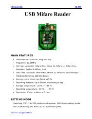
RFID MODULE<br />
<strong>Mifare</strong> <strong>Reader</strong> / Writer<br />
<strong>SL030</strong><br />
<strong>User</strong> <strong>Manual</strong><br />
Version 2.6<br />
Nov 2012<br />
<strong>StrongLink</strong>
<strong>StrongLink</strong> <strong>SL030</strong><br />
http://www.stronglink-rfid.com<br />
CONTENT<br />
1. MAIN FEATURES .................................................................................. 3<br />
2. PINNING INFORMATION ................................................................... 4<br />
3. DEVICE OPERATION ............................................................................ 5<br />
3-1. Clock and Data Transitions: ................................................................... 5<br />
3-2. Start Condition ........................................................................................ 5<br />
3-3. Stop Condition ........................................................................................ 5<br />
3-4. Acknowledge .......................................................................................... 5<br />
3-5. Busy State ............................................................................................... 6<br />
3-6. Device Addressing .................................................................................. 6<br />
3-7. Write Operations..................................................................................... 7<br />
3-8. Read Operations ..................................................................................... 7<br />
4. Command Description .............................................................................. 7<br />
4-1. Format ..................................................................................................... 7<br />
4-2. Command Overview ............................................................................... 8<br />
4-3. Command List ........................................................................................ 9<br />
4-3-1. Select <strong>Mifare</strong> card ................................................................................ 9<br />
4-3-2. Login to a sector ................................................................................... 9<br />
4-3-3. Download Key into <strong>SL030</strong> .................................................................. 9<br />
4-3-4. Login sector via stored key ................................................................ 10<br />
4-3-5. Read a data block ............................................................................... 10<br />
4-3-6. Write a data block .............................................................................. 10<br />
4-3-7. Read a value block ............................................................................. 10<br />
4-3-8. Initialize a value block ....................................................................... 11<br />
4-3-9. Write master key (KeyA) ................................................................... 11<br />
4-3-10. Increment value ................................................................................ 11<br />
4-3-11. Decrement value ............................................................................... 12<br />
4-3-12. Copy value........................................................................................ 12<br />
4-3-13. Read a data page (UltraLight & NTAG203) .................................... 13<br />
4-3-14. Write a data Page (UltraLight & NTAG203) .................................. 13<br />
4-3-15. Power Down ..................................................................................... 13<br />
4-3-16. Get firmware version........................................................................ 13<br />
2
<strong>StrongLink</strong> <strong>SL030</strong><br />
1. MAIN FEATURES<br />
• Tags supported: <strong>Mifare</strong> 1k, <strong>Mifare</strong> 4k, <strong>Mifare</strong> UltraLight and NFC<br />
NTAG203<br />
• Auto-detecting tag<br />
• Built-in antenna<br />
• 0 to 400 KHz bit-wide I 2 C-bus communication<br />
• 2.5 ~ 3.6V VDC operating, I/O pins are 5V tolerant<br />
• Work current less than 40mA @3.3V<br />
• Power down current less than 10uA<br />
• Operating distance: Up to 50mm, depending on tag<br />
• Storage temperature: -40 ºC ~ +85 ºC<br />
• Operating temperature: -25 ºC ~ +70 ºC<br />
• Dimension: 38 × 38 × 3 mm<br />
• The OUT pin at low level indicates tag in detective range, and high<br />
level indicating tag out<br />
http://www.stronglink-rfid.com<br />
3
<strong>StrongLink</strong> <strong>SL030</strong><br />
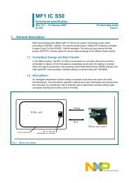
2. PINNING INFORMATION<br />
PIN SYMBOL TYPE DESCRIPTION<br />
1 VDD PWR Power supply, 2.5V to 3.6VDC<br />
2 IN Input Falling edge wake up <strong>SL030</strong> from power down mode<br />
3 SDA Input/Output Serial Data Line<br />
4 SLC Input Serial Clock Line<br />
5 Out Output<br />
Tag detect signal<br />
low level indicating tag in<br />
high level indicating tag out<br />
6 GND PWR Ground<br />
7 NC<br />
8 NC<br />
9 NC<br />
10 NC<br />
http://www.stronglink-rfid.com<br />
4
<strong>StrongLink</strong> <strong>SL030</strong><br />
3. DEVICE OPERATION<br />
3-1. Clock and Data Transitions:<br />
The SDA pin is normally pulled high with an external device. Data on the SDA pin may<br />
change only during SCL low time periods. Data changes during SCL high periods will<br />
indicate a start or stop condition as defined below.<br />
3-2. Start Condition<br />
A high-to-low transition of SDA with SCL high is a start condition which must precede any<br />
other command<br />
3-3. Stop Condition<br />
A low-to-high transition of SDA with SCL high is a stop condition.<br />
3-4. Acknowledge<br />
All addresses and data words are serially transmitted to and from the <strong>SL030</strong> in 8-bit words.<br />
The <strong>SL030</strong> sends a zero to acknowledge that it is not busy, and has received each word.<br />
This happens during the ninth clock cycle.<br />
http://www.stronglink-rfid.com<br />
5
<strong>StrongLink</strong> <strong>SL030</strong><br />
3-5. Busy State<br />
When the <strong>SL030</strong> has received command, then don’t acknowledge <strong>IIC</strong> bus until ends with<br />
the card communication.<br />
3-6. Device Addressing<br />
The <strong>SL030</strong> devices require an 8-bit device address word following a start condition to<br />
enable the chip for a read or write operation.<br />
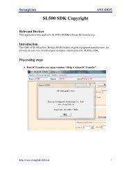
The device address word consists of 7 bits addressing and 1 bit operation select bit.<br />
The first 7 bits are the <strong>SL030</strong> addressing, is 10100xx depend on JP1 and JP2 status as<br />
below table<br />
shorted<br />
http://www.stronglink-rfid.com<br />
JP1 JP2 Address<br />
no no<br />
1010000<br />
( default )<br />
no yes 1010001<br />
yes no 1010010<br />
yes yes 1010011<br />
The eighth bit of the device address is the read/write operation select bit. A read operation<br />
is initiated if this bit is high and a write operation is initiated if this bit is low.<br />
6
<strong>StrongLink</strong> <strong>SL030</strong><br />
3-7. Write Operations<br />
The host device send a command(refer chapter 4) to <strong>SL030</strong> via write operation, then <strong>SL030</strong><br />
will carry out the order that receive. Finished time according to different order<br />
3-8. Read Operations<br />
The host device passes to read the operation gets the order carries out the result<br />
4. COMMAND DESCRIPTION<br />
4-1. FORMAT<br />
Host Write Command to <strong>SL030</strong>:<br />
Address Len Command Data<br />
Address: 1 byte, 0xA0<br />
Len: 1 byte indicating the number of bytes from Command to the end of Data<br />
Command: 1 byte Command code, see Table 3<br />
Data: Variable length depends on the command type<br />
Host Read The Result:<br />
Address Len Command Status Data<br />
Address: 1 byte, 0xA1<br />
Len: 1 byte indicating the number of bytes from Command to the end of Data<br />
Command: 1 byte Command code, see Table 3<br />
Status: 1 byte Command status, see Table 4<br />
Data: Variable length depends on the command type.<br />
http://www.stronglink-rfid.com<br />
7
<strong>StrongLink</strong> <strong>SL030</strong><br />
4-2. Command Overview<br />
Table 3<br />
Command Description<br />
0x01 Select <strong>Mifare</strong> card<br />
0x02 Login to a sector<br />
0x03 Read a data block<br />
0x04 Write a data block<br />
0x05 Read a value block<br />
0x06 Initialize a value block<br />
0x07 Write master key (key A)<br />
0x08 Increment value<br />
0x09 Decrement value<br />
0x0A Copy value<br />
0x10 Read a data page (Ultralight & NATG203)<br />
0x11 Write a data page (Ultralight & NTAG203)<br />
0x12 Download Key<br />
0x13 Login sector via stored Key<br />
0x50 Go to Power Down mode<br />
0xF0 Get firmware version<br />
STATUS OVERVIEW<br />
Table 4<br />
Status Description<br />
0x00 Operation succeed<br />
0x01 No tag<br />
0x02 Login succeed<br />
0x03 Login fail<br />
0x04 Read fail<br />
0x05 Write fail<br />
0x06 Unable to read after write<br />
0x08 Address overflow<br />
0x09 Download Key fail<br />
0x0A Collision occur<br />
0x0C Load key fail<br />
0x0D Not authenticate<br />
0x0E Not a value block<br />
http://www.stronglink-rfid.com<br />
8
<strong>StrongLink</strong> <strong>SL030</strong><br />
4-3. COMMAND LIST<br />
4-3-1. Select <strong>Mifare</strong> card<br />
Host Write:<br />
Len 0x01<br />
Host Read:<br />
Len 0x01 Status UID Type<br />
Status: 0x00: Operation succeed<br />
0x01: No tag<br />
UID: The uniquely serial number of <strong>Mifare</strong> card<br />
Type: 0x01: <strong>Mifare</strong> 1k, 4 byte UID<br />
0x02: <strong>Mifare</strong> 1k, 7 byte UID [1]<br />
0x03: <strong>Mifare</strong> UltraLight or NATG203 [2] , 7 byte UID<br />
0x04: <strong>Mifare</strong> 4k, 4 byte UID<br />
0x05: <strong>Mifare</strong> 4k, 7 byte UID [1]<br />
0x06: <strong>Mifare</strong> DesFire, 7 byte UID<br />
0x0A: Other<br />
4-3-2. Login to a sector<br />
Host Write:<br />
Len 0x02 Sector Type Key<br />
Sector: Sector need to login, 0x00 – 0x27<br />
Type: Key type (0xAA: authenticate with KeyA, 0xBB: authenticate with KeyB)<br />
Key: Authenticate key, 6 bytes<br />
Host Read:<br />
Len 0x02 Status<br />
Status: 0x02: Login succeed<br />
0x01: No tag<br />
0x03: Login fail<br />
0x08: Address overflow<br />
4-3-3. Download Key into <strong>SL030</strong><br />
Host Write:<br />
Len 0x12 Sector Type Key<br />
Sector: 0x00 – 0x27<br />
Type: Key type (0xAA: KeyA, 0xBB: KeyB)<br />
Key: 6 bytes, stored into <strong>SL030</strong><br />
Host Read:<br />
Len 0x12 Status<br />
Status: 0x00: Operation succeed<br />
0x08: Address overflow<br />
0x09: Download fail<br />
http://www.stronglink-rfid.com<br />
9
<strong>StrongLink</strong> <strong>SL030</strong><br />
4-3-4. Login sector via stored key<br />
Host Write:<br />
Len 0x13 Sector Type<br />
Sector: Sector need to login, 0x00 – 0x27<br />
Type: Key type (0xAA: KeyA, 0xBB: KeyB)<br />
Host Read:<br />
Len 0x13 Status<br />
Status: 0x02: Login succeed<br />
0x03: Login fail<br />
0x08: Address overflow<br />
4-3-5. Read a data block<br />
Host Write:<br />
Len 0x03 Block<br />
Block: The absolute address of block to be read, 1 byte<br />
Host Read:<br />
Len 0x03 Status Data<br />
Status: 0x00: Operation succeed<br />
0x01: No tag<br />
0x04: Read fail<br />
0x0D: Not authenticate<br />
Data: Block data returned if operation succeeds, 16 bytes.<br />
4-3-6. Write a data block<br />
Host Write:<br />
Len 0x04 Block Data<br />
Block: The absolute address of block to be written, 1 byte.<br />
Data: The data to write, 16 bytes.<br />
Host Read:<br />
Len 0x04 Status Data<br />
Status: 0x00: Operation succeed<br />
0x01: No tag<br />
0x05: Write fail<br />
0x06: Unable to read after write<br />
0x0D: Not authenticate<br />
Data: Block data written if operation succeeds, 16 bytes.<br />
4-3-7. Read a value block<br />
Host Write:<br />
Len 0x05 Block<br />
Block: The absolute address of block to be read, 1 byte.<br />
Host Read:<br />
Len 0x05 Status Value<br />
http://www.stronglink-rfid.com<br />
10
<strong>StrongLink</strong> <strong>SL030</strong><br />
Status: 0x00: Operation succeed<br />
0x01: No tag<br />
0x04: Read fail<br />
0x0D: Not authenticate<br />
0x0E: Not a value block<br />
Value: Value returned if the operation succeeds, 4 bytes.<br />
4-3-8. Initialize a value block<br />
Host Write:<br />
Len 0x06 Block Value<br />
Block: The absolute address of block to be initialized, 1 byte.<br />
Value: The value to be written, 4 bytes.<br />
Host Read:<br />
Len 0x06 Status Value<br />
Status: 0x00: Operation succeed<br />
0x01: No tag<br />
0x05: Write fail<br />
0x06: Unable to read after write<br />
0x0D: Not authenticate<br />
Value: Value written if the operation succeeds, 4 bytes.<br />
4-3-9. Write master key (KeyA)<br />
Host Write:<br />
Len 0x07 Sector Key<br />
Sector: The sector number to be written, 0x00 – 0x27.<br />
Key: Authentication key, 6 bytes<br />
Host Read:<br />
Len 0x07 Status Key<br />
Status: 0x00: Operation succeed<br />
0x01: No tag<br />
0x05: Write fail<br />
0x08: Address overflow<br />
0x0D: Not authenticate<br />
Key: Authentication key written if the operation succeeds, 6 bytes.<br />
Attention: Be sure KeyB is readable, otherwise KeyB will be change to 000000000000<br />
after this command.<br />
4-3-10. Increment value<br />
Host Write:<br />
Len 0x08 Block Value<br />
Block: The absolute address of block to be increased, 1 byte.<br />
Value: The value to be increased by, 4 bytes.<br />
Host Read:<br />
http://www.stronglink-rfid.com<br />
11
<strong>StrongLink</strong> <strong>SL030</strong><br />
Len 0x08 Status Value<br />
Status: 0x00: Operation succeed<br />
0x01: No tag<br />
0x05: Write fail<br />
0x06: Unable to read after write<br />
0x0D: Not authenticate<br />
0x0E: Not a value block<br />
Value: The value after increment if the operation succeeds, 4 bytes<br />
4-3-11. Decrement value<br />
Host Write:<br />
Len 0x09 Block Value<br />
Block: The absolute address of block to be decreased, 1 byte<br />
Value: The value to be decreased by, 4 bytes<br />
Host Read:<br />
Len 0x09 Status Value<br />
Status: 0x00: Operation succeed<br />
0x01: No tag<br />
0x05: Write fail<br />
0x06: Unable to read after write<br />
0x0D: Not authenticate<br />
0x0E: Not a value block<br />
Value: The value after decrement if the operation succeeds, 4 bytes<br />
4-3-12. Copy value<br />
Host Write:<br />
Len 0x0A Source Destination<br />
Source: The source block copy from, 1 byte<br />
Destination: The destination copy to, 1 byte<br />
The source and destination must in the same sector<br />
Host Read:<br />
Len 0x0A Status Value<br />
Status: 0x00: Operation succeed<br />
0x01: No tag<br />
0x05: Write fail<br />
0x06: Unable to read after write<br />
0x0D: Not authenticate<br />
0x0E: Not a value block (Source)<br />
Value: The value after copy if the operation succeeds, 4 bytes<br />
http://www.stronglink-rfid.com<br />
12
<strong>StrongLink</strong> <strong>SL030</strong><br />
4-3-13. Read a data page (UltraLight & NTAG203)<br />
Host Write:<br />
Len 0x10 Page<br />
Page: The page number to be read, 1 byte<br />
Host Read:<br />
Len 0x10 Status Data<br />
Status: 0x00: Operation succeed<br />
0x01: No tag<br />
0x04: Read fail<br />
0x08: Address overflow<br />
Data: Block data returned if operation succeeds, 4 bytes.<br />
4-3-14. Write a data Page (UltraLight & NTAG203)<br />
Host Write:<br />
Len 0x11 Page Data<br />
Page: The page number to be written, 1 byte.<br />
Data: The data to write, 4 bytes.<br />
Host Read:<br />
Len 0x11 Status Data<br />
Status: 0x00: Operation succeed<br />
0x01: No tag<br />
0x05: Write fail<br />
0x06: Unable to read after write<br />
0x08: Address overflow<br />
0xF0: Checksum error<br />
Data: page data written if operation succeeds, 4 bytes.<br />
4-3-15. Power Down<br />
Host Write:<br />
Len 0x50<br />
Host Read:<br />
No response until falling edge at PIN2 or repower<br />
4-3-16. Get firmware version<br />
Host Write:<br />
Len 0xF0<br />
Host Read: [3]<br />
Len 0xF0 Status Data<br />
Status: 0x00: Operation succeed<br />
Data: firmware version.<br />
http://www.stronglink-rfid.com<br />
13
<strong>StrongLink</strong> <strong>SL030</strong><br />
Remark<br />
[1]<br />
In order to support 7 byte UID <strong>Mifare</strong> class, the firmware of <strong>SL030</strong> has been<br />
updated to Ver3.2 in Mar 2011.<br />
And older firmware version (such as Ver1.0, 2.0, 2.2, etc) only supports 4 byte UID.<br />
Please refer to NXP Customer Letter UID for detailed information of 4 byte & 7 byte<br />
UID of <strong>Mifare</strong> products.<br />
[2] To support NATG203, the firmware of <strong>SL030</strong> has been updated to Ver3.9 in May<br />
2012. The older firmware version only supports reading/writing data page address less<br />
than 16.<br />
[3] One sample of <strong>SL030</strong> response<br />
Len Command Status Data<br />
(Firmware version)<br />
HEX 0B F0 00 53 4C 30 33 30 2D 33 2E 32<br />
ASCII “<strong>SL030</strong>-3.2”<br />
http://www.stronglink-rfid.com<br />
14