
You also want an ePaper? Increase the reach of your titles
YUMPU automatically turns print PDFs into web optimized ePapers that Google loves.
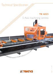
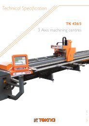
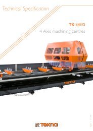
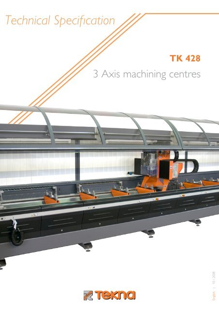
Technical Specification<strong>TK</strong> <strong>428</strong>3 Axis machining centresEnglish | 10 / 2008
3 Axis machining centres<strong>TK</strong> <strong>428</strong>
3 Axis machining centres<strong>TK</strong> <strong>428</strong>TEKNA was established in 1964 to produce efficient aluminum machining systems.The major role played by this material in the building industry has led TEKNA to develop, over the years, a vast range ofproducts for manufacturers of window/door frames, curtain walls and coatings.The increasing use of aluminum components in the automotive and transport industries as well as in the consumer industriesand in other industrial branches has encouraged the search for new solutions: TEKNA has seized this opportunity andinvested into it in order to meet the new demands of the market.The experience gained in the window/door frames industry and the know-how accumulated in the field of machinery have allowedTEKNA to expand its product range, including 3-,4- and 5-axis machining centers for the machining of panels and profiles.Over the past 15 years we have designed several models that have been customized according to the machining needs ofour customers. TEKNA has developed different profile clamping systems for the machining processes, the movement controlsand the suction systems of chips and dust.Nowadays our company receives and answers to feasibility study requests every week, for this reason we can state thatTEKNA is extremely qualified to provide effective responses to the most diverse problems.Thanks to its vast experience, TEKNA can offer effective systems to be used in the manufacturing of window/door frames,curtain walls, industrial doors, garage door and panels, accessories for commercial vehicles, components for trains andunderground trains, parts for the automotive industry, for telecommunication booths and many other applications.
3 Axis machining centres<strong>TK</strong> <strong>428</strong>3-axis CNC vertical machining center.Structure robustness and high stability of all components of this machining center allow the <strong>TK</strong> <strong>428</strong> model to be used not onlyto perform machining operations on light alloys and similar materials but also on materials that require higher performances (i.e.steel, iron, etc.). The peculiarities of the machine assure an excellent superficial finishing and a better machining accuracy.This machining center is designed for drilling and conventional milling processes and also for copy-milling operations onaluminum extruded profiles and other materials, including steel profiles up to 10 mm thick, steel reinforced PVC, and variousother plastics or wood.Standard versions are available in 3 machining lengths: 3500, 6500 and 8000 mm. Upon request the machining center can bemanufactured in different lengths in order to meet the special needs of each customer.Over the years TEKNA has produced various versions of the <strong>TK</strong> <strong>428</strong> model customizing it in order to machine compositepanels, sectional panels, etc.; TEKNA has designed several systems for clamping, for automatic loading/unloading processes,for the moving of profiles as well as dust suction systems.
3 Axis machining centres<strong>TK</strong> <strong>428</strong>
3 Axis machining centres<strong>TK</strong> <strong>428</strong>MachinabilityTool projection L = 50 mm40 4040 40 4040130130130130220220720770800298 298363 363378 3783500 - 6500 - 80002750 mm (L = 6500)3500 mm (L = 8000)2750 mm (L = 6500)3500 mm (L = 8000)
3 Axis machining centres<strong>TK</strong> <strong>428</strong>Technical featuresMachinabilityAxis X3500 mm6500 mm8000 mmAxis Y800 mmAxis Z220 mmMax displacement speedAxis X80 m/1’Axis Y30 m/1’Axis Z30 m/1’Control of axesAxis XBrushless motor, truck on ball linear slideways, double precision rackAxis Y - ZBrushless motors, ball linear slideways and ball screwsElectric-spindleCone attachment ISO 30Max power (S1 service)7,5 kWMax torque (S1 service)11,9 NmMax rotation speed24.000 rpmCooling systemElectric cooling fanTool storeN° tools 9 tools + 9 optionalTool change time 5’’ - 10’’AccuracyRepetition on linear positioning+/- 0,1 mm
3 Axis machining centres<strong>TK</strong> <strong>428</strong>Machining limits with electric-spindle on 0°Drilling from solidAluminuim AL99 Ø 20Steel FE370 D FF Ø 14Rectilinear milling (maximum thickness)Aluminuim AL99 20Steel FE370 D FF 10Tapping from solidAluminuim AL99M 12 (with 6 kW electric spindle)Steel FE370 D FFM 12 (with 6 kW electric spindle)Flowdrill: max screw threadsCutting tap M 10Rolling tap M 8Notes: The drilling and milling tools are the hard metal ones. Wider diameters can be obtained with the axes interpolation. Larger tappings can be obtained with the helical interpolation. The reported maximum screw thread sizes obtained with flow drill are valid for both aluminium and steel.
3 Axis machining centres<strong>TK</strong> <strong>428</strong>Basic machine dimensions + full protectionBCAG1DHG2EFBasic machine (mm) Conveyor belt Full protectionL=3500L=6500L=8000A B C D E F G1 G2 H5120841098201900 400 2000 2000 2700 300 200 2500 maxWeight (Kg)L=3500 L=6500 L=8000Basic machine 2700 3800 4700Full protection 270 430 550Conveyor belt 140 175 220
10 3 Axis machining centres<strong>TK</strong> <strong>428</strong>Construction FeaturesThe structure of the machining center features an electrically welded steel bed frame where linear slideways with recirculatingballs are mounted as well as precision racks that allow the movement of the milling head along the X axis. Thanks to the bedframe design it is possible to load bars longer than the machine working length.The milling head is designed to provide a high Y and Z axis stiffness in order to minimize the vibrations that would compromisethe machine precision and would negatively affect the quality of the machining process.It is made up by a portal structure in aluminum casting that is composed of two lateral supporting elements and a topcrosspiece. On this crosspiece linear slideways and the ball screws with recirculating balls are mounted for Y and Z axis.The back side of the machine is equipped with a chute made up of metal panels mounted along the whole length of this side,whose aim is to push the chips produced during the machining towards the conveyor belt.The back and front sides of the machine are equipped with panels that can be removed to easily perform maintenanceoperations.
3 Axis machining centres11<strong>TK</strong> <strong>428</strong>Linear slideways with recirculating ballsLinear slideways with recirculating balls facilitate the movement along the machining axis of the milling head and of othercomponents of the machining centre. The system comprises driving ground bars and carriages equipped with scrapers andweather strips that protects from chips and dust the two internal groups of recirculating balls.These guides can stand similar traction and compression loads while keeping a low friction coefficient, a high resistance tovibrations and an optimal smoothness.These characteristics improve the high-quality performance of machining centers: an efficient movement of the machinecomponents that enables a high-precision positioning.
123 Axis machining centres<strong>TK</strong> <strong>428</strong>Electric-spindleThe machining center has an electric-spindle which is equipped with an automatic tool change system with an electric coolingfan for maintaining a constant temperature and preventing the machine from overheating.The fan operation is independent of the electric-spindle rotation, therefore the fan can work without interruption (even whenthe spindle is not rotating) thus providing an improved system cooling.The max power is 7,5 kW in S1 operation mode, with a max rotation speed of 24000 rpm.8.68.17.576.35.55.24.5kWrpm x 10006121824S 6 60%S 1 continuous
3 Axis machining centres13<strong>TK</strong> <strong>428</strong>Minimal LubricationMinimal lubrication system with micro-drop technology that optimizes the cooling liquid consumption during the machining.In order to guarantee a suitable cooling of the tool, this system allows also to distinctly reduce the quantity of the used product.The airflow passes through the nozzles installed at the end of the electric spindle and reaches the contact area between thetool and the piece to be machined; the provided air is under pressure and mixed with a small quantity of cooling oil.Thanks to this system it is possible to limit the volume of liquid remaining on the machined piece, thus obtaining a cleanermachining area.
14 3 Axis machining centres<strong>TK</strong> <strong>428</strong>Pneumatic clampsPneumatic clamping system for the clamping of traditional profiles. The longitudinal and transversal positioning is achievedthrough manual adjustments.Fixed tool magazineFixed tool magazine that is installed on the left end of the machining center and can hold up to 9 tools. It is possible to insertan additional tool magazine or to provide this model with a removable enclosure that protects tools from chips and dustsformed during the machining process (optional), according to the customer’s needs.
3 Axis machining centres15<strong>TK</strong> <strong>428</strong>TwinThe <strong>TK</strong> <strong>428</strong> model features the TWIN operation mode that enables the operator to divide the machine into two well-distinctmachining areas: the operator can access one of the two areas for changing the workpiece, while in the second area themachine keeps working; in this way it is possible to perform different machining processes in the two distinct areas.An intermediate area is delimited by two safety light barriers in order to assure the safety of the operator when the machineis used in this mode.This system increases and optimizes the productivity because it eliminates the idle times caused by the machine downtimeand it gives the possibility to perform different machining processes in the two separated areas.The TWIN system can be mounted on machines with machinable lengths of 6500 and 8000 mm.Safety protectionThe <strong>TK</strong> <strong>428</strong> model is equipped with a safety light barrier system that prevents the operator from accessing dangerous zoneswhen the machine is working: the operator is allowed to access the machine only when safety conditions are met.All moving parts are suitably protected through an enclosure mounted on three sides (back and lateral) of the machine to preventany accidental contact; it is made up of insulating and sound-absorbing panels that can be removed for maintenance operations.
16 3 Axis machining centres<strong>TK</strong> <strong>428</strong>Panel machiningTEKNA has developed several solutions for the machining of panels on the <strong>TK</strong> <strong>428</strong> machining center; for the panel clampingwe designed systems that are composed of vacuum tables that allow composite panels and plates to be held by vacuum aswell as systems completed with suction cups for the clamping of sectional panels.In order to facilitate the workpiece movement, TEKNA has developed machining tables that are provided with rollers; by meansof a translation system equipped with suction cups the panel is clamped and automatically moved along the machining table.Among other solutions offered by TEKNA to meet each customer’s need, we produce also dust suction devices and loading/unloading roller tables.
Optional3 Axis machining centres<strong>TK</strong> <strong>428</strong>17Full automatic protectionThe scope of the full enclosure is to protect the operator against accidental contacts with moving components of the machineand the produced chips and to reduce the noise level.The enclosure is installed on three perimeter sides and on top of the machine, it is made up of insulating and sound-absorbingpanels that can be removed for maintenance operations. It is provided with front shields made up of two frames of extrudedaluminum with transparent shields. In the TWIN mode, it is possible to independently open and close each half of the frontenclosure, by controlling them from the CNC system.
18 3 Axis machining centres Optional<strong>TK</strong> <strong>428</strong>Pneumatic two-way clampsIt is possible to use both one- and two-way clamps: Using a two-way clamp you can simultaneously machine 2 profiles withdifferent dimensions and machining processes.
Optional3 Axis machining centres<strong>TK</strong> <strong>428</strong>19Motor-driven tool magazineThis magazine is mounted on machine with machinable lengths of 6500 and 8000 mm.It is installed in the central area of the machine and it electrically moves on both sides of the TWIN area, reducing the toolchange interval. It holds up to 14 tools and 2 aggregate heads.Mobile tool magazine9 position tool magazine designed to reduce tool change time. The tool magazine is pulled by the carriage along the X axisin a programmable position.
20 3 Axis machining centres Optional<strong>TK</strong> <strong>428</strong>Aggregate headsRight angle gearbox that can hold one or two tools and that is equipped with a cone (ISO 30) compatible with the toolattachment of the electric spindle.The aggregate head is used to perform: Machining processes where the electric spindle axis is not parallel to the Z axis Machining processes that use a shear blade located perpendicular to the machining table Head machiningMotor-driven conveyor beltIt collects chips and conveys them to the far right end of the table, unloading them in a container, if any.
Optional3 Axis machining centres<strong>TK</strong> <strong>428</strong>21Auxiliary container for cooling liquid (30 liter)It reduces the duration of the machine downtime necessary to feed the standard tank; it is the ideal solution for continuousworking cycles.Laser detection kitIf more profiles are located on the machine length without a precise position, this kit detects them and determines the zeropoint for the program.
22 3 Axis machining centres Optional<strong>TK</strong> <strong>428</strong>3D ProbeContact probe that is used to accurately inspect the workpieces with complex geometric forms. This device improves theproductivity thanks to the fast and accurate measurement of the components.Barcode readerThis device reads the labels applied on profiles and allows the system to automatically load the machining program and thetransfer of some parameters of use. The reader is also available in “wireless” release.
Optional3 Axis machining centres<strong>TK</strong> <strong>428</strong>23Anticollision light system with LED barsThis system allows to analyze any machining program and, through light indicators, to show the areas where clamps can bepositioned in order to avoid collisions with the spindle.
24 3 Axis machining centres Optional<strong>TK</strong> <strong>428</strong>Remote controlled electronic wheelIt moves the axis and performs milling operations activated by manual commands, allowing the operator to walk along themachine. Thanks to the electronic wheel it is also possible to start and run the machining program without going back to thecommand console.Voltage stabilizerIt stabilizes the machine voltage supply, even if some voltage losses occur.Uninterruptible power supply (UPS)The UPS is a device which maintains a continuous supply of electric power when utility power is not available.In case of a blackout, while the machine enters emergency mode, the CNC does not stop (because it is powered by the UPS)thus allowing the operator to save manually or with an automatic routine the already performed job.
Software3 Axis machining centres<strong>TK</strong> <strong>428</strong>25HardwareThe CN6 hardware is made up by two processors: A processor controls the CN6 and the other controls the functionsof a common PC; thanks to this system you can use the function of the common PC even while the machining center isworking.It includes:CPU PENTIUM cardKeyboard, mouse, LCD 17’’ color screenEthernet card for the network connectionUSB and parallel portsAxis and spindle speed control cardsHard Disk with minimum capacity of 40 GbModem for the direct connection via Internet
26 3 Axis machining centres Software<strong>TK</strong> <strong>428</strong>CN6 Numerical ControlThe Numerical Control basic software controls all functionalities of the machining center through an interface based onwindows that includes: User graphic interface (HMI, Human Machine Interface) that displays all variables of the center (for example spindleposition, tool rotation and feed, etc.) and from which it is possible to activate some auxiliary devices (such as lubricationsystem, chips belt, etc.) User table that combines each tool with one or more performance such as rotation speed, penetration speed or millingspeed A series of table with all configuring parameters of the center
Software3 Axis machining centres<strong>TK</strong> <strong>428</strong>27CN6The CN6 license includes:Numerical Control management softwareISO Language EditorSLW (Self-Learning software)Formulas SoftwareSoftware for remote connectionISO language editorFor numeric-control machines the international programming language ISO is used. With this language you can createprograms to perform every kind of machining, with linear or interpolated paths, variable speeds, tapping, parameter use etc.and for managing all functionalities of the machining center.
28 3 Axis machining centres Software<strong>TK</strong> <strong>428</strong>SLW Self-learningTekna owns the SLW (Self Learning for Windows): a language of superior level then the ISO language . Thanks to a defaultnumber of functions (macros) that can be selected from a graphic menu, it is possible to easily create machining programs.Coordinates (values in X, Y and Z) must be assigned to each selected macro and other machining programs; each macro canbe activated both as ISO and SLW program. During the selection and the setting of the chosen macros, these are translatedin ISO language, thus creating a file that can be saved as machining program.The macro library generated by Tekna includes a large number of machining; using this library an advanced user can createseveral machining programs very easily.It is also possible to create and add to the macro library other specific macros customized by the client.The Self-Learning SLW is very user-friendly: after a two-hour training even a beginner user can use the machine.
Software3 Axis machining centres<strong>TK</strong> <strong>428</strong>29FormulasThis is a software that can be used with Self-Learning SLW. You can use it to define formulas based on the default variables(i.e. the profile length) and then use them in the Self-Learning macros. This function is very useful when you have to performsame machining processes on profiles of various lengths. For example, the position in X of a hole can be set as L/2-50, whereL must be correctly assigned (by inserting it manually, via a bar code reader o with a kind of automatism).Remote connectionThis functionality allows to directly update the CN6, Maintenance and Technical Support on the machine, remotely via Internetusing a telephone line (modem) or via a LAN (Ethernet card).
30 3 Axis machining centres Optional software<strong>TK</strong> <strong>428</strong>NC ToolNC Tool is a 2D CAD/CAM software based on AutoCAD software: With the appropriate setting of the parameters, thissoftware creates ISO programs that are CN6-compatible.The main functionalities of the NC Tool software are:Drawing file importEasy setting of the desired machiningAutomatic creation of ISO programs that are CN6-compatibleAny changes to geometrical scales and to the dimensions of an existing drawing are automatically converted in a new updatedISO program.NC Tool can import/export .dxf and .dwg files, moreover it allows text editing and the subsequent generation of ISO codes.
Optional software3 Axis machining centres<strong>TK</strong> <strong>428</strong>31<strong>TK</strong> camSoftware package that allows the creation of ISO programs using a 3D graphic programming.With <strong>TK</strong> CAM it is possible to assign machining operation regardless of machine models and tool series and view a simulationof the running program in a 3D representation. In <strong>TK</strong> CAM it is possible to optimize tools and clamps, it provides an anticollisionfunction and the automatic generation of ISO codes for the program. In the <strong>TK</strong> CAM it is possible to import specific.dxf/.dwg drawings and to assign the corresponding machining operations. In addition, details of the described machiningprocesses can be imported in <strong>TK</strong> CAM in a generic .xlm format: This functionality allows the interaction with the managementprograms commonly used in the window and door frame manufacturing industry.
Technical SpecificationDATA AND GRAPHICS ON THIS CATALOGUE ARE PROVIDED MERELY FOR INFORMATION PURPOSES. TEKNA RESERVES THE RIGHT TO CHANGE THE CATALOGUE WITHOUT PREVIOUS NOTICE, FOR TECHNICAL ORCOMMERCIAL PURPOSES.<strong>TK</strong> <strong>428</strong>3 Axis machining centresBranchesTeknacentroTekna Nordest<strong>TK</strong> Maquinaria<strong>TK</strong> Portuguesa<strong>TK</strong> PortoTekna DeutschlandTekna UsaSouth AmericaChinaVia Monte Bisbino, 5620021 Baranzate (Milan) • ItalyTel. +39 02356961Fax +39 023562293tekna@tekna.itwww.tekna.itEnglish | 10 / 2008