Formation of atomic point contacts and molecular junctions with a ...
Formation of atomic point contacts and molecular junctions with a ...
Formation of atomic point contacts and molecular junctions with a ...

You also want an ePaper? Increase the reach of your titles
YUMPU automatically turns print PDFs into web optimized ePapers that Google loves.
<strong>Formation</strong> <strong>of</strong> <strong>atomic</strong> <strong>point</strong> <strong>contacts</strong> <strong>and</strong> <strong>molecular</strong><strong>junctions</strong> <strong>with</strong> a combined mechanical breakjunction <strong>and</strong> electrodeposition methodX.L. Li, S.Z. Hua, H.D. Chopra <strong>and</strong> N.J. TaoAbstract: A method to create <strong>atomic</strong> <strong>point</strong> <strong>contacts</strong> <strong>and</strong> <strong>molecular</strong> <strong>junctions</strong> by combiningmechanically controlled break junction <strong>and</strong> electrochemical deposition/etching techniques isdescribed. This approach provides both stability <strong>and</strong> flexibility, <strong>and</strong> is suitable for studying electrontransport properties <strong>of</strong> single molecule <strong>junctions</strong> or <strong>atomic</strong> <strong>point</strong> <strong>contacts</strong> in aqueous solutions <strong>and</strong>under potential control. Using the approach, the electron transport properties <strong>of</strong> 4,4 0 -bipyridine as afunction <strong>of</strong> electrochemical gate <strong>and</strong> Ni <strong>point</strong> <strong>contacts</strong> have been studied.1 IntroductionIn order to determine the electron transport properties <strong>of</strong> asingle molecule, one must first connect the molecule to atleast two external electrodes. One way to achieve thisrequirement is to fabricate a pair <strong>of</strong> facing electrodes on asolid substrate <strong>and</strong> then bridge the electrodes <strong>with</strong> the moleculeterminated <strong>with</strong> proper anchoring groups that can bindto the electrodes. A key task <strong>of</strong> this method is to fabricateelectrodes separated <strong>with</strong> a <strong>molecular</strong> scale gap, whichhas been a difficult task. This is because most moleculesare a few nanometres or less, <strong>and</strong> the fabrication <strong>of</strong> such asmall gap between electrodes is beyond the reach <strong>of</strong> conventionalmicro- <strong>and</strong> nan<strong>of</strong>abrication facilities [1–11].A closely related system is <strong>atomic</strong> <strong>point</strong> <strong>contacts</strong> in whichtwo electrodes are connected by a single or a smallnumber <strong>of</strong> metal atoms [12–16]. For many metals, suchas Au, the conductance <strong>of</strong> an <strong>atomic</strong> <strong>point</strong> contact isquantised, approximately given by an integer multiple <strong>of</strong>G 0 ¼ 2e 2 /h ¼ 77.4 mS. Such a system is also interestingfor its rich magneto-transport properties [17–19].One method that has been used to create a <strong>molecular</strong>junction <strong>and</strong> <strong>atomic</strong> <strong>point</strong> contact is mechanically controllablebreak junction (MCBJ) [20–22]. The basic principle <strong>of</strong>MCBJ is to break a nanobridge between two electrodesfixed on a substrate fabricated <strong>with</strong> techniques, such as electronbeam lithography. The breakdown process is controlledby bending the substrate <strong>with</strong> a mechanical actuator (e.g.piezoelectric transducer (PZT) <strong>and</strong> a stepping motor)(Fig. 1). Bending the substrate elongates the narrowbridge, which reduces the diameter <strong>of</strong> the thinnest portion<strong>of</strong> the bridge. When the thinnest portion is decreased tothe <strong>atomic</strong> scale, an <strong>atomic</strong> <strong>point</strong> contact is eventuallyformed. If one chooses to further bend the substrate, the# The Institution <strong>of</strong> Engineering <strong>and</strong> Technology 2006Micro & Nano Letters online no. 20065049doi:10.1049/mnl:20065049Paper first received 8th September 2006X.L. Li <strong>and</strong> N.J. Tao are <strong>with</strong> the Department <strong>of</strong> Electrical Engineering, ArizonaState University, Tempe, AZ 85287, USAS.Z. Hua <strong>and</strong> H.D. Chopra are <strong>with</strong> the Materials Program, Mechanical <strong>and</strong>Aerospace Engineering Department, State University <strong>of</strong> New York at Buffalo,Buffalo, NY 14260, USAE-mail: xiulan@asu.edubridge breaks <strong>and</strong> results in a gap between the two facingelectrodes. By connecting the gap <strong>with</strong> a molecule <strong>of</strong> interest,a <strong>molecular</strong> junction is formed. An important advantage<strong>of</strong> MCBJ is that the formation <strong>of</strong> an <strong>atomic</strong> <strong>point</strong> contact, ora <strong>molecular</strong> scale gap can be continuously adjusted.However, the mechanical actuation makes it complicated<strong>and</strong> difficult for many potential device applications <strong>and</strong> itis also limited to <strong>contacts</strong> between the same metal.Another technique to fabricate <strong>atomic</strong> <strong>point</strong> <strong>contacts</strong><strong>and</strong> <strong>molecular</strong> <strong>junctions</strong> is the electrochemical method [1, 2,4, 23–25]. One strategy is to electrochemically etch thenarrow portion <strong>of</strong> a metal wire fixed on a solid substrateuntil it decreases to the <strong>atomic</strong> scale to form an <strong>atomic</strong><strong>point</strong> contact, or a <strong>molecular</strong> scale gap for <strong>molecular</strong> <strong>junctions</strong>[1]. An alternative approach is to start <strong>with</strong> a pair <strong>of</strong> electrodesseparated initially <strong>with</strong> a large gap, <strong>and</strong> then electrochemicallydeposit atoms onto the electrodes to decrease the gap to the<strong>molecular</strong> scale, or all the way, until an <strong>atomic</strong> <strong>point</strong>contact is created [1, 2, 4, 23]. Since electrochemicaletching (deposition) is reversible, the electrochemical fabricationmethods allow one to control the fabrication processuntil a desired gap or contact is reached. In comparison tothe mechanical method, the electrochemical method doesnot require mechanical actuation, can fabricate the electrodesor <strong>contacts</strong> <strong>with</strong> different metals [26], <strong>and</strong> is amenable todevice applications.Combination <strong>of</strong> MCBJ <strong>and</strong> electromigration to study thesingle-molecule transistor <strong>with</strong> solid gate was demonstratedby Ralph <strong>and</strong> co-workers [27]. We report here a combinedmechanical <strong>and</strong> electrochemical method to fabricate<strong>atomic</strong> <strong>point</strong> <strong>contacts</strong> <strong>and</strong> <strong>molecular</strong> <strong>junctions</strong> in aqueoussolutions. The technique combines the advantages <strong>of</strong> theelectrochemical method along <strong>with</strong> the ability to makeadjustable gaps afforded by the mechanical method. Theaqueous environment is required for studying biologicallyrelevant molecules, <strong>molecular</strong> binding process <strong>and</strong> is convenientfor one to introduce sample molecules into themeasurement. In addition, it allows one to control the electrontransport processes through the <strong>atomic</strong> <strong>point</strong> <strong>contacts</strong> or<strong>molecular</strong> <strong>junctions</strong> using an electrochemical gate. Usingthis method, we have measured the conductance <strong>of</strong>4,4 0 -bipyridine <strong>and</strong> studied the electrochemical gate effecton the conductance <strong>of</strong> the molecule. We have als<strong>of</strong>abricated <strong>and</strong> studied charge transport across Ni <strong>atomic</strong><strong>point</strong> <strong>contacts</strong>.Micro & Nano Letters, Volume 1, Issue 2 83
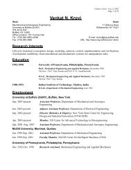
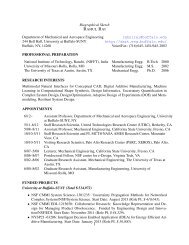
Fig. 1 Schematic drawing <strong>of</strong> a MCBJ setupAu wire <strong>with</strong> nanobridge in the middle is fixed on a substrateThe device is mounted by a three-<strong>point</strong> setupBy bending up the substrate <strong>with</strong> a mechanical actuator (e.g. piezoelectrictransducer <strong>and</strong> a stepping motor), the nanobridge is elongated2 Experimental method <strong>and</strong> resultsWe first fabricated a pair <strong>of</strong> Au electrodes separated <strong>with</strong>1 mm gap on an Si substrate using photolithography. Toreduce ionic leakage current, the Au electrodes werecovered <strong>with</strong> Si 3 N 4 insulating layer except for a smallwindow to expose the gap. We then etched a trench in theSi underneath the Au electrodes to suspend the electrodes.The last step was to reduce the separation <strong>of</strong> the two suspendedelectrodes to a <strong>molecular</strong> gap or to form an <strong>atomic</strong><strong>point</strong> contact by electrochemically depositing Au onto theelectrodes. A mechanical actuation in an MCBJ configurationallows one to further adjust the gap or contact between theelectrodes. We provide more fabrication details <strong>and</strong> discussexperimental results subsequently.2.1 Fabrication <strong>of</strong> the deviceWe used a 360-mm thick Si (1 0 0) wafer (7–13 V cmresistivity) covered <strong>with</strong> a 50 nm thermal SiO 2 insulationlayer. We then patterned the Si substrate <strong>with</strong> an array <strong>of</strong>Au electrode pairs using st<strong>and</strong>ard photolithography tools.The separation between the two electrodes in each pairwas 1 mm. The Au electrodes were thermally evaporated<strong>with</strong> a thickness <strong>of</strong> 60–100 nm on top <strong>of</strong> 8-nm Cradhesion layer. Thicker Au electrodes were not attemptedto avoid hard lift-<strong>of</strong>f. A 400-nm thick Si 3 N 4 layer wasdeposited by chemical vapour deposition (CVD) on theentire wafer except for a 10-mm wide strip that exposesthe gap regions <strong>of</strong> all the electrode pairs. The Si 3 N 4 layerserved as an insulation layer to minimise leakage currentdue to ionic conduction which is important for carryingout electrical measurement in electrolytes. The leakagecurrent was typically a few pA, but it increased afterwet-etching Si 3 N 4 , SiO 2 <strong>and</strong> Si. The Si 3 N 4 also functionedas a mask needed to etch the 10-mm wide strip into a trench.This was carried out by first removing the Si 3 N 4 <strong>and</strong> SiO 2using 20:1 buffered oxide etchant (BOE). The etch ratewas calibrated on Si wafer <strong>with</strong> thermal SiO 2 or CVDSi 3 N 4 in advance. It was followed by etching away theexposed Si in the strip in 0.44 g/ml KOH. This wetetching was anisotropic <strong>and</strong> it created a triangular trenchin the Si substrate (Fig. 2a). We covered the backside <strong>of</strong>the wafer by another layer <strong>of</strong> 400 nm CVD Si 3 N 4 beforewet etching Si, in order to prevent the backside frometching during the last etching process. Before electrochemicaldeposition <strong>of</strong> Au in the next step, we usedoxygen plasma to remove the organic contaminationduring the process, followed by rinsing <strong>with</strong> acetone,ethanol, <strong>and</strong> 18-MV pure water for 5 min each.84Fig. 2 SEM images <strong>of</strong> two pairs <strong>of</strong> Au electrodesa Without Au deposition, Au electrodes are separated <strong>with</strong> 1 mm gapb After Au deposition, an Au nanojunction is formed. Note that theL-shape electrode in the upper left <strong>of</strong> a is a marker for alignmentduring the micr<strong>of</strong>abrication processThe inset is a typical current plot during electrodeposition processshowing that a rather stable <strong>molecular</strong> gap can be obtained by controllingthe potentialThe bias was 0.01 V during the electrodepositionThe two Au electrodes in a pair were then bridged byelectrochemically depositing Au onto the electrodes. Thedeposition was controlled by a homemade bipotentiostatusing a Pt coil as the counter electrode <strong>and</strong> an Ag wire asthe quasi-reference electrode. The quasi-reference electrodewas calibrated against the more commonly used Ag/AgCl(in 3.5 M KCl). Au material was deposited onto the Au electrodesat constant potential <strong>of</strong> 20.15 V against Ag/AgCl<strong>with</strong> 8–10 mM sodium gold thiolsulfate in 0.3 M citricacid (pH 3.5). During the electrodeposition process, thecurrent between the two electrodes was monitored continuously.Initially, the current was small <strong>and</strong> entirely due toionic leakage current, but it increased sharply when a<strong>molecular</strong> gap or <strong>atomic</strong> <strong>point</strong> contact was formed. The conductance<strong>of</strong> the junction was used as a feedback for us tocontrol the deposition process (Fig. 2b). The inset inFig. 2 shows a typical current plot during the electrodepositionprocess. The tunneling current showed a big jump whenMicro & Nano Letters, Volume 1, Issue 2
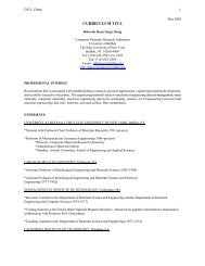
the gap width was decreased to the <strong>molecular</strong> scale. Bycontrolling the electrodeposition (solid grey line), a stable<strong>molecular</strong> scale gap can be formed, as indicated by asteady tunneling current (solid black line). After completingthe fabrication, we thoroughly rinsed the chip <strong>with</strong> 18 MVpure water to remove Au deposition solution <strong>and</strong> dried it out<strong>with</strong> N 2 gas. We then mounted it on a MCBJ setup to furthercontrol the gap or <strong>point</strong> contact mechanically.2.2 CalibrationSince the mechanical control <strong>of</strong> the gap width or <strong>point</strong>contact size is achieved by bending the chip <strong>with</strong> a PZT(AE0203D08 piezoelectric stack, THORLAB Inc.), it isnecessary to calibrate the actual separation <strong>of</strong> the electrodesfor a given amount <strong>of</strong> PZT movement. Displacement ratio r,defined as the ratio <strong>of</strong> the elongation <strong>of</strong> the PZT over theinduced electrode separation, serves this calibrationpurpose. This ratio is given by r ¼ L 2 /3 mH, where L isthe distance between the two counter supports, m is thewidth <strong>of</strong> the trench <strong>and</strong> H is the thickness <strong>of</strong> the substrate(Fig. 1). In our setup, L ¼ 12 mm, m ¼ 10 mm <strong>and</strong>H ¼ 360 mm, the calculated ratio is 1.3 10 4 . To determinethe displacement ratio experimentally, we recordedthe tunneling current while applying a triangular wave tothe PZT driver. Similar displacement ratio was obtainedfrom three different devices, <strong>of</strong> which a typical one isshown in Fig. 3. From the tunneling current, we estimatedthe gap width using relation, I ¼ (2e 2 /h)V * exp(2bd),where I is the tunneling current, e is the electron charge,h is the Planck constant, V is the applied bias voltageacross the gap, d is the gap width <strong>and</strong> b, the tunnelingdecay constant in solution, is in the order <strong>of</strong> 10 nm 21[28]. According to the high <strong>and</strong> low stable tunnelingcurrent in Fig. 3, at a fixed bias voltage <strong>of</strong> 0.01 V, the correspondingelectrode separation was varied by 0.075 nm.Since the sensitivity <strong>of</strong> the PZT is 0.06 mm/V <strong>and</strong> thevoltage change in the PZT drive was 11.5 V, the elongation<strong>of</strong> PZT was determined to be 0.69 mm. Using these parameters,the measured displacement ratio was found to be1 10 4 , which is close to the theoretical estimate. Thisratio is large, so a large PZT movement is demagnifiedinto a small change in the gap width. This is the reasonfor the good stability <strong>of</strong> the setup, but it also limits thetotal adjustable range <strong>of</strong> the gap to 1 nm, <strong>with</strong> themaximum elongation <strong>of</strong> 9 mm <strong>of</strong> PZT in our setup. Theproblem associated <strong>with</strong> this limited mechanicallyFig. 3 Calibration <strong>of</strong> the displacement ratio, rThe PZT driver was modulated <strong>with</strong> a triangular wave (grey colour)<strong>and</strong> the associated tunneling current is recorded vs time (black colour)The bias in the calibration was 0.01 Vadjustable range is solved by combining it <strong>with</strong> electrochemicaletching <strong>and</strong> deposition, which provides an additionalcontrol <strong>of</strong> the size <strong>of</strong> the metal <strong>junctions</strong>. We note that sinceonly a small amount <strong>of</strong> mechanical adjustment is used in oursetup, it reduces the likelihood <strong>of</strong> breaking the Si substrate.We found that if we deposit a large amount <strong>of</strong> metal tobridge the gap, it will require a large mechanical movementto re-open the gap, which <strong>of</strong>ten causes the Si substrate tobreak. The mechanical breakdown <strong>of</strong> the Si substrate wasthe reason that the yield <strong>of</strong> the entire process was around50%, over a total <strong>of</strong> 200 devices. Once a device wasfabricated successfully, it could be used repeatedly. But inorder to minimise possible contamination, we use newdevices daily.2.3 Electron transport in 4,4 0 -bipyridineWe have used this method to study electron transport in4,4 0 -bipyridine. The molecule is terminated <strong>with</strong> two pyridinegroups which can bind to Au electrodes. It is expectedto be relatively conducting due to its conjugated structure.Finally, 4,4 0 -bipyridine is soluble in aqueous solution,which allows us to study the electrochemical gate effect.We performed the conductance measurement by breakingan Au contact in 1 mM 4,4 0 -bipyridine aqueous solution(<strong>with</strong> 0.05 M NaClO 4 as supporting electrolyte for potentialcontrol). During the breaking process, we first observedconductance quantisation associated <strong>with</strong> breakup <strong>of</strong> thegold contact (Fig. 4a). Clean quantisation steps show thatthe Au junction formed by electrodeposition was continuous<strong>and</strong> fresh. When the gold contact was completely broken,steps <strong>with</strong> smaller conductance showed up (Fig. 4b). Ourresults indicate that these steps are due to the formation <strong>of</strong>Au–4,4 0 -bipyridine–Au junction <strong>with</strong> different number <strong>of</strong>molecules trapped between the two Au electrodes. Fig. 4cis a conductance histogram constructed from 180 individualtraces such as those shown in Fig. 4b. A pronouncedconductance peak located at 0.01G 0 was revealed, whichis consistent <strong>with</strong> the previously published STM breakjunction result [29]. Broad width <strong>of</strong> conductance peakreflects the variable molecule–electrode contact geometriesin the formation <strong>of</strong> <strong>molecular</strong> <strong>junctions</strong>.To measure the I–V curves <strong>of</strong> the <strong>molecular</strong> <strong>junctions</strong>,we adjusted the electrode separation by controlling thePZT until the conductance locked on a stable plateau, correspondingto the formation <strong>of</strong> a single molecule junction, <strong>and</strong>then froze the PZT <strong>and</strong> measured the current while sweepingthe bias voltage. The bias range studied here wasbetween 20.4 V <strong>and</strong> þ0.4 V, beyond which the junctionbecame increasingly unstable. This instability is likely dueto the fact that the N–Au binding is relatively weak <strong>and</strong>4,4 0 -bipyridine desorbs from Au surfaces at negative potentials.We found that if thiol anchoring groups are used tobridge molecules to Au electrodes, the bias voltage rangecould be exp<strong>and</strong>ed to +1.2 V, due to stronger S–Aubinding. For comparison, the I–V data previously obtained<strong>with</strong> an STM setup [29] is also shown as grey solid squares,which shows that the two methods are consistent <strong>with</strong> eachother (Fig. 5a).We have studied the electrochemical gate effect on theconductance <strong>of</strong> single 4,4 0 -bipyridine <strong>with</strong> the setup. Theelectrochemical gate was controlled by a homemadebipotentiostat using a Pt wire as the counter electrode <strong>and</strong>an Ag wire as the quasi-reference electrode. The quasi referenceelectrode was calibrated against the more commonlyused Ag/AgCl (in 3.5 M KCl) reference electrode. Tomeasure the gate effect, we created a stable 4,4 0 -bipyridinejunction <strong>and</strong> then monitored the current through theMicro & Nano Letters, Volume 1, Issue 2 85
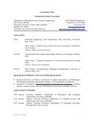
Fig. 4 Conductance quantisation <strong>of</strong> Aua Au quantisation steps near integer multiples <strong>of</strong> G 0 ¼ 2e 2 /h as the Aujunction was elongated into an <strong>atomic</strong> <strong>point</strong> contactb After the Au <strong>atomic</strong> <strong>point</strong> contact was broken, a new set <strong>of</strong> conductancesteps showed up in presence <strong>of</strong> 4,4 0 -bipyridineThe steps are due to the formation <strong>of</strong> Au–4,4 0 -bipyridine–Au<strong>junctions</strong>c Conductance histogram <strong>of</strong> 4,4 0 -bipyridine constructed from 180individual curves displays conductance peak at 0.01G 0 <strong>and</strong> 0.02G 0Grey solid lines are the Gaussian fittingBias was 0.1 V in the measurementmolecule while sweeping the electrochemical gate voltage,during which the bias voltage between two Au electrodeswas fixed at 0.1 V. A typical source-drain current (I sd )against gate voltage (V g ) curve is shown in Fig. 5b.Source-drain current increased 25%, as the gate voltagewas swept negatively. There was a run-to-run variation,but statistical analysis based on 17 different <strong>junctions</strong>showed only a small electrochemical gate effect (Fig. 5c).To verify the weak gate effect on 4,4 0 -bipyridine, wecarried out a series <strong>of</strong> control experiments: (1) Wechanged the sweeping rate <strong>of</strong> the electrochemical gatevoltage <strong>and</strong> found no obvious dependence <strong>of</strong> the gateinducedconductance change on the sweep rate, which indicatesthat the gate effect is not due to a capacitive chargingprocess. (2) We also measured the tunneling current across a86Fig. 5 Electrical characteristics <strong>of</strong> 4,4 0 -bipyridineaI–V curves <strong>of</strong> single 4,4 0 -bipyridine obtained by MCBJ method bysweeping bias voltage (black solid lines) <strong>and</strong> from the positions <strong>of</strong>the peaks in the conductance histograms by Scanning TunnelingMicroscope (STM) break <strong>junctions</strong> (grey solid squares)b A typical source-drain current (I sd ) as a function <strong>of</strong> electrochemicalgate voltage (V g ) <strong>of</strong> a 4,4 0 -bipyridine <strong>molecular</strong> junction in 0.05 MNaClO 4The gate voltage was swept from 20.2 V to þ0.6 V against Ag/AgClCorresponding ionic leakage current is shown as grey solid line forcomparisonc Statistic <strong>of</strong> the current change <strong>of</strong> 17 individual curves shown in bBias was fixed at 0.1 V in the measurementpair <strong>of</strong> bare electrodes (<strong>with</strong>out the presence <strong>of</strong> molecules)as a function <strong>of</strong> electrochemical gate voltage <strong>and</strong> observedno significant change in the tunneling current. (3) To eliminateionic leakage current as a possible cause for the gateeffect, we measured the current between the two electrodesby separating them far apart to ensure no tunneling electronsMicro & Nano Letters, Volume 1, Issue 2
can flow between the electrodes. The current was typicallywell below 0.2 nA in the electrolyte shown as the grey solidline in Fig. 5b, much smaller than the conduction currentthrough the <strong>molecular</strong> junction. The electrochemical gateeffect observed here is rather weak, which could be partiallydue to the screening <strong>of</strong> the gate field by the proximity <strong>of</strong> thetwo electrodes (serving as source <strong>and</strong> drain).3 Ni <strong>atomic</strong> <strong>point</strong> contactThe same setup can create <strong>atomic</strong> <strong>point</strong> <strong>contacts</strong> by eithermechanically controlling the elongation <strong>of</strong> the Au electrodesor by electrodeposition/etching process (Fig. 4a). Theuse <strong>of</strong> electrodeposition makes it easy to fabricate <strong>atomic</strong><strong>point</strong> <strong>contacts</strong> <strong>of</strong> different metals, <strong>and</strong> even a <strong>point</strong>contact between two different metals. To demonstrate thisapplication, we have fabricated Ni <strong>atomic</strong> <strong>point</strong> <strong>contacts</strong>using this combined approach. The first step is to electrochemicallydeposit Ni onto Au electrodes by holding thepotentials <strong>of</strong> the two electrodes at 21.1 V against Ag/AgCl <strong>with</strong> 0.1 M nickel sulphamate in 0.5 M boric acid(pH 3.5). We can also choose to deposit Ni onto only one<strong>of</strong> the two electrodes to fabricate an Au–Ni contact. Aftera <strong>point</strong> contact is formed, we can further control the size<strong>of</strong> the <strong>atomic</strong> <strong>point</strong> contact mechanically. Since Ni is aferromagnetic material <strong>with</strong> partial occupied d-orbital, ithas been argued that the strong exchange splitting <strong>of</strong> theelectron b<strong>and</strong>s may lift the spin degeneracy. The up- <strong>and</strong>down-spin electrons contribute independently to the electrictransport, which results in the conductance <strong>of</strong> <strong>atomic</strong> <strong>point</strong>contact located at integer multiples <strong>of</strong> e 2 /h. In the preliminaryexperiments, we have performed the measurement<strong>with</strong> a magnetic field (0.4 T). A typical conductancetrace is shown in Fig. 6a. Unlike the results <strong>with</strong>out a magneticfield (result not shown), steps near or at integer multiples<strong>of</strong> e 2 /h have rather frequently been observed in Ni<strong>point</strong> <strong>contacts</strong>. The conductance histogram (Fig. 6b) constructedfrom 18 individual curves from two differentdevices shows some evidence <strong>of</strong> conductance peakslocated at integer multiples <strong>of</strong> e 2 /h [30–32]. Furtherstudies are in progress to verify <strong>and</strong> underst<strong>and</strong> the preliminaryfindings.4 SummaryWe have described a combined mechanical <strong>and</strong> electrochemicaldeposition method to fabricate <strong>atomic</strong> <strong>point</strong> <strong>contacts</strong><strong>and</strong> <strong>molecular</strong> <strong>junctions</strong>. Using the method, we have created<strong>atomic</strong> <strong>point</strong> <strong>contacts</strong> <strong>and</strong> studied electron transport through4,4 0 -bipyridine. The setup is particularly suitable for studying<strong>atomic</strong> <strong>point</strong> <strong>contacts</strong> <strong>and</strong> <strong>molecular</strong> <strong>junctions</strong> inaqueous solutions, which is required for biologically relevantmolecules, <strong>molecular</strong> binding events <strong>and</strong> electrochemicalgate-control <strong>of</strong> single molecule conductance.5 AcknowledgmentsWe would like to thank Bingqian Xu <strong>and</strong> Joshua Hihath forthe help <strong>and</strong> acknowledge the financial support fromNSF-DMR-03-05242.6 ReferencesFig. 6 Conductance quantisation <strong>of</strong> Nia Conductance quantisation steps <strong>of</strong> a Ni <strong>atomic</strong> <strong>point</strong> contact. Thequantised conductance steps are located at integer multiples <strong>of</strong> e 2 /hb Conductance histogram constructed from 18 individual curves asshown in a1 Li, C.Z., Bogozi, A., Huang, W., <strong>and</strong> Tao, N.J.: ‘Fabrication <strong>of</strong> stablemetallic nanowires <strong>with</strong> quantized conductance’, Nanotechnology,1999, 10, pp. 221–2232 Morpurgo, A.F., Marcus, C.M., <strong>and</strong> Robinson, D.B.: ‘Controlledfabrication <strong>of</strong> metallic electrodes <strong>with</strong> <strong>atomic</strong> separation’, Appl.Phys. Lett., 1999, 14, p. 20823 Kervennic, Y.V., Thijssen, J.M., Vanmaekelbergh, D., Dabirian, R.,Jenneskens, L.W., van Walree, C.A., <strong>and</strong> van der Zant, H.S.J.:‘Charge transport in three-terminal <strong>molecular</strong> <strong>junctions</strong> incorporatingsulfur-end-functionalized tercyclohexylidene spacers’, Angew. Chem.Int. Ed. Engl., 2006, 45, pp. 2540–25424 Li, X.L., He, H.X., Xu, B.Q., Xiao, X., Tsui, R., Nagahara, L.A.,Amlani, I., <strong>and</strong> Tao, N.J.: ‘Electron transport properties <strong>of</strong>electrochemically <strong>and</strong> mechanically formed <strong>molecular</strong> <strong>junctions</strong>’,Surf. Sci., 2004, 573, pp. 1–105 Park, J., Pasupathy, A.N., Goldsmith, J.L., Chang, C., Yaish, Y., Petta,J.R., Rinkoski, M., Sethna, J.P., Abruna, H.D., McEuen, P.L., <strong>and</strong>Ralph, D.C.: ‘Coulomb blockade <strong>and</strong> the Kondo effect insingle-atom transistors’, Nature, 2002, 417, pp. 722–7256 Liang, W.J., Shores, M., Bockrath, M., Long, J.R., <strong>and</strong> Park, H.:‘Kondo resonance in a single-molecule transistor’, Nature, 2002,417, pp. 725–7297 Lee, J.-O., Lientschnig, G., Wiertz, F., Struijk, M., Janssen, R.A.J.,Egberink, R., Reinhoudt, D.N., Hadley, P., <strong>and</strong> Dekker, C.:‘Absence <strong>of</strong> strong gate effects in electrical measurements onphenylene-based conjugated molecules’, Nano Lett., 2003, 3,pp. 113–1178 Luber, S.M., Strobel, S., Tranitz, H.P., Wegscheider, W., Schuh, D.,<strong>and</strong> Tornow, M.: ‘Nanometre spaced electrodes on a cleavedAlGaAs surface’, Nanotechnology, 2005, 16, pp. 1182–11859 Kubatkin, S., Danilov, A., Hjort, M., Cornil, J., Bredas, J.-L.,Stuhr-Hansen, N., Hedegard, P., <strong>and</strong> Bjornholm, T.: ‘Single-electrontransistor <strong>of</strong> a single organic molecule <strong>with</strong> access to several redoxstates’, Nature, 2003, 425, pp. 698–70110 Zhitenev, N.B., Meng, H., <strong>and</strong> Bao, Z.: ‘Conductance <strong>of</strong> small<strong>molecular</strong> <strong>junctions</strong>’, Phys. Rev. Lett., 2002, 92, pp. 186805/186801–186805/18680411 Ghosh, S., Halimun, H., Mahapatro, A.K., Choi, J., Lodha, S., <strong>and</strong>Janes, D.: ‘Device structure for electronic transport throughindividual molecules using nanoelectrodes’, Appl. Phys. Lett., 2005,87, p. 233509Micro & Nano Letters, Volume 1, Issue 2 87
12 Gimzewski, J.K., <strong>and</strong> Moller, R.: ‘Transition from the tunnelingregime to <strong>point</strong> contact studied using scanning tunnelingmicroscopy’, Phys. Rev. B, 1987, 36, pp. 1284–128713 Pascual, J.I., Mendez, J., Gomez-Herrero, J., Baro, A.M., Garcia, N.,<strong>and</strong> Binh, V.T.: ‘Quantum contact in gold nanostructures by scanningtunneling microscopy’, Phys. Rev. Lett., 1993, 71, pp. 1852–185514 Krans, J.M., Ruitenbeek, J.M.v., Fisun, V.V., Yanson, I.K., <strong>and</strong> Jongh,L.J.d.: ‘The signature <strong>of</strong> condutance quantization in metallic <strong>point</strong><strong>contacts</strong>’, Nature, 1995, 375, pp. 767–76915 Agrait, N., Rodrigo, J.G., <strong>and</strong> Vieira, S.: ‘Conductance steps <strong>and</strong>quantization in <strong>atomic</strong>-size <strong>contacts</strong>’, Phys. Rev. B, 1993, 52,pp. 12345–1234816 Yanson, A.I., Rubio, Bollinger G., van den Brom, H.E., Agrait, N.,<strong>and</strong> van Ruitenbeek, J.M.: ‘<strong>Formation</strong> <strong>and</strong> manipulation <strong>of</strong> ametallic wire <strong>of</strong> single gold atoms’, Nature, 1998, 395, pp. 783–78517 Garcia, N., Munoz, M., <strong>and</strong> Zhao, Y.-W.: ‘Magnetoresistance inexcess <strong>of</strong> 200% in ballistic Ni nano<strong>contacts</strong> at room temperature<strong>and</strong> 100 Oe’, Phys. Rev. Lett., 1999, 82, pp. 2923–292618 Chopra, H.D., <strong>and</strong> Hua, S.Z.: ‘Ballistic magnetoresistance over3000% in Ni nano<strong>contacts</strong> at room temperature’, Phys. Rev. B,2002, 66, p. 02040319 Chopra, H.D., Sullivan, M.R., Armstrong, J.N., <strong>and</strong> Hua, S.Z.: ‘Thequantum spin-valve in cobalt <strong>atomic</strong> <strong>point</strong> <strong>contacts</strong>’, Nature Mater.,2005, 4, pp. 832–83720 Morel<strong>and</strong>, J., <strong>and</strong> Ekin, J.W.: ‘Electron tunneling experimentsusing Nb–Sn break <strong>junctions</strong>’, J. Appl. Phys., 1985, 58,pp. 3888–389521 Muller, C.J., van Ruitenbeek, J.M., <strong>and</strong> de Jongh, L.J.: ‘Conductance<strong>and</strong> supercurrent discontinuities in <strong>atomic</strong>-scale metallic constrictions<strong>of</strong> variable width’, Phys. Rev. Lett., 1992, 69, pp. 140–14322 Ruitenbeek, J.M.v., Allvarez, A., Pineyro, I., Grahmann, C., Joyez, P.,Devoret, M.H., Esteve, E., <strong>and</strong> Urbina, C.: ‘Adjustable nan<strong>of</strong>abricated<strong>atomic</strong> size <strong>contacts</strong>’, Rev. Sci. Instrum., 1996, 67, pp. 108–11123 Li, C.Z., <strong>and</strong> Tao, N.J.: ‘Quantum transport in metallic nanowiresfabricated by electrochemical deposition/dissolution’, Appl. Phys.Lett., 1998, 72, pp. 894–89724 Xiang, J., Liu, B., Wu, S.T., Ren, B., Yang, F.Z., Mao, B.W., Chow,Y.L., <strong>and</strong> Tian, Z.Q.: ‘A controllable electrochemical fabrication <strong>of</strong>metallic electrodes <strong>with</strong> a nanometer/angstrom-sized gap using anelectric double layer as feedback’, Angew. Chem. Int. Ed., 2005, 44,pp. 1265–126825 Qing, Q., Chen, F., Li, P.G., Tang, W.H., Wu, Z.Y., <strong>and</strong> Liu, Z.F.:‘Finely tuning metallic nanogap size <strong>with</strong> electrodeposition byutilizing high-frequency impedance in feedback’, Angew. Chem. Int.Ed., 2005, 44, pp. 7771–777526 Deshmukh, M.M., Prieto, A.L., Gu, Q., <strong>and</strong> Park, H.: ‘Fabrication <strong>of</strong>asymmetric electrode pairs <strong>with</strong> nanometer separation made <strong>of</strong> twodistinct metals’, Nano Lett., 2003, 3, pp. 1383–138527 Champagne, A.R., Pasupathy, A.N., <strong>and</strong> Ralph, D.C.: ‘Mechanicallyadjustable <strong>and</strong> electrically gated single-molecule transistors’, NanoLett., 2005, 5, pp. 305–30828 Vaught, A., Jing, T.W., <strong>and</strong> Lindsay, S.M.: ‘Nonexponential tunnelingin water near an electrode’, Chem. Phys. Lett., 1995, 236, pp. 306–31029 Xu, B.Q., <strong>and</strong> Tao, N.J.: ‘Measurement <strong>of</strong> single moleculeconductance by repeated formation <strong>of</strong> <strong>molecular</strong> <strong>junctions</strong>’, Science,2003, 301, pp. 1221–122330 Elhoussine, F., Matefi-Tempfli, S., Encinas, A., <strong>and</strong> Piraux, L.:‘Conductance quantization in magnetic nanowires electrodepositedin nanopores’, Appl. Phys. Lett., 2002, 81, pp. 1681–168331 Ono, T., Ooka, Y., Miyajima, H., <strong>and</strong> Otani, Y.: ‘2e(2)/h to e(2)/hswitching <strong>of</strong> quantum conductance associated <strong>with</strong> a change innanoscale ferromagnetic domain structure’, Appl. Phys. Lett., 1999,75, pp. 1622–162432 Shimizu, M., Saitoh, E., Miyajima, H., <strong>and</strong> Otani, Y.: ‘Conductancequantization in ferromagnetic Ni nano-constriction’, J. Magn. Magn.Mater., 2002, 239, pp. 243–24588Micro & Nano Letters, Volume 1, Issue 2