- Page 1 and 2:
May 13, 2003United Statesconfigurat
- Page 3 and 4:
Table of ContentsInformation Source
- Page 5 and 6:
United StatesAudience Where to go H
- Page 7 and 8:
When in a competitive situation, th
- Page 9:
IBM xSeries Selection GuideApplicat
- Page 13 and 14:
IntelliStation® Video Adapter Sele
- Page 15 and 16:
IntelliStation E Pro 6216 MemoryPar
- Page 17 and 18:
IntelliStation E Pro 6216 I/O Optio
- Page 19 and 20:
IntelliStation E Pro 6226 MemoryPar
- Page 21 and 22:
IntelliStation E Pro 6226 I/O Optio
- Page 23 and 24:
IntelliStation M Pro 6219Part Numbe
- Page 25 and 26:
IntelliStation M Pro 6219 Hard Disk
- Page 27 and 28:
IntelliStation M Pro 6219 I/O Optio
- Page 29 and 30:
IntelliStation M Pro 6219 Tape Opti
- Page 31 and 32:
IntelliStation Z Pro 6221 Processor
- Page 33 and 34:
Bay Form Factor Height Front Access
- Page 35 and 36:
Z Pro 6221 front viewAGP slotPCI sl
- Page 37 and 38:
xSeries 205Part Number 1Processor S
- Page 39 and 40:
xSeries 205 Hard Disk Drive (HDD)SC
- Page 41 and 42:
.Bay 1: CD-ROMBay 2Bay 3: FDDBay 4B
- Page 43 and 44:
xSeries 205 Power, Monitors & Acces
- Page 45 and 46:
xSeries 205 Sample ConfigurationsNo
- Page 47 and 48:
xSeries 225 ProcessorsPartSMPProces
- Page 49 and 50:
Hot-swap SCSI modelsTotal36.4GB36.4
- Page 51 and 52:
xSeries 225 I/O OptionsPartAdapter
- Page 53 and 54:
Part Number59P4817DescriptionConver
- Page 55 and 56:
xSeries 225 Sample ConfigurationsNo
- Page 57 and 58:
xSeries 235Part Number 1Processor S
- Page 59 and 60:
Total System Memor y 1 Quantity of
- Page 61 and 62:
PartNumberDescription RPM HeightBay
- Page 63 and 64:
onboard SCSI controller to RAID in
- Page 65 and 66:
PartNumberDescriptionConversion Kit
- Page 67 and 68:
xSeries 235 Sample ConfigurationsNo
- Page 69 and 70:
xSeries 255 Processor UpgradesProce
- Page 71 and 72:
xSeries 255 Hard Disk Drive (HDD) S
- Page 73 and 74:
Bay Form Factor Height Front Access
- Page 75 and 76:
37L6861 APC Smart-UPS 5000RMB 5 Mon
- Page 77 and 78:
xSeries 255 Tape OptionsPartNumberT
- Page 79 and 80:
File and Print Server (large user b
- Page 81 and 82:
xSeries 305 MemoryPart Number Memor
- Page 83 and 84:
PartNumberDescription RPM HeightBay
- Page 85 and 86:
37L6861 APC Smart-UPS 5000RMB 4 Mon
- Page 87 and 88:
xSeries 305 Sample ConfigurationsNo
- Page 89 and 90:
xSeries 335 ProcessorsPartSMPProces
- Page 91 and 92:
PartNumberDescription RPM HeightBay
- Page 93 and 94:
PCI slot 2PCI slot 1xSeries 335 rea
- Page 95 and 96:
Linux Cluster Node 1Part Number Des
- Page 97 and 98:
xSeries 343 Internal SCSI CablingTh
- Page 99 and 100:
xSeries 345Part Number 1Processor S
- Page 101 and 102:
xSeries 345 Hard Disk Drive (HDD) S
- Page 103 and 104:
PartNumberDescriptionAdapterLengthP
- Page 105 and 106:
Part NumberDescriptionRack and NetB
- Page 107 and 108:
xSeries 345 Sample ConfigurationsNo
- Page 109 and 110:
xSeries 360 MemoryPartNumberMemory
- Page 111 and 112:
xSeries 360 I/O OptionsPartNumberDe
- Page 113 and 114:
The following table is provided as
- Page 115 and 116:
xSeries 360 Sample ConfigurationsNo
- Page 117 and 118:
9. Advanced Chipkill ECC memory con
- Page 119 and 120:
Logical diagram of SMP Expansion Mo
- Page 121 and 122:
xSeries 440 Hard Disk Drive (HDD) S
- Page 123 and 124:
PartAdapter PCI Slots Hot- PCI Volt
- Page 125 and 126:
Part NumberDescriptionRack and NetB
- Page 127 and 128:
Microsoft Exchange High-availabilit
- Page 129 and 130:
xSeries 450 MemoryPartNumberMemory
- Page 131 and 132:
xSeries 450 Hard Disk Drive (HDD) S
- Page 133 and 134:
PartAdapter PCI Slots Hot- PCI Volt
- Page 135 and 136:
xSeries 450 Tape OptionsPartNumberT
- Page 137 and 138:
RXE-100 Remote Expansion Enclosure
- Page 139 and 140:
RXE-100 Remote Expansion Enclosure
- Page 141 and 142:
Datacenter Solution ProgramThe IBM
- Page 143 and 144:
IBM Datacenter Solution - Single No
- Page 145 and 146:
IBM Datacenter Solution - 16-wayBun
- Page 147 and 148:
IBM Datacenter Solution - Selectabl
- Page 149 and 150:
BladeCenterOption Part NumberForm F
- Page 151 and 152:
BladeCenter Storage and Communicati
- Page 153 and 154:
Updated 05/13/03For the latest prod
- Page 155 and 156:
HS20 ProcessorsOption PartSMP SBBPr
- Page 157 and 158:
32P0734 36.4GB 15Krpm Ultra320 SCSI
- Page 159 and 160:
External Storage Expansion Unit Ove
- Page 161 and 162:
SCSI ID Form Factor Height Front Ac
- Page 163 and 164:
Fibre Channel Solutions OverviewPar
- Page 165 and 166:
FAStT200 Storage Server (3542xRU)FA
- Page 167 and 168:
Fibre / Fibre Configuration Example
- Page 169 and 170:
FAStT EXP500 (35601RU)FAStT EXP500
- Page 171 and 172:
Fibre / Fibre Configuration Example
- Page 173 and 174: FAStT600 Storage ServerFAStT600 Sto
- Page 175 and 176: Fibre Channel Configuration Example
- Page 177 and 178: PartNumberDescription RPM HeightBay
- Page 179 and 180: 1.FC2-133 HostBus Adapter 1FC2-133
- Page 181 and 182: Fibre Device Ports ReferencePartNum
- Page 183 and 184: FAStT200 Storage Server (P/N 35421R
- Page 185 and 186: Rack Cabinets and OptionsIBM NetBAY
- Page 187 and 188: IBM Rack-Mounted UnitsStandard Powe
- Page 189 and 190: PartNumberDescriptionRack OptionsIn
- Page 191 and 192: Rack Console OptionsA console consi
- Page 193 and 194: Refer to the cable labeling key in
- Page 195 and 196: INSwitch OptionsPorts Capacity Stan
- Page 197 and 198: Typical Rack Power ConfigurationsSi
- Page 199 and 200: Power Cables(1) Device to Rack PDU
- Page 201 and 202: Country Specific Considerations: Ja
- Page 203 and 204: Updated 05/13/03Rack PDUsOption Par
- Page 205 and 206: Appendix A: Tape Drive AttributesTa
- Page 207 and 208: Appendix B: Tape Library Attributes
- Page 209 and 210: INT’LP/NUSP/NSU-700iNET94G4073SU-
- Page 211 and 212: Tower or Rack MountInternationalPar
- Page 213 and 214: Appendix D: SCSI Cables -Storage Un
- Page 215 and 216: Updated 05/13/03For the latest prod
- Page 217 and 218: Appendix G: System Management Overv
- Page 219 and 220: 28. xSeries 335 includes new interc
- Page 221 and 222: Updated 05/13/03xSeries Advanced Sy
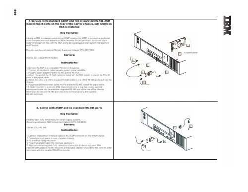
- Page 223: Updated 05/13/035. Server with ISMP
- Page 227 and 228: 8684-1RX RXE-100 Remote Expansion E
- Page 229: © Copyright IBM Corporation 2003IB