IBM System x3500 Type 7977: Problem ... - IBM Quicklinks
IBM System x3500 Type 7977: Problem ... - IBM Quicklinks
IBM System x3500 Type 7977: Problem ... - IBM Quicklinks

You also want an ePaper? Increase the reach of your titles
YUMPU automatically turns print PDFs into web optimized ePapers that Google loves.
<strong>IBM</strong> <strong>System</strong> <strong>x3500</strong> <strong>Type</strong> <strong>7977</strong><strong>Problem</strong> Determination and Service Guide
<strong>IBM</strong> <strong>System</strong> <strong>x3500</strong> <strong>Type</strong> <strong>7977</strong><strong>Problem</strong> Determination and Service Guide
NoteBefore using this information and the product it supports, read the general information in Appendix B, “Notices,” on page 123.Fifth Edition (November 2006)© Copyright International Business Machines Corporation 2006. All rights reserved.US Government Users Restricted Rights – Use, duplication or disclosure restricted by GSA ADP Schedule Contractwith <strong>IBM</strong> Corp.
ContentsSafety . . . . . . . . . . . . . . . . . . . . . . . . . . . . viiChapter 1. Introduction . . . . . . . . . . . . . . . . . . . . . . 1Related documentation . . . . . . . . . . . . . . . . . . . . . . 1Notices and statements in this document . . . . . . . . . . . . . . . . 2Features and specifications . . . . . . . . . . . . . . . . . . . . . 3Server controls, LEDs, and connectors . . . . . . . . . . . . . . . . 4Front view . . . . . . . . . . . . . . . . . . . . . . . . . . 4Rear view . . . . . . . . . . . . . . . . . . . . . . . . . . 6Internal LEDs, connectors, and jumpers . . . . . . . . . . . . . . . . 8<strong>System</strong>-board internal connectors and switches . . . . . . . . . . . . 8<strong>System</strong>-board LEDs . . . . . . . . . . . . . . . . . . . . . . 10<strong>System</strong>-board external connectors . . . . . . . . . . . . . . . . . 10SAS backplane . . . . . . . . . . . . . . . . . . . . . . . . 11Chapter 2. Diagnostics . . . . . . . . . . . . . . . . . . . . . 13Diagnostic tools . . . . . . . . . . . . . . . . . . . . . . . . 13POST . . . . . . . . . . . . . . . . . . . . . . . . . . . . 13POST beep codes . . . . . . . . . . . . . . . . . . . . . . 13Error logs . . . . . . . . . . . . . . . . . . . . . . . . . . 17POST error codes . . . . . . . . . . . . . . . . . . . . . . . 19Checkout procedure . . . . . . . . . . . . . . . . . . . . . . . 29About the checkout procedure . . . . . . . . . . . . . . . . . . 29Performing the checkout procedure . . . . . . . . . . . . . . . . 29Checkpoint codes (trained service technicians only) . . . . . . . . . . . 30Troubleshooting tables . . . . . . . . . . . . . . . . . . . . . . 30DVD drive problems . . . . . . . . . . . . . . . . . . . . . . 31General problems . . . . . . . . . . . . . . . . . . . . . . . 32Hard disk drive problems . . . . . . . . . . . . . . . . . . . . 32Intermittent problems . . . . . . . . . . . . . . . . . . . . . . 33Keyboard, mouse, or pointing-device problems . . . . . . . . . . . . 33Memory problems . . . . . . . . . . . . . . . . . . . . . . . 35Microprocessor problems . . . . . . . . . . . . . . . . . . . . 36Monitor problems . . . . . . . . . . . . . . . . . . . . . . . 36Optional-device problems . . . . . . . . . . . . . . . . . . . . 39Power problems . . . . . . . . . . . . . . . . . . . . . . . 40Serial port problems . . . . . . . . . . . . . . . . . . . . . . 41ServerGuide problems . . . . . . . . . . . . . . . . . . . . . 41Software problems . . . . . . . . . . . . . . . . . . . . . . 42Universal Serial Bus (USB) port problems . . . . . . . . . . . . . . 43Video problems . . . . . . . . . . . . . . . . . . . . . . . . 43Light path diagnostics . . . . . . . . . . . . . . . . . . . . . . 43Remind button . . . . . . . . . . . . . . . . . . . . . . . . 45Light path diagnostics LEDs . . . . . . . . . . . . . . . . . . . 45Power-supply LEDs . . . . . . . . . . . . . . . . . . . . . . . 49Diagnostic programs, messages, and error codes . . . . . . . . . . . . 50Running the diagnostic programs . . . . . . . . . . . . . . . . . 50Diagnostic text messages . . . . . . . . . . . . . . . . . . . . 52Viewing the test log . . . . . . . . . . . . . . . . . . . . . . 52Diagnostic error codes . . . . . . . . . . . . . . . . . . . . . 52<strong>System</strong>-error log messages . . . . . . . . . . . . . . . . . . . . 61Solving power problems . . . . . . . . . . . . . . . . . . . . . 71Solving Ethernet controller problems . . . . . . . . . . . . . . . . . 71© Copyright <strong>IBM</strong> Corp. 2006 iii
Solving undetermined problems . . . . . . . . . . . . . . . . . . . 72Calling <strong>IBM</strong> for service . . . . . . . . . . . . . . . . . . . . . . 73Chapter 3. Parts listing, <strong>Type</strong> <strong>7977</strong> . . . . . . . . . . . . . . . . . 75Server replaceable units . . . . . . . . . . . . . . . . . . . . . 76Power cords . . . . . . . . . . . . . . . . . . . . . . . . . . 78Chapter 4. Removing and replacing server components . . . . . . . . 81Installation guidelines . . . . . . . . . . . . . . . . . . . . . . 81<strong>System</strong> reliability guidelines . . . . . . . . . . . . . . . . . . . 82Working inside the server with the power on . . . . . . . . . . . . . 82Handling static-sensitive devices . . . . . . . . . . . . . . . . . 82Returning a device or component . . . . . . . . . . . . . . . . . 83Removing the left-side cover and bezel . . . . . . . . . . . . . . . . 83Replacing the left-side cover and bezel . . . . . . . . . . . . . . . . 84Turning the stabilizing feet . . . . . . . . . . . . . . . . . . . . . 85Tier 1 CRU information . . . . . . . . . . . . . . . . . . . . . . 86Battery . . . . . . . . . . . . . . . . . . . . . . . . . . . 86DVD Drive . . . . . . . . . . . . . . . . . . . . . . . . . 87Hot-swap fan . . . . . . . . . . . . . . . . . . . . . . . . 88Memory module . . . . . . . . . . . . . . . . . . . . . . . 91Hot-swap power supply . . . . . . . . . . . . . . . . . . . . . 96Power supply docking cable . . . . . . . . . . . . . . . . . . . 97USB cable assembly . . . . . . . . . . . . . . . . . . . . . . 98Tier 2 CRU information . . . . . . . . . . . . . . . . . . . . . 100DIMM air duct . . . . . . . . . . . . . . . . . . . . . . . . 100Light Path panel . . . . . . . . . . . . . . . . . . . . . . . 101Control panel assembly . . . . . . . . . . . . . . . . . . . . 102ServeRAID-8k adapter . . . . . . . . . . . . . . . . . . . . 103FRU information . . . . . . . . . . . . . . . . . . . . . . . . 104Power-supply cage . . . . . . . . . . . . . . . . . . . . . . 104SAS backplane . . . . . . . . . . . . . . . . . . . . . . . 105<strong>System</strong> board and microprocessor . . . . . . . . . . . . . . . . 106Chapter 5. Configuration information and instructions . . . . . . . . . 111Updating the firmware . . . . . . . . . . . . . . . . . . . . . . 111Configuring the server . . . . . . . . . . . . . . . . . . . . . . 111Using the ServerGuide Setup and Installation CD . . . . . . . . . . . 112Using the Configuration/Setup Utility program . . . . . . . . . . . . 112Installing and using the baseboard management controller utility programs 117Using the SAS/SATA Configuration Utility program . . . . . . . . . . 118Configuring the Ethernet controller . . . . . . . . . . . . . . . . 118Using the ServeRAID Manager . . . . . . . . . . . . . . . . . 118Appendix A. Getting help and technical assistance . . . . . . . . . . 121Before you call . . . . . . . . . . . . . . . . . . . . . . . . 121Using the documentation . . . . . . . . . . . . . . . . . . . . . 121Getting help and information from the World Wide Web . . . . . . . . . 122Software service and support . . . . . . . . . . . . . . . . . . . 122Hardware service and support . . . . . . . . . . . . . . . . . . . 122Appendix B. Notices . . . . . . . . . . . . . . . . . . . . . . 123Edition notice . . . . . . . . . . . . . . . . . . . . . . . . . 123Trademarks . . . . . . . . . . . . . . . . . . . . . . . . . . 124Important notes . . . . . . . . . . . . . . . . . . . . . . . . 124Product recycling and disposal . . . . . . . . . . . . . . . . . . 125iv <strong>IBM</strong> <strong>System</strong> <strong>x3500</strong> <strong>Type</strong> <strong>7977</strong>: <strong>Problem</strong> Determination and Service Guide
Battery return program . . . . . . . . . . . . . . . . . . . . . 126Electronic emission notices . . . . . . . . . . . . . . . . . . . . 127Federal Communications Commission (FCC) statement . . . . . . . . 127Industry Canada Class A emission compliance statement . . . . . . . . 127Avis de conformité à la réglementation d’Industrie Canada . . . . . . . 127European Union EMC Directive conformance statement . . . . . . . . 128Japanese Voluntary Control Council for Interference (VCCI) statement 128Index . . . . . . . . . . . . . . . . . . . . . . . . . . . . 129Contentsv
vi <strong>IBM</strong> <strong>System</strong> <strong>x3500</strong> <strong>Type</strong> <strong>7977</strong>: <strong>Problem</strong> Determination and Service Guide
SafetyBefore installing this product, read the Safety Information.Antes de instalar este produto, leia as Informações de Segurança.Pred instalací tohoto produktu si prectete prírucku bezpecnostních instrukcí.Læs sikkerhedsforskrifterne, før du installerer dette produkt.Lees voordat u dit product installeert eerst de veiligheidsvoorschriften.Ennen kuin asennat tämän tuotteen, lue turvaohjeet kohdasta Safety Information.Avant d’installer ce produit, lisez les consignes de sécurité.Vor der Installation dieses Produkts die Sicherheitshinweise lesen.Prima di installare questo prodotto, leggere le Informazioni sulla Sicurezza.Les sikkerhetsinformasjonen (Safety Information) før du installerer dette produktet.Antes de instalar este produto, leia as Informações sobre Segurança.Antes de instalar este producto, lea la información de seguridad.Läs säkerhetsinformationen innan du installerar den här produkten.Important:© Copyright <strong>IBM</strong> Corp. 2006 vii
All caution and danger statements in this documentation begin with a number. Thisnumber is used to cross reference an English caution or danger statement withtranslated versions of the caution or danger statement in the <strong>IBM</strong> Safety Informationbook.For example, if a caution statement begins with a number 1, translations for thatcaution statement appear in the <strong>IBM</strong> Safety Information book under statement 1.Be sure to read all caution and danger statements in this documentation beforeperforming the instructions. Read any additional safety information that comes withthe server or optional device before you install the device.viii <strong>IBM</strong> <strong>System</strong> <strong>x3500</strong> <strong>Type</strong> <strong>7977</strong>: <strong>Problem</strong> Determination and Service Guide
Statement 1:DANGERElectrical current from power, telephone, and communication cables ishazardous.To avoid a shock hazard:v Do not connect or disconnect any cables or perform installation,maintenance, or reconfiguration of this product during an electricalstorm.v Connect all power cords to a properly wired and grounded electricaloutlet.v Connect to properly wired outlets any equipment that will be attached tothis product.v When possible, use one hand only to connect or disconnect signalcables.v Never turn on any equipment when there is evidence of fire, water, orstructural damage.v Disconnect the attached power cords, telecommunications systems,networks, and modems before you open the device covers, unlessinstructed otherwise in the installation and configuration procedures.v Connect and disconnect cables as described in the following table wheninstalling, moving, or opening covers on this product or attacheddevices.To Connect: To Disconnect:1. Turn everything OFF.2. First, attach all cables to devices.3. Attach signal cables to connectors.4. Attach power cords to outlet.5. Turn device ON.1. Turn everything OFF.2. First, remove power cords from outlet.3. Remove signal cables from connectors.4. Remove all cables from devices.Safetyix
Statement 2:CAUTION:When replacing the lithium battery, use only <strong>IBM</strong> Part Number 33F8354 or anequivalent type battery recommended by the manufacturer. If your system hasa module containing a lithium battery, replace it only with the same moduletype made by the same manufacturer. The battery contains lithium and canexplode if not properly used, handled, or disposed of.Do not:v Throw or immerse into waterv Heat to more than 100°C (212°F)v Repair or disassembleDispose of the battery as required by local ordinances or regulations.x <strong>IBM</strong> <strong>System</strong> <strong>x3500</strong> <strong>Type</strong> <strong>7977</strong>: <strong>Problem</strong> Determination and Service Guide
Statement 3:CAUTION:When laser products (such as CD-ROMs, DVD drives, fiber optic devices, ortransmitters) are installed, note the following:v Do not remove the covers. Removing the covers of the laser product couldresult in exposure to hazardous laser radiation. There are no serviceableparts inside the device.v Use of controls or adjustments or performance of procedures other thanthose specified herein might result in hazardous radiation exposure.DANGERSome laser products contain an embedded Class 3A or Class 3B laserdiode. Note the following.Laser radiation when open. Do not stare into the beam, do not view directlywith optical instruments, and avoid direct exposure to the beam.Class 1 Laser ProductLaser Klasse 1Laser Klass 1Luokan 1 LaserlaiteAppareil A ` Laser de Classe 1Safetyxi
Statement 4:≥ 18 kg (39.7 lb) ≥ 32 kg (70.5 lb) ≥ 55 kg (121.2 lb)CAUTION:Use safe practices when lifting.Statement 5:CAUTION:The power control button on the device and the power switch on the powersupply do not turn off the electrical current supplied to the device. The devicealso might have more than one power cord. To remove all electrical currentfrom the device, ensure that all power cords are disconnected from the powersource.21xii <strong>IBM</strong> <strong>System</strong> <strong>x3500</strong> <strong>Type</strong> <strong>7977</strong>: <strong>Problem</strong> Determination and Service Guide
Statement 8:CAUTION:Never remove the cover on a power supply or any part that has the followinglabel attached.Hazardous voltage, current, and energy levels are present inside anycomponent that has this label attached. There are no serviceable parts insidethese components. If you suspect a problem with one of these parts, contacta service technician.Statement 11:CAUTION:The following label indicates sharp edges, corners, or joints nearby.Statement 17:CAUTION:The following label indicates moving parts nearby.Attention: This product is suitable for use on an IT power distribution systemwhose maximum phase to phase voltage is 240 V under any distribution faultcondition.Safetyxiii
WARNING: Handling the cord on this product or cords associated with accessoriessold with this product, will expose you to lead, a chemical known to the State ofCalifornia to cause cancer, and birth defects or other reproductive harm. Washhands after handling.ADVERTENCIA: El contacto con el cable de este producto o con cables deaccesorios que se venden junto con este producto, pueden exponerle al plomo, unelemento químico que en el estado de California de los Estados Unidos estáconsiderado como un causante de cancer y de defectos congénitos, además deotros riesgos reproductivos. Lávese las manos después de usar el producto.xiv <strong>IBM</strong> <strong>System</strong> <strong>x3500</strong> <strong>Type</strong> <strong>7977</strong>: <strong>Problem</strong> Determination and Service Guide
Chapter 1. IntroductionThis <strong>Problem</strong> Determination and Service Guide contains information to help yousolve problems that might occur in your <strong>IBM</strong> ® <strong>System</strong> <strong>x3500</strong> <strong>Type</strong> <strong>7977</strong> server. Itdescribes the diagnostic tools that come with the server, error codes and suggestedactions, and instructions for replacing failing components.Replaceable components are of three types:v Tier 1 customer replaceable unit (CRU): Replacement of Tier 1 CRUs is yourresponsibility. If <strong>IBM</strong> installs a Tier 1 CRU at your request, you will be charged forthe installation.v Tier 2 customer replaceable unit: You may install a Tier 2 CRU yourself orrequest <strong>IBM</strong> to install it, at no additional charge, under the type of warrantyservice that is designated for your server.v Field replaceable unit (FRU): FRUs must be installed only by trained servicetechnicians.For information about the terms of the warranty and getting service and assistance,see the Warranty and Support Information document.RelateddocumentationIn addition to this document, the following documentation also comes with theserver:v Installation GuideThis printed document contains instructions for setting up the server and basicinstructions for installing some options.v User’s GuideThis document is in Portable Document Format (PDF) on the <strong>IBM</strong> DocumentationCD. It provides general information about the server, including information aboutfeatures, and how to configure the server. It also contains detailed instructions forinstalling, removing, and connecting optional devices that the server supports.v Rack Installation InstructionsThis printed document contains instructions for installing the server in a rack.v Safety InformationThis document is in PDF on the <strong>IBM</strong> Documentation CD. It contains translatedcaution and danger statements. Each caution and danger statement that appearsin the documentation has a number that you can use to locate the correspondingstatement in your language in the Safety Information document.v Warranty and Support InformationThis document is in PDF on the Documentation CD. It contains information aboutthe terms of the warranty and getting service and assistance.Depending on the server model, additional documentation might be included on the<strong>IBM</strong> Documentation CD.The server might have features that are not described in the documentation thatcomes with the server. The documentation might be updated occasionally to includeinformation about those features, or technical updates might be available to provideadditional information that is not included in the server documentation. These© Copyright <strong>IBM</strong> Corp. 2006 1
updates are available from the <strong>IBM</strong> Web site. To check for updated documentationand technical updates, complete the following steps.Note: Changes are made periodically to the <strong>IBM</strong> Web site. The actual proceduremight vary slightly from what is described in this document.1. Go to http://www.ibm.com/support/.2. Under Search technical support, type <strong>IBM</strong> <strong>System</strong> <strong>x3500</strong>, and click Search.Notices and statements in this documentThe caution and danger statements that appear in this document are also in themultilingual Safety Information document, which is on the <strong>IBM</strong> Documentation CD.Each statement is numbered for reference to the corresponding statement in theSafety Information document.The following notices and statements are used in this document:v Note: These notices provide important tips, guidance, or advice.v Important: These notices provide information or advice that might help you avoidinconvenient or problem situations.v Attention: These notices indicate potential damage to programs, devices, ordata. An attention notice is placed just before the instruction or situation in whichdamage could occur.v Caution: These statements indicate situations that can be potentially hazardousto you. A caution statement is placed just before the description of a potentiallyhazardous procedure step or situation.v Danger: These statements indicate situations that can be potentially lethal orextremely hazardous to you. A danger statement is placed just before thedescription of a potentially lethal or extremely hazardous procedure step orsituation.2 <strong>IBM</strong> <strong>System</strong> <strong>x3500</strong> <strong>Type</strong> <strong>7977</strong>: <strong>Problem</strong> Determination and Service Guide
Features and specificationsThe following information is a summary of the features and specifications of theserver. Depending on the server model, some features might not be available, orsome specifications might not apply.Table 1. Features and specificationsMicroprocessor:v Intel ® Xeon dual-core or two Clovertownquad-core with 4096 KB (minimum) Level-2cacheImportant: Do not mix dual-core andquad-core processors in the same system.v Support for up to two microprocessorsv Support for Intel Extended Memory 64Technology (EM64T)Note: Use the Configuration/Setup Utilityprogram to determine the type and speed of themicroprocessors.Memory:v Minimum: 1 GB depending on server model,expandable to 48 GBv <strong>Type</strong>: 667 MHz, PC2-5300, ECC FullyBuffered DIMMs (FBD) with double data rate(DDR) II, SDRAMv Connectors: Twelve 240-pin dual inlinememory module (DIMM) connectorsDrives:v IDE:– DVD (standard)– CD, CD-RW, DVD/CD-RW (optional)– Maximum of two devices can be installedv Diskette (optional): External USB 1.44 MBv Supported hard disk drives:– Serial Attached SCSI (SAS)– Serial Advanced Technology Attachment(SATA)Expansion bays:v Eight hot-swap SAS, 3.5-inch baysv Three half-high 5.25-inch bays (DVD driveinstalled)Note: Full-high devices such as an optionaltape drive will occupy two half-high5.25-inch bays.PCI and PCI-X expansion slots:v Six PCI expansion slots– Three PCI Express x8 (two x8 links andone x4 link– One PCI 33 MHz/32-bit– Two PCI-X 2.0 133 MHz/64-bit slotsUpgradeable microcode:<strong>System</strong> BIOS, service processor, BMC, and SASmicrocodePower supply:Note: To upgrade to two 835-watt hot-swappower supplies, install the redundant power andcooling option kit. Kit includes one 835-wattpower-supply and three hot-swap fans.v Standard: One 835-watt 110 V or 240 V acinput dual-rated power supplyv Upgradeable to two 835-watt hot-swap powersuppliesHot-swap fans:v Three (standard)v Upgradeable to six fans (for redundantcooling)Note: To upgrade to redundant cooling, installthe redundant power and cooling option kit. Kitincludes one 835-watt hot-swap power-supplyand three hot-swap fans.Size:vv Tower– Height: 440 mm (17.3 in.)– Depth: 747 mm (29.4 in.)– Width: 218 mm (8.6 in.)– Weight: approximately 38 kg (84 lb) whenfully configured or 20 kg (42 lb) minimumv Rack– 5 U– Height: 218 mm (8.6 in.)– Depth: 696 mm (27.4 in.)– Width: 424 mm (16.7 in.)– Weight: approximately 34 kg (75 lb) whenfully configured or 20 kg (42 lb) minimumRacks are marked in vertical increments of 4.45cm (1.75 inches). Each increment is referred toas a unit, or “U.” A 1-U-high device is 4.45 cm(1.75 inches) tall.Integrated functions:v Baseboard management controller (IntelligentPlatform Management Interface (IPMI) 2.0compliant)v Service processor support for RemoteSupervisor Adapter II SlimLinev Light path diagnosticsv ServeRAID-8k SAS Controller, 512 MB withbattery backup, that supports RAID levels 0,1, 1E, 5, 6, and 10v Four Universal Serial Bus (USB) ports (2.0)– Two on rear of server– Two on front of serverv Broadcom 5721 and 5721KFB3 10/100/1000Gigabit Ethernet controllersv ATI PCI ES1000 video– 16 MB video memory– VGA and SVGA compatiblev ATA-100 single-channel IDE controller (busmastering)v Vitesse VSC7250 SAS/SATA RAID controllerv Mouse connectorv Keyboard connectorv Serial connectorAcoustical noise emissions:v Sound power, idle: 5.5 bel declaredv Sound power, operating: 6.0 bel declaredEnvironment:v Air temperature:– Server on: 10° to 35°C (50.0° to 95.0°F);altitude: 0 to 2134 m (7000 ft)– Server off: -40° to 60°C (-40.0° to 140.4°F);maximum altitude: 2134 m (7000 ft)Humidity:– Server on: 8% to 80%– Server off: 8% to 80%Heat output:Approximate heat output in British thermal units(Btu) per hour:v Minimum configuration: 2013 Btu (590 watts perhour)v Maximum configuration: 2951 Btu (865 wattsper hour)Electrical input:v Sine-wave input (50-60 Hz) requiredv Input voltage low range:– Minimum: 100 V ac– Maximum: 127 V acv Input voltage high range:– Minimum: 200 V ac– Maximum: 240 V acv Approximate input kilovolt-amperes (kVA):– Minimum: 0.60 kVA– Maximum: 0.88 kVANotes:1. Power consumption and heat output varydepending on the number and type of optionalfeatures installed and the power-managementoptional features in use.2. These levels were measured in controlledacoustical environments according to theprocedures specified by the American NationalStandards Institute (ANSI) S12.10 and ISO7779 and are reported in accordance with ISO9296. Actual sound-pressure levels in a givenlocation might exceed the average valuesstated because of room reflections and othernearby noise sources. The declaredsound-power levels indicate an upper limit,below which a large number of computers willoperate.Chapter 1. Introduction 3
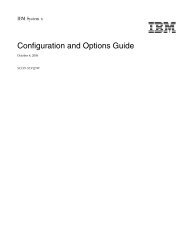
Server controls, LEDs, and connectorsThis section describes the controls, light-emitting diodes (LEDs), and connectors onthe front and rear of the server.FrontviewThe following illustration shows the controls and LEDs on the front of the server.Note: The front bezel door is not shown so that the drive bays are visible.<strong>System</strong> power LEDPower-control buttonHard disk drive activity LED<strong>System</strong> locator LED<strong>System</strong>-information LED<strong>System</strong>-error LEDDVD driveactivity LED(green)USB 2USB 1DVD-eject buttonHard diskdrive statusLED (amber)Hard diskdrive activityLED (green)<strong>System</strong> Power-on LED: When this LED is lit and not flashing, it indicates that theserver is turned on. When this LED is flashing, it indicates that the server is turnedoff and still connected to an ac power source. When this LED is off, it indicates thatac power is not present, or the power supply or the LED itself has failed. A powerLED is also on the rear of the server.Power-control button: Press this button to turn the server on and off manually. Apower-control-button shield comes with the server. You can install this disk-shapedshield to prevent the server from being turned off accidentally.Hard disk drive activity LED: When this LED is flashing, it indicates that a harddisk drive is in use.<strong>System</strong> locator LED: Use this LED to visually locate the server among otherservers. You can use <strong>IBM</strong> Director to light this LED remotely.4 <strong>IBM</strong> <strong>System</strong> <strong>x3500</strong> <strong>Type</strong> <strong>7977</strong>: <strong>Problem</strong> Determination and Service Guide
<strong>System</strong>-information LED: When this amber LED is on, the server power suppliesare nonredundant, or some other noncritical event has occurred. The event isrecorded in the error log. Check the light path diagnostic panel for more information(see the <strong>Problem</strong> Determination and Service Guide on the <strong>IBM</strong> <strong>System</strong> xDocumentation CD).<strong>System</strong>-error LED: When this amber LED is lit, it indicates that a system error hasoccurred. Use the diagnostic LED panel and the system service label on the insideof the left-side cover to further isolate the error. See the <strong>Problem</strong> Determination andService Guide on the <strong>IBM</strong> <strong>System</strong> x Documentation CD for additional information.USB 1: Connect a USB device to this connector.USB 2: Connect a USB device to this connector.DVD-eject button: Press this button to release a CD or DVD from the DVD drive.Hard disk drive status LED: When this LED is lit, it indicates that the associatedhard disk drive has failed. If an optional RAID adapter is installed in the server andthe LED flashes slowly (one flash per second), the drive is being rebuilt. If the LEDflashes rapidly (three flashes per second), the controller is identifying the drive.Hard disk drive activity LED: When this LED is flashing, it indicates that the driveis in use.Hard disk drive status LED: On some server models, each hot-swap hard diskdrive has a status LED. When this LED is lit, it indicates that the drive has failed. Ifan optional <strong>IBM</strong> ServeRAID controller is installed in the server, when this LED isflashing slowly (one flash per second), it indicates that the drive is being rebuilt.When the LED is flashing rapidly (three flashes per second), it indicates that thecontroller is identifying the drive.DVD drive activity LED: When this LED is lit, it indicates that the DVD drive is inuse.Chapter 1. Introduction 5
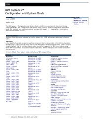
Rear viewThe following illustration shows the connectors and LEDs on the rear of the server.Power cordMouseKeyboardSerial 1(COM 1)ParallelVideoUSB 4Ethernet 10/100/1000USB 3Ethernet 10/100/1000RJ-45Serial 2(COM 2)Power-cord connector: Connect the power cord to this connector.Mouse connector: Connect a mouse or other PS/2 device to this connector.Keyboard connector: Connect a PS/2 keyboard to this connector.COM 1 connector: Connect a 9-pin serial device to this connector.Parallel connector: Connect a parallel device to this connector.Video connector: Connect a monitor to this connector.USB 3 connector: Connect a USB device to this connector.Ethernet connector: Use this connector to connect the server to a network.USB 4 connector: Connect a USB device to this connector.Ethernet connector: Use this connector to connect the server to a network.RJ-45 connector: Use this connector to connect the optional Remote SupervisorAdapter II SlimLine to a network.COM 2 connector: Connect a 9-pin serial device to this connector or using theConfiguration/Setup Utility program you can configure this port for use by the servermanagement.6 <strong>IBM</strong> <strong>System</strong> <strong>x3500</strong> <strong>Type</strong> <strong>7977</strong>: <strong>Problem</strong> Determination and Service Guide
Note: When this connector is configured for use with the server management, donot connect any other 9-pin serial devices to this connector.Chapter 1. Introduction 7
Internal LEDs, connectors, and jumpersThe illustrations in this section show the LEDs, connectors, and jumpers on theinternal boards. The illustrations might differ slightly from your hardware.<strong>System</strong>-board internal connectors and switchesThe following illustration shows the internal connectors on the system board.Power 1Internal USB tapePower 2Power 3DIMM 12DIMM 6 Power switchDIMM 11DIMM 5 DIMM 10DIMM 4DIMM 3DIMM 2DIMM 1Rear fan(optional)IDEDIMM 9DIMM 8DIMM 7Front USBMicroprocessor 1SAS 1 powerRemoteSupervisorAdapterPCI-E x8with x8 links slot 1PCI-E x8with x8 links slot 2PCI-E x8with x8 links slot 3PCI-X slot 4SAS 2 powerMicroprocessor 2SAS 1VRMSAS 2BatteryServeRAID-8kPCI-X slot 5PCI slot 6Wake-On-LAN Switch Block 3 (SW3)ReservedSee Table 2 for information about the switch settings.Wake-On-LAN(CN 45)Boot recovery (SW3)Table 2. Switches 1 - 8Switchnumber Default valueSwitchdescription8 Off Reserved.8 <strong>IBM</strong> <strong>System</strong> <strong>x3500</strong> <strong>Type</strong> <strong>7977</strong>: <strong>Problem</strong> Determination and Service Guide
Table 2. Switches 1 - 8 (continued)Switchnumber Default valueSwitchdescription7 Off Remote Supervisor Adapter II SlimLine BIST. When this switch is toggled to On, itcauses the Remote Supervisor Adapter II SlimLine to execute the Built In Self Test(BIST).6 Off Power-on override. When this switch is toggled to On, it forces the power on,overriding the power-on button.5 Off Power-on password override. Changing the position of this switch bypasses thepower-on password check the next time the server is turned on and starts theConfiguration/Setup Utility program so that you can change or delete the power-onpassword. You do not have to move the switch back to the default position after thepassword is overridden.Changing the position of this switch does not affect the administrator password checkif an administrator password is set.See the User’s Guide on the <strong>IBM</strong> <strong>System</strong> x Documentation CD for additionalinformation about the power-on password.4 Off Force BMC update. When this switch is toggled to On, it causes an update of BMCfirmware from the diskette drive.3 Off Force BMC reset. When this switch is toggled to On, it forces the BMC to reset.2 Off Reserved.1 Off Clear CMOS. When this switch is toggled to On, it clears the CMOS data, whichclears the power-on password.Notes:1. Before you change any switch settings or move any jumpers, turn off the server;then, disconnect all power cords and external cables. (Review the information in“Safety” on page vii, “Installation guidelines” on page 81, and “Handlingstatic-sensitive devices” on page 82.)2. Any system-board switch or jumper blocks that are not shown in the illustrationsin this document are reserved.Chapter 1. Introduction 9
<strong>System</strong>-boardLEDsThe following illustration shows the switches and LEDs on the system board.Microprocessor 1error LEDDIMMerror LEDs1 thru 12MicroprocessormismatchLEDSlot 1error LEDSlot 2error LEDSlot 3error LEDSlot 4error LEDSlot 5error LEDSlot 6error LEDMicroprocessor 2error LEDVRM errorLEDBattery error LEDBMC heartbeatLEDServeRAID-8kerror LED<strong>System</strong>-board external connectorsThe following illustration shows the external input/output connectors and the NMIswitch on the system board.MouseKeyboardSerial 1(COM 1)LPTVGAUSB 4RJ45USB 3RJ45NMISerial 2(COM 2)10 <strong>IBM</strong> <strong>System</strong> <strong>x3500</strong> <strong>Type</strong> <strong>7977</strong>: <strong>Problem</strong> Determination and Service Guide
SASbackplaneThe following illustration shows the connectors on the SAS backplane.Hard disk drive connectorsPower connectorSignal connectorChapter 1. Introduction 11
12 <strong>IBM</strong> <strong>System</strong> <strong>x3500</strong> <strong>Type</strong> <strong>7977</strong>: <strong>Problem</strong> Determination and Service Guide
Chapter 2. DiagnosticsThis chapter describes the diagnostic tools that are available to help you solveproblems that might occur in the server.If you cannot locate and correct the problem using the information in this chapter,see Appendix A, “Getting help and technical assistance,” on page 121 for moreinformation.DiagnostictoolsThe following tools are available to help you diagnose and solve hardware-relatedproblems:v POST beep codes, error messages, and error logsThe power-on self-test (POST) generates beep codes and messages to indicatesuccessful test completion or the detection of a problem. See “POST” for moreinformation.v Troubleshooting tablesThese tables list problem symptoms and actions to correct the problems. See“Troubleshooting tables” on page 30.v Light path diagnosticsUse the light path diagnostics to diagnose system errors quickly. See “Light pathdiagnostics” on page 43 for more information.v Diagnostic programs, messages, and error codesThe diagnostic programs are the primary method of testing the majorcomponents of the server. The diagnostic programs are on the <strong>IBM</strong> EnhancedDiagnostics CD that comes with the server. See “Diagnostic programs,messages, and error codes” on page 50 for more information.POSTWhen you turn on the server, it performs a series of tests to check the operation ofthe server components and some optional devices in the server. This series of testsis called the power-on self-test, or POST.If a power-on password is set, you must type the password and press Enter, whenprompted, for POST to run.If POST is completed without detecting any problems, a single beep sounds, andthe server startup is completed.If POST detects a problem, more than one beep might sound, or an error messageis displayed. See “Beep code descriptions” on page 14 and “POST error codes” onpage 19 for more information.POST beep codesA beep code is a combination of short or long beeps or series of short beeps thatare separated by pauses. For example, a “1-2-3” beep code is one short beep, apause, two short beeps, and pause, and three short beeps. A beep code other thanone beep indicates that POST has detected a problem. To determine the meaningof a beep code, see “Beep code descriptions” on page 14. If no beep code sounds,see “No-beep symptoms” on page 17.© Copyright <strong>IBM</strong> Corp. 2006 13
Beep code descriptionsThe following table describes the beep codes and suggested actions to correct thedetected problems.A single problem might cause more than one error message. When this occurs,correct the cause of the first error message. The other error messages usually willnot occur the next time POST runs.Exception: If there are multiple error codes or light path diagnostics LEDs thatindicate a microprocessor error, the error might be in a microprocessor or in amicroprocessor socket. See “Microprocessor problems” on page 36 for informationabout diagnosing microprocessor problems.v Follow the suggested actions in the order in which they are listed in the Action column until the problemis solved.v See Chapter 3, “Parts listing, <strong>Type</strong> <strong>7977</strong>,” on page 75 to determine which components are customerreplaceable units (CRU) and which components are field replaceable units (FRU).v If an action step is preceded by “(Trained service technician only),” that step must be performed only by atrained service technician.Beep code Description Action1-1-3 CMOS write/read test failed. 1. Reseat the following components:a. Batteryb. <strong>System</strong> board2. Replace the components listed in step 1one at a time, in the order shown, restartingthe server each time.1-1-4 BIOS ROM checksum failed. 1. Reseat the system board.2. (Trained service technician only) Replacethe sytstem board.1-2-1 Programmable interval timer failed. (Trained service technician only) Replace thesystem board.1-2-2 DMA initialization failed. (Trained service technician only) Replace thesystem board.1-2-3 DMA page register write/read failed. (Trained service technician only) Replace thesystem board.1-2-4 RAM refresh verification failed. 1. Reseat the DIMMs.2. Replace the following components, one at atime, in the order shown, restarting theserver each time:a. DIMMs1-3-1 1st 64K RAM test failed. 1. Reseat the DIMMs.b. (Trained service technician only) <strong>System</strong>board2. Replace the following components, one at atime, in the order shown, restarting theserver each time:a. DIMMsb. (Trained service technician only) <strong>System</strong>board2-1-1 Secondary DMA register failed. (Trained service technician only) Replace thesystem board.14 <strong>IBM</strong> <strong>System</strong> <strong>x3500</strong> <strong>Type</strong> <strong>7977</strong>: <strong>Problem</strong> Determination and Service Guide
v Follow the suggested actions in the order in which they are listed in the Action column until the problemis solved.v See Chapter 3, “Parts listing, <strong>Type</strong> <strong>7977</strong>,” on page 75 to determine which components are customerreplaceable units (CRU) and which components are field replaceable units (FRU).v If an action step is preceded by “(Trained service technician only),” that step must be performed only by atrained service technician.Beep code Description Action2-1-2 Primary DMA register failed. (Trained service technician only) Replace thesystem board.2-1-3 Primary interrupt mask register failed. (Trained service technician only) Replace thesystem board.2-1-4 Secondary interrupt mask register failed. (Trained service technician only) Replace thesystem board.2-4-1 Video failed; screen believed operable. (Trained service technician only) Replace thesystem board.3-1-1 Timer tick interrupt failed. (Trained service technician only) Replace thesystem board.3-1-2 Interval timer channel 2 failed. (Trained service technician only) Replace thesystem board.3-1-4 Time-of-day clock failed. 1. Reseat the following components:a. Batteryb. <strong>System</strong> board2. Replace the components listed in step 1one at a time, in the order shown, restartingthe server each time.3-3-2 Critical SMBUS error occurred. 1. Disconnect the power cord, wait 30seconds, and retry.2. Reseat the following components:a. DIMMb. <strong>System</strong> board3. Replace the following components one at atime, in the order shown, restarting theserver each time:a. DIMMb. (Trained service technician only) <strong>System</strong>board3-3-3 No operational memory in system. 1. Make sure that all DIMMs are the correctnumber of DIMMs; install or reseat DIMMS;then, restart the server.2. Reseat the following components:a. DIMMb. <strong>System</strong> board3. Replace the following components one at atime, in the order shown, restarting theserver each time:a. DIMMb. (Trained service technician only) <strong>System</strong>boardChapter 2. Diagnostics 15
v Follow the suggested actions in the order in which they are listed in the Action column until the problemis solved.v See Chapter 3, “Parts listing, <strong>Type</strong> <strong>7977</strong>,” on page 75 to determine which components are customerreplaceable units (CRU) and which components are field replaceable units (FRU).v If an action step is preceded by “(Trained service technician only),” that step must be performed only by atrained service technician.Beep code Description ActionTwo short beeps Information only, configuration haschanged.1. Run the Configuration/Setup Utility program.2. Run the diagnostic programs.One continuous beep Microprocessor error. 1. Reseat the following components:a. (Trained service technician only)Microprocessorb. (Trained service technician only)Optional microprocessorc. <strong>System</strong> board2. Replace the following components one at atime, in the order shown, restarting theserver each time.a. (Trained service technician only)Microprocessorb. (Trained service technician only)Optional microprocessorc. (Trained service technician only) <strong>System</strong>boardRepeating short beeps Keyboard error. 1. Reseat the following components:a. Keyboardb. <strong>System</strong> board2. Replace the components listed in step 1one at a time, in the order shown, restartingthe server each time.Repeating long beeps Memory error. 1. Reseat the following components:a. DIMMsb. <strong>System</strong> board2. Replace the following components one at atime, in the order shown, restarting theserver each time:a. DIMMb. (Trained service technician only) <strong>System</strong>board16 <strong>IBM</strong> <strong>System</strong> <strong>x3500</strong> <strong>Type</strong> <strong>7977</strong>: <strong>Problem</strong> Determination and Service Guide
No-beep symptomsThe following table describes situations in which no beep code sounds when POSTis completed.v Follow the suggested actions in the order in which they are listed in the Action column until the problemis solved.v See Chapter 3, “Parts listing, <strong>Type</strong> <strong>7977</strong>,” on page 75 to determine which components are customerreplaceable units (CRU) and which components are field replaceable units (FRU).v If an action step is preceded by “(Trained service technician only),” that step must be performed only by atrained service technician.No-beep symptom Description ActionNo beeps occur, and theserver operates correctly.No beeps occur aftersuccessful completion ofPOST.No beeps occur, andthere is no video.1. (Trained service technician only) Reseat theoperator information LED cable.2. (Trained service technician only) Replacethe operator information LED assembly.The power-on status is Disabled. 1. Run the Configuration/Setup Utility programand select Start Options; then, setPower-On Status to Enable.2. (Trained service technician only) Reseat theoperator information LED assembly.3. (Trained service technician only) Replacethe operator information LED assembly.See “Solving undetermined problems” on page72.ErrorlogsThe POST error log contains the three most recent error codes and messages thatwere generated during POST. The BMC log and the system-error log containmessages that were generated during POST and all system status messages fromthe service processor.The following illustration shows an example of a BMC log entry.BMC <strong>System</strong> Event Log----------------------------------------------------------Get Next EntryGet Previous EntryClear BMC SELEntry Number= 00005 / 00011Record ID= 0005Record <strong>Type</strong>= 02Timestamp= 2005/01/25 16:15:17Entry Details: Generator ID= 0020Sensor <strong>Type</strong>= 04Assertion EventFanThresholdLower Non-critical - going highSensor Number= 40Event Direction/<strong>Type</strong>= 01Event Data= 52 00 1AChapter 2. Diagnostics 17
The BMC log is limited in size. When the log is full, new entries will not overwriteexisting entries; therefore, you must periodically clear the BMC log through theConfiguration/Setup Utility program (the menu choices are described in the User’sGuide). When you are troubleshooting an error, be sure to clear the BMC log sothat you can find current errors more easily.Entries that are written to the BMC log during the early phase of POST show anincorrect date and time as the default time stamp; however, the date and time arecorrected as POST continues.Each BMC log entry appears on its own page. To display all the data for an entry,use the Up Arrow (↑) and Down Arrow (↓) keys or the Page Up and Page Downkeys. To move from one entry to the next, select Get Next Entry or Get PreviousEntry.The log indicates an assertion event when an event has occurred. It indicates adeassertion event when the event is no longer occurring.Some of the error codes and messages in the BMC log are abbreviated.If you view the BMC log through the Web interface of the optional RemoteSupervisor Adapter II SlimLine, the messages can be translated.You can view the contents of the POST error log, the BMC log, and thesystem-error log from the Configuration/Setup Utility program. You can view thecontents of the BMC log also from the diagnostic programs.When you are troubleshooting PCI-X slots, note that the error logs report the PCI-Xbuses numerically. The numerical assignments vary depending on the configuration.You can check the assignments by running the Configuration/Setup Utility program(see the User’s Guide for more information).Viewing error logs from the Configuration/Setup Utility programFor complete information about using the Configuration/Setup Utility program, seethe User’s Guide.To view the error logs, complete the following steps:1. Turn on the server.2. When the prompt Press F1 for Configuration/Setup appears, press F1. If youhave set both a power-on password and an administrator password, you musttype the administrator password to view the error logs.3. Use one of the following procedures:v To view the POST error log, select Error Logs, and then select POST ErrorLog.v To view the BMC log, select Advanced Settings, select BaseboardManagement Controller (BMC) settings, and then select BMC <strong>System</strong>Event Log.v To view the system-error log (available only if an optional Remote SupervisorAdapter II SlimLine is installed), select Event/Error Logs, and then select<strong>System</strong> Event/Error Log.Viewing the BMC log from the diagnostic programsThe BMC log contains the same information, whether it is viewed from theConfiguration/Setup Utility program or from the diagnostic programs.18 <strong>IBM</strong> <strong>System</strong> <strong>x3500</strong> <strong>Type</strong> <strong>7977</strong>: <strong>Problem</strong> Determination and Service Guide
For information about using the diagnostic programs, see “Running the diagnosticprograms” on page 50.To view the BMC log, complete the following steps:1. If the server is running, turn off the server and all attached devices.2. Turn on all attached devices; then, turn on the server.3. When the prompt F1 for Configuration/Setup appears, press F1.4. When the Configuration/Setup Utility menu appears, select Start Options.5. From the Start Options menu, select Startup Sequence Options.6. Note the device that is selected as the first startup device. Later, you mustrestore this setting.7. Select DVD-ROM as the first startup device.8. Press Esc two times to return to the Configuration/Setup Utility menu.9. Insert the <strong>IBM</strong> Enhanced Diagnostics CD in the CD drive.10. Select Save & Exit Setup and follow the prompts. The diagnostics will load.11. From the top of the screen, select Hardware Info.12. From the list, select BMC Log.POST error codesThe following table describes the POST error codes and suggested actions tocorrect the detected problems.v Follow the suggested actions in the order in which they are listed in the Action column until the problemis solved.v See Chapter 3, “Parts listing, <strong>Type</strong> <strong>7977</strong>,” on page 75 to determine which components are customerreplaceable units (CRU) and which components are field replaceable units (FRU).v If an action step is preceded by “(Trained service technician only),” that step must be performed only by atrained service technician.Error code Description Action062 Three consecutive boot failures using thedefault configuration.101 Tick timer internal interrupt, internal timerchannel 2.1. Flash the system firmware to the latest level (see“Updating the firmware” on page 111).2. Reseat the system board.3. Replace the system board.1. Reseat the system board.2. Replace the system board.102 Internal timer channel 2 test failure (Trained service technician only) Replace the systemboard.151 Real-time clock error. 1. Reseat the following components:a. Batteryb. <strong>System</strong> board2. Replace the components listed in step 1 one at atime, in the order shown, restarting the servereach time.Chapter 2. Diagnostics 19
v Follow the suggested actions in the order in which they are listed in the Action column until the problemis solved.v See Chapter 3, “Parts listing, <strong>Type</strong> <strong>7977</strong>,” on page 75 to determine which components are customerreplaceable units (CRU) and which components are field replaceable units (FRU).v If an action step is preceded by “(Trained service technician only),” that step must be performed only by atrained service technician.Error code Description Action161 Real-time clock battery error. 1. Reseat the following components:a. Batteryb. <strong>System</strong> board2. Replace the components listed in step 1 one at atime, in the order shown, restarting the servereach time.162 A device configuration has changed 1. Run the Configuration/Setup Utility program,select Load Default Settings, and save thesettings.2. Reseat the following components:a. Batteryb. Failing devicec. <strong>System</strong> board3. Replace the components listed in step 2 one at atime, in the order shown, restarting the servereach time.163 Real-time clock error. 1. Run the Configuration/Setup Utility program,select Load Default Settings, make sure that thedate and time are correct, and save the settings.175 Service processor flash code damaged ornot loaded.Note: In this case, the service processor isthe optional Remote Supervisor Adapter II.2. Reseat the following components:a. Batteryb. <strong>System</strong> board3. Replace the components listed in step 2 one at atime, in the order shown, restarting the servereach time.1. Update the Remote Supervisor Adapter IIfirmware (see the <strong>Problem</strong> Determination andService Guide on the <strong>IBM</strong> <strong>System</strong> xDocumentation CD).2. Replace the Remote Supervisor Adapter II.184 Power-on password damaged. 1. Run the Configuration/Setup Utility program,select Load Default Settings, and save thesettings.2. Reseat the following components:a. Batteryb. <strong>System</strong> board3. Replace the components listed in step 2 one at atime, in the order shown, restarting the servereach time.20 <strong>IBM</strong> <strong>System</strong> <strong>x3500</strong> <strong>Type</strong> <strong>7977</strong>: <strong>Problem</strong> Determination and Service Guide
v Follow the suggested actions in the order in which they are listed in the Action column until the problemis solved.v See Chapter 3, “Parts listing, <strong>Type</strong> <strong>7977</strong>,” on page 75 to determine which components are customerreplaceable units (CRU) and which components are field replaceable units (FRU).v If an action step is preceded by “(Trained service technician only),” that step must be performed only by atrained service technician.Error code Description Action187 VPD serial number not set. 1. Set the serial number by updating the BIOS codelevel (see “Updating the firmware” on page 111).2. Reseat the following components:a. <strong>System</strong> boardb. Optional Remote Supervisor Adapter IISlimLine3. Replace the components listed in step 2 one at atime, in the order shown, restarting the servereach time.188 Remote Supervisor Adapter II SlimLineEEPROM error189 An attempt was made to access the serverwith an incorrect password.196 Microprocessors do not have the same L2or L3 cache size.Replace the Remote Supervisor Adapter II SlimLine.Restart the server and enter the administratorpassword; then, run the Configuration/Setup Utilityprogram and change the power-on password.Install microprocessors with the same L2 or L3 cachesize.198 Microprocessors are not the same speed Install microprocessor of the same speed.289 A DIMM has been disabled by the user orby the system.1. If the DIMM was disabled by the user, run theConfiguration/Setup Utility program and enablethe DIMM.2. Make sure that the DIMM is installed correctly(see “Memory module” on page 91).3. Reseat the DIMM.4. Replace the DIMM.301, 303 Keyboard or keyboard controller error. 1. If you have installed a USB keyboard, run theConfiguration/Setup Utility program and enablekeyboardless operation to prevent the POST errormessage 301 from being displayed during startup.2. Reseat the following components:a. Keyboardb. <strong>System</strong> board3. Replace the components listed in step 2 one at atime, in the order shown, restarting the servereach time.1604 Machine type mismatch detected Make sure the vital product data (VPD), installedhardware, and BMC code level is correct for theservers machine type.Chapter 2. Diagnostics 21
v Follow the suggested actions in the order in which they are listed in the Action column until the problemis solved.v See Chapter 3, “Parts listing, <strong>Type</strong> <strong>7977</strong>,” on page 75 to determine which components are customerreplaceable units (CRU) and which components are field replaceable units (FRU).v If an action step is preceded by “(Trained service technician only),” that step must be performed only by atrained service technician.Error code Description Action1762 Fixed disk configuration error. 1. Run the Configuration/Setup Utility program andload the defaults.2. Reseat the following components:a. SAS cablesb. SAS hard disk drivec. <strong>System</strong> board3. Replace the components listed in step 2 one at atime, in the order shown, restarting the servereach time.178x Fixed disk error. 1. Reseat the hard disk drive cables.2. Replace the hard disk drive cables.3. Run the hard disk drive diagnostic tests.4. Reseat the following components:a. Optional ServeRAID -8i adapterb. Hard disk drivec. <strong>System</strong> board5. Replace the components listed in step 4 one at atime, in the order shown, restarting the servereach time.1800 Unavailable PCI hardware interrupt. 1. Run the Configuration/Setup Utility program andadjust the adapter settings.2. Remove each adapter one at a time, restartingthe server each time, until the problem is isolated.1962 A drive does not contain a valid boot sector. 1. Make sure that a bootable operating system isinstalled.2. Run the hard disk drive diagnostic tests.3. Reseat the following components:a. SAS driveb. SAS hard disk drive backplane cablec. <strong>System</strong> board4. Replace the components listed in step 3 one at atime, in the order shown, restarting the servereach time.22 <strong>IBM</strong> <strong>System</strong> <strong>x3500</strong> <strong>Type</strong> <strong>7977</strong>: <strong>Problem</strong> Determination and Service Guide
v Follow the suggested actions in the order in which they are listed in the Action column until the problemis solved.v See Chapter 3, “Parts listing, <strong>Type</strong> <strong>7977</strong>,” on page 75 to determine which components are customerreplaceable units (CRU) and which components are field replaceable units (FRU).v If an action step is preceded by “(Trained service technician only),” that step must be performed only by atrained service technician.Error code Description Action5962 IDE DVD drive configuration error. 1. Run the Configuration/Setup Utility program andload the default settings (see “Configuration/SetupUtility menu choices” on page 113).2. Reseat the following components:a. DVD drive cableb. DVD drivec. <strong>System</strong> board3. Replace the components listed in step 2 one at atime, in the order shown, restarting the servereach time.8603 Pointing-device error. 1. Reseat the following components:a. Pointing device0001295 ECC circuit check. 1. Reseat DIMMsb. <strong>System</strong> board2. Replace the components listed in step 1 one at atime, in the order shown, restarting the servereach time.2. Replace the components in step 1 one at a time,in the order shown, restarting the server eachtime.00012000 Processor machine check error. 1. Reseat the following components:00019501 Processor 1 is not functioning; checkprocessor LEDs.a. (Trained service technician only)Microprocessorb. <strong>System</strong> board2. Replace the following components one at a time,in the order shown, restarting the server eachtime:a. (Trained service technician only)Microprocessorb. (Trained service technician only) <strong>System</strong>board1. Reseat the following components:a. <strong>System</strong> boardb. (Trained service technician only)Microprocessor 12. Replace the following components one at a time,in the order shown, restarting the server eachtime:a. (Trained service technician only)Microprocessor 1b. (Trained service technician only) <strong>System</strong>boardChapter 2. Diagnostics 23
v Follow the suggested actions in the order in which they are listed in the Action column until the problemis solved.v See Chapter 3, “Parts listing, <strong>Type</strong> <strong>7977</strong>,” on page 75 to determine which components are customerreplaceable units (CRU) and which components are field replaceable units (FRU).v If an action step is preceded by “(Trained service technician only),” that step must be performed only by atrained service technician.Error code Description Action00019502 Processor 2 is not functioning; checkprocessor LEDs.1. Reseat the following components:a. <strong>System</strong> boardb. (Trained service technician only)Microprocessor 22. Replace the following components one at a time,in the order shown, restarting the server eachtime:a. (Trained service technician only)Microprocessor 2b. (Trained service technician only) <strong>System</strong>board00019701 Processor 1 failed BIST. 1. Reseat the following components:a. (Trained service technician only)Microprocessor 1b. <strong>System</strong> board2. Replace the following components one at a time,in the order shown, restarting the server eachtime:a. (Trained service technician only)Microprocessor 1b. (Trained service technician only) <strong>System</strong>board00019702 Processor 2 failed BIST. 1. Reseat the following components:a. (Trained service technician only)Microprocessor 2b. <strong>System</strong> board2. Replace the following components one at a time,in the order shown, restarting the server eachtime:a. (Trained service technician only)Microprocessor 2b. (Trained service technician only) <strong>System</strong>board24 <strong>IBM</strong> <strong>System</strong> <strong>x3500</strong> <strong>Type</strong> <strong>7977</strong>: <strong>Problem</strong> Determination and Service Guide
v Follow the suggested actions in the order in which they are listed in the Action column until the problemis solved.v See Chapter 3, “Parts listing, <strong>Type</strong> <strong>7977</strong>,” on page 75 to determine which components are customerreplaceable units (CRU) and which components are field replaceable units (FRU).v If an action step is preceded by “(Trained service technician only),” that step must be performed only by atrained service technician.Error code Description Action1801 A PCI adapter has requested memoryresources that are not available.1802 No more I/O space is available for a PCIadapter.1803 No more memory (above 1 MB for a PCIadapter).1804 No more memory (below 1 MB for a PCIadapter).1. Change the order of the adapters in the PCI-Xslots. Make sure that the boot device ispositioned early in the scan order (see the User’sGuide for information about the scan order).2. Make sure that the settings for the adapter and allother adapters in the Configuration/Setup Utilityprogram are correct. If the memory resourcesettings are not correct, change them.3. If all memory resources are being used, removean adapter to make memory available to theadapter. Disabling the BIOS on the adaptershould correct the error. See the documentationthat comes with the adapter.1. If the error code indicates a particular PCI orPCI-X slot or device, remove that device.2. If the error remains, reseat the followingcomponents:a. Each adapterb. (Trained service technician only) PCI-X board3. Replace the components listed in step 2 one at atime, in the order shown, restarting the servereach time.1. If the error code indicates a particular PCI orPCI-X slot or device, remove that device.2. Reseat the following components:a. Each adapterb. (Trained service technician only) PCI-X board3. Replace the components listed in step 2 one at atime, in the order shown, restarting the servereach time.1. Reseat the following components:a. Each adapterb. (Trained service technician only) PCI-X board2. Replace the components listed in step 1 one at atime, in the order shown, restarting the servereach time.1805 PCI option ROM checksum error. 1. Remove the failing adapter.2. Reseat the following components:a. Each adapterb. (Trained service technician only) PCI-X board3. Replace the components listed in step 2 one at atime, in the order shown, restarting the servereach time.Chapter 2. Diagnostics 25
v Follow the suggested actions in the order in which they are listed in the Action column until the problemis solved.v See Chapter 3, “Parts listing, <strong>Type</strong> <strong>7977</strong>,” on page 75 to determine which components are customerreplaceable units (CRU) and which components are field replaceable units (FRU).v If an action step is preceded by “(Trained service technician only),” that step must be performed only by atrained service technician.Error code Description Action1806 PCI built-in self-test failure. 1. If the error code indicates a particular PCI orPCI-X slot or device, remove that device.2. Reseat the following components:a. Each adapterb. (Trained service technician only, if thespecified board is a FRU) The board that isindicated in the error code. (See Chapter 3,“Parts listing, <strong>Type</strong> <strong>7977</strong>,” on page 75 todetermine CRU or FRU status.)3. Replace the components listed in step 2 one at atime, in the order shown above, restarting theserver each time.1807, 1808 General PCI error. 1. Make sure that no devices have been disabled inthe Configuration/Setup Utility program.2. Reseat the following components:a. Failing adapterNote: If an error LED is lit on the PCI-Xboard or on an adapter, reseat that adapterfirst; if no LEDs are lit, reseat each adapterone at a time, restarting the server each time,to isolate the failing adapter.b. (Trained service technician only) PCI-X board3. Replace the components listed in step 2 one at atime, in the order shown, restarting the servereach time.1810 PCI error. 1. Remove the adapters from the PCI or PCI-Xslots.2. Reseat the following components:a. Failing adapterNote: If an error LED is lit on the PCI-Xboard or on an adapter, reseat that adapterfirst; if no LEDs are lit, reseat each adapterone at a time, restarting the server each time,to isolate the failing adapter.b. (Trained service technician only) PCI-X board3. Replace the components listed in step 2 one at atime, in the order shown, restarting the servereach time.26 <strong>IBM</strong> <strong>System</strong> <strong>x3500</strong> <strong>Type</strong> <strong>7977</strong>: <strong>Problem</strong> Determination and Service Guide
v Follow the suggested actions in the order in which they are listed in the Action column until the problemis solved.v See Chapter 3, “Parts listing, <strong>Type</strong> <strong>7977</strong>,” on page 75 to determine which components are customerreplaceable units (CRU) and which components are field replaceable units (FRU).v If an action step is preceded by “(Trained service technician only),” that step must be performed only by atrained service technician.Error code Description Action01295085 ECC checking hardware test error. 1. Reseat the following components:a. (Trained service technician only)Microprocessorb. DIMMc. <strong>System</strong> board2. Replace the following components one at a time,in the order shown, restarting the server eachtime:a. (Trained service technician only)Microprocessorb. DIMMc. (Trained service technician only) <strong>System</strong>board01298001 No update data for processor 1. 1. Make sure that all microprocessors have thesame cache size (see “Configuration/Setup Utilitymenu choices” on page 113).2. Update the BIOS code again (see “Updating thefirmware” on page 111).3. (Trained service technician only) Reseatmicroprocessor 1.4. (Trained service technician only) Replacemicroprocessor 1.01298002 No update data for processor 2. 1. Make sure that all microprocessors have thesame cache size (see “Using theConfiguration/Setup Utility program” on page112).2. Update the BIOS code again (see “Updating thefirmware” on page 111).3. (Trained service technician only) Reseatmicroprocessor 2.4. (Trained service technician only) Replacemicroprocessor 2.01298101 Bad update data for processor 1. 1. Make sure that all microprocessors have thesame cache size (see “Configuration/Setup Utilitymenu choices” on page 113).2. Update the BIOS code again (see “Updating thefirmware” on page 111).3. (Trained service technician only) Reseatmicroprocessor 1.4. (Trained service technician only) Replacemicroprocessor 1.Chapter 2. Diagnostics 27
v Follow the suggested actions in the order in which they are listed in the Action column until the problemis solved.v See Chapter 3, “Parts listing, <strong>Type</strong> <strong>7977</strong>,” on page 75 to determine which components are customerreplaceable units (CRU) and which components are field replaceable units (FRU).v If an action step is preceded by “(Trained service technician only),” that step must be performed only by atrained service technician.Error code Description Action01298102 Bad update data for processor 2. 1. Make sure that all microprocessors have thesame cache size (see “Configuration/Setup Utilitymenu choices” on page 113).2. Update the BIOS code again (see “Updating thefirmware” on page 111).3. (Trained service technician only) Reseatmicroprocessor 2.4. (Trained service technician only) Replacemicroprocessor 2.0I298200 Processor speed mismatch. Make sure that all microprocessors have the samecache size (see “Using the Configuration/Setup Utilityprogram” on page 112).I9990301 Fixed disk sector error. 1. Reseat the following components:a. Hard disk driveb. SAS hard disk drive backplanec. <strong>System</strong> board2. Replace the components listed in step 1 one at atime, in the order shown, restarting the servereach time.I9990305 An operating system was not found. 1. Make sure that a bootable operating system isinstalled.2. Run the hard disk drive diagnostic tests.3. Reseat the following components:a. Hard disk driveb. SAS hard disk drive backplane and cablesc. DVD drive and cablesd. <strong>System</strong> board4. Replace the components listed in step 3 one at atime, in the order shown, restarting the servereach time.I9990650 AC power has been restored. 1. Check the power cables.2. Check for interruption of the power supply (see“Power-supply LEDs” on page 49).3. Reseat the following components:a. Power supplyb. (Trained service technician only) Powerbackplane4. Replace the components listed in step 3 one at atime, in the order shown, restarting the servereach time.28 <strong>IBM</strong> <strong>System</strong> <strong>x3500</strong> <strong>Type</strong> <strong>7977</strong>: <strong>Problem</strong> Determination and Service Guide
Checkout procedureThe checkout procedure is the sequence of tasks that you should follow todiagnose a problem in the server.About the checkout procedureBefore performing the checkout procedure for diagnosing hardware problems,review the following information:v Read the safety information that begins on page vii.v The diagnostic programs provide the primary methods of testing the majorcomponents of the server, such as the <strong>System</strong> board, Ethernet controller,keyboard, mouse (pointing device), serial ports, and hard disk drives. You canalso use them to test some external devices. If you are not sure whether aproblem is caused by the hardware or by the software, you can use thediagnostic programs to confirm that the hardware is working correctly.v When you run the diagnostic programs, a single problem might cause more thanone error message. When this happens, correct the cause of the first errormessage. The other error messages usually will not occur the next time you runthe diagnostic programs.Exception: If there are multiple error codes or light path diagnostics LEDs thatindicate a microprocessor error, the error might be in a microprocessor or in amicroprocessor socket. See “Microprocessor problems” on page 36 forinformation about diagnosing microprocessor problems.v Before running the diagnostic programs, you must determine whether the failingserver is part of a shared hard disk drive cluster (two or more servers sharingexternal storage devices). If it is part of a cluster, you can run all diagnosticprograms except the ones that test the storage unit (that is, a hard disk drive inthe storage unit) or the storage adapter that is attached to the storage unit. Thefailing server might be part of a cluster if any of the following conditions is true:– You have identified the failing server as part of a cluster (two or more serverssharing external storage devices).– One or more external storage units are attached to the failing server and atleast one of the attached storage units is also attached to another server orunidentifiable device.– One or more servers are located near the failing server.Important: If the server is part of a shared hard disk drive cluster, run one testat a time. Do not run any suite of tests, such as “quick” or “normal” tests,because this might enable the hard disk drive diagnostic tests.v If the server is halted and a POST error code is displayed, see “Error logs” onpage 17. If the server is halted and no error message is displayed, see“Troubleshooting tables” on page 30 and “Solving undetermined problems” onpage 72.v For information about power-supply problems, see “Solving power problems” onpage 71 and “Power-supply LEDs” on page 49.v For intermittent problems, check the error log; see “Error logs” on page 17 and“Diagnostic programs, messages, and error codes” on page 50.Performing the checkout procedureTo perform the checkout procedure, complete the following steps:1. Is the server part of a cluster?Chapter 2. Diagnostics 29
v No: Go to step 2.v Yes: Shut down all failing servers that are related to the cluster. Go to step 2.2. Complete the following steps:a. Turn off the server and all external devices.b. Check all cables and power cords.c. Set all display controls to the middle positions.d. Turn on all external devices.e. Turn on the server. If the server does not start, see “Troubleshooting tables”.f. Check the system-error LED on the operator information panel. If it isflashing, check the light path diagnostics LEDs (see “Light path diagnostics”on page 43).g. Check for the following results:v Successful completion of POST, indicated by a single beepv Successful completion of startup, indicated by a readable display of theoperating-system desktop3. Did a single beep sound and are there readable instructions on the main menu?v No: Find the failure symptom in “Troubleshooting tables”; if necessary, see“Solving undetermined problems” on page 72.v Yes: Run the diagnostic programs (see “Running the diagnostic programs” onpage 50).– If you receive an error, see “Diagnostic error codes” on page 52.– If the diagnostic programs were completed successfully and you stillsuspect a problem, see “Solving undetermined problems” on page 72.Important: If the server has a baseboard management controller, clear the BMClog and system-event log after you resolve the condition. This will turn off theinformation LED.Checkpoint codes (trained service technicians only)TroubleshootingA checkpoint code identifies the check that was occurring when the server stopped;it does not provide error codes or suggest replacement components. Checkpointcodes are shown on the checkpoint display. By using the checkpoint display, you donot have to wait for the video to initialize each time you restart the server.Only one type of checkpoint code is supported in your server: BIOS checkpointcodes. The BIOS checkpoint codes might change when the BIOS code is updated.To read the BIOS checkpoint codes you will need to install a PCI POST card in oneof the PCI slots.For a list of checkpoint codes for the <strong>IBM</strong> <strong>System</strong> <strong>x3500</strong> server, seehttp://www.ibm.com/pc/qtechinfo/MIGR-4ZKPPT.html.tablesUse the troubleshooting tables to find solutions to problems that have identifiablesymptoms.If you cannot find the problem in these tables, see “Running the diagnosticprograms” on page 50 for information about testing the server.30 <strong>IBM</strong> <strong>System</strong> <strong>x3500</strong> <strong>Type</strong> <strong>7977</strong>: <strong>Problem</strong> Determination and Service Guide
DVD drive problemsIf you have just added new software or a new optional device and the server is notworking, complete the following steps before using the troubleshooting tables:1. Check the light path diagnostics LEDs on the operator information panel (see“Light path diagnostics” on page 43).2. Remove the software or device that you just added.3. Run the diagnostic tests to determine whether the server is running correctly.4. Reinstall the new software or new device.v Follow the suggested actions in the order in which they are listed in the Action column until the problemis solved.v See Chapter 3, “Parts listing, <strong>Type</strong> <strong>7977</strong>,” on page 75 to determine which components are customerreplaceable units (CRU) and which components are field replaceable units (FRU).v If an action step is preceded by “(Trained service technician only),” that step must be performed only by atrained service technician.SymptomThe DVD drive is notrecognized.Action1. Make sure that:v The IDE channel to which the DVD drive is attached (primary or secondary)is enabled in the Configuration/Setup Utility program.v All cables and jumpers are installed correctly.v The correct device driver is installed for the DVD drive.2. Run the DVD drive diagnostic programs.3. Reseat the following components:a. DVD driveb. DVD drive cableA DVD is not working correctly. 1. Clean the DVD.c. <strong>System</strong> board4. Replace the components listed in step 3 one at a time, in the order shown,restarting the server each time.The DVD drive tray is notworking.2. Run the DVD drive diagnostic programs.3. Reseat the DVD drive.4. Replace the DVD drive.1. Make sure that the server is turned on.2. Insert the end of a straightened paper clip into the manual tray-releaseopening.3. Reseat the DVD drive.4. Replace the DVD drive.Chapter 2. Diagnostics 31
General problemsv Follow the suggested actions in the order in which they are listed in the Action column until the problemis solved.v See Chapter 3, “Parts listing, <strong>Type</strong> <strong>7977</strong>,” on page 75 to determine which components are customerreplaceable units (CRU) and which components are field replaceable units (FRU).v If an action step is preceded by “(Trained service technician only),” that step must be performed only by atrained service technician.SymptomA cover lock is broken, an LEDis not working, or a similarproblem has occurred.ActionIf the part is a CRU, replace it. If the part is a FRU, the part must be replaced by atrained service technician.Hard disk drive problemsv Follow the suggested actions in the order in which they are listed in the Action column until the problemis solved.v See Chapter 3, “Parts listing, <strong>Type</strong> <strong>7977</strong>,” on page 75 to determine which components are customerreplaceable units (CRU) and which components are field replaceable units (FRU).v If an action step is preceded by “(Trained service technician only),” that step must be performed only by atrained service technician.SymptomNot all drives are recognized bythe hard disk drive diagnostictests.The server stops respondingduring the hard disk drivediagnostic test.A hard disk drive was notdetected while the operatingsystem was being started.A hard disk drive passes thediagnostic Fixed Disk Test, butthe problem remains.ActionRemove the drive that is indicated by the diagnostic tests; then, run the hard diskdrive diagnostic tests again. If the remaining drives are recognized, replace thedrive that you removed with a new one.Remove the hard disk drive that was being tested when the server stoppedresponding, and run the diagnostic test again. If the hard disk drive diagnostic testruns successfully, replace the drive that you removed with a new one.Reseat all hard disk drives and cables; then, run the hard disk drive diagnostictests again.Run the diagnostic SCSI Fixed Disk Test (see “Running the diagnostic programs”on page 50).Note: This test is not available on servers that have RAID arrays or servers thathave SATA hard disk drives.32 <strong>IBM</strong> <strong>System</strong> <strong>x3500</strong> <strong>Type</strong> <strong>7977</strong>: <strong>Problem</strong> Determination and Service Guide
Intermittent problemsv Follow the suggested actions in the order in which they are listed in the Action column until the problemis solved.v See Chapter 3, “Parts listing, <strong>Type</strong> <strong>7977</strong>,” on page 75 to determine which components are customerreplaceable units (CRU) and which components are field replaceable units (FRU).v If an action step is preceded by “(Trained service technician only),” that step must be performed only by atrained service technician.SymptomA problem occurs onlyoccasionally and is difficult todiagnose.Action1. Make sure that:v All cables and cords are connected securely to the rear of the server andattached devices.v When the server is turned on, air is flowing from the fan grille. If there is noairflow, the fan is not working. This can cause the server to overheat andshut down.2. Check the system-error log or BMC log (see “Error logs” on page 17).Keyboard, mouse, or pointing-device problemsv Follow the suggested actions in the order in which they are listed in the Action column until the problemis solved.v See Chapter 3, “Parts listing, <strong>Type</strong> <strong>7977</strong>,” on page 75 to determine which components are customerreplaceable units (CRU) and which components are field replaceable units (FRU).v If an action step is preceded by “(Trained service technician only),” that step must be performed only by atrained service technician.SymptomAll or some keys on thekeyboard do not work.Action1. Make sure that:v The keyboard cable is securely connected.v If you are using a PS/2 keyboard, the keyboard and mouse cables are notreversed.v The server and the monitor are turned on.2. If you are using a USB keyboard, run the Configuration/Setup Utility programand enable keyboardless operation to prevent the 301 POST error messagefrom being displayed during startup.3. If you are using a USB keyboard and it is connected to a USB hub, disconnectthe keyboard from the hub and connect it directly to the server.4. Replace the following components one at a time, in the order shown, restartingthe server each time:a. Keyboardb. (Trained service technician only) <strong>System</strong> boardChapter 2. Diagnostics 33
v Follow the suggested actions in the order in which they are listed in the Action column until the problemis solved.v See Chapter 3, “Parts listing, <strong>Type</strong> <strong>7977</strong>,” on page 75 to determine which components are customerreplaceable units (CRU) and which components are field replaceable units (FRU).v If an action step is preceded by “(Trained service technician only),” that step must be performed only by atrained service technician.SymptomThe mouse or pointing devicedoes not work.Action1. Make sure that:v The mouse or pointing-device cable is securely connected to the server.v If you are using a PS/2 mouse or pointing device, the keyboard and mouseor pointing-device cables are not reversed.v The mouse or pointing-device device drivers are installed correctly.v The server and the monitor are turned on.v The mouse option is enabled in the Configuration/Setup Utility program.2. If you are using a USB mouse or pointing device and it is connected to a USBhub, disconnect the mouse or pointing device from the hub and connect itdirectly to the server.3. Replace the following components one at a time, in the order shown, restartingthe server each time:a. Mouse or pointing deviceb. (Trained service technician only) <strong>System</strong> board34 <strong>IBM</strong> <strong>System</strong> <strong>x3500</strong> <strong>Type</strong> <strong>7977</strong>: <strong>Problem</strong> Determination and Service Guide
Memory problemsv Follow the suggested actions in the order in which they are listed in the Action column until the problemis solved.v See Chapter 3, “Parts listing, <strong>Type</strong> <strong>7977</strong>,” on page 75 to determine which components are customerreplaceable units (CRU) and which components are field replaceable units (FRU).v If an action step is preceded by “(Trained service technician only),” that step must be performed only by atrained service technician.SymptomThe amount of system memorythat is displayed is less than theamount of installed physicalmemory.Multiple rows of DIMMs in abranch are identified as failing.Action1. Make sure that:v No error LEDs are lit on the operator information panel or on the DIMM.v Memory mirroring does not account for the discrepancy.v The memory modules are seated correctly.v You have installed the correct type of memory.v If you changed the memory, you updated the memory configuration in theConfiguration/Setup Utility program.v All banks of memory are enabled. The server might have automaticallydisabled a memory bank when it detected a problem, or a memory bankmight have been manually disabled.2. Check the POST error log for error message 289:v If a DIMM was disabled by a system-management interrupt (SMI), replacethe DIMM.v If a DIMM was disabled by the user or by POST, run the Configuration/SetupUtility program and enable the DIMM.3. Run memory diagnostics (see “Running the diagnostic programs” on page 50).4. Make sure that there is no memory mismatch when the server is at theminimum memory configuration (two 512 MB DIMMs; see the information aboutthe minimum required configuration on page 72).5. Add one pair of DIMMs at a time, making sure that the DIMMs in each pair arematching.6. Add one DIMM at a time, making sure that the DIMMs on each DIMM arematching.7. Reseat the DIMMs8. Replace the components in step 7 one at a time, in the order shown, restartingthe server each time.1. Reseat the DIMMs; then, restart the server.2. Replace the lowest-numbered DIMM pair of those that are identified; then,restart the server. Repeat as necessary.3. (Trained service technician only) Replace the system board.Chapter 2. Diagnostics 35
Microprocessor problemsv Follow the suggested actions in the order in which they are listed in the Action column until the problemis solved.v See Chapter 3, “Parts listing, <strong>Type</strong> <strong>7977</strong>,” on page 75 to determine which components are customerreplaceable units (CRU) and which components are field replaceable units (FRU).v If an action step is preceded by “(Trained service technician only),” that step must be performed only by atrained service technician.SymptomThe server emits a continuousbeep during POST, indicatingthat the startup (boot)microprocessor is not workingcorrectly.Action1. Correct any errors that are indicated by the light path diagnostics LEDs (see“Light path diagnostics” on page 43).2. Make sure that the server supports all the microprocessors and that themicroprocessors match in speed and cache size.3. (Trained service technician only) Make sure that microprocessor 1 is seatedcorrectly.4. Reseat the following components:a. (Trained service technician only) microprocessor 1b. <strong>System</strong> board5. (Trained service technician only) If there is no indication of whichmicroprocessor has failed, isolate the error by testing with one microprocessorat a time.6. Replace the following components one at a time, in the order shown, restartingthe server each time:a. (Trained service technician only) microprocessor 2b. VRM 2c. (Trained service technician only) <strong>System</strong> board7. (Trained service technician only) If there are multiple error codes or light pathdiagnostics LEDs that indicate a microprocessor error, reverse the locations oftwo microprocessors to determine whether the error is associated with amicroprocessor or with a microprocessor socket.v If the error is associated with a microprocessor, replace the microprocessor.v If the error is associated with a VRM, replace the VRM.v If the error is associated with a microprocessor socket, replace the systemboard.MonitorproblemsSome <strong>IBM</strong> monitors have their own self-tests. If you suspect a problem with yourmonitor, see the documentation that comes with the monitor for instructions fortesting and adjusting the monitor. If you cannot diagnose the problem, call forservice.36 <strong>IBM</strong> <strong>System</strong> <strong>x3500</strong> <strong>Type</strong> <strong>7977</strong>: <strong>Problem</strong> Determination and Service Guide
v Follow the suggested actions in the order in which they are listed in the Action column until the problemis solved.v See Chapter 3, “Parts listing, <strong>Type</strong> <strong>7977</strong>,” on page 75 to determine which components are customerreplaceable units (CRU) and which components are field replaceable units (FRU).v If an action step is preceded by “(Trained service technician only),” that step must be performed only by atrained service technician.SymptomActionTesting the monitor 1. Make sure that the monitor cables are firmly connected.2. Try using a different monitor on the server, or try using the monitor that is beingtested on a different server.3. Run the diagnostic programs. If the monitor passes the diagnostic programs,the problem might be a video device driver.4. Reseat the following components:a. Remote Supervisor Adapter II SlimLine (if one is present)b. <strong>System</strong> board5. Replace the components listed in step 4 one at a time, in the order shown,restarting the server each time.The screen is blank. 1. If the server is attached to a KVM switch, bypass the KVM switch to eliminate itas a possible cause of the problem: connect the monitor cable directly to thecorrect connector on the rear of the server.The monitor works when youturn on the server, but thescreen goes blank when youstart some applicationprograms.2. Make sure that:v The server is turned on. If there is no power to the server, see “Powerproblems” on page 40.v The monitor cables are connected correctly.v The monitor is turned on and the brightness and contrast controls areadjusted correctly.v No beep codes sound when the server is turned on.Important: In some memory configurations, the 3-3-3 beep code might soundduring POST, followed by a blank monitor screen. If this occurs and the BootFail Count option in the Start Options of the Configuration/Setup Utilityprogram is enabled, you must restart the server three times to reset theconfiguration settings to the default configuration (the memory connector orbank of connectors enabled).3. Make sure that the correct server is controlling the monitor, if applicable.4. See “Solving undetermined problems” on page 72.1. Make sure that:v The application program is not setting a display mode that is higher than thecapability of the monitor.v You installed the necessary device drivers for the application.2. Run video diagnostics (see “Running the diagnostic programs” on page 50).v If the server passes the video diagnostics, the video is good; see “Solvingundetermined problems” on page 72.v If the server fails the video diagnostics, reseat the <strong>System</strong> board.v (Trained service technician only) Replace the <strong>System</strong> board.Chapter 2. Diagnostics 37
v Follow the suggested actions in the order in which they are listed in the Action column until the problemis solved.v See Chapter 3, “Parts listing, <strong>Type</strong> <strong>7977</strong>,” on page 75 to determine which components are customerreplaceable units (CRU) and which components are field replaceable units (FRU).v If an action step is preceded by “(Trained service technician only),” that step must be performed only by atrained service technician.SymptomThe monitor has screen jitter, orthe screen image is wavy,unreadable, rolling, or distorted.Wrong characters appear on thescreen.Action1. If the monitor self-tests show that the monitor is working correctly, consider thelocation of the monitor. Magnetic fields around other devices (such astransformers, appliances, fluorescent lights, and other monitors) can causescreen jitter or wavy, unreadable, rolling, or distorted screen images. If thishappens, turn off the monitor.Attention: Moving a color monitor while it is turned on might cause screendiscoloration.Move the device and the monitor at least 305 mm (12 in.) apart, and turn onthe monitor.Notes:a. To prevent diskette drive read/write errors, make sure that the distancebetween the monitor and any external diskette drive is at least 76 mm (3in.).b. Non-<strong>IBM</strong> monitor cables might cause unpredictable problems.2. Reseat the following components:a. Monitorb. Remote Supervisor Adapter II SlimLine (if one is present)c. <strong>System</strong> board3. Replace the components listed in step 2 one at a time, in the order shown,restarting the server each time.1. If the wrong language is displayed, update the BIOS code with the correctlanguage (see “Updating the firmware” on page 111).2. Reseat the following components:a. Monitorb. <strong>System</strong> board3. Replace the components listed in step 2 one at a time, in the order shown,restarting the server each time.38 <strong>IBM</strong> <strong>System</strong> <strong>x3500</strong> <strong>Type</strong> <strong>7977</strong>: <strong>Problem</strong> Determination and Service Guide
Optional-device problemsv Follow the suggested actions in the order in which they are listed in the Action column until the problemis solved.v See Chapter 3, “Parts listing, <strong>Type</strong> <strong>7977</strong>,” on page 75 to determine which components are customerreplaceable units (CRU) and which components are field replaceable units (FRU).v If an action step is preceded by “(Trained service technician only),” that step must be performed only by atrained service technician.SymptomAn <strong>IBM</strong> optional device that wasjust installed does not work.An <strong>IBM</strong> optional device thatused to work does not worknow.Action1. Make sure that:v The device is designed for the server (see http://www.ibm.com/servers/eserver/serverproven/compat/us/).v You followed the installation instructions that came with the device and thedevice is installed correctly.v You have not loosened any other installed devices or cables.v You updated the configuration information in the Configuration/Setup Utilityprogram. Whenever memory or any other device is changed, you mustupdate the configuration.2. Reseat the device that you just installed.3. Replace the device that you just installed.1. Make sure that all of the hardware and cable connections for the device aresecure.2. If the device comes with test instructions, use those instructions to test thedevice.3. If the failing device is a SCSI device, make sure that:v The cables for all external SCSI devices are connected correctly.v The last device in each SCSI chain, or the end of the SCSI cable, isterminated correctly.v Any external SCSI device is turned on. You must turn on an external SCSIdevice before turning on the server.4. Reseat the failing device.5. Replace the failing device.Chapter 2. Diagnostics 39
Power problemsv Follow the suggested actions in the order in which they are listed in the Action column until the problemis solved.v See Chapter 3, “Parts listing, <strong>Type</strong> <strong>7977</strong>,” on page 75 to determine which components are customerreplaceable units (CRU) and which components are field replaceable units (FRU).v If an action step is preceded by “(Trained service technician only),” that step must be performed only by atrained service technician.SymptomThe power-control button doesnot work (the server does notstart).Note: The power-control buttonwill not function until 20seconds after the server hasbeen connected to ac power.Action1. Make sure that the power-control button is working correctly:a. Disconnect the server power cords.b. Reconnect the power cords.c. (Trained service technician only) Reseat the operator information panelcables, and then repeat steps 1a and 1b.v (Trained service technician only) If the server starts, reseat the operatorinformation panel. If the problem remains, replace the operatorinformation panel.2. Make sure that:v The power cords are correctly connected to the server and to a workingelectrical outlet.v The type of memory that is installed is correct.v The DIMM is fully seated.v The LEDs on the power supply do not indicate a problem.v The microprocessors are installed in the correct sequence.3. Reseat the following components:a. DIMMsb. (Trained service technician only) Power switch connectorc. (Trained service technician only) Power backplaned. <strong>System</strong> board4. Replace the components listed in step 3 one at a time, in the order shown,restarting the server each time.5. If you just installed an optional device, remove it, and restart the server. If theserver now starts, you might have installed more devices than the power supplysupports.6. See “Power-supply LEDs” on page 49.7. See “Solving undetermined problems” on page 72.The server does not turn off. 1. Determine whether you are using an Advanced Configuration and PowerInterface (ACPI) or a non-ACPI operating system. If you are using a non-ACPIoperating system, complete the following steps:The server unexpectedly shutsdown, and the LEDs on theoperator information panel arenot lit.a. Press Ctrl+Alt+Delete.b. Turn off the server by pressing the power-control button for 5 seconds.c. Restart the server.d. If the server fails POST and the power-control button does not work,disconnect the power cord for 20 seconds; then, reconnect the power cordand restart the server.2. If the problem remains or if you are using an ACPI-aware operating system,suspect the <strong>System</strong> board.See “Solving undetermined problems” on page 72.40 <strong>IBM</strong> <strong>System</strong> <strong>x3500</strong> <strong>Type</strong> <strong>7977</strong>: <strong>Problem</strong> Determination and Service Guide
Serial port problemsv Follow the suggested actions in the order in which they are listed in the Action column until the problemis solved.v See Chapter 3, “Parts listing, <strong>Type</strong> <strong>7977</strong>,” on page 75 to determine which components are customerreplaceable units (CRU) and which components are field replaceable units (FRU).v If an action step is preceded by “(Trained service technician only),” that step must be performed only by atrained service technician.SymptomThe number of serial ports thatare identified by the operatingsystem is less than the numberof installed serial ports.Action1. Make sure that:v Each port is assigned a unique address in the Configuration/Setup Utilityprogram and none of the serial ports is disabled.v The serial port adapter (if one is present) is seated correctly.2. Reseat the serial port adapter.3. Replace the serial port adapter.A serial device does not work. 1. Make sure that:v The device is compatible with the server.v The serial port is enabled and is assigned a unique address.v The device is connected to the correct connector (see “Checkpoint codes(trained service technicians only)” on page 30).2. Reseat the following components:a. Failing serial deviceb. Serial cablec. Remote Supervisor Adapter II SlimLine (if one is present)d. <strong>System</strong> board3. Replace the components listed in step 2 one at a time, in the order shown,restarting the server each time.ServerGuideproblemsv Follow the suggested actions in the order in which they are listed in the Action column until the problemis solved.v See Chapter 3, “Parts listing, <strong>Type</strong> <strong>7977</strong>,” on page 75 to determine which components are customerreplaceable units (CRU) and which components are field replaceable units (FRU).v If an action step is preceded by “(Trained service technician only),” that step must be performed only by atrained service technician.SymptomThe ServerGuide Setup andInstallation CD will not start.The ServeRAID Managerprogram cannot view allinstalled drives, or the operatingsystem cannot be installed.The operating-systeminstallation programcontinuously loops.Action1. Make sure that the server supports the ServerGuide program and has astartable (bootable) DVD drive.2. If the startup (boot) sequence settings have been changed, make sure that theDVD drive is first in the startup sequence.3. If more than one DVD drive is installed, make sure that only one drive is set asthe primary drive. Start the CD from the primary drive.1. Make sure that the hard disk drive is connected correctly.2. Make sure that the SAS hard disk drive cables are securely connected.Make more space available on the hard disk.Chapter 2. Diagnostics 41
v Follow the suggested actions in the order in which they are listed in the Action column until the problemis solved.v See Chapter 3, “Parts listing, <strong>Type</strong> <strong>7977</strong>,” on page 75 to determine which components are customerreplaceable units (CRU) and which components are field replaceable units (FRU).v If an action step is preceded by “(Trained service technician only),” that step must be performed only by atrained service technician.SymptomThe ServerGuide program willnot start the operating-systemCD.The operating system cannot beinstalled; the option is notavailable.ActionMake sure that the operating-system CD is supported by the ServerGuide program.See the ServerGuide Setup and Installation CD label for a list of supportedoperating-system versions.Make sure that the server supports the operating system. If it does, either nological drive is defined (SCSI RAID servers), or the ServerGuide <strong>System</strong> Partitionis not present. Run the ServerGuide program and make sure that setup iscomplete.Softwareproblemsv Follow the suggested actions in the order in which they are listed in the Action column until the problemis solved.v See Chapter 3, “Parts listing, <strong>Type</strong> <strong>7977</strong>,” on page 75 to determine which components are customerreplaceable units (CRU) and which components are field replaceable units (FRU).v If an action step is preceded by “(Trained service technician only),” that step must be performed only by atrained service technician.SymptomYou suspect a softwareproblem.Action1. To determine whether the problem is caused by the software, make sure that:v The server has the minimum memory that is needed to use the software. Formemory requirements, see the information that comes with the software. Ifyou have just installed an adapter or memory, the server might have amemory-address conflict.v The software is designed to operate on the server.v Other software works on the server.v The software works on another server.2. If you received any error messages when using the software, see theinformation that comes with the software for a description of the messages andsuggested solutions to the problem.3. Contact your place of purchase of the software.42 <strong>IBM</strong> <strong>System</strong> <strong>x3500</strong> <strong>Type</strong> <strong>7977</strong>: <strong>Problem</strong> Determination and Service Guide
Universal Serial Bus (USB) port problemsv Follow the suggested actions in the order in which they are listed in the Action column until the problemis solved.v See Chapter 3, “Parts listing, <strong>Type</strong> <strong>7977</strong>,” on page 75 to determine which components are customerreplaceable units (CRU) and which components are field replaceable units (FRU).v If an action step is preceded by “(Trained service technician only),” that step must be performed only by atrained service technician.SymptomActionA USB device does not work. 1. Run USB diagnostics (see “Running the diagnostic programs” on page 50).2. Make sure that:v The correct USB device driver is installed.v The operating system supports USB devices.v A standard PS/2 keyboard or mouse is not connected to the server. If it is, aUSB keyboard or mouse will not work during POST.3. Make sure that the USB configuration options are set correctly in theConfiguration/Setup Utility program menu (see the User’s Guide for moreinformation).4. If you are using a USB hub, disconnect the USB device from the hub andconnect it directly to the server.VideoproblemsSee “Monitor problems” on page 36.Light path diagnosticsLight path diagnostics is a system of LEDs on various external and internalcomponents of the server. When an error occurs, LEDs are lit throughout theserver. By viewing the LEDs in a particular order, you can often identify the sourceof the error.When LEDs are lit to indicate an error, they remain lit when the server is turned off,provided that the server is still connected to power and the power supply isoperating correctly.Before working inside the server to view light path diagnostics LEDs, read thesafety information that begins on page vii and “Handling static-sensitive devices” onpage 82.If an error occurs, view the light path diagnostics LEDs in the following order:1. Look at the informational LEDs on the front of the server.v If the information LED is lit, it indicates that information about a suboptimalcondition in the server is available in the BMC log or in the system-error log.v If the system-error LED is lit, it indicates that an error has occurred; go tostep 2 on page 44.The following illustration shows the information LEDs that show through thebezel.Chapter 2. Diagnostics 43
Power-onLED (green)<strong>System</strong>locatorLED (blue)<strong>System</strong> errorLED (amber)PowercontrolbuttonSCSI or IDEbus activityLED (green)<strong>System</strong>informationLED (amber)2. To view the light path diagnostics panel, press the release latch on the front ofthe operator information panel to the left; then, slide it forward. This reveals thelight path diagnostics panel. Lit LEDs on this panel indicate the type of error thathas occurred.The following illustration shows the light path diagnostics panel.1POWERSUPPLY2REMINDMEMORYCONFIGTEMPDASD/RAIDFANCPUS_ERRVRMPCIBUSSP BUSNMISEE INSIDE COVER FOR MORE SERVICE INFORMATIONLook at the system service label on the top of the server, which gives anoverview of internal components that correspond to the LEDs on the light pathdiagnostics panel. This information and the information in “Light path diagnosticsLEDs” on page 45 can often provide enough information to diagnose the error.3. Remove the server cover and look inside the server for lit LEDs. Certaincomponents inside the server have LEDs that will be lit to indicate the locationof a problem.The following illustration shows the LEDs on the <strong>System</strong> board.44 <strong>IBM</strong> <strong>System</strong> <strong>x3500</strong> <strong>Type</strong> <strong>7977</strong>: <strong>Problem</strong> Determination and Service Guide
Microprocessor 1error LEDDIMMerror LEDs1 thru 12MicroprocessormismatchLEDSlot 1error LEDSlot 2error LEDSlot 3error LEDSlot 4error LEDSlot 5error LEDSlot 6error LEDMicroprocessor 2error LEDVRM errorLEDBattery error LEDBMC heartbeatLEDServeRAID-8kerror LEDRemindbuttonYou can use the remind button on the light path diagnostics panel to put thesystem-error LED on the operator information panel into Remind mode. When youpress the remind button, you acknowledge the error but indicate that you will nottake immediate action. The system-error LED flashes while it is in Remind modeand stays in Remind mode until one of the following conditions occurs:v All known errors are corrected.v The server is restarted.v A new error occurs, causing the system-error LED to be lit again.Light path diagnostics LEDsThe following table describes the LEDs on the light path diagnostics panel andsuggested actions to correct the detected problems.Chapter 2. Diagnostics 45
v Follow the suggested actions in the order in which they are listed in the Action column until the problemis solved.v See Chapter 3, “Parts listing, <strong>Type</strong> <strong>7977</strong>,” on page 75to determine which components are customerreplaceable units (CRU) and which components are field replaceable units (FRU).v If an action step is preceded by “(Trained service technician only),” that step must be performed only by atrained service technician.Lit light pathdiagnostics LED withthe system-error orinformation LED alsolit Description ActionAll LEDs are off (thepower LED is lit; theinformation LED mightbe lit).POWER SUPPLY 1 Power supply 1 has failed or hasbeen removed; also see“Power-supply LEDs” on page 49.Note: In a redundant powerconfiguration, the dc power LED onone power supply might be off.POWER SUPPLY 2 Power supply 2 has failed or hasbeen removed; also see“Power-supply LEDs” on page 49.Note: In a redundant powerconfiguration, the dc power LED onone power supply might be off.No action is necessary.1. Reinstall the power supply 1.2. Check the individual power-supply LEDs.3. Reseat the following components:a. Power supplyb. (Trained service technician only) Powerbackplane4. Replace the components listed in step 3 one at atime, in the order shown, restarting the server eachtime.5. If a 240 V ac fault has occurred, remove ac powerbefore restoring dc power.1. Reinstall the power supply 2.2. Check the individual power-supply LEDs.3. Reseat the following components:a. Power supplyb. (Trained service technician only) Powerbackplane4. Replace the components listed in step 3 one at atime, in the order shown, restarting the server eachtime.5. If a 240 V ac fault has occurred, remove ac powerbefore restoring dc power.CONFIG Microprocessor configuration error. 1. Mismatched microprocessors, remove and installtwo microprocessor of the same cache size, type,and clock speed.TEMP A system temperature or componenthas exceeded specifications.Note: A fan LED might also be lit.2. Check the system error log for informationindicating incompatible components.1. See the BMC log or the system-error log (see“Error logs” on page 17) for the source of the fault.2. Make sure that the airflow in the server is notblocked.3. If a fan LED is lit, reseat the fan.4. Replace the fan for which the LED is lit.5. Make sure that the room is neither too hot nor toocold (see “Environment” in “Checkout procedure”on page 29).46 <strong>IBM</strong> <strong>System</strong> <strong>x3500</strong> <strong>Type</strong> <strong>7977</strong>: <strong>Problem</strong> Determination and Service Guide
v Follow the suggested actions in the order in which they are listed in the Action column until the problemis solved.v See Chapter 3, “Parts listing, <strong>Type</strong> <strong>7977</strong>,” on page 75to determine which components are customerreplaceable units (CRU) and which components are field replaceable units (FRU).v If an action step is preceded by “(Trained service technician only),” that step must be performed only by atrained service technician.Lit light pathdiagnostics LED withthe system-error orinformation LED alsolit Description ActionCPU A microprocessor has failed, ismissing, or has been incorrectlyinstalled.Note: (Trained service technicianonly) Make sure that themicroprocessors are installed in thecorrect sequence; see “<strong>System</strong>board and microprocessor” on page106.S_ERRReservedVRM A dc-dc regulator has failed or ismissing.Note: This error is for either theVRM or integrated VRD. If the VRDhas failed, the system board mustbe replaced by an trained servicetechnician.SERVICEPROCESSOR BUSThere is a fault in the RemoteSupervisor Adapter II SlimLine.1. Check the BMC log or the system-error log todetermine the reason for the lit LED.2. Find the failing, missing, or mismatchedmicroprocessor by checking the LEDs on thesystem board.3. Reseat the following components:a. (Trained service technician only) Failingmicroprocessorb. <strong>System</strong> board4. Replace the following components one at a time,in the order shown, restarting the server each time:a. (Trained service technician only) Failingmicroprocessorb. (Trained service technician only) <strong>System</strong> board1. Check the BMC log or the system-error log todetermine the reason for the lit LED (for a VRM).2. Find the failing or missing VRM by checking theLEDs on the system board.3. Install any missing VRMs.4. Reseat the following components:a. Failing VRMb. (Trained service technician only)Microprocessor associated with the VRMc. <strong>System</strong> board5. Replace the following components one at a time,in the order shown, restarting the server each time:a. Failing VRMb. (Trained service technician only)Microprocessor associated with the VRMc. (Trained service technician only) <strong>System</strong> board1. Reseat the Remote Supervisor Adapter II SlimLine.2. Update the firmware for the Remote SupervisorAdapter II SlimLine (see “Updating the firmware”on page 111).3. Replace the Remote Supervisor Adapter IISlimLine.Chapter 2. Diagnostics 47
v Follow the suggested actions in the order in which they are listed in the Action column until the problemis solved.v See Chapter 3, “Parts listing, <strong>Type</strong> <strong>7977</strong>,” on page 75to determine which components are customerreplaceable units (CRU) and which components are field replaceable units (FRU).v If an action step is preceded by “(Trained service technician only),” that step must be performed only by atrained service technician.Lit light pathdiagnostics LED withthe system-error orinformation LED alsolit Description ActionMEMORY Memory failure.Note: The error LED on the DIMMis also lit.DASD/RAID A hard disk drive, integrated SAScontroller, or integrated RAID errorhas occurred.Notes:1. The error LED on the failinghard disk drive is also lit.2. Check the BMC event log for aServeRAID-8k or RAID error.FAN A fan has failed or has beenremoved.Note: A failing fan can also causethe TEMP LED to be lit.1. Remove the DIMM that has the lit error LED; then,press the light path diagnostics button on theDIMM to identify the failed DIMM.2. Reseat the DIMM.3. Replace the following components one at a time,in the order shown, restarting the server each time:a. DIMMb. (Trained service technician only) <strong>System</strong> board1. Reinstall the removed drive.2. Reseat the following components:a. Failing hard disk driveb. SAS hard disk drive backplanec. SAS signal and power cablesd. <strong>System</strong> boarde. ServeRAID-8k3. Replace the components listed in step 2 one at atime, in the order shown, restarting the server eachtime.1. Reinstall the removed fan.2. If an individual fan LED is lit, replace the fan.3. Reseat the system board.4. (Trained service technician only) Replace thesystem board.PCI BUS A PCI adapter has failed. 1. See the BMC log or the system-error log (see“Error logs” on page 17).NMI A hardware error has been reportedto the operating system.Note: The PCI or MEM LED mightalso be lit.2. Reseat the following components:a. Failing adapterb. <strong>System</strong> board3. Replace the components listed in step 2 one at atime, in the order shown, restarting the server eachtime.1. See the BMC log and the system-error log (see“Error logs” on page 17).2. If the PCI LED is lit, follow the instructions for thatLED.3. If the MEM LED is lit, follow the instructions forthat LED.4. Restart the server.48 <strong>IBM</strong> <strong>System</strong> <strong>x3500</strong> <strong>Type</strong> <strong>7977</strong>: <strong>Problem</strong> Determination and Service Guide
Power-supply LEDsThe following minimum configuration is required for the DC LED on the powersupply to be lit:v Power supplyv Power backplanev Power cordThe following minimum configuration is required for the server to start:v One microprocessorv Two 512 MB DIMMs on the DIMMv One power supplyv Power backplanev Power cordv <strong>System</strong> board assemblyThe following illustration shows the locations of the power-supply LEDs.AC power LEDDC power LEDThe following table describes the problems that are indicated by variouscombinations of the power-supply LEDs and the power-on LED on the operatorinformation panel and suggested actions to correct the detected problems.Chapter 2. Diagnostics 49
v Follow the suggested actions in the order in which they are listed in the Action column until the problemis solved.v See Chapter 3, “Parts listing, <strong>Type</strong> <strong>7977</strong>,” on page 75 to determine which components are customerreplaceable units (CRU) and which components are field replaceable units (FRU).v If an action step is preceded by “(Trained service technician only),” that step must be performed only by atrained service technician.Power-supplyLEDsACDCOperatorinformationpanelpower-onLED Description ActionOff Off Off No power to theserver, or a problemwith the ac powersource.Lit Off Off DC source or powersupply powerproblem.Lit Lit Off Standby powerproblem.Lit Lit Flashing <strong>System</strong> power-onproblem.1. Check the ac power to the server.2. Make sure that the power cord is connected to afunctioning power source.3. Remove one power supply at a time.1. Make sure that the system board is connected to thepower backplane.2. Remove and replace one power supply at a time.3. View the system-error log (see “Error logs” on page17).1. View the system-error log (see “Error logs” on page17).2. Remove one power supply at a time.3. (Trained service technician only) Replace the powerbackplane.1. View the system-error log (see “Error logs” on page17).2. Press the power-control button on the operatorinformation panel.3. Remove the optional Remote Supervisor Adapter IISlimLine, and try to turn on the server.4. Reseat the system board.Lit Lit Lit The power is good. No action is necessary.5. (Trained service technician only) Replace the systemboard.Diagnostic programs, messages, and error codesThe diagnostic programs are the primary method of testing the major componentsof the server. As you run the diagnostic programs, text messages and error codesare displayed on the screen and are saved in the test log. A diagnostic textmessage or error code indicates that a problem has been detected; to determinewhat action you should take as a result of a message or error code, see the table in“Diagnostic error codes” on page 52.Running the diagnostic programsTo run the diagnostic programs, complete the following steps:1. If the server is running, turn off the server and all attached devices.2. Turn on all attached devices; then, turn on the server.3. When the prompt F1 for Configuration/Setup appears, press F1.50 <strong>IBM</strong> <strong>System</strong> <strong>x3500</strong> <strong>Type</strong> <strong>7977</strong>: <strong>Problem</strong> Determination and Service Guide
4. When the Configuration/Setup Utility menu appears, select Start Options.5. From the Start Options menu, select Startup Sequence Options.6. Note the device that is selected as the first startup device. Later, you mustrestore this setting.7. Select DVD-ROM as the first startup device.8. Press Esc two times to return to the Configuration/Setup Utility menu.9. Insert the <strong>IBM</strong> Enhanced Diagnostics CD in the CD drive.10. Select Save & Exit Setup and follow the prompts. The diagnostics will load.11. From the diagnostic programs screen, select the test that you want to run, andfollow the instructions on the screen.When you are diagnosing hard disk drives, select SCSI Attached Disk Testfor the most thorough test. Select Fixed Disk Test for any of the followingsituations:v You want to run a faster test.v The server contains RAID arrays not connected to the integrated SAScontroller.v The server contains SATA or IDE hard disk drives not connected to theintegrated SAS controller.To determine what action you should take as a result of a diagnostic text messageor error code, see the table in “Diagnostic error codes” on page 52.If the diagnostic programs do not detect any hardware errors but the problemremains during normal server operations, a software error might be the cause. Ifyou suspect a software problem, see the information that comes with your software.A single problem might cause more than one error message. When this happens,correct the cause of the first error message. The other error messages usually willnot occur the next time you run the diagnostic programs.Exception: If there are multiple error codes or light path diagnostics LEDs thatindicate a microprocessor error, the error might be in a microprocessor or in amicroprocessor socket. See “Microprocessor problems” on page 36 for informationabout diagnosing microprocessor problems.If the server stops during testing and you cannot continue, restart the server and tryrunning the diagnostic programs again. If the problem remains, replace thecomponent that was being tested when the server stopped.The keyboard and mouse (pointing device) tests assume that a keyboard andmouse are attached to the server. If no mouse is attached to the server, you cannotuse the Next Cat and Prev Cat buttons to select categories. All othermouse-selectable functions are available through function keys. You can use theregular keyboard test to test a USB keyboard, and you can use the regular mousetest to test a USB mouse. You can run the USB interface test only if no USBdevices are attached. The USB test will not run if a Remote Supervisor Adapter IISlimLine is installed.To view server configuration information (such as system configuration, memorycontents, interrupt request (IRQ) use, direct memory access (DMA) use, devicedrivers, and so on), select Hardware Info from the top of the screen.Chapter 2. Diagnostics 51
Diagnostic text messagesDiagnostic text messages are displayed while the tests are running. A diagnostictext message contains one of the following results:Passed: The test was completed without any errors.Failed: The test detected an error.User Aborted: You stopped the test before it was completed.Not Applicable: You attempted to test a device that is not present in the server.Aborted: The test could not proceed because of the server configuration.Warning: The test could not be run. There was no failure of the hardware that wasbeing tested, but there might be a hardware failure elsewhere, or another problemprevented the test from running; for example, there might be a configurationproblem, or the hardware might be missing or is not being recognized.The result is followed by an error code or other additional information about theerror.Viewing the test logTo view the summary test log when the tests are completed, select Utility from thetop of the screen and then select View Test Log. To view a detailed test log, pressTAB while viewing the summary test log. The test-log data is maintained only whileyou are running the diagnostic programs. When you exit from the diagnosticprograms, the test log is cleared.To save the test log to a file on a diskette or to the hard disk, click Save Log on thediagnostic programs screen and specify a location and name for the saved log file.Notes:1. The diskette drive must be attached when starting the server.2. To create and use a diskette, you must add an optional external diskette drive tothe server.3. To save the test log to a diskette, you must use a diskette that you haveformatted yourself; this function does not work with preformatted diskettes. If thediskette has sufficient space for the test log, the diskette can contain other data.Diagnostic error codesThe following table describes the error codes that the diagnostic programs mightgenerate and suggested actions to correct the detected problems.If the diagnostic programs generate error codes that are not listed in the table,make sure that the latest levels of BIOS, Remote Supervisor Adapter II SlimLine,and ServeRAID code are installed.In the error codes, x can be any numeral or letter. However, if the three-digitnumber in the central position of the code is 000, 195, or 197, do not replace aCRU or FRU. These numbers appearing in the central position of the code have thefollowing meanings:000 The server passed the test. Do not replace a CRU or FRU.52 <strong>IBM</strong> <strong>System</strong> <strong>x3500</strong> <strong>Type</strong> <strong>7977</strong>: <strong>Problem</strong> Determination and Service Guide
195 The Esc key was pressed to end the test. Do not replace a CRU or FRU.197 This is a warning error, but it does not indicate a hardware failure; do notreplace a CRU or FRU. Take the action that is indicated in the Actioncolumn, but do not replace a CRU or a FRU. See the description ofWarning in “Diagnostic text messages” on page 52 for more information.v Follow the suggested actions in the order in which they are listed in the Action column until the problemis solved.v See Chapter 3, “Parts listing, <strong>Type</strong> <strong>7977</strong>,” on page 75 to determine which components are customerreplaceable units (CRU) and which components are field replaceable units (FRU).v If an action step is preceded by “(Trained service technician only),” that step must be performed only by atrained service technician.Error code Description Action001-198-000 Test aborted. 1. Check the diagnostic logs for messages thatindicate the cause of the error, and take theindicated action.2. From the diagnostic programs, run Quick MemoryTest All Banks; then, if an error is detected, takethe indicated action.3. Reinstall and, if necessary, update the BIOS codeon the server; then, run the test again (see“Updating the firmware” on page 111).001-250-001 Failed system board ECC (Trained service technician only) Replace systemboard.001-292-000 Core system: failed/CMOS checksum failed. Load the BIOS default settings by using theConfiguration/Setup Utility program, and run the testagain (see “Configuration/Setup Utility menu choices”on page 113).005-xxx-000 Failed video test. 1. Reseat the video adapter, if one is installed.2. (Trained service technician only) Replace thesystem board.011-xxx-000 Failed COM1 serial port test. 1. Reseat the <strong>System</strong> board.2. Replace the <strong>System</strong> board.015-xxx-001 Failed USB test. 1. Reseat the <strong>System</strong> board.015-xxx-198 Remote Supervisor Adapter II SlimLineinstalled or USB device connected duringUSB test.2. Replace the <strong>System</strong> board.1. If a Remote Supervisor Adapter II SlimLine isinstalled as an option, remove it and run the testagain.2. Remove all USB devices and run the test again.3. Reseat the <strong>System</strong> board.4. Replace the <strong>System</strong> board.035-285-001 Adapter Communication Error 1. Update the RAID Controller firmware.2. Reseat, and if necessary replace the controller.035-286-001 Adapter CPU Test Error 1. Update the RAID Controller firmware.2. Reseat, and if necessary replace the controller.035-287-001 Adapter Local RAM Test Error 1. Update the RAID Controller firmware.2. Reseat, and if necessary replace the controller.Chapter 2. Diagnostics 53
v Follow the suggested actions in the order in which they are listed in the Action column until the problemis solved.v See Chapter 3, “Parts listing, <strong>Type</strong> <strong>7977</strong>,” on page 75 to determine which components are customerreplaceable units (CRU) and which components are field replaceable units (FRU).v If an action step is preceded by “(Trained service technician only),” that step must be performed only by atrained service technician.Error code Description Action035-288-001 Adapter NVSRAM Test Error 1. Update the RAID Controller firmware.2. Reseat, and if necessary replace the controller.035-289-001 Adapter Cache Test Error 1. Update the RAID Controller firmware.2. Reseat, and if necessary replace the controller.035-292-001 Adapter Parameter Set Error 1. Update the RAID Controller firmware.2. Reseat, and if necessary replace the controller.035-230-001 Battery Low Replace the battery module on the controller.035-231-001 Abnormal Battery Temperature or BatteryStatus Unknown089-xxx-00n Failed microprocessor or optionalmicroprocessor test.Note: n = APIC id of the microprocessor166-051-000 <strong>System</strong> Management: Failed. Unable tocommunicate with ASM. It may be busy.Run the test again.Replace the battery module on the controller.1. Reseat the following components:a. (Trained service technician only)Microprocessor 1b. <strong>System</strong> board2. Replace the following components one at a time,in the order shown, restarting the server eachtime.a. (Trained service technician only)Microprocessor 1b. (Trained service technician only) <strong>System</strong>board1. Update the firmware (BIOS, service processor,and diagnostics; see “Updating the firmware” onpage 111).2. Run the diagnostic test again.3. Correct other error conditions (including failedsystems-management tests and items that arelogged in the Remote Supervisor Adapter IISlimLine system-error log) and retry.4. Disconnect all server and option power cordsfrom the server, wait 30 seconds, reconnect thepower cords, and retry.5. Reseat the Remote Supervisor Adapter IISlimLine.6. Replace the Remote Supervisor Adapter IISlimLine.54 <strong>IBM</strong> <strong>System</strong> <strong>x3500</strong> <strong>Type</strong> <strong>7977</strong>: <strong>Problem</strong> Determination and Service Guide
v Follow the suggested actions in the order in which they are listed in the Action column until the problemis solved.v See Chapter 3, “Parts listing, <strong>Type</strong> <strong>7977</strong>,” on page 75 to determine which components are customerreplaceable units (CRU) and which components are field replaceable units (FRU).v If an action step is preceded by “(Trained service technician only),” that step must be performed only by atrained service technician.Error code Description Action166-060-000 <strong>System</strong> Management: Failed. Unable tocommunicate with ASM. It may be busy.Run the test again.166-070-000 <strong>System</strong> Management: Failed. Unable tocommunicate with ASM. It may be busy.Run the test again.166-198-000 BIOS cannot detect ASM. Reseat ASMadapter in correct slot; ASM restart failure.Unplug and cold boot server to reset ASM.1. Update the firmware (BIOS, service processor,and diagnostics; see “Updating the firmware” onpage 111).2. Run the diagnostic test again.3. Correct other error conditions (including failedsystems-management tests and items that arelogged in the Remote Supervisor Adapter IISlimLine system-error log) and retry.4. Disconnect all server and option power cordsfrom the server, wait 30 seconds, reconnect thepower cords, and retry.5. Reseat the Remote Supervisor Adapter IISlimLine.6. Replace the Remote Supervisor Adapter IISlimLine.1. Update the firmware (BIOS, service processor,and diagnostics; see “Updating the firmware” onpage 111).2. Run the diagnostic test again.3. Correct other error conditions (including failedsystems-management tests and items that arelogged in the Remote Supervisor Adapter IISlimLine system-error log) and retry.4. Disconnect all server and option power cordsfrom the server, wait 30 seconds, reconnect thepower cords, and retry.5. Reseat the Remote Supervisor Adapter IISlimLine.6. Replace the Remote Supervisor Adapter IISlimLine.1. Run the diagnostic test again.2. Correct other error conditions (including otherfailed systems-management tests and items thatare logged in the Remote Supervisor Adapter IISlimLine system-error log) and retry.3. Disconnect all server and option power cordsfrom the server, wait 30 seconds, reconnect thepower cords, and retry.4. Reseat the following components:a. Remote Supervisor Adapter II SlimLineb. <strong>System</strong> board5. Replace the components listed in step 4 one at atime, in the order shown, restarting the servereach time.Chapter 2. Diagnostics 55
v Follow the suggested actions in the order in which they are listed in the Action column until the problemis solved.v See Chapter 3, “Parts listing, <strong>Type</strong> <strong>7977</strong>,” on page 75 to determine which components are customerreplaceable units (CRU) and which components are field replaceable units (FRU).v If an action step is preceded by “(Trained service technician only),” that step must be performed only by atrained service technician.Error code Description Action166-201-000 ISMP indicates I2C errors on bus X. 1. Reseat the system board.2. Replace the system board.166-201-001 ISMP indicates I2C errors on bus P. 1. Reseat the following components:a. (Trained service technician only) Powerbackplaneb. <strong>System</strong> board2. Replace the following components one at a time,in the order shown, restarting the server eachtime:a. (Trained service technician only) Powerbackplaneb. <strong>System</strong> boardc. (Trained service technician only) <strong>System</strong>board166-201-002 ISMP indicates I2C errors on bus I. Reseat and, if necessary, replace the system board.166-201-003 ISMP indicates I2C errors on bus C. 1. Reseat the system board2. Replace the system board166-201-004 ISMP indicates I2C errors on bus M. 1. Reseat the following components:a. <strong>System</strong> boardb. DIMM2. Replace the following components one at a time,in the order shown, restarting the server eachtime:a. DIMMb. (Trained service technician only) <strong>System</strong>board166-201-005 ISMP indicates I2C errors on bus S. 1. Reseat the following components:a. SAS hard disk drive backplane cablesb. <strong>System</strong> board2. Replace the following components one at a time,in the order shown, restarting the server eachtime:a. SAS hard disk drive backplaneb. <strong>System</strong> board166-201-006 ISMP indicates I2C errors on bus O. 1. Reseat the following components:a. (Trained service technician only) Operatorinformation panelb. <strong>System</strong> board2. Replace the components listed in step 1 one at atime, in the order shown, restarting the servereach time.56 <strong>IBM</strong> <strong>System</strong> <strong>x3500</strong> <strong>Type</strong> <strong>7977</strong>: <strong>Problem</strong> Determination and Service Guide
v Follow the suggested actions in the order in which they are listed in the Action column until the problemis solved.v See Chapter 3, “Parts listing, <strong>Type</strong> <strong>7977</strong>,” on page 75 to determine which components are customerreplaceable units (CRU) and which components are field replaceable units (FRU).v If an action step is preceded by “(Trained service technician only),” that step must be performed only by atrained service technician.Error code Description Action166-201-007 ISMP indicates I2C errors on bus M0. 1. Reseat the following components:a. DIMMsb. <strong>System</strong> board2. Replace the following components one at a time,in the order shown, restarting the server eachtime:a. DIMMsb. (Trained service technician only) <strong>System</strong>board166-201-008 ISMP indicates I2C errors on bus M1. 1. Reseat the following components:a. Memory cardb. <strong>System</strong> board2. Replace the following components one at a time,in the order shown, restarting the server eachtime:a. Memory cardb. (Trained service technician only) <strong>System</strong>board166-260-000 ASM restart failure. 1. Disconnect all server and option power cordsfrom the server, wait 30 seconds, reconnect thepower cords, and retry.166-342-000 <strong>System</strong> management BIST indicates failedtests.166-400-000 ISMP Self Test Result failed tests: xxxwhere xxx=flash, ROM, or RAM.2. Reseat the Remote Supervisor Adapter IISlimLine.3. Replace the Remote Supervisor Adapter IISlimLine.1. Disconnect all server and option power cordsfrom the server, wait 30 seconds, reconnect thepower cords, and retry.2. Reseat the Remote Supervisor Adapter IISlimLine.3. Replace the Remote Supervisor Adapter IISlimLine.1. Disconnect all server and option power cordsfrom the server, wait 30 seconds, reconnect thepower cords, and retry.2. Update the BMC firmware (see “Updating thefirmware” on page 111).3. Reseat the <strong>System</strong> board.4. Replace the <strong>System</strong> board.Chapter 2. Diagnostics 57
v Follow the suggested actions in the order in which they are listed in the Action column until the problemis solved.v See Chapter 3, “Parts listing, <strong>Type</strong> <strong>7977</strong>,” on page 75 to determine which components are customerreplaceable units (CRU) and which components are field replaceable units (FRU).v If an action step is preceded by “(Trained service technician only),” that step must be performed only by atrained service technician.Error code Description Action166-400-100 DMC Self Test Result failed tests: xxx wherexxx=flash, ROM, or RAM.1. Disconnect all server and option power cordsfrom the server, wait 30 seconds, reconnect thepower cords, and retry.2. Update the BIOS code, BMC, service processor,and diagnostics firmware (see “Updating thefirmware” on page 111).180-197-000 SCSI ASPI driver not installed. 1. Remove the RAID adapter, if one is installed, andrun the test again.2. Reseat the following components:a. SAS hard disk drive backplane cablesb. <strong>System</strong> board3. Replace the following components one at a time,in the order shown, restarting the server eachtime:a. SAS hard disk drive backplaneb. (Trained service technician only) <strong>System</strong>board180-198-000 Test aborted. Check other error(s) in summary log for more details180-358-000 Ethernet failure. 1. Enable ethernet in <strong>System</strong> Setup2. Update ethernet firmware3. (Trained service technician only) <strong>System</strong> board180-361-003 Failed fan LED test. 1. Reseat the following components:a. Fanb. <strong>System</strong> board2. Replace the components listed in step 1 one at atime, in the order shown, restarting the servereach time.180-xxx-000 Diagnostics LED failure. Run the diagnostic LED test for the failing LED.180-xxx-001 Failed front LED panel test. 1. Reseat the following components:a. (Trained service technician only) Operatorinformation LED assembly cableb. <strong>System</strong> board2. Replace the following components one at a time,in the order shown, restarting the server eachtime:a. (Trained service technician only) Operatorinformation LED assembly cableb. <strong>System</strong> boardc. (Trained service technician only) <strong>System</strong>board58 <strong>IBM</strong> <strong>System</strong> <strong>x3500</strong> <strong>Type</strong> <strong>7977</strong>: <strong>Problem</strong> Determination and Service Guide
v Follow the suggested actions in the order in which they are listed in the Action column until the problemis solved.v See Chapter 3, “Parts listing, <strong>Type</strong> <strong>7977</strong>,” on page 75 to determine which components are customerreplaceable units (CRU) and which components are field replaceable units (FRU).v If an action step is preceded by “(Trained service technician only),” that step must be performed only by atrained service technician.Error code Description Action180-xxx-002 Failed diagnostics LED panel test. 1. Reseat the following components:a. (Trained service technician only) Operatorinformation panelb. <strong>System</strong> board2. Replace the following components one at a time,in the order shown, restarting the server eachtime:a. (Trained service technician only) Operatorinformation panelb. <strong>System</strong> boardc. (Trained service technician only) <strong>System</strong>board180-xxx-005 Failed SCSI backplane LED test. 1. Reseat the following components:a. SAS hard disk drive backplane cableb. <strong>System</strong> board2. Replace the following components one at a time,in the order shown, restarting the server eachtime:a. SAS hard disk drive backplane cableb. SAS hard disk drive backplanec. <strong>System</strong> boardd. (Trained service technician only) <strong>System</strong>board180-xxx-007 Failed power supply fan LED test. 1. Reseat the following components:a. Power supplyb. <strong>System</strong> board2. Replace the components listed in step 1 one at atime, in the order shown, restarting the servereach time.180-xxx-008 Failed I/O board LED test. 1. Reseat the system board.201-198-000 Memory Test Aborted: Could not run thetest; suspect <strong>System</strong> board error.201-198-00n Memory Test Aborted: Could not run thetest.Note: n = 1-9 (programming error).2. Replace the system board.1. Restart the server.2. Run the diagnostic test again.3. Reinstall the diagnostic programs (see “Updatingthe firmware” on page 111).4. (Trained service technician only) Replace thesystem board.1. Restart the server.2. Run the diagnostic test again.3. Reinstall the diagnostic programs (see “Updatingthe firmware” on page 111 “Updating thefirmware” on page 111).Chapter 2. Diagnostics 59
v Follow the suggested actions in the order in which they are listed in the Action column until the problemis solved.v See Chapter 3, “Parts listing, <strong>Type</strong> <strong>7977</strong>,” on page 75 to determine which components are customerreplaceable units (CRU) and which components are field replaceable units (FRU).v If an action step is preceded by “(Trained service technician only),” that step must be performed only by atrained service technician.Error code Description Action201-xxx-n99 Failed Memory TestNotes:1. n = 1-6 (DIMM pair)2. 99 = Both DIMMs in the pair failed202-xxx-00n Failed system cache test.Note: n = APIC id of the microprocessor1. Reseat the DIMM pair.2. Replace the DIMM pair.1. Reseat the following components:a. (Trained service technician only)Microprocessor nb. <strong>System</strong> board2. Replace the following components one at a time,in the order shown, restarting the server eachtime:a. (Trained service technician only)Microprocessor nb. (Trained service technician only) <strong>System</strong>board215-xxx-000 Failed DVD test. 1. Run the test again with a different DVD.217-xxx-000 Failed fixed disk test.Note: If RAID is configured, the fixed disknumber refers to the RAID logical array.217-xxx-001 Failed fixed disk test.Note: If RAID is configured, the fixed disknumber refers to the RAID logical array.217-xxx-002 Failed fixed disk test.Note: If RAID is configured, the fixed disknumber refers to the RAID logical array.217-xxx-003 Failed fixed disk test.Note: If RAID is configured, the fixed disknumber refers to the RAID logical array.217-xxx-004 Failed fixed disk test.Note: If RAID is configured, the fixed disknumber refers to the RAID logical array.217-xxx-005 Failed fixed disk test.Note: If RAID is configured, the fixed disknumber refers to the RAID logical array.2. Reseat the following components:a. DVD driveb. Front panel assembly3. Replace the following components one at a time,in the order shown, restarting the server eachtime:a. DVD driveb. (Trained service technician only) Front panelassembly1. Reseat hard disk drive 1.2. Replace hard disk drive 1.1. Reseat hard disk drive 2.2. Replace hard disk drive 2.1. Reseat hard disk drive 3.2. Replace hard disk drive 3.1. Reseat hard disk drive 4.2. Replace hard disk drive 4.1. Reseat hard disk drive 5.2. Replace hard disk drive 5.1. Reseat hard disk drive 6.2. Replace hard disk drive 6.60 <strong>IBM</strong> <strong>System</strong> <strong>x3500</strong> <strong>Type</strong> <strong>7977</strong>: <strong>Problem</strong> Determination and Service Guide
v Follow the suggested actions in the order in which they are listed in the Action column until the problemis solved.v See Chapter 3, “Parts listing, <strong>Type</strong> <strong>7977</strong>,” on page 75 to determine which components are customerreplaceable units (CRU) and which components are field replaceable units (FRU).v If an action step is preceded by “(Trained service technician only),” that step must be performed only by atrained service technician.Error code Description Action217-198-xxx Could not establish drive parameters. 1. Check the drive cables and terminators.301-xxx-000 Failed keyboard test.Note: After installing a USB keyboard, youmight have to use the Configuration/SetupUtility program to enable keyboardlessoperation and prevent the POST errormessage 301 from being displayed duringstartup.2. Reseat the hard disk drive.3. Replace the hard disk drive.1. Reseat the following components:a. Keyboardb. <strong>System</strong> board2. Replace the components listed in step 1 one at atime, in the order shown, restarting the servereach time.302-xxx-xxx Failed mouse test. 1. Reseat the following components:a. Mouseb. <strong>System</strong> board2. Replace the components listed in step 1 one at atime, in the order shown, restarting the servereach time.305-xxx-xxx Failed video monitor test. 1. Reseat the following components:405-xxx-000 Failed Ethernet test on controller on I/Oboard.a. Monitorb. <strong>System</strong> board2. Replace the components listed in step 1 one at atime, in the order shown, restarting the servereach time.1. Make sure that Ethernet is not disabled in theConfiguration/Setup Utility program and that thecode is at the latest level.2. Reseat the system board.3. Replace the system board.<strong>System</strong>-error log messagesA system-error log is generated only if a Remote Supervisor Adapter II SlimLine isinstalled. The system-error log can contain messages of three types:Information Information messages do not require action; they record significantsystem-level events, such as when the server is started.Warning Warning messages do not require immediate action; they indicatepossible problems, such as when the recommended maximumambient temperature is exceeded.Error Error messages might require action; they indicate system errors,such as when a fan is not detected.Each message contains date and time information, and it indicates the source ofthe message (POST/BIOS or the service processor).Chapter 2. Diagnostics 61
Note: The BMC log, which you can view through the Configuration/Setup Utilityprogram, also contains many information, warning, and error messages.In the following example, the system-error log message indicates that the serverwas turned on at the recorded time.- - - - - - - - - - - - - - - - - - - - - - - - - - - - - - -Date/Time: 2002/05/07 15:52:03DMI <strong>Type</strong>:Source: SERVPROCError Code: <strong>System</strong> Complex Powered UpError Code:Error Data:Error Data:- - - - - - - - - - - - - - - - - - - - - - - - - - - - - - - - - - - - - - -The following table describes the possible system-error log messages andsuggested actions to correct the detected problems.v Follow the suggested actions in the order in which they are listed in the Action column until the problemis solved.v See Chapter 3, “Parts listing, <strong>Type</strong> <strong>7977</strong>,” on page 75 to determine which components are customerreplaceable units (CRU) and which components are field replaceable units (FRU).v If an action step is preceded by “(Trained service technician only),” that step must be performed only by atrained service technician.<strong>System</strong>-error log message Action1.5V Calgary PLL Power Good Fault 1. Reseat the system board.1.5V Power Good Fault 1. Reseat the system board1.8V Calgary 1 HSSIB Power Good Fault 1. Reseat the system board.1.8V Calgary 2 HSSIB Power Good Fault 1. Reseat the system board.2. (Trained service technician only) Replace the PCI-X board.2. (Trained service technician only) Replace the PCI-X board.2. (Trained service technician only) Replace the PCI-X board.2. (Trained service technician only) Replace the PCI-X board.1.8V Fault 1. If the light path diagnostics VRM LED is lit, replace the failingVRM.2. Reseat the following components:a. <strong>System</strong> boardb. Power supply2.5V Calgary HSSIB Power Good Fault 1. Reseat the system board.2.5V Calgary PLL Power Good Fault 1. Reseat thes<strong>System</strong> board.c. Power backplane3. Replace the components listed in step 2 one at a time, in theorder shown, restarting the server each time.2. (Trained service technician only) Replace the PCI-X board.2. (Trained service technician only) Replace the PCI-X board.3.3V Power Good Fault 1. Reseat the Remote Supervisor Adapter II SlimLine, if one ispresent.2. Reseat the <strong>System</strong> board.3. (Trained service technician only) Replace the PCI-X board.62 <strong>IBM</strong> <strong>System</strong> <strong>x3500</strong> <strong>Type</strong> <strong>7977</strong>: <strong>Problem</strong> Determination and Service Guide
v Follow the suggested actions in the order in which they are listed in the Action column until the problemis solved.v See Chapter 3, “Parts listing, <strong>Type</strong> <strong>7977</strong>,” on page 75 to determine which components are customerreplaceable units (CRU) and which components are field replaceable units (FRU).v If an action step is preceded by “(Trained service technician only),” that step must be performed only by atrained service technician.<strong>System</strong>-error log message Action5V Aux Power Good Fault 1. Reseat the system board.2. (Trained service technician only) Disconnect the cable thatconnects the operator information LED assembly to the <strong>System</strong>board.3. Replace the system board.4. (Trained service technician only) Replace the PCI-X board.5V Power Good Fault Disconnect the monitor and all USB devices from the server; then:1. Reseat the system board.12V A Bus Fault 1. Reseat the system board.2. (Trained service technician only) Replace the PCI-X board.2. Replace the PCI-X board.3. (Trained service technician only) Replace the power backplane12V B Bus Fault 1. Reseat the following components:a. Disk drivesb. SAS hard disk drive backplane cables2. Replace the following components one at a time, in the ordershown, restarting the server each time:a. Disk drivesb. SAS hard disk drive backplanec. (Trained service technician only) Power backplaned. (Trained service technician only) PCI-X board12V C Bus Fault 1. Reseat the following components:a. Adaptersb. <strong>System</strong> board2. Replace the following components one at a time, in the ordershown, restarting the server each time:a. Adaptersb. (Trained service technician only) PCI-X boardc. (Trained service technician only) Power backplane12V D Bus Fault 1. Reseat the following components:a. <strong>System</strong> boardb. DIMMs2. Replace the following components one at a time, in the ordershown, restarting the server each time:a. DIMMsb. (Trained service technician only) Power backplanec. (Trained service technician only) <strong>System</strong> boardChapter 2. Diagnostics 63
v Follow the suggested actions in the order in which they are listed in the Action column until the problemis solved.v See Chapter 3, “Parts listing, <strong>Type</strong> <strong>7977</strong>,” on page 75 to determine which components are customerreplaceable units (CRU) and which components are field replaceable units (FRU).v If an action step is preceded by “(Trained service technician only),” that step must be performed only by atrained service technician.<strong>System</strong>-error log message Action12V E Bus Fault 1. Reseat the following components:a. <strong>System</strong> boardb. DIMMs2. Replace the following components one at a time, in the ordershown, restarting the server each time:a. DIMMsb. (Trained service technician only) Power backplanec. (Trained service technician only) <strong>System</strong> board12V Planar Fault 1. Reseat the system board.2. (Trained service technician only) Replace the power backplanecable.3. Replace the system board12V Power Good Fault 1. Reseat the system board.2. Reseat the DIMMs.Application Posted Alert to ASM Information onlyBackplane Power Good Fault 1. Reseat the system board.3. (Trained service technician only) Replace the power suppllydocking cable (see “Power supply docking cable” on page 97).4. (Trained service technician only) Replace the system board.2. Reseat the DIMMs.Board 2.5V Power Good Fault 1. Reseat the system board.3. (Trained service technician only) Replace the power suppllydocking cable (see “Power supply docking cable” on page 97).4. (Trained service technician only) Replace the system board.2. Replace the system board.Calgary Core 1.5V Power Good Fault 1. Reseat the system board.CEC Card Power Good Fault 1. Reseat the system board.CPU %d IERR detected, the system has beenrestarted2. (Trained service technician only) Replace the PCI-X board.2. (Trained service technician only) Replace the PCI-X board.Information only; if the message remains:1. (Trained service technician only) Reseat the microprocessors.2. Reseat the microprocessor VRMs, if any are present.3. (Trained service technician only) Replace the microprocessor.CPU %d IERR, the CPU has been disabled Information only; if the message remains:1. (Trained service technician only) Reseat the microprocessors.2. Reseat the microprocessor VRMs, if any are present.3. (Trained service technician only) Replace the microprocessor.64 <strong>IBM</strong> <strong>System</strong> <strong>x3500</strong> <strong>Type</strong> <strong>7977</strong>: <strong>Problem</strong> Determination and Service Guide
v Follow the suggested actions in the order in which they are listed in the Action column until the problemis solved.v See Chapter 3, “Parts listing, <strong>Type</strong> <strong>7977</strong>,” on page 75 to determine which components are customerreplaceable units (CRU) and which components are field replaceable units (FRU).v If an action step is preceded by “(Trained service technician only),” that step must be performed only by atrained service technician.<strong>System</strong>-error log message ActionCPU %d non-critical over temperature warning 1. Make sure that the fans have good airflow and are notobstructed.2. (Trained service technician only) Reseat the microprocessorheat sink.CPU %d non-recoverable over temperature fault 1. Make sure that the fans have good airflow and are notobstructed.2. (Trained service technician only) Reseat the microprocessorheat sink.CPU removal detected Informational only; if the message remains:1. (Trained service technician only) Reseat the microprocessors.2. Reseat the microprocessor VRMs, if any are present.CPU X Over Temperature 1. Check all fans and remove any obstacles from the path of theairflow.Ethernet Data Rate modified from to by user Ethernet Duplex setting modified from to by user 2. Make sure that the room temperature is within therecommended range.3. Make sure that the microprocessor heat sinks are correctlyseated.Information onlyInformation onlyEthernet interface by user Information onlyEthernet locally administered MAC addressmodified from x:x:x:x:x:xEthernet MTU setting modified from x to y byuser Information onlyInformation onlyFan X Failure (X of 1-8) 1. Make sure that nothing is blocking the fan.2. Check the physical connection and make sure that the fan iscorrectly seated.3. Replace fan X.Fan X not detected (X of 1-8) 1. Make sure that nothing is blocking the fan or power supply.2. Check the physical connection and make sure that the fan iscorrectly seated.3. Replace fan X.Front Panel is not plugged in 1. Make sure that the operator information panel cables arecorrectly connected (verify LED activity).2. Replace the operator information panel.Chapter 2. Diagnostics 65
v Follow the suggested actions in the order in which they are listed in the Action column until the problemis solved.v See Chapter 3, “Parts listing, <strong>Type</strong> <strong>7977</strong>,” on page 75 to determine which components are customerreplaceable units (CRU) and which components are field replaceable units (FRU).v If an action step is preceded by “(Trained service technician only),” that step must be performed only by atrained service technician.<strong>System</strong>-error log message ActionHard Drive X Fault 1. Run diagnostics.2. Reseat the following components:a. Hard disk driveb. SAS backplane3. Replace the components listed in step 2 one at a time, in theorder shown, restarting the server each time.Hard drive X removal detected Reseat hard disk drive X and restart the server.Hostname set to by user Information onlyHot plug card is not plugged in 1. Make sure that the PCI or PCI-X cables are correctlyconnected.2. Reseat the failing hot-plug cable or adapter.3. Replace the failing hot-plug cable or adapter.Hurricane SMI 1.2V Power Good Fault 1. Reseat the system board.2. Reseat the DIMMs.Hurricane Vtt MR 1.5V Power Good Fault 1. Reseat the system board.3. (Trained service technician only) Replace the system board.2. Reseat the DIMMs.Hvtt IB 1.8V Power Good Fault 1. Reseat the system board.3. (Trained service technician only) Replace the system board.2. Reseat the DIMMs.Hvtr IB 2.5V Power Good Fault 1. Reseat the system board.3. (Trained service technician only) Replace the system board.2. Reseat the DIMMs.IB MR Reg 1.8V Power Good Fault 1. Reseat the system board.3. (Trained service technician only) Replace the system board.2. Reseat the DIMMs.3. (Trained service technician only) Replace the system board.Invalid CPU configuration (Trained service technician only) Make sure that themicroprocessors have been installed in the correct order (see“<strong>System</strong> board and microprocessor” on page 106).Invalid Fan configuration Replace any missing or failed fans.IP address of default gateway modified fromx.x.x.xIP address of network interface modified fromx.x.x.xIP subnet mask of network interface modifiedfrom x.x.x.xInformation onlyInformation onlyInformation only66 <strong>IBM</strong> <strong>System</strong> <strong>x3500</strong> <strong>Type</strong> <strong>7977</strong>: <strong>Problem</strong> Determination and Service Guide
v Follow the suggested actions in the order in which they are listed in the Action column until the problemis solved.v See Chapter 3, “Parts listing, <strong>Type</strong> <strong>7977</strong>,” on page 75 to determine which components are customerreplaceable units (CRU) and which components are field replaceable units (FRU).v If an action step is preceded by “(Trained service technician only),” that step must be performed only by atrained service technician.<strong>System</strong>-error log message ActionLoader Watchdog Triggered 1. Reconfigure the loader watchdog timer to have a higher value(twice the normal operating-system boot time).2. Install the Remote Supervisor Adapter II SlimLine device driverfor the operating system.3. Disable the loader watchdog.Machine check asserted 1. Reseat the DIMM.Machine check asserted for Card or Link -SPINT4. Check the integrity of the installed operating system.5. Reinstall the operating system with the applicable devicedrivers.2. Replace the DIMM.1. Reseat the DIMM.2. Replace the DIMM.Memory Card x inserted Information only; if the message remains:1. Make sure that the DIMM lever is securely latched.2. Reseat the DIMM.Memory Card x removed Information only; if the message remains:1. Make sure that the DIMM lever is securely latched.2. Reseat the DIMM.Multiple fan failures Replace any missing or failed fans or power supplies.OS Watchdog Triggered 1. Reconfigure the operating-system watchdog timer to have ahigher value.2. Reinstall the Remote Supervisor Adapter II SlimLine devicedriver for the operating system.3. Disable the operating-system watchdog.4. Check the integrity of the installed operating system.5. Reinstall the operating system with applicable device drivers.PCI-X Card Power Good Fault 1. Reseat the Remote Supervisor Adapter II SlimLine, if one ispresent.2. Reseat the system board.3. Replace the system board.4. (Trained service technician only) Replace the PCI-X board.POST Watchdog Triggered 1. Reconfigure the POST watchdog timer to have a higher value(consistent with the time it takes to complete POST).2. Disable the POST watchdog.Power Good Fault detected by DIMM %d. 1. Reseat the DIMMs.2. Reseat the DIMMs.3. Reseat the system board.4. (Trained service technician only) Replace the power backplane.5. (Trained service technician only) Replace the system board.Chapter 2. Diagnostics 67
v Follow the suggested actions in the order in which they are listed in the Action column until the problemis solved.v See Chapter 3, “Parts listing, <strong>Type</strong> <strong>7977</strong>,” on page 75 to determine which components are customerreplaceable units (CRU) and which components are field replaceable units (FRU).v If an action step is preceded by “(Trained service technician only),” that step must be performed only by atrained service technician.<strong>System</strong>-error log message ActionPower Supply %d Temperature Warning 1. Make sure that the power-supply fans have good airflow andare not obstructed.2. Make sure that the room temperature is within therecommended range (see “Environment” in “Checkoutprocedure” on page 29).3. Replace the power supply.Power supply current exceeded max spec value 1. Install another power supply (if possible) and make sure thatthe ac power cords are correctly connected.2. Remove devices that consume an extraordinary amount ofpower.3. (Trained service technician only) Replace the power backplane.Power Supply X 12V Over Current Fault 1. Reseat the following components:a. Power supplyb. Power supply docking cable2. Replace the following components:a. Power supplyb. (Trained service technician only) <strong>System</strong> boardPower Supply X 12V Over Voltage Fault 1. Reseat the following components:a. Power supplyb. Power supply docking cable2. Replace the following components:a. Power supplyb. (Trained service technician only) <strong>System</strong> boardPower Supply X 12V Under Voltage Fault 1. Reseat the following components:a. Power supplyb. Power supply docking cable2. Replace the following components:a. Power supplyb. (Trained service technician only) <strong>System</strong> boardPower Supply X AC Power Removed 1. Connect the ac power cord to power supply X.2. Replace power supply X.Power Supply X Current Fault 1. Reseat the following components:a. Power supplyb. Power supply docking cable2. Replace the following components:a. Power supplyb. (Trained service technician only) <strong>System</strong> board68 <strong>IBM</strong> <strong>System</strong> <strong>x3500</strong> <strong>Type</strong> <strong>7977</strong>: <strong>Problem</strong> Determination and Service Guide
v Follow the suggested actions in the order in which they are listed in the Action column until the problemis solved.v See Chapter 3, “Parts listing, <strong>Type</strong> <strong>7977</strong>,” on page 75 to determine which components are customerreplaceable units (CRU) and which components are field replaceable units (FRU).v If an action step is preceded by “(Trained service technician only),” that step must be performed only by atrained service technician.<strong>System</strong>-error log message ActionPower Supply X DC Good Fault 1. If the system power present LED is lit, reduce the server to theminimum configuration (see “Solving undetermined problems”on page 72) and replace components one at a time to isolatethe fault.2. Reseat the following components:a. Power supplyb. Power supply docking cable3. Replace the following components:a. Power supplyPower Supply X Removed 1. Reseat power supply X.b. (Trained service technician only) <strong>System</strong> board2. Replace power supply X.3. (Trained service technician only) Replace the power backplane.Power Supply X Temperature Fault 1. Make sure that the fan air intake areas are clear and wellventilated.2. Make sure that all fans are installed and functioning.3. Reseat power supply X.4. Replace power supply X.QA Cache 1.8V Power Good Fault 1. Reseat the system board.2. (Trained service technician only) Reseat the microprocessors.3. Reseat the microprocessor VRMs, if any are present.QA Vcc PLL Power Good Fault 1. Reseat the system board.4. (Trained service technician only) Replace the system board.2. (Trained service technician only) Reseat the microprocessors.3. Reseat the microprocessor VRMs, if any are present.QB Cache Power Good Fault 1. Reseat the system board.4. (Trained service technician only) Replace the system board.2. (Trained service technician only) Reseat the microprocessors.3. Reseat the microprocessor VRMs, if any are present.QB Vcc PLL Power Good Fault 1. Reseat the system board.Remote Login Successful. Login ID: Information only4. (Trained service technician only) Replace the system board.2. (Trained service technician only) Reseat the microprocessors.3. Reseat the microprocessor VRMs, if any are present.4. (Trained service technician only) Replace the system board.Chapter 2. Diagnostics 69
v Follow the suggested actions in the order in which they are listed in the Action column until the problemis solved.v See Chapter 3, “Parts listing, <strong>Type</strong> <strong>7977</strong>,” on page 75 to determine which components are customerreplaceable units (CRU) and which components are field replaceable units (FRU).v If an action step is preceded by “(Trained service technician only),” that step must be performed only by atrained service technician.<strong>System</strong>-error log message ActionResetting system due to an unrecoverable error Check the following light path diagnostics LEDs for faults:1. Microprocessors2. DIMMs3. Memory card4. <strong>System</strong> boardSCSI 1.8V Power Good Fault 1. Reseat the system board.2. Replace the system board.Single fan failure Replace any missing or failed fans or power supplies.SMI reported a Machine Check on Memory Card= %d1. Reseat the DIMM.2. Replace the DIMM.Software NMI Make sure that the system software is operating correctly and doesnot conflict with other software; the system software has created asoftware NMI.<strong>System</strong> Approaching Maximum PowerConsumption1. Install another power supply (if possible) and make sure thatthe ac power cords are correctly connected.2. Remove devices that consume an extraordinary amount ofpower.3. (Trained service technician only) Replace the power backplane.<strong>System</strong> Boot Failed 1. Check the POST/BIOS boot checkpoint indicator and see theapplicable documentation. “Checkpoint codes (trained servicetechnicians only)” on page 30.<strong>System</strong> Complex Powered Down Information only<strong>System</strong> Complex Powered Up Information only<strong>System</strong>-error log full Clear the event log.<strong>System</strong> log 75% full Information only<strong>System</strong> Memory Error 1. Reseat the DIMMs.2. Make sure that the DIMMs are correctly connected and seatedand that they are functional.3. Attempt to start the server from the BIOS backup page.2. Replace the DIMMs.<strong>System</strong> Running Nonredundant Power 1. Install another power supply (if possible) and make sure thatthe ac power cords are correctly connected.User attempting to power/resetserver2. Remove devices that consume an extraordinary amount ofpower.3. (Trained service technician only) Replace the power backplane.Information onlyVideo 1.8V Power Good Fault 1. Reseat the system board.2. Replace the system board.70 <strong>IBM</strong> <strong>System</strong> <strong>x3500</strong> <strong>Type</strong> <strong>7977</strong>: <strong>Problem</strong> Determination and Service Guide
v Follow the suggested actions in the order in which they are listed in the Action column until the problemis solved.v See Chapter 3, “Parts listing, <strong>Type</strong> <strong>7977</strong>,” on page 75 to determine which components are customerreplaceable units (CRU) and which components are field replaceable units (FRU).v If an action step is preceded by “(Trained service technician only),” that step must be performed only by atrained service technician.<strong>System</strong>-error log message ActionVideo 2.5V Power Good Fault 1. Reseat the Remote Supervisor Adapter II SlimLine, if one ispresent.2. Reseat the system board.3. Replace the system board.Video Core 1.8V Power Good Fault 1. Reseat the system board.2. Replace the system board.VRM X Power Good Fault 1. Reseat VRM.2. Reseat the system board.3. Replace VRM.Vtt Power Good Fault 1. Reseat the system board.4. (Trained service technician only) Replace the system board.2. (Trained service technician only) Reseat the microprocessors.3. Reseat the microprocessor VRMs, if any are present.4. (Trained service technician only) Replace the system board.Solving power problemsPower problems can be difficult to solve. For example, a short circuit can existanywhere on any of the power distribution buses. Usually, a short circuit will causethe power subsystem to shut down because of an overcurrent condition. Todiagnose a power problem, use the following general procedure:1. Turn off the server and disconnect all ac power cords.2. Check for loose cables in the power subsystem. Also check for short circuits, forexample, if a loose screw is causing a short circuit on a circuit board.3. Remove the adapters and disconnect the cables and power cords to all internaland external devices until the server is at the minimum configuration that isrequired for the server to start (see “Solving undetermined problems” on page72 for the minimum configuration).4. Reconnect all ac power cords and turn on the server. If the server startssuccessfully, replace the adapters and devices one at a time until the problem isisolated.If the server does not start from the minimum configuration, replace the componentsin the minimum configuration one at a time until the problem is isolated.Solving Ethernet controller problemsThe method that you use to test the Ethernet controller depends on which operatingsystem you are using. See the operating-system documentation for informationabout Ethernet controllers, and see the Ethernet controller device-driver readme file.Try the following procedures:Chapter 2. Diagnostics 71
v Make sure that the correct device drivers, which come with the server, areinstalled and that they are at the latest level.v Make sure that the Ethernet cable is installed correctly.– The cable must be securely attached at all connections. If the cable isattached but the problem remains, try a different cable.– If the Ethernet controller is set to operate at 100 Mbps, you must useCategory 5 cabling.– If you directly connect two servers (without a hub), or if you are not using ahub with X ports, use a crossover cable. To determine whether a hub has anX port, check the port label. If the label contains an X, the hub has an X port.v Determine whether the hub supports auto-negotiation. If it does not, tryconfiguring the integrated Ethernet controller manually to match the speed andduplex mode of the hub.v Check the Ethernet controller LEDs on the rear panel of the server. These LEDsindicate whether there is a problem with the connector, cable, or hub.– The Ethernet link status LED is lit when the Ethernet controller receives a linkpulse from the hub. If the LED is off, there might be a defective connector orcable or a problem with the hub.– The Ethernet transmit/receive activity LED is lit when the Ethernet controllersends or receives data over the Ethernet network. If the Ethernettransmit/receive activity light is off, make sure that the hub and network areoperating and that the correct device drivers are installed.v Check the LAN activity LED on the rear of the server. The LAN activity LED is litwhen data is active on the Ethernet network. If the LAN activity LED is off, makesure that the hub and network are operating and that the correct device driversare installed.v Check for operating-system-specific causes of the problem.v Make sure that the device drivers on the client and server are using the sameprotocol.If the Ethernet controller still cannot connect to the network but the hardwareappears to be working, the network administrator must investigate other possiblecauses of the error.Solving undetermined problemsIf the diagnostic tests did not diagnose the failure or if the server is inoperative, usethe information in this section.If you suspect that a software problem is causing failures (continuous orintermittent), see “Software problems” on page 42.Damaged data in CMOS memory or damaged BIOS code can cause undeterminedproblems. To reset the CMOS data, use the password override jumper to overridethe power-on password and clear the CMOS memory; see “Internal LEDs,connectors, and jumpers” on page 8.Check the LEDs on all the power supplies (see “Power-supply LEDs” on page 49).If the LEDs indicate that the power supplies are working correctly, complete thefollowing steps:1. Turn off the server.2. Make sure that the server is cabled correctly.3. Remove or disconnect the following devices, one at a time, until you find thefailure. Turn on the server and reconfigure it each time.v Any external devices.v Surge-suppressor device (on the server).72 <strong>IBM</strong> <strong>System</strong> <strong>x3500</strong> <strong>Type</strong> <strong>7977</strong>: <strong>Problem</strong> Determination and Service Guide
Calling <strong>IBM</strong> for servicev Modem, printer, mouse, and non-<strong>IBM</strong> devices.v Each adapter.v Hard disk drives.v Memory modules. The minimum configuration requirement is 1 GB (two 512MB DIMMs).v Service processor.The following minimum configuration is required for the server to start:v One microprocessorv Two 512 MB DIMMsv One power supplyv Power cord4. Turn on the server. If the problem remains, suspect the following components inthe following order:a. Power backplaneb. Memoryc. Microprocessord. <strong>System</strong> boardIf the problem is solved when you remove an adapter from the server but theproblem recurs when you reinstall the same adapter, suspect the adapter; if theproblem recurs when you replace the adapter with a different one, suspect thePCI-X board.If you suspect a networking problem and the server passes all the system tests,suspect a network cabling problem that is external to the server.See Chapter 5, “Configuration information and instructions,” on page 111 forinformation about calling <strong>IBM</strong> for service.When you call for service, have as much of the following information available aspossible:v Machine type and modelv Microprocessor and hard disk drive upgradesv Failure symptoms– Does the server fail the diagnostic programs? If so, what are the error codes?– What occurs? When? Where?– Is the failure repeatable?– Has the current server configuration ever worked?– What changes, if any, were made before it failed?– Is this the original reported failure, or has this failure been reported before?v Diagnostic program type and version levelv Hardware configuration (print screen of the system summary)v BIOS code levelv Operating-system type and version levelYou can solve some problems by comparing the configuration and software setupsbetween working and nonworking servers. When you compare servers to eachother for diagnostic purposes, consider them identical only if all the following factorsare exactly the same in all the servers:Chapter 2. Diagnostics 73
v Machine type and modelv BIOS levelv Adapters and attachments, in the same locationsv Address jumpers, terminators, and cablingv Software versions and levelsv Diagnostic program type and version levelv Configuration option settingsv Operating-system control-file setup74 <strong>IBM</strong> <strong>System</strong> <strong>x3500</strong> <strong>Type</strong> <strong>7977</strong>: <strong>Problem</strong> Determination and Service Guide
Chapter 3. Parts listing, <strong>Type</strong> <strong>7977</strong>The following parts information is for the <strong>IBM</strong> <strong>System</strong> <strong>x3500</strong>, <strong>Type</strong> <strong>7977</strong>.1262242532341921202251891312111087614151617© Copyright <strong>IBM</strong> Corp. 2006 75
Server replaceable unitsNotes:Table 3. Parts listing, <strong>Type</strong> <strong>7977</strong>IndexDescription1. Field replaceable units (FRUs) must be serviced only by trained servicetechnicians.2. Customer replaceable units (CRUs) can be replaced by the customer. Tier 1CRUs and Tier 2 CRUs are described in the <strong>IBM</strong> “Statement of LimitedWarranty” (at “Part 3 - Warranty Information”), which is in the Warranty andSupport Information document on the <strong>IBM</strong> Documentation CD.CRU No.(Tier 1)1 Power supply, 835 W 24R27312 Operator information panel assembly, with bracket andcables3 USM mounting bracket 39Y83554 Power backplane 41Y90685 DVD-ROM (primary) 39M35695 DVD-ROM (option) 39M35175 DVD-ROM (option) 39M35155 DVD-ROM, half-high (option) 42C09515 CD/RW/DVD combo drive (option) 39M35395 CD-ROM, 48X (option) 39M35115 CD-ROM, 48X (option) 39M35095 DVD-ROM (option) 39M35196 Half-high CD-ROM (option) 42C09536 Half-high combo drive (option) 39M01355 Half-high DVD-ROM (option) 42C09516 Hard disk drive, 73 GB, 10K, SAS, HS (option) 39R73406 Hard disk drive, 146 GB, 10K, SAS, HS (option) 39R73426 Hard disk drive, 73 GB, 15K, SAS, HS (option) 39R73486 Hard disk drive, 146 GB, 15K, SAS, HS (option) 39R73506 Hard disk drive, 80 GB (option) 39M45216 Hard disk drive, 160 GB (option) 39M45256 Hard disk drive, 250 GB (option) 39M45296 Hard disk drive, 300 GB (option) 39R73447 Bezel 41Y90448 Hard disk drive filler 41Y9043CRU No.(Tier 2) FRU No.41Y90809 SAS hard disk drive backplane 39Y975710 Fan Cage, front 41Y906711 Fan (120 X 38mm) 41Y902812 Microprocessor duct 39Y850113 <strong>System</strong> board with tray 42C154913 Tray, system board 41Y907776 <strong>IBM</strong> <strong>System</strong> <strong>x3500</strong> <strong>Type</strong> <strong>7977</strong>: <strong>Problem</strong> Determination and Service Guide
Table 3. Parts listing, <strong>Type</strong> <strong>7977</strong> (continued)Index DescriptionCRU No.(Tier 1)CRU No.(Tier 2) FRU No.14 ServeRAID-8k with battery pack 25R807615 Power supply VRM 24R269416 Light Path Diagnostic panel assembly 39Y712517 Left-side cover 39Y836018 Microprocessor baffle 39M680019 Heat sink 39M679120 Microprocessor, 1.6 GHZ (model 42x) 41Y427520 Microprocessor, 1.87 GHZ (model 52x) 41Y427620 Microprocessor, 2.0 GHZ (model 62) 41Y427720 Microprocessor, 2.33 GHZ (model 72x) 41Y427820 Microprocessor, 2.67 GHZ (model 82x) 41Y427920 Microprocessor, 3.0 GHZ (model 92x) 41Y428020 Microprocessor, 3.0 GHZ (model 12x) 41Y890520 Microprocessor, 3.2 GHZ (model 22x) 41Y422321 Retention module, microprocessor 39M678322 Memory, 512 MB PC5300 ECC 39M578122 Memory, 1 GB PC5300 ECC (option) 39M578422 Memory, 1 GB PC5300 ECC (option) 39M579022 Memory, 4 GB PC5300 ECC (option) 39M579623 Bracket holders (option) 41Y908624 DIMM air duct 39Y849925 Power supply cage 24R273826 Filler panel, power supply 24R2735Alcohol wipe 59P4739Adapter, NetXtreme1000 (option) 39Y6081Adapter, NetXtreme SXG (option) 39Y6090Adapter, NetXtreme dual (option) 39Y6095Adapter, NetXtreme TXG (option) 39Y6100Adapter, iSCSI TX server (option) 30R5209Adapter, iSCSI SX server (option) 30R5509Adapter, SCSI (option) 39R8750Chassis41Y9084Battery, 3.0 volt 33F8354Battery pack, ServeRAID-8k, 3.0 volt 25R8088Cable, DVD signal, IDE 13N2466Cable, diskette drive Interposer 39R9343Cable, fan harness 39Y8341Cable, front panel USB 26K7340Cable management arm 25R5238Chapter 3. Parts listing, <strong>Type</strong> <strong>7977</strong> 77
Table 3. Parts listing, <strong>Type</strong> <strong>7977</strong> (continued)Index DescriptionCRU No.(Tier 1)CRU No.(Tier 2) FRU No.Cable, power supply interposer 39Y8356Cable, rear 120x38 fans 39Y8400Cable, redundant rear 120x38 fans 39Y8401Cable, SAS power 39Y8508Cable, SAS signal 41Y9085Cable, second serial port 42C1053Cover button 41Y9069DD S/5 drive (option) 40K2553Drive bay filler 39M6800Fan air duct, rear 39Y8504Fan cage, rear 41Y9067Feet, stabilizer, front 26K7345Filler bezel assembly (option) 41Y9071Foot, system 13N2985Handy-vac CPU removal tool 26K7189Keylock26K7363Keylock26K7364Miscellaneous kit 41Y9079Mouse39Y9872Mouse, 3B USB optical (option) 40K9203PRO/1000 GT server ethernet adapter, DP (option) 73P5109PRO/1000 GT server ethernet adapter, QP (option) 73P5209Rack bezel assembly (option) 41Y9072Remote supervisory adapter 2 13N0833Shield, system board I/O 41Y9076Side cove assembly (option) 39Y8362Slide kit 40K6679<strong>System</strong> service label 39Y8359Fan, rear bracket assembly 41Y9074Thermal grease 59P4740USB optical wheel (option) 39Y9875PowercordsFor your safety, <strong>IBM</strong> provides a power cord with a grounded attachment plug to usewith this <strong>IBM</strong> product. To avoid electrical shock, always use the power cord andplug with a properly grounded outlet.<strong>IBM</strong> power cords used in the United States and Canada are listed by Underwriter’sLaboratories (UL) and certified by the Canadian Standards Association (CSA).78 <strong>IBM</strong> <strong>System</strong> <strong>x3500</strong> <strong>Type</strong> <strong>7977</strong>: <strong>Problem</strong> Determination and Service Guide
For units intended to be operated at 115 volts: Use a UL-listed and CSA-certifiedcord set consisting of a minimum 18 AWG, <strong>Type</strong> SVT or SJT, three-conductor cord,a maximum of 15 feet in length and a parallel blade, grounding-type attachmentplug rated 15 amperes, 125 volts.For units intended to be operated at 230 volts (U.S. use): Use a UL-listed andCSA-certified cord set consisting of a minimum 18 AWG, <strong>Type</strong> SVT or SJT,three-conductor cord, a maximum of 15 feet in length and a tandem blade,grounding-type attachment plug rated 15 amperes, 250 volts.For units intended to be operated at 230 volts (outside the U.S.): Use a cord setwith a grounding-type attachment plug. The cord set should have the appropriatesafety approvals for the country in which the equipment will be installed.<strong>IBM</strong> power cords for a specific country or region are usually available only in thatcountry or region.<strong>IBM</strong> power cord partnumber Used in these countries and regions38Y8200China39Y8128 Australia, Fiji, Kiribati, Nauru, New Zealand, Papua New Guinea39Y6558 Afghanistan, Albania, Algeria, Andorra, Angola, Armenia, Austria,Azerbaijan, Belarus, Belgium, Benin, Bosnia and Herzegovina,Bulgaria, Burkina Faso, Burundi, Cambodia, Cameroon, CapeVerde, Central African Republic, Chad, Comoros, Congo(Democratic Republic of), Congo (Republic of), Cote D’Ivoire(Ivory Coast), Croatia (Republic of), Czech Republic, Dahomey,Djibouti, Egypt, Equatorial Guinea, Eritrea, Estonia, Ethiopia,Finland, France, French Guyana, French Polynesia, Germany,Greece, Guadeloupe, Guinea, Guinea Bissau, Hungary, Iceland,Indonesia, Iran, Kazakhstan, Kyrgyzstan, Laos (People’sDemocratic Republic of), Latvia, Lebanon, Lithuania, Luxembourg,Macedonia (former Yugoslav Republic of), Madagascar, Mali,Martinique, Mauritania, Mauritius, Mayotte, Moldova (Republic of),Monaco, Mongolia, Morocco, Mozambique, Netherlands, NewCaledonia, Niger, Norway, Poland, Portugal, Reunion, Romania,Russian Federation, Rwanda, Sao Tome and Principe, SaudiArabia, Senegal, Serbia, Slovakia, Slovenia (Republic of),Somalia, Spain, Suriname, Sweden, Syrian Arab Republic,Tajikistan, Tahiti, Togo, Tunisia, Turkey, Turkmenistan, Ukraine,Upper Volta, Uzbekistan, Vanuatu, Vietnam, Wallis and Futuna,Yugoslavia (Federal Republic of), Zaire39Y8143Denmark39Y8155 Bangladesh, Lesotho, Macao, Maldives, Namibia, Nepal,Pakistan, Samoa, South Africa, Sri Lanka, Swaziland, Uganda39Y8161 Abu Dhabi, Bahrain, Botswana, Brunei Darussalam, ChannelIslands, China (Hong Kong S.A.R.), Cyprus, Dominica, Gambia,Ghana, Grenada, Iraq, Ireland, Jordan, Kenya, Kuwait, Liberia,Malawi, Malaysia, Malta, Myanmar (Burma), Nigeria, Oman,Polynesia, Qatar, Saint Kitts and Nevis, Saint Lucia, Saint Vincentand the Grenadines, Seychelles, Sierra Leone, Singapore, Sudan,Tanzania (United Republic of), Trinidad and Tobago, United ArabEmirates (Dubai), United Kingdom, Yemen, Zambia, Zimbabwe39Y8167 Liechtenstein, Switzerland39Y6561 Chile, Italy, Libyan Arab JamahiriyaChapter 3. Parts listing, <strong>Type</strong> <strong>7977</strong> 79
<strong>IBM</strong> power cord partnumber Used in these countries and regions39Y8176Israel39Y8242 Antigua and Barbuda, Aruba, Bahamas, Barbados, Belize,Bermuda, Bolivia, Brazil, Caicos Islands, Canada, CaymanIslands, Costa Rica, Colombia, Cuba, Dominican Republic,Ecuador, El Salvador, Guam, Guatemala, Haiti, Honduras,Jamaica, Japan, Mexico, Micronesia (Federal States of),Netherlands Antilles, Nicaragua, Panama, Peru, Philippines,Taiwan, United States of America, Venezuela39Y8212 Korea (Democratic People’s Republic of), Korea (Republic of)39Y5661Japan39Y5639 Argentina, Paraguay, Uruguay39Y821839Y8224IndiaBrazil39Y8236 Antigua and Barbuda, Aruba, Bahamas, Barbados, Belize,Bermuda, Bolivia, Caicos Islands, Canada, Cayman Islands,Colombia, Costa Rica, Cuba, Dominican Republic, Ecuador, ElSalvador, Guam, Guatemala, Haiti, Honduras, Jamaica, Mexico,Micronesia (Federal States of), Netherlands Antilles, Nicaragua,Panama, Peru, Philippines, Saudi Arabia, Thailand, Taiwan,United States of America, Venezuela80 <strong>IBM</strong> <strong>System</strong> <strong>x3500</strong> <strong>Type</strong> <strong>7977</strong>: <strong>Problem</strong> Determination and Service Guide
Chapter 4. Removing and replacing server componentsThis chapter describes how to remove and replace certain server components. SeeChapter 3, “Parts listing, <strong>Type</strong> <strong>7977</strong>,” on page 75 to determine whether thecomponent that is being replaced is a Tier 1 or Tier 2 customer-replaceable unit(CRU), or a field-replaceable unit (FRU).v Installation of Tier 1 CRUs is your responsibility. If <strong>IBM</strong> installs a Tier 1 CRU atyour request, you will be charged for the installation. You may install a Tier 2CRU yourself or request <strong>IBM</strong> to install it, at no additional charge, under the typeof warranty service that is designated for your server.v Installation of FRUs is intended only for trained service technicians who arefamiliar with <strong>IBM</strong> <strong>System</strong> x products.InstallationguidelinesBefore you install options, read the following information:v Read the safety information that begins on page vii and the guidelines in“Handling static-sensitive devices” on page 82. This information will help youwork safely.v Observe good housekeeping in the area where you are working. Place removedcovers and other parts in a safe place.v If you must start the server while the cover is removed, make sure that no one isnear the server and that no tools or other objects have been left inside theserver.v Do not attempt to lift an object that you think is too heavy for you. If you have tolift a heavy object, observe the following precautions:– Make sure that you can stand safely without slipping.– Distribute the weight of the object equally between your feet.– Use a slow lifting force. Never move suddenly or twist when you lift a heavyobject.– To avoid straining the muscles in your back, lift by standing or by pushing upwith your leg muscles.v Make sure that you have an adequate number of properly grounded electricaloutlets for the server, monitor, and other devices.v Back up all important data before you make changes to disk drives.v Have a small flat-blade screwdriver available.v You do not have to turn off the server to install or replace hot-swap powersupplies, hot-swap fans, or hot-plug Universal Serial Bus (USB) devices.v Blue on a component indicates touch points, where you can grip the componentto remove it from or install it in the server, open or close a latch, and so on.v Orange on a component or an orange label on or near a component indicatesthat the component can be hot-swapped, which means that if the server andoperating system support hot-swap capability, you can remove or install thecomponent while the server is running. (Orange can also indicate touch points onhot-swap components.) See the instructions for removing or installing a specifichot-swap component for any additional procedures that you might have toperform before you remove or install the component.v When you are finished working on the server, reinstall all safety shields, guards,labels, and ground wires.v You can install a maximum of two IDE devices in the server.© Copyright <strong>IBM</strong> Corp. 2006 81
v For a list of supported options for the server, see http://www.ibm.com/us/compact/.<strong>System</strong> reliability guidelinesTo help ensure proper cooling and system reliability, make sure that:v Each of the drive bays has a drive or a filler panel and electromagneticcompatibility (EMC) shield installed in it.v If the server has redundant power, each of the power-supply bays has a powersupply installed in it.v There is adequate space around the server to allow the server cooling system towork properly. Leave approximately 50 mm (2.0 in.) of open space around thefront and rear of the server. Do not place objects in front of the fans. For propercooling and airflow, replace the server cover before turning on the server.Operating the server for extended periods of time (more than 30 minutes) withthe server cover removed might damage server components.v You have followed the cabling instructions that come with optional adapters.v You have replaced a failed fan as soon as possible.v You have replaced a hot-swap drive within 2 minutes of removal.v You do not remove the air baffles or air ducts while the server is running.Operating the server without the air baffle or air ducts might cause themicroprocessor to overheat.v Microprocessor socket 2 always contains either a microprocessor baffle or amicroprocessor and heat sink.Working inside the server with the power onAttention: Static electricity that is released to internal server components whenthe server is powered-on might cause the server to halt, which could result in theloss of data. To avoid this potential problem, always use an electrostatic-dischargewrist strap or other grounding system when working inside the server with thepower on.The server supports hot-plug, hot-add, and hot-swap devices and is designed tooperate safely while it is turned on and the cover is removed. Follow theseguidelines when you work inside a server that is turned on:v Avoid wearing loose-fitting clothing on your forearms. Button long-sleeved shirtsbefore working inside the server; do not wear cuff links while you are workinginside the server.v Do not allow your necktie or scarf to hang inside the server.v Remove jewelry, such as bracelets, necklaces, rings, and loose-fitting wristwatches.v Remove items from your shirt pocket, such as pens and pencils, that could fallinto the server as you lean over it.v Avoid dropping any metallic objects, such as paper clips, hairpins, and screws,into the server.Handling static-sensitive devicesAttention: Static electricity can damage the server and other electronic devices.To avoid damage, keep static-sensitive devices in their static-protective packagesuntil you are ready to install them.82 <strong>IBM</strong> <strong>System</strong> <strong>x3500</strong> <strong>Type</strong> <strong>7977</strong>: <strong>Problem</strong> Determination and Service Guide
To reduce the possibility of damage from electrostatic discharge, observe thefollowing precautions:v Limit your movement. Movement can cause static electricity to build up aroundyou.v The use of a grounding system is recommended. For example, wear anelectrostatic-discharge wrist strap, if one is available. Always use anelectrostatic-discharge wrist strap or other grounding system when working insidethe server with the power on.v Handle the device carefully, holding it by its edges or its frame.v Do not touch solder joints, pins, or exposed circuitry.v Do not leave the device where others can handle and damage it.v While the device is still in its static-protective package, touch it to an unpaintedmetal part on the outside of the server for at least 2 seconds. This drains staticelectricity from the package and from your body.v Remove the device from its package and install it directly into the server withoutsetting down the device. If it is necessary to set down the device, put it back intoits static-protective package. Do not place the device on the server cover or on ametal surface.v Take additional care when handling devices during cold weather. Heating reducesindoor humidity and increases static electricity.Returning a device or componentIf you are instructed to return a device or component, follow the packaginginstructions provided with the replacement part. Use any packaging materials forshipping that are supplied to you.Removing the left-side cover and bezelCover release latchLockLeft-side coverTo remove the left-side cover and bezel complete the following steps:1. Read the safety information that begins on page vii and “Handlingstatic-sensitive devices” on page 82.2. If you are installing or replacing a non-hot-swap component, turn off the serverand all peripheral devices, and disconnect the power cords and all externalcables.Chapter 4. Removing and replacing server components 83
3. Unlock the left-side cover and pull the cover-release latch down while rotatingthe top edge of the cover away from the server; then, lift the cover off theserver.Attention: For proper cooling and airflow, replace the top cover before turningon the server. Operating the server for more than 2 minutes with the top coverremoved might damage server components.4. Press on the bezels left edge, and rotate the left side of the bezel away fromthe server. Rotate the left edge of the bezel out beyond 90°; then, pull the bezelaway from the server.Replacing the left-side cover and bezelCover release latchLockLeft-side coverTo install the left-side cover and bezel, complete the following steps:1. Set the bottom edge of the left-side cover on the bottom ledge of the server;then, rotate the top edge of the cover toward the server and press down on thecover until it clicks into place.2. Insert the tabs of the bezel into the slots on the server chassis; then, rotate thebezel till it is closed.3. Lock the bezel and left-side cover in place with the lock located on the sidecover.84 <strong>IBM</strong> <strong>System</strong> <strong>x3500</strong> <strong>Type</strong> <strong>7977</strong>: <strong>Problem</strong> Determination and Service Guide
Turning the stabilizing feetTo rotate the front feet, complete the following steps.Feet1. Carefully position the server on a flat surface. The feet should hang over theedge of the flat surface to ease removal.2. Press in on the clips holding the feet in place; then, pry the feet away from theserver. In some cases, you might need a screwdriver to pry the feet from theserver.Feet3. Reinstall the feet in the opposite location. The tab on the feet should extendbeyond the edge of the server.Chapter 4. Removing and replacing server components 85
Tier 1 CRU informationInstallation of Tier 1 CRUs is your responsibility. If <strong>IBM</strong> installs a Tier 1 CRU at yourrequest, you will be charged for the installation.BatteryThe following notes describe information that you must consider when replacing thebattery in the server.v When replacing the battery, you must replace it with a lithium battery of the sametype from the same manufacturer.v To order replacement batteries, call 1-800-772-2227 within the United States, and1-800-465-7999 or 1-800-465-6666 within Canada. Outside the U.S. andCanada, call your <strong>IBM</strong> reseller or <strong>IBM</strong> marketing representative.v After you replace the battery, you must reconfigure the system and reset thesystem date and time.v To avoid possible danger, read and follow the following safety statement.Statement 2:CAUTION:When replacing the lithium battery, use only <strong>IBM</strong> Part Number 33F8354 or anequivalent type battery recommended by the manufacturer. If your system hasa module containing a lithium battery, replace it only with the same moduletype made by the same manufacturer. The battery contains lithium and canexplode if not properly used, handled, or disposed of.Do not:v Throw or immerse into waterv Heat to more than 100°C (212°F)v Repair or disassembleDispose of the battery as required by local ordinances or regulations.To replace the battery, complete the following steps.1. Read the safety information that begins on page vii, and “Handlingstatic-sensitive devices” on page 82, and follow any special handling andinstallation instructions supplied with the replacement battery.2. Turn off the server and peripheral devices, and disconnect the power cords andall external cables necessary to replace the device.3. Remove the server cover.4. Remove the battery:86 <strong>IBM</strong> <strong>System</strong> <strong>x3500</strong> <strong>Type</strong> <strong>7977</strong>: <strong>Problem</strong> Determination and Service Guide
a. Use a fingernail to press the top of the battery clip away from the battery.The battery pops up when released.b. Use your thumb and index finger to lift the battery from the socket.5. Insert the new battery.DVDDrivea. Position the battery so that the positive (+) symbol is facing away from you.b. Press the battery into the socket until it clicks into place. Make sure that thebattery clip holds the battery securely.6. Reinstall the server cover.7. Reconnect the external cables; then, reconnect the power cords and turn on theperipheral devices and the server.Note: You must wait approximately 20 seconds after you connect the powercord of the server to an electrical outlet before the power-control buttonbecomes active.8. Start the Configuration/Setup Utility program and set configuration parameters.v Set the system date and time.v Set the power-on password.v Reconfigure the server.See “Using the Configuration/Setup Utility program” on page 112 for details.To remove the DVD drive, complete the following steps.Optical drivefillerOptical drive1. Read the safety information that begins on page vii and “Handlingstatic-sensitive devices” on page 82.Chapter 4. Removing and replacing server components 87
Hot-swapfan2. Turn off the server and peripheral devices, and disconnect the power cords andall external cables necessary to replace the device.3. Unlock and remove the left-side cover (see “Removing the left-side cover andbezel” on page 83).4. Press on the bezel retention tab at the center of the bezels left edge, and rotatethe left side of the bezel away from the server; then, pull the bezel away fromthe server.5. Disconnect the DVD drive cable from the system board.6. Grasping the blue tabs on each side of the DVD drive, press them inward whilepulling the drive out of the sever.7. Remove the rails from the DVD drive and save them for future use.To install a DVD drive, complete the following steps:1. Install the rails on the DVD drive.2. Connect the DVD drive cable to the system board.3. Slide the DVD drive into the server to engage the drive.4. Replace the left-side cover and bezel; then, lock the side cover and bezel.5. Reconnect the external cables and power cords.The server comes with three 120mm x 38mm hot-swap fans located in the fansupport bracket at the front of the server. The following removal and replacementinstructions can be used to remove and replace any hot-swap fan in the server.Complete the following steps to remove a hot-swap fan.Hot-swap fan1. Read the safety information that begins on page vii and “Handlingstatic-sensitive devices” on page 82.88 <strong>IBM</strong> <strong>System</strong> <strong>x3500</strong> <strong>Type</strong> <strong>7977</strong>: <strong>Problem</strong> Determination and Service Guide
Attention: Static electricity that is released to internal server componentswhen the server is powered-on might cause the server to halt, which couldresult in the loss of data. To avoid this potential problem, always use anelectrostatic-discharge wrist strap or other grounding system when workinginside the server with the power on.2. Remove the left-side cover (see “Removing the left-side cover and bezel” onpage 83).Attention: To ensure proper system cooling, do not leave the top cover off theserver for more than 2 minutes.3. Open the fan-locking handle by sliding the orange release latch in the directionof the arrow.4. Pull upward on the free end of the handle to lift the fan out of the server.Complete the following steps to install a hot-swap fan:1. Open the fan-locking handle on the replacement fan.2. Lower the fan into the socket and close the handle to the locked position.3. Replace the left-side cover.Front fan cageComplete the following steps to remove the front fan cage.Fan cage assemblyFan cage assemblyrelease buttons1. Read the safety information that begins on page vii and “Handlingstatic-sensitive devices” on page 82.Attention: Static electricity that is released to internal server componentswhen the server is powered-on might cause the server to halt, which couldresult in the loss of data. To avoid this potential problem, always use anelectrostatic-discharge wrist strap or other grounding system when workinginside the server with the power on.2. Remove the fans (see “Hot-swap fan” on page 88).Chapter 4. Removing and replacing server components 89
3. Press the fan cage release latches on each side of the fan cage toward thesides of the server. The cage will lift up slightly when the release latches arefully open.4. Grasp the cage and lift it out of the server.To install the front fan cage, complete the following:1. Align the guides on the fan cage with release latches on each side.2. Push the cage into the server until it clicks into place.3. Install the fans (see “Hot-swap fan” on page 88).Rear fan cageIf you have installed the redundant power supply option, you also installed a fancage on the rear of the server.Rear fan assemblywith baffleTo remove the rear fan cage, complete the following:Note: The rear fan does not have to be removed from the fan cage in order toremove or replace the fan cage.1. Read the safety information that begins on page vii and “Handlingstatic-sensitive devices” on page 82.Attention: Static electricity that is released to internal server componentswhen the server is powered-on might cause the server to halt, which couldresult in the loss of data. To avoid this potential problem, always use anelectrostatic-discharge wrist strap or other grounding system when workinginside the server with the power on.90 <strong>IBM</strong> <strong>System</strong> <strong>x3500</strong> <strong>Type</strong> <strong>7977</strong>: <strong>Problem</strong> Determination and Service Guide
Rear FanConnector2. Lift the rear fan air baffle up and rotate it back out of the way.3. Unplug the fan power cable from the system board.4. Grasp the fan cage by the top edges.5. Pull the retention pin out and slide the fan cage toward the PCI expansion slots;then, pull the cage toward the front of the server and lift it out.To install the rear fan cage, complete the following:1. Rotate the air baffle out of the way.2. Align the clips on the back of the fan cage with the mounting holes in the rear ofthe chassis.3. Insert the clips through the holes and push the fan cage toward the powersupply cage until it stops. The retention pin will click into place when the fancage is in place.4. Plug the rear fan power cable into the connector on the system board.5. Rotate the air baffle into the closed position.MemorymoduleThe following notes describe the types of dual inline memory modules (DIMMs) thatthe server supports and other information that you must consider when installingDIMMs:v The server supports 667 MHz, 1.8 V, 240-pin, PC2-5300 single-stacked ordouble-stacked double-data-rate (DDR) II, fully buffered synchronous dynamicrandom-access memory (SDRAM) with error correcting code (ECC) DIMMs.These DIMMs must be compatible with the latest 5300 SDRAM Fully BufferedDIMM (FBD) specification. For a list of supported options for the server, go tohttp://www.ibm.com/servers/eserver/serverproven/compat/us/.Chapter 4. Removing and replacing server components 91
v The server supports up to 12 DIMMs.v There must be at least one pair of DIMMs installed for the server to operate.v When you install additional DIMMs, be sure to install them in pairs. All the DIMMpairs must be the same size and type.v The server supports online-spare memory. This feature disables the failedmemory from the system configuration and activates an online-spare DIMM toreplace a failed active DIMM. Online-spare memory reduces the amount ofavailable memory. Each online-spare DIMM must be the same speed, type, andthe same size as, or larger than, the largest active DIMM.Enable online-spare memory through the Configuration/Setup Utility program.The BIOS code assigns the online-spare DIMMs according to your DIMMconfiguration. Two online-spare configurations are supported.v You do not have to save new configuration information when you install orremove DIMMs.Branch 0 Branch 1Channel 2Channel 4Channel 1Channel 3v Two memory branches are split between the 12 DIMM slots. DIMM slots 1through 6 are on branch 0, and DIMM slots 7 through 12 are on branch 1.v The server can operate in two major modes: mirroring and non-mirroring(normal). The server can also operate in a single-channel mode when one DIMMis installed.v The server supports memory mirroring (mirroring mode) and online-sparememory.– Memory mirroring replicates and stores data on DIMMs within two branchessimultaneously. You must enable memory mirroring through theConfiguration/Setup Utility program (see “Using the Configuration/Setup Utilityprogram” on page 112). To enable memory mirroring in theConfiguration/Setup Utility program, select Devices and I/O Ports →Advanced Chipset Control → Memory Branch Mode. Use the arrow keys tochange the Memory Branch Mode setting to Mirror; then, save your changes.When you use memory mirroring, consider the following information:- The maximum available memory is reduced to 16 GB, instead of the 32 GBavailable in non-mirroring mode.- The minimum memory configuration is four identical DIMMs. You mustinstall identical pairs of fully buffered, dual-inline memory modules (DIMMs)in all four DIMM connectors (same size, type, speed, and technology).These DIMMs must span across both branches and all four channels. Forexample, when you install the first four DIMMs, you must install two DIMMsin branch 0 (one in channel 0 and one in channel 1) and two DIMMs inbranch 1 (one in channel 2 and one in channel 3). See Table 4 on page 93for the DIMM installation sequence.- When you upgrade the server to eight DIMMs, the DIMMs that are next toeach other (for example, DIMM connector 1 and DIMM connector 4) withinthe channels of a branch must be identical in size, type, speed, andtechnology. However, the DIMMs in the connectors above or below each92 <strong>IBM</strong> <strong>System</strong> <strong>x3500</strong> <strong>Type</strong> <strong>7977</strong>: <strong>Problem</strong> Determination and Service Guide
other within the channels of a branch do not have to be identical to eachother (for example, the DIMMs in DIMM connector 1 and DIMM connector2).- Both branches operate in dual-channel mode.The following table shows the DIMM configuration upgrade sequence foroperating in mirroring mode.Table 4. DIMM upgrade configuration sequence in mirroring modeNumber of DIMMs DIMM connectors4 1, 4, 7, 108 1, 4, 7, 10, 2, 5, 8, 1112 1, 4, 7, 10, 2, 5, 8, 11, 3, 6, 9, 12– Online-spare memory disables a failed rank pair of DIMMs from the systemconfiguration and activates an online-spare rank pair of DIMMs to replace thefailed rank pair of DIMMs. For an online-space pair of DIMMs to be activated,you must enable this feature and have installed an additional rank pair ofDIMMs of the same speed, type, size (or larger), and technology as the failedpair of DIMMs. You must enable the feature through the Configuration/SetupUtility program. To enable online-spare memory in the Configuration/SetupUtility program, select Devices and I/O Ports → Advanced Chipset Control →Memory Branch Mode. Use the arrow keys to change the setting for Branch 0Rank Sparing or Branch 1 Rank Sparing to Enabled ; then, save yourchanges. See “Using the Configuration/Setup Utility program” on page 112 foradditional information. When you use online-spare memory, you must considerthe following information:- You cannot enable online-spare memory while the server is operating inmirroring mode.- The minimum memory configuration is two single-rank DIMMs installed inbranch 0, DIMM connector 1 (in channel 0) and connector 4 (in channel 1);however, online-sparing is not supported with this configuration.- To support online-sparing in branch 0, you must add a second pair ofDIMMs. The spare pair of DIMMs can be single-rank or double-rank andmust be the same speed, type, size (or larger), and technology as thefailed pair of DIMMs. The spare pair must be installed in branch 0, DIMMconnector 2 (in channel 0) and connector 5 (in channel 1). However, if theDIMMs are double-rank and you install the spare pair of DIMMs in branch1, DIMM connector 7 (channel 2) and connector 10 (channel 3) rather thanbranch 0, then branch 1 will support online-sparing and branch 0 will not. -Branch 0 and branch 1 operate independently.v The following notes apply when the server operates in non-mirroring mode(normal mode):– DIMMs must be installed in matched pairs. If you install a second pair ofDIMMs in DIMM connector 7 and DIMM connector 10, they do not have to bethe same size, speed, type, and technology as the DIMMs in DIMM connector1 and DIMM connector 4. However, the size, speed, type, and technology ofthe DIMMs that you install in DIMM connector 7 and DIMM connector 10 mustmatch each other.– The following table shows the DIMM upgrade configuration sequence foroperating in non-mirrored mode (normal mode).Chapter 4. Removing and replacing server components 93
Table 5. 5. DIMM upgrade configuration sequence in non-mirroring modeNumber of DIMMs DIMM connectors2 1, 44 1, 4, 7, 106 1, 4, 7, 10, 2, 58 1, 4, 7, 10, 2, 5, 8, 1110 1, 4, 7, 10, 2, 5, 8, 11, 3, 612 1, 4, 7, 10, 2, 5, 8, 11, 3, 6, 9, 12v If a problem with a DIMM is detected, light path diagnostics will light thesystem-error LED on the front of the server, indicating that there is a problemand guide you to the defective DIMM. When this occurs, first identify thedefective DIMM; then, remove and replace the DIMM.Removing and replacing memory modulesAt least one pair of DIMMs must be installed for the server to operate correctly.Installing memory modulesDIMMs must be installed in pairs of the same type and speed. To use the memorymirroring feature, all the DIMMs that are installed in the server must be the sametype and speed, and the feature must be supported by your operating system. Thefollowing instructions are for installing one pair of memory modules.Installing a memory module: To install a memory module, complete the followingsteps:1. Read the safety information that begins on page vii and “Handlingstatic-sensitive devices” on page 82.2. Turn off the server and peripheral devices; then, disconnect the power cordsand all external cables necessary to replace the device.DIMMRetainingclip3. Remove the power supply or power supplies from the server.4. Raise the power supply cage out of the way:a. Press in on the power supply latch bracket located on the left side of theserver, when facing the rear of the server.94 <strong>IBM</strong> <strong>System</strong> <strong>x3500</strong> <strong>Type</strong> <strong>7977</strong>: <strong>Problem</strong> Determination and Service Guide
. Lift the end of the power supply cage and rotate the cage up until it stops.The tab on the rear power supply latch bracket will click into place whenthe cage is completely out of the way.c. Let the power supply cage rest on the rear power supply latch bracket.Attention: To avoid breaking the DIMM retaining clips or damaging theDIMM connectors, open and close the clips gently.5. Open the retaining clip on each end of the DIMM connector.6. Touch the static-protective package that contains the DIMM to any unpaintedmetal surface on the outside of the server. Then, remove the DIMM from thepackage.7. Turn the DIMM so that the DIMM keys align correctly with the slot.DIMMRetainingclip8. Insert the DIMM into the connector by aligning the edges of the DIMM with theslots at the ends of the DIMM connector.9. Firmly press the DIMM straight down into the connector by applying pressureon both ends of the DIMM simultaneously. The retaining clips snap into thelocked position when the DIMM is seated in the connector. If there is a gapbetween the DIMM and the retaining clips, the DIMM has not been correctlyinserted; open the retaining clips, remove the DIMM, and then reinsert it.10. Repeat steps 5 through 9 to install the second DIMM in the pair and for eachadditional pair that you install.11. Lower the power supply cage:a. Rotate the power supply cage back slightly; then, push the tab on the rearpower supply latch bracket out of the way.b. Lower the power supply cage until it snaps into place; then, lower thehandle.c. Replace the power supply or power supplies in the cage.12. Reconnect external cables and power cords.Chapter 4. Removing and replacing server components 95
Hot-swap power supplyIf you install or remove a hot-swap power supply, observe the following precautions:Statement 8:CAUTION:Never remove the cover on a power supply or any part that has the followinglabel attached.Hazardous voltage, current, and energy levels are present inside anycomponent that has this label attached. There are no serviceable parts insidethese components. If you suspect a problem with one of these parts, contacta service technician.To remove a hot-swap power supply, complete the following steps.Power supply fillerRelease latchPower supply1. Read the safety information that begins on page vii and “Handlingstatic-sensitive devices” on page 82.96 <strong>IBM</strong> <strong>System</strong> <strong>x3500</strong> <strong>Type</strong> <strong>7977</strong>: <strong>Problem</strong> Determination and Service Guide
Attention: Static electricity that is released to internal server componentswhen the server is powered-on might cause the server to halt, which couldresult in the loss of data. To avoid this potential problem, always use anelectrostatic-discharge wrist strap or other grounding system when workinginside the server with the power on.2. Disconnect the power cord from the connector on the back of the power supply.Attention: To ensure proper system cooling, do not leave the top cover off theserver for more than 2 minutes.3. Press the locking latch on the power-supply and pull the power supply out of thebay.To install a hot-swap power supply, complete the following steps:1. Place the power supply into the bay and push it in until it locks into place.2. Connect one end of the power cord for the new power supply into the connectoron the back of the power supply, and connect the other end of the power cordinto a properly grounded electrical outlet.3. Make sure that the ac power LED on the top of the power supply is lit,indicating that the power supply is operating correctly. If the server is turned on,make sure that the dc power LED on the top of the power supply is lit also.Power supply docking cableThe following section describes how to replace the power supply docking cable.To remove the power supply docking cable assembly, complete the following steps.Power supplydocking cableassembly screwsPower supplydocking cableassembly1. Read the safety information that begins on page vii and “Handlingstatic-sensitive devices” on page 82.2. Turn off the server and peripheral devices; then, disconnect the power cordsand all external cables necessary to replace the device.3. Unlock and remove the left-side cover (see “Removing the left-side cover andbezel” on page 83).Chapter 4. Removing and replacing server components 97
USB cable assembly4. Remove the power supply or power supplies from the server.5. Rotate the power supply cage out of the way.6. Disconnect the power supply docking cable from the system board.7. Using a phillips screwdriver remove the three screws securing the docking cableconnector to the chassis and remove the docking cable and its cage from theserver.To install a new power supply docking cable, complete the following steps:1. Connect the power supply docking cable to the system board.2. Position the power supply docking cable cage inside the server, aligining thescrew holes with the holes in the chassis.3. Secure the cage in the chassis using the three screws.4. Lower the power supply cage into place.5. Install the power supply; then, connect the power cord and all external cables.6. Install and lock the left-side cover.To remove the USB cable assembly from the server, complete the following steps:1. Read the safety information that begins on page vii and “Handlingstatic-sensitive devices” on page 82.2. Turn off the server and peripheral devices; then, disconnect the power cordsand all external cables necessary to replace the device.3. Unlock and remove the left-side cover and open the bezel.4. Unplug the USB cable from the system board.5. Press down on the release latch on the top of the USB mounting bracket androtate the top of the mounting bracket away from the server.6. Lift the mounting bracket out and away from the server while pulling the USBcable through the hole.To replace the USB cable in the USB mounting bracket, complete the followingsteps:98 <strong>IBM</strong> <strong>System</strong> <strong>x3500</strong> <strong>Type</strong> <strong>7977</strong>: <strong>Problem</strong> Determination and Service Guide
1. Complete steps 1 through 6 to remove the USB cable assembly from theserver; then, return here and continue with step 2.2. Rotate the mounting bracket so that you are looking at the rear of the bracket;then, squeeze the retaining clips on each side of the connector and remove thecable from the mounting bracket.3. Squeeze the retaining clips on each side of the USB cable connector and insertthe connector into the mounting bracket; then, release the retaining clips.To install the USB cable assembly in the server, complete the following steps:1. Feed the USB cable into the server through the opening in the front of theserver.2. Position the bottom of the mounting bracket into the opening and rotate the topof the bracket toward the server until it clicks into place.3. Plug the USB cable into the USB connector on the system board. See“<strong>System</strong>-board internal connectors and switches” on page 8 to locate the USBconnector on the system board.Chapter 4. Removing and replacing server components 99
Tier 2 CRU informationYou may install a Tier 2 CRU yourself or request <strong>IBM</strong> to install it, at no additionalcharge, under the type of warranty service that is designated for your server.DIMM air ductTo remove the DIMM air duct, complete the following steps.DIMM air duct1. Read the safety information that begins on page vii, and “Handlingstatic-sensitive devices” on page 82.2. Turn off the server and peripheral devices, and disconnect the power cords andall external cables necessary to replace the device.3. Unlock and remove the left-side cover (see “Removing the left-side cover andbezel” on page 83).4. Remove power supply or power supplies from the power supply cage; then,rotate the power supply cage to its open position.5. Remove the four screws securing the DIMM air duct to the power supply cage.6. Push the air duct up toward the rear of the power supply cage. Once the locatorpins are free of the power supply cage you can remove the air duct from theserver.To install a replacement DIMM air duct, complete the following steps:1. Let the locator pins on the end of the air duct hang over the end of the powersupply cage.100 <strong>IBM</strong> <strong>System</strong> <strong>x3500</strong> <strong>Type</strong> <strong>7977</strong>: <strong>Problem</strong> Determination and Service Guide
2. Slide the air duct down the power supply cage till the pins are in place and themounting holes in the air duct match up with the scew holes in the power supplycage.3. Using the four screws, secure the air duct to the power supply cage.Light Path panelTo remove the Light Path Diagnostic panel, complete the following steps.Release TabLight pathdiagnostics panel1. Read the safety information that begins on page vii and “Handlingstatic-sensitive devices” on page 82.2. Turn off the server and peripheral devices, and disconnect the power cords andall external cables necessary to replace the device.3. Unlock and remove the left-side cover (see “Removing the left-side cover andbezel” on page 83).4. Disconnect the Light Path panel cable from the system board.5. Press in on the release tab and twist the Light Path panel clockwise until itstops; then, remove the panel from the server.To install a replacement Light Path Diagnostic panel, complete the following steps:1. While holding the cable out of the way, position the Light Path panel over theslots on the side of the drive bay cage.2. Rotate the panel counter clockwise until it clicks into place.3. Connect the cable to the system board.4. Install the left-side cover and close the bezel.5. Reconnect power cords and external cables.Chapter 4. Removing and replacing server components 101
Control panel assemblyTo remove the control panel assembly, complete the following steps.Release latchControl panelassembly1. Read the safety information that begins on page vii and “Handlingstatic-sensitive devices” on page 82.2. Turn off the server and peripheral devices, and disconnect the power cordsand all external cables necessary to replace the device.3. Unlock and remove the left-side cover (see “Removing the left-side cover andbezel” on page 83).4. Remove the bezel (see “Removing the left-side cover and bezel” on page 83).5. Lay the server on its right side.6. Remove the fan cage from the server.7. Remove the power supply and rotate the power supply cage out of the way.8. Remove the information LED assembly cable from the system board.9. Locate the control panel assembly release latch just above the DVD drive.10. Press on the release latch while pulling the assembly toward the rear of theserver; then, angle the back of the assembly toward the system board andremove the assembly from the server.To install a replacement control panel assembly, complete the following steps:1. Angle the assembly so that the edge of the assembly is in the guide slot.2. Slide the assembly forward until it clicks into place.3. Connect the operator information LED assembly cable into the system board.4. Install the fan cage and air baffle.5. Rotate the power supply cage back into place and install the power supply.6. Install the left-side cover and close the bezel.7. Reconnect power cords and external cables.102 <strong>IBM</strong> <strong>System</strong> <strong>x3500</strong> <strong>Type</strong> <strong>7977</strong>: <strong>Problem</strong> Determination and Service Guide
ServeRAID-8k adapterThe ServeRAID-8k adapter can be installed only in its dedicated connector on thesystem board. See the following illustration for the location of the connector on thesystem board. The ServeRAID-8k adapter is not cabled to the system board, andno rerouting of the SAS cable is required.To remove the ServeRAID-8k adapter, complete the following.ServeRAID-8k adapterServeRAID-8k connector1. Read the safety information that begins on page vii and “Handlingstatic-sensitive devices” on page 82.2. Turn off the server and peripheral devices, and disconnect the power cords andall external cables. Remove the left-side cover.Attention: To avoid breaking the retaining clips or damaging theServeRAID-8k adapter connector, open and close the clips gently.3. Unplug the battery pack cable from the adapter.4. Open the retaining clips on each end of the ServeRAID-8k adapter connectorand remove the adapter from the server.5. Remove the screws that secure the battery pack to the chassis; then, removethe battery pack from the server. Be sure not to drop the screws into the serverchassis. If you are not going to replace the ServeRAID-8k adapter, reinstall thebattery pack mounting screws into the holes in the chassis, otherwise set themaside for future use.To replace the ServeRAID-8k adapter, complete the following steps.ServeRAID-8k adapterServeRAID-8k connector1. Open the retaining clips on each end of the ServeRAID-8k adapter connector.2. Touch the static-protective package that contains the ServeRAID-8k adapter toany unpainted metal surface on the server. Then, remove the ServeRAID-8kadapter and battery pack from the package.3. Connect the battery pack cable to the ServeRAID-8k adapter.Chapter 4. Removing and replacing server components 103
4. Turn the ServeRAID-8k adapter so that the ServeRAID-8k adapter keys aligncorrectly with the connector.Attention: Incomplete insertion might cause damage to the system board orthe ServeRAID-8k adapter.5. Press the ServeRAID-8k adapter firmly into the connector.6. Mount the battery pack to the chassis, using the two mounting screws.7. Plug the battery pack cable into the connector on the adapter..FRUinformationImportant: The field-replaceable unit (FRU) procedures are intended for trainedservice technicians who are familiar with <strong>IBM</strong> <strong>System</strong> x products.Power-supplycageTo remove the power-supply cage, complete the following steps.Power supplyretaining screwsPower supplyassembly1. Read the safety information that begins on page vii and “Handlingstatic-sensitive devices” on page 82.Attention: Static electricity that is released to internal server componentswhen the server is powered-on might cause the server to halt, which couldresult in the loss of data. To avoid this potential problem, always use anelectrostatic-discharge wrist strap or other grounding system when workinginside the server with the power on.2. Turn off the server and peripheral devices, and disconnect the power cords andall external cables necessary to replace the device.3. Remove the left-side cover.4. Remove the power supplies (see “Hot-swap power supply” on page 96).5. Press the release tab and use the handle to lift up the power supply cage androtate it into the fully open position.104 <strong>IBM</strong> <strong>System</strong> <strong>x3500</strong> <strong>Type</strong> <strong>7977</strong>: <strong>Problem</strong> Determination and Service Guide
6. Remove two of the screws on the rear of the server securing the cage to theserver chassis.7. While holding the cage in place with one hand, remove the last screw; then,remove the cage from the server.To install a power-supply cage, complete the following steps:1. Position the hinge so that the cage would be in the open position if it wereinstalled in the server.2. Move the hinge inside the server chassis and align the scew holes with theholes in the chassis.3. Secure the cage to the chassis using three screws.4. Press on the release tab of the support bracket while holding the power supplycage up with the handle; then, lower the power supply cage:5. Press down on the end of the cage until it clicks into place.6. Close the handle.7. Replace the power supplies (see “Hot-swap power supply” on page 96).8. Replace the left-side cover.9. Reconnect the external cables and power cords.SASbackplaneTo remove the Serial Attached SCSI (SAS) backplane, complete the following steps.Locator pinsHard diskdrive backplane1. Read the safety information that begins on page vii, and “Handlingstatic-sensitive devices” on page 82.2. Turn off the server and peripheral devices, and disconnect the power cords andall external cables necessary to replace the device.3. Remove the left-side cover.4. Pull the hard disk drives out of the server slightly to disengage them from theSAS backplane.5. Note where the cables are connected to the SAS backplane, and thendisconnect the power and SAS signal cables from the SAS backplane.Chapter 4. Removing and replacing server components 105
6. Lift the retention bracket holding the backplane in place; then, grasp the topedge of the backplane and rotate it toward the rear of the server. Once thebackplane is clear of the retention bracket remove it from the server.7. If you are removing both SAS backplanes, repeat steps five and six to removethe remaining backplane.To install a SAS backplane, complete the following steps:1. Position the replacement backplane on the back of the SAS cage; then, rotatethe top of the backplane toward the SAS cage until it clicks into place under theretention tab.2. Connect the power cable to the replacement backplane.3. Connect the SAS signal cable to the backplane.4. Replace the left-side cover.5. Replace the hard disk drives.6. Reconnect the external cables and power cords.7. If you are replace both SAS backplanes, repeat steps one through four to installthe second replacement backplane.<strong>System</strong> board and microprocessorThe following sections describe how to replace the system board and amicroprocessor.The following notes describe information that you must consider when installing amicroprocessor:v The voltage regulators for microprocessor 1 is integrated on the system board;the VRM for microprocessor 2 comes with the microprocessor option and mustbe installed on the system board.v You can use the Configurations/Setup utility program to determine the specifictype of microprocessor in the server.106 <strong>IBM</strong> <strong>System</strong> <strong>x3500</strong> <strong>Type</strong> <strong>7977</strong>: <strong>Problem</strong> Determination and Service Guide
Removing and installing the system boardTo remove the system board tray, complete the following steps.HandleRelease leverHandle1. Read the safety information that begins on page vii and “Handlingstatic-sensitive devices” on page 82.2. Turn off the server and peripheral devices; then, disconnect the power cordsand all external cables necessary to replace the device.3. Remove the left-side cover (see “Removing the left-side cover and bezel” onpage 83).4. Remove all fans from their cages.5. Remove the front fan cage:a. Press in on the release tabs on each side of the fan cage. The cage will bepushed up slightly.b. Grasp the fan cage and lift it out of the server.6. If necessary remove the rear fans structure:a. Lift or remove the air duct from the cage.b. Grasp the rear fan cage and lift it up until it disengages from the pins on thechassis; then, remove it from the server.7. Note the location of all the cables connected to the system board; then,disconnect them. If the rear fan was installed you will have to remove the fanpower cable from the server. Place the cable is a safe place for future use.8. Press the system-board tray release latch toward the front of the server.9. Using the two handles on each side of the system-board tray, lift thesystem-board tray out of the server.To install a system-board tray, complete the following steps:1. Lower the replacement system-board tray into the server.Chapter 4. Removing and replacing server components 107
2. Slide the microprocessors system-board tray toward the rear of the server untilit stops; then close the system-board tray release lever. The system-board traywill be pushed into its final position.3. Connect the cables to the system board. If you removed the rear fan powercable install it now as well.4. Install the microprocessor or microprocessors (see “Removing and installing amicroprocessor”); then, install the fans, fans cage or cages, and air baffles.Removing and installing a microprocessorTo remove a microprocessor, complete the following steps:1. Read the safety information that begins on page vii and “Handlingstatic-sensitive devices” on page 82.2. Turn off the server and peripheral devices, and disconnect the power cords andall external cables necessary to replace the device.3. Remove the left-side cover (see “Removing the left-side cover and bezel” onpage 83).Notes:a. If you are removing the microprocessor in socket 1, rotate the power supplycage out of the way before continuing. See “Power-supply cage” on page104.b. If your removing the microprocessor in socket 2, remove the air baffle fromthe fan cage by pinching the two tabs on the air baffle together while liftingthe air baffle out of the server.4. Lift the heat-sink release lever to the fully open position.5. Rotate the back of the heat sink out of the retention bracket and remove theheat sink from the server.6. Lift the microprocessor-release lever to the fully open position (approximately135° angle) and remove the microprocessor from the server.To install a microprocessor, complete the following steps:1. Release the microprocessor retention latch by pressing down on the end,moving it to the side, and slowly releasing it to the open (up) position.Microprocessorrelease lever(fully open)Microprocessorbracket frame2. Position the microprocessor over the microprocessor socket as shown in thefollowing illustration. Carefully press the microprocessor into the socket.MicroprocessorAlignment marksMicroprocessorrelease leverMicroprocessor socket108 <strong>IBM</strong> <strong>System</strong> <strong>x3500</strong> <strong>Type</strong> <strong>7977</strong>: <strong>Problem</strong> Determination and Service Guide
3. Close the microprocessor-release lever to secure the microprocessor.4. Open the heat-sink release lever and install a heat sink on the microprocessor;then, close the release lever.5. If you are installing a new heat sink, remove the cover from the bottom of theheat sink. If you are reinstalling a heat sink that was previously removed, go to“Thermal grease” for instructions on replacing the contaminated or missingthermal grease; then, return here and continue with step 6.6. If necessary, remove the cover from the bottom of the heat sink.7. Place the tab on the heat sink into the slot in the retention bracket; then, rotatethe heat sink into place and close the heat-sink release lever.Note: If you are installing an additional microprocessor in microprocessorsocket 2, you must also install a VRM.8. If necessary, install a VRM in the connector.a. Open the retaining clips on each end of the VRM connector.b. Turn the VRM so the keys align with the slot.c. Insert the VRM into the connector by aligning the edges of the VRM withthe slots at the end of the VRM connector. Firmly press the VRM straightdown into the connector by applying pressure on both ends of the VRMsimultaneously. The retaining clips snap into the locked position when theVRM is seated in the connector.9. Lower the power supply cage and install the power supply or power supplies. Ifnecessary reinstall the air baffle on the fan cage.10. Reinstall the left-side cover.11. Reconnect external cables and power cords.Thermal greaseThe thermal grease must be replaced whenever the heat sink has been removedfrom the top of the microprocessor and is going to be reused or when debris isfound in the grease.To replace damaged or contaminated thermal grease on the microprocessor andheat sink, complete the following steps:1. Place the heat sink on a clean work surface.2. Remove the cleaning pad from its package and unfold it completely.3. Use the cleaning pad to wipe the thermal grease from the bottom of the heatsink.Note: Make sure that all of the thermal grease is removed.4. Use a clean area of the cleaning pad to wipe the thermal grease from themicroprocessor; then, dispose of the cleaning pad after all of the thermal greaseis removed.Chapter 4. Removing and replacing server components 109
Microprocessor0.01 mL ofthermal grease5. Use the thermal-grease syringe to place 16 uniformly spaced dots of 0.01 mLeach on the top of the microprocessor.Note: 0.01 mL is one tick mark on the syringe. If the grease is properly applied,approximately half (0.22 mL) of the grease will remain in the syringe.6. Install the heat sink onto the microprocessor as described in “Removing andinstalling a microprocessor” on page 108.110 <strong>IBM</strong> <strong>System</strong> <strong>x3500</strong> <strong>Type</strong> <strong>7977</strong>: <strong>Problem</strong> Determination and Service Guide
Chapter 5. Configuration information and instructionsUpdating the firmwareConfiguring the serverThis chapter provides information about updating the firmware and using theconfiguration utilities.The firmware in your server is periodically updated and is available for download onthe Web. Go to http://www.ibm.com/pc/support/ to check for the latest level offirmware, such as BIOS code, vital product data (VPD) code, device drivers, andservice processor firmware.The UpdateXpress program is available for most <strong>System</strong> x ® servers and serveroptions. It detects supported and installed device drivers and firmware in yourserver and installs available updates. You can download the UpdateXpress programfrom the Web at no additional cost, or you can purchase it on a CD. To downloadthe program or purchase the CD, go to http://www.ibm.com/pc/ww/eserver/xseries/serverguide/xpress.html.When replacing devices in the server, you might have to either update the serverwith the latest version of the firmware stored on the board or restore thepre-existing firmware from a diskette or CD image.v BIOS code and the diagnostics programs are stored in ROM on themicroprocessor board.v BMC firmware is stored in ROM on the baseboard management controller on themicroprocessor board.v Ethernet firmware is stored in ROM on the Ethernet controller on the PCI-Xboard.v ServeRAID firmware is stored in ROM on the ServeRAID adapter.v SAS firmware is stored in ROM on the SAS controller on the I/O board.v Major components contain VPD code. You can select to update the VPD codeduring the BIOS code update procedure.The ServerGuide Setup and Installation CD provides software setup tools andinstallation tools that are specifically designed for your <strong>IBM</strong> server. Use this CDduring the initial installation of the server to configure basic hardware features andto simplify the operating-system installation.In addition to the ServerGuide Setup and Installation CD, you can use the followingconfiguration programs to customize the server hardware:v UpdateXpress programv Configuration/Setup Utility programv Baseboard management controller utility programsv Menu Boot programv SAS/SATA Configuration Utility programv ServeRAID Manager© Copyright <strong>IBM</strong> Corp. 2006 111
This section contains basic information about these programs. For detailedinformation about these programs, see “Configuring the server” in the User’s Guideon the <strong>IBM</strong> xSeries Documentation CD.Using the ServerGuide Setup and Installation CDThe ServerGuide Setup and Installation CD provides programs to detect the servermodel and installed hardware options, configure the server hardware, providedevice drivers, and help you install the operating system. For information about thesupported operating-system versions, see the label on the CD. If the ServerGuideSetup and Installation CD did not come with your server, you can download thelatest version from http://www.ibm.com/pc/qtechinfo/MIGR-4ZKPPT.html.Complete the following steps to start the ServerGuide Setup and Installation CD:1. Insert the CD, and restart the server.2. Follow the instructions on the screen to:a. Select your language.b. Select your keyboard layout and country.c. View the overview to learn about ServerGuide features.d. View the readme file to review installation tips about your operating systemand adapter.e. Start the setup and hardware configuration programs.f. Start the operating-system installation. You will need your operating-systemCD.Using the Configuration/Setup Utility programUse the Configuration/Setup Utility program to:v View configuration informationv View and change assignments for devices and I/O portsv Set the date and timev Set and change passwords and Remote Control Security settingsv Set the startup characteristics of the server and the order of startup devicesv Set and change settings for advanced hardware featuresv Set and change settings for the mini baseboard management controller (BMC)v View and clear error logsGo to http://www.ibm.com/pc/support/ to check for the latest version of the BIOScode.Starting the Configuration/Setup Utility programTo start the Configuration/Setup Utility program, complete the following steps:1. Turn on the server.2. When the prompt Press F1 for Configuration/Setup appears, press F1. If youhave set both a power-on password and an administrator password, you musttype the administrator password to access the full Configuration/Setup Utilitymenu. If you do not type the administrator password, a limitedConfiguration/Setup Utility menu is available.3. Select settings to view or change.112 <strong>IBM</strong> <strong>System</strong> <strong>x3500</strong> <strong>Type</strong> <strong>7977</strong>: <strong>Problem</strong> Determination and Service Guide
Configuration/Setup Utility menu choicesThe following choices are on the Configuration/Setup Utility main menu. Dependingon the version of the BIOS code in the server, some menu choices might differslightly from these descriptions.v <strong>System</strong> SummarySelect this choice to view configuration information, including the type, speed,and cache sizes of the microprocessors, type and speed of installed USBdevices, and the amount of installed memory. When you make configurationchanges through other options in the Configuration/Setup Utility program, thechanges are reflected in the system summary; you cannot change settingsdirectly in the system summary.This choice is on the full and limited Configuration/Setup Utility menu.v <strong>System</strong> InformationSelect this choice to view information about the server. When you make changesthrough other options in the Configuration/Setup Utility program, some of thosechanges are reflected in the system information; you cannot change settingsdirectly in the system information.v Devices and I/O PortsSelect this choice to view or change assignments for devices and input/output(I/O) ports.Select this choice to enable or disable integrated SAS and Ethernet controllersand all standard ports (such as serial and parallel). Enable is the default settingfor all controllers. If you disable a device, it cannot be configured, and theoperating system will not be able to detect it (this is equivalent to disconnectingthe device). If you disable the integrated Ethernet controller and no Ethernetadapter is installed, the server will have no Ethernet capability. If you disable theintegrated USB controller, the server will have no USB capability; to maintainUSB capability, make sure that Enabled is selected for the USB Host Controllerand USB BIOS Legacy Support options.Note: If the USB host controller is disabled, the Remote Supervisor Adapter IISlimLine remote keyboard, remote mouse, remote disk, OS watchdog, andin-band management functions are also disabled.This choice is on the full Configuration/Setup Utility menu only.v Date and TimeSelect this choice to set the date and time in the server, in 24-hour format(hour:minute:second).This choice is on the full Configuration/Setup Utility menu only.v <strong>System</strong> SecuritySelect this choice to set passwords. See “Passwords” on page 116 for moreinformation about passwords. You can also enable the chassis-intrusion detectorto alert you each time the server cover is removed.This choice is on the full Configuration/Setup Utility menu only.– Administrator PasswordAttention: If you set an administrator password and then forget it, there isno way to change, override, or remove it. You must replace the I/O board.Select this choice to set or change an administrator password. Anadministrator password is intended to be used by a system administrator; itlimits access to the full Configuration/Setup Utility menu. If an administratorpassword is set, the full Configuration/Setup Utility menu is available only ifChapter 5. Configuration information and instructions 113
you type the administrator password at the password prompt. See“Administrator password” on page 117 for more information.This choice is on the Configuration/Setup Utility menu only if an <strong>IBM</strong> RemoteSupervisor Adapter II SlimLine is installed.– Power-on PasswordSelect this choice to set or change a power-on password. See “Power-onpassword” on page 116 for more information.v Start OptionsSelect this choice to view or change the start options. Changes in the startoptions take effect when you restart the server.You can specify whether the server starts with the keyboard number lock on oroff. You can enable the server to run without a monitor or keyboard.The startup sequence specifies the order in which the server checks devices tofind a boot record. The server starts from the first boot record that it finds. If theserver has Wake on LAN ® hardware and software and the operating systemsupports Wake on LAN functions, you can specify a startup sequence for theWake on LAN functions.If you enable the boot fail count, the BIOS default settings will be restored afterthree consecutive failures to find a boot record.You can enable the use of a USB keyboard in a DOS or <strong>System</strong> Setupenvironment. If a PS/2 keyboard is detected, the USB legacy operation will bedisabled.This choice is on the full Configuration/Setup Utility menu only.v Advanced SetupSelect this choice to change settings for advanced hardware features.Important: The server might malfunction if these options are incorrectlyconfigured. Follow the instructions on the screen carefully.This choice is on the full Configuration/Setup Utility menu only.– CPU OptionsSelect this choice to enable or disable Hyper-Threading, the pre-fetch queue,C1 enhanced mode, and no-execute mode memory protection.The default setting for Hyper-Threading is Enabled.– PCI Bus ControlSelect this choice to view the system resources that are used by the installedPCI, PCI Express, or PCI-X devices.– IPMISelect this choice to view or clear the system event log. Make changes to theserial/modem device commands, the POST watchdog settings and to view theLAN settings.- IPMI Specification VersionThis is a nonselectable menu item that displays the IPMI and BMC version.- BMC Hardware/Firmware VersionThis is a nonselectable menu item that displays the BMC firmware version.- Clear <strong>System</strong> Event LogEnable or disable the system event log clearing. If system event logclearing is enabled, it will reset to disabled once the BMC system-event logis cleared. Disabled is the default setting.114 <strong>IBM</strong> <strong>System</strong> <strong>x3500</strong> <strong>Type</strong> <strong>7977</strong>: <strong>Problem</strong> Determination and Service Guide
- Existing Event Log numberThis is a nonselectable menu item that displays the number of entries inthe system-event log.- BIOS POST WatchdogEnable or disable the BMC POST watchdog. Disabled is the defaultsetting.- POST Watchdog TimeoutSet the BMC POST watchdog timeout value. 5 minutes is the defaultsetting.- <strong>System</strong> Event LogSelect this choice to view the BMC system-event log, which contains allsystem error and warning messages that have been generated. Use thearrow keys to move between pages in the log. If an optional <strong>IBM</strong> RemoteSupervisor Adapter II is installed, the full text of the error messages isdisplayed; otherwise, the log contains only numeric error codes. Run thediagnostic program to get more information about error codes that occur.Select Clear <strong>System</strong> Event Log to clear the BMC system-event log.Important: If the system-error LED on the front of the server is lit but thereare no other error indications, clear the BMC system-event log. This logdoes not clear itself, and if it begins to fill up, the system-error LED will belit. Also, after you complete a repair or correct an error, clear the BMCsystem-event log to turn off the system-error LED on the front of the server.- Serial /Modem Device CommandsSelect this choice to change the serial port sharing and access mode.v Serial Port SharingEnable or disable serial port sharing. Enabled is the default setting.v Serial Port Access ModeShare, disable, pre-boot only, or always available. Shared is the defaultsetting.- LAN SettingsSelect this choice to view the baseboard management controller networkconfiguration information.– NMI OptionsSelect this choice to enable or disable the NMI reboot. Enabled is the defaultsetting.v Error LogsSelect this choice to view or clear error logs.– POST Error LogSelect this choice to view the three most recent error codes and messagesthat the system generated during POST. For more information on error logssee, IPMI on page 114.– <strong>System</strong> Event/Error LogSelect this choice to view error codes and messages that the systemgenerated during POST and all system status messages from the serviceprocessor. Select Clear error logs to clear the system event/error log. Formore information on error logs see, IPMI on page 114.Important: If the system-error LED on the front of the server is lit but thereare no other error indications, clear the system event/error log. This log doesnot clear itself, and if it begins to fill up, the system-error LED will be lit. Also,after you complete a repair or correct an error, clear the system event/errorlog to turn off the system-error LED on the front of the server.v Save SettingsChapter 5. Configuration information and instructions 115
Select this choice to save the changes you have made in the settings.v Restore SettingsSelect this choice to cancel the changes you have made in the settings andrestore the previous settings.v Load Default SettingsSelect this choice to cancel the changes you have made in the settings andrestore the factory settings.v Exit SetupSelect this choice to exit from the Configuration/Setup Utility program. If you havenot saved the changes you have made in the settings, you are asked whetheryou want to save the changes or exit without saving them.PasswordsFrom the <strong>System</strong> Security choice, you can set, change, and delete a power-onpassword and an administrator password. The <strong>System</strong> Security choice is on thefull Configuration/Setup menu only.If you set only a power-on password, you must type the power-on password tocomplete the system startup, and you have access to the full Configuration/SetupUtility menu.An administrator password is intended to be used by a system administrator; itlimits access to the full Configuration/Setup Utility menu. If you set only anadministrator password, you do not have to type a password to complete thesystem startup, but you must type the administrator password to access theConfiguration/Setup Utility menu.If you set a power-on password for a user and an administrator password for asystem administrator, you can type either password to complete the system startup.A system administrator who types the administrator password has access to the fullConfiguration/Setup Utility menu; the system administrator can give the userauthority to set, change, and delete the power-on password. A user who types thepower-on password has access to only the limited Configuration/Setup Utility menu;the user can set, change, and delete the power-on password, if the systemadministrator has given the user that authority.Power-on password: If a power-on password is set, when you turn on the server,the system startup will not be completed until you type the power-on password. Youcan use any combination of up to seven characters (A–Z, a–z, and 0–9) for thepassword.When a power-on password is set, you can enable the Unattended Start mode, inwhich the keyboard and mouse remain locked but the operating system can start.You can unlock the keyboard and mouse by typing the power-on password.If you forget the power-on password, you can regain access to the server in any ofthe following ways:v If an administrator password is set, type the administrator password at thepassword prompt. Start the Configuration/Setup Utility program and reset thepower-on password.v Remove the server battery and then reinstall it. See “Battery” on page 86 forinstructions for removing the battery.v Change the position of the power-on password override jumper (J9 on the I/Oboard) to bypass the power-on password check.116 <strong>IBM</strong> <strong>System</strong> <strong>x3500</strong> <strong>Type</strong> <strong>7977</strong>: <strong>Problem</strong> Determination and Service Guide
Attention: Before changing any switch settings or moving any jumpers, turn offthe server; then, disconnect all power cords and external cables. See the safetyinformation beginning on page vii. Do not change settings or move jumpers onany system-board switch or jumper blocks that are not shown in this document.The following illustration shows the location of the power-on password override,boot recovery, and Wake on LAN (WOL) bypass jumpers.Wake-On-LAN(CN 45)Boot recovery (SW3)While the server is turned off, toggle switch five on SW3 to the on position. Youcan then start the Configuration/Setup Utility program and reset the power-onpassword. After you reset the password, turn off the server again and move thejumper back to pins 1 and 2.The power-on password override switch does not affect the administratorpassword.Administrator password: If an administrator password is set, you must type theadministrator password for access to the full Configuration/Setup Utility menu. Youcan use any combination of up to seven characters (A–Z, a–z, and 0–9) for thepassword. The Administrator Password choice is on the Configuration/SetupUtility menu only if an optional <strong>IBM</strong> Remote Supervisor Adapter II SlimLine isinstalled.Attention: If you set an administrator password and then forget it, there is no wayto change, override, or remove it. You must replace the I/O board.Installing and using the baseboard management controller utilityprogramsThe baseboard management controller (BMC) provides environmental monitoringfor the server. If environmental conditions exceed thresholds or if systemcomponents fail, the BMC lights LEDs to help you diagnose the problem and alsorecords the error in the BMC system-event log. For more information, see “Usingthe Configuration/Setup Utility program” on page 112.Important: If the system-error LED on the front of the server is lit but there are noother error indications, clear the BMC system-event log. This log does not clearitself, and if it begins to fill up, the system-error LED will be lit. Also, after youcomplete a repair or correct an error, clear the BMC system-event log to turn off thesystem-error LED on the front of the server.Note: If an optional <strong>IBM</strong> Remote Supervisor Adapter II Slimline is installed, theBMC is disabled, and the Remote Supervisor Adapter II Slimline handles the serverChapter 5. Configuration information and instructions 117
monitoring activities. For additional information about the Remote SupervisorAdapter II, see the documentation that comes with this adapter.Using the SAS/SATA Configuration Utility programUse the SAS/SATA Configuration Utility program to view or change SAS controllersettings.To start the SAS/SATA Configuration Utility program, complete the following steps:1. Turn on the server.2. When the message Press for Adaptec SAS/SATA ConfigurationUtility appears, press Ctrl+A. If an administrator password has been set, youare prompted to type the password.3. Follow the instructions on the screen to configure the controller settings.Go to http://www.ibm.com/support/ to check for the latest version of the SASfirmware.Configuring the Ethernet controllerThe Ethernet controller is integrated on the system board. It provides an interfacefor connecting to a 10-Mbps, 100-Mbps, or 1-Gbps network and provides full duplex(FDX) capability, which enables simultaneous transmission and reception of data onthe network. If the Ethernet port in the server supports auto-negotiation, thecontroller detects the data-transfer rate (10BASE-T, 100BASE-TX, or 1000BASE-T)and duplex mode (full-duplex or half-duplex) of the network and automaticallyoperates at that rate and mode.You do not have to set any jumpers or configure the controller. However, you mustinstall a device driver to enable the operating system to address the controller. Tofind updated information about configuring the controller, complete the followingsteps.Note: Changes are made periodically to the <strong>IBM</strong> Web site. The actual proceduremight vary slightly from what is described in this document.1. Go to http://www.ibm.com/support/.2. Under Search technical support, type <strong>7977</strong>, and click Search.3. In the Additional search terms field, type ethernet, and click Go.Using the ServeRAID ManagerUse ServeRAID Manager, which is on the <strong>IBM</strong> ServeRAID Support CD, to performthe following tasks:v Configure a redundant array of independent disks (RAID) arrayv Erase all data from a hot-swap SAS hard disk drive and return the disk to thefactory-default settingsv View the RAID configuration and associated devicesv Monitor the operation of the RAID controllersTo perform some tasks, you can run ServeRAID Manager as an installed program.However, to configure the SAS/SATA controller and perform an initial RAIDconfiguration on the server, you must run ServeRAID Manager in Startable CDmode, as described in the instructions in this section. If you install a different type ofRAID adapter in the server, use the method that is described in the instructions thatcome with the adapter to view or change settings for attached devices.118 <strong>IBM</strong> <strong>System</strong> <strong>x3500</strong> <strong>Type</strong> <strong>7977</strong>: <strong>Problem</strong> Determination and Service Guide
For additional information about RAID technology and instructions for usingServeRAID Manager, see the ServeRAID documentation on the <strong>IBM</strong> ServeRAIDSupport CD. Additional information about ServeRAID Manager is also available fromthe Help menu. For information about a specific object in the ServeRAID Managertree, select the object and click Actions → Hints and tips.Chapter 5. Configuration information and instructions 119
120 <strong>IBM</strong> <strong>System</strong> <strong>x3500</strong> <strong>Type</strong> <strong>7977</strong>: <strong>Problem</strong> Determination and Service Guide
Appendix A. Getting help and technical assistanceBefore you callUsing the documentationIf you need help, service, or technical assistance or just want more informationabout <strong>IBM</strong> products, you will find a wide variety of sources available from <strong>IBM</strong> toassist you. This appendix contains information about where to go for additionalinformation about <strong>IBM</strong> and <strong>IBM</strong> products, what to do if you experience a problemwith your system or optional device, and whom to call for service, if it is necessary.Before you call, make sure that you have taken these steps to try to solve theproblem yourself:v Check all cables to make sure that they are connected.v Check the power switches to make sure that the system and any optionaldevices are turned on.v Use the troubleshooting information in your system documentation, and use thediagnostic tools that come with your system. Information about diagnostic tools isin the Hardware Maintenance Manual and Troubleshooting Guide or <strong>Problem</strong>Determination and Service Guide on the <strong>IBM</strong> Documentation CD that comes withyour system.Note: For some IntelliStation models, the Hardware Maintenance Manual andTroubleshooting Guide is available only from the <strong>IBM</strong> support Web site.v Go to the <strong>IBM</strong> support Web site at http://www.ibm.com/servers/eserver/support/xseries/index.html to check for technical information, hints, tips, and new devicedrivers or to submit a request for information.You can solve many problems without outside assistance by following thetroubleshooting procedures that <strong>IBM</strong> provides in the online help or in thedocumentation that is provided with your <strong>IBM</strong> product. The documentation thatcomes with <strong>IBM</strong> systems also describes the diagnostic tests that you can perform.Most systems, operating systems, and programs come with documentation thatcontains troubleshooting procedures and explanations of error messages and errorcodes. If you suspect a software problem, see the documentation for the operatingsystem or program.Information about your <strong>IBM</strong> system and preinstalled software, if any, or optionaldevice is available in the documentation that comes with the product. Thatdocumentation can include printed documents, online documents, readme files, andhelp files. See the troubleshooting information in your system documentation forinstructions for using the diagnostic programs. The troubleshooting information orthe diagnostic programs might tell you that you need additional or updated devicedrivers or other software. <strong>IBM</strong> maintains pages on the World Wide Web where youcan get the latest technical information and download device drivers and updates.To access these pages, go to http://www.ibm.com/servers/eserver/support/xseries/index.html and follow the instructions. Also, some documents are available throughthe <strong>IBM</strong> Publications Center at http://www.ibm.com/shop/publications/order/.© Copyright <strong>IBM</strong> Corp. 2006 121
Getting help and information from the World Wide WebSoftware service and supportOn the World Wide Web, the <strong>IBM</strong> Web site has up-to-date information about <strong>IBM</strong>systems, optional devices, services, and support. The address for <strong>IBM</strong> <strong>System</strong> xand xSeries information is http://www.ibm.com/systems/x/. The address for <strong>IBM</strong>IntelliStation information is http://www.ibm.com/intellistation/.You can find service information for <strong>IBM</strong> systems and optional devices athttp://www.ibm.com/servers/eserver/support/xseries/index.html.Through <strong>IBM</strong> Support Line, you can get telephone assistance, for a fee, with usage,configuration, and software problems with <strong>System</strong> x and xSeries servers,BladeCenter products, IntelliStation workstations, and appliances. For informationabout which products are supported by Support Line in your country or region, seehttp://www.ibm.com/services/sl/products/.For more information about Support Line and other <strong>IBM</strong> services, seehttp://www.ibm.com/services/, or see http://www.ibm.com/planetwide/ for supporttelephone numbers. In the U.S. and Canada, call 1-800-<strong>IBM</strong>-SERV(1-800-426-7378).Hardware service and supportYou can receive hardware service through <strong>IBM</strong> Services or through your <strong>IBM</strong>reseller, if your reseller is authorized by <strong>IBM</strong> to provide warranty service. Seehttp://www.ibm.com/planetwide/ for support telephone numbers, or in the U.S. andCanada, call 1-800-<strong>IBM</strong>-SERV (1-800-426-7378).In the U.S. and Canada, hardware service and support is available 24 hours a day,7 days a week. In the U.K., these services are available Monday through Friday,from 9 a.m. to 6 p.m.122 <strong>IBM</strong> <strong>System</strong> <strong>x3500</strong> <strong>Type</strong> <strong>7977</strong>: <strong>Problem</strong> Determination and Service Guide
Appendix B. NoticesThis publication was developed for products and services offered in the U.S.A.<strong>IBM</strong> may not offer the products, services, or features discussed in this document inother countries. Consult your local <strong>IBM</strong> representative for information on theproducts and services currently available in your area. Any reference to an <strong>IBM</strong>product, program, or service is not intended to state or imply that only that <strong>IBM</strong>product, program, or service may be used. Any functionally equivalent product,program, or service that does not infringe any <strong>IBM</strong> intellectual property right may beused instead. However, it is the user’s responsibility to evaluate and verify theoperation of any non-<strong>IBM</strong> product, program, or service.<strong>IBM</strong> may have patents or pending patent applications covering subject matterdescribed in this document. The furnishing of this document does not give you anylicense to these patents. You can send license inquiries, in writing, to:<strong>IBM</strong> Director of Licensing<strong>IBM</strong> CorporationNorth Castle DriveArmonk, NY 10504-1785U.S.A.INTERNATIONAL BUSINESS MACHINES CORPORATION PROVIDES THISPUBLICATION “AS IS” WITHOUT WARRANTY OF ANY KIND, EITHER EXPRESSOR IMPLIED, INCLUDING, BUT NOT LIMITED TO, THE IMPLIED WARRANTIESOF NON-INFRINGEMENT, MERCHANTABILITY OR FITNESS FOR APARTICULAR PURPOSE. Some jurisdictions do not allow disclaimer of express orimplied warranties in certain transactions, therefore, this statement may not apply toyou.This information could include technical inaccuracies or typographical errors.Changes are periodically made to the information herein; these changes will beincorporated in new editions of the publication. <strong>IBM</strong> may make improvements and/orchanges in the product(s) and/or the program(s) described in this publication at anytime without notice.Any references in this publication to non-<strong>IBM</strong> Web sites are provided forconvenience only and do not in any manner serve as an endorsement of thoseWeb sites. The materials at those Web sites are not part of the materials for this<strong>IBM</strong> product, and use of those Web sites is at your own risk.<strong>IBM</strong> may use or distribute any of the information you supply in any way it believesappropriate without incurring any obligation to you.Editionnotice© Copyright International Business Machines Corporation 2006. All rightsreserved.U.S. Government Users Restricted Rights — Use, duplication, or disclosurerestricted by GSA ADP Schedule Contract with <strong>IBM</strong> Corp.© Copyright <strong>IBM</strong> Corp. 2006 123
TrademarksThe following terms are trademarks of International Business Machines Corporationin the United States, other countries, or both:Active Memory <strong>IBM</strong> (logo) TivoliActive PCI IntelliStation Tivoli EnterpriseActive PCI-X NetBAY Update ConnectorAlert on LAN Netfinity Wake on LANBladeCenter Predictive Failure Analysis XA-32Chipkill ServeRAID XA-64e-business logo ServerGuide X-ArchitectureEserver ServerProven XpandOnDemandFlashCopy <strong>System</strong> x xSeries<strong>IBM</strong>TechConnectIntel, Intel Xeon, Itanium, and Pentium are trademarks or registered trademarks ofIntel Corporation or its subsidiaries in the United States and other countries.Microsoft, Windows, and Windows NT are trademarks of Microsoft Corporation inthe United States, other countries, or both.UNIX is a registered trademark of The Open Group in the United States and othercountries.Java and all Java-based trademarks and logos are trademarks of SunMicrosystems, Inc. in the United States, other countries, or both.Adaptec and HostRAID are trademarks of Adaptec, Inc., in the United States, othercountries, or both.Linux is a trademark of Linus Torvalds in the United States, other countries, or both.Red Hat, the Red Hat “Shadow Man” logo, and all Red Hat-based trademarks andlogos are trademarks or registered trademarks of Red Hat, Inc., in the United Statesand other countries.Other company, product, or service names may be trademarks or service marks ofothers.ImportantnotesProcessor speeds indicate the internal clock speed of the microprocessor; otherfactors also affect application performance.CD drive speeds list the variable read rate. Actual speeds vary and are often lessthan the maximum possible.When referring to processor storage, real and virtual storage, or channel volume,KB stands for approximately 1000 bytes, MB stands for approximately 1 000 000bytes, and GB stands for approximately 1 000 000 000 bytes.124 <strong>IBM</strong> <strong>System</strong> <strong>x3500</strong> <strong>Type</strong> <strong>7977</strong>: <strong>Problem</strong> Determination and Service Guide
When referring to hard disk drive capacity or communications volume, MB standsfor 1 000 000 bytes, and GB stands for 1 000 000 000 bytes. Total user-accessiblecapacity may vary depending on operating environments.Maximum internal hard disk drive capacities assume the replacement of anystandard hard disk drives and population of all hard disk drive bays with the largestcurrently supported drives available from <strong>IBM</strong>.Maximum memory may require replacement of the standard memory with anoptional memory module.<strong>IBM</strong> makes no representation or warranties regarding non-<strong>IBM</strong> products andservices that are ServerProven ® , including but not limited to the implied warrantiesof merchantability and fitness for a particular purpose. These products are offeredand warranted solely by third parties.<strong>IBM</strong> makes no representations or warranties with respect to non-<strong>IBM</strong> products.Support (if any) for the non-<strong>IBM</strong> products is provided by the third party, not <strong>IBM</strong>.Some software may differ from its retail version (if available), and may not includeuser manuals or all program functionality.Product recycling and disposalThis unit must be recycled or discarded according to applicable local and nationalregulations. <strong>IBM</strong> encourages owners of information technology (IT) equipment toresponsibly recycle their equipment when it is no longer needed. <strong>IBM</strong> offers avariety of product return programs and services in several countries to assistequipment owners in recycling their IT products. Information on <strong>IBM</strong> productrecycling offerings can be found on <strong>IBM</strong>’s Internet site at http://www.ibm.com/ibm/environment/products/prp.shtml.Notice: This mark applies only to countries within the European Union (EU) andNorway.This appliance is labeled in accordance with European Directive 2002/96/ECconcerning waste electrical and electronic equipment (WEEE). The Directivedetermines the framework for the return and recycling of used appliances asapplicable throughout the European Union. This label is applied to various productsto indicate that the product is not to be thrown away, but rather reclaimed upon endof life per this Directive.Appendix B. Notices 125
Battery return programRemarque : Cette marque s’applique uniquement aux pays de l’Union Européenneet à la Norvège.L’etiquette du système respecte la Directive européenne 2002/96/EC en matière deDéchets des Equipements Electriques et Electroniques (DEEE), qui détermine lesdispositions de retour et de recyclage applicables aux systèmes utilisés à traversl’Union européenne. Conformément à la directive, ladite étiquette précise que leproduit sur lequel elle est apposée ne doit pas être jeté mais être récupéré en finde vie.In accordance with the European WEEE Directive, electrical and electronicequipment (EEE) is to be collected separately and to be reused, recycled, orrecovered at end of life. Users of EEE with the WEEE marking per Annex IV of theWEEE Directive, as shown above, must not dispose of end of life EEE as unsortedmunicipal waste, but use the collection framework available to customers for thereturn, recycling, and recovery of WEEE. Customer participation is important tominimize any potential effects of EEE on the environment and human health due tothe potential presence of hazardous substances in EEE. For proper collection andtreatment, contact your local <strong>IBM</strong> representative.This product may contain a sealed lead acid, nickel cadmium, nickel metal hydride,lithium, or lithium ion battery. Consult your user manual or service manual forspecific battery information. The battery must be recycled or disposed of properly.Recycling facilities may not be available in your area. For information on disposal ofbatteries outside the United States, go to http://www.ibm.com/ibm/environment/products/batteryrecycle.shtml or contact your local waste disposal facility.In the United States, <strong>IBM</strong> has established a return process for reuse, recycling, orproper disposal of used <strong>IBM</strong> sealed lead acid, nickel cadmium, nickel metal hydride,and battery packs from <strong>IBM</strong> equipment. For information on proper disposal of thesebatteries, contact <strong>IBM</strong> at 1-800-426-4333. Have the <strong>IBM</strong> part number listed on thebattery available prior to your call.In the Netherlands, the following applies.For Taiwan: Please recycle batteries.126 <strong>IBM</strong> <strong>System</strong> <strong>x3500</strong> <strong>Type</strong> <strong>7977</strong>: <strong>Problem</strong> Determination and Service Guide
Electronic emission notices<strong>IBM</strong> <strong>System</strong> <strong>x3500</strong> <strong>Type</strong>s <strong>7977</strong>Federal Communications Commission (FCC) statementNote: This equipment has been tested and found to comply with the limits for aClass A digital device, pursuant to Part 15 of the FCC Rules. These limits aredesigned to provide reasonable protection against harmful interference in aresidential installation. This equipment generates, uses, and can radiate radiofrequency energy and, if not installed and used in accordance with the instructions,may cause harmful interference to radio communications. However, there is noguarantee that interference will not occur in a particular installation. If thisequipment does cause harmful interference to radio or television reception, whichcan be determined by turning the equipment off and on, the user is encouraged totry to correct the interference by one or more of the following measures:v Reorient or relocate the receiving antenna.v Increase the separation between the equipment and receiver.v Connect the equipment into an outlet on a circuit different from that to which thereceiver is connected.v Consult an <strong>IBM</strong> authorized dealer or service representative for help.Properly shielded and grounded cables and connectors must be used in order tomeet FCC emission limits. Proper cables and connectors are available from <strong>IBM</strong>authorized dealers. <strong>IBM</strong> is not responsible for any radio or television interferencecaused by using other than recommended cables and connectors or byunauthorized changes or modifications to this equipment. Unauthorized changes ormodifications could void the user’s authority to operate the equipment.This device complies with Part 15 of the FCC Rules. Operation is subject to thefollowing two conditions: (1) this device may not cause harmful interference, and (2)this device must accept any interference received, including interference that maycause undesired operation.Responsible party:International Business Machines CorporationNew Orchard RoadArmonk, NY 10504Telephone: 1-919-543-2193Tested To ComplyWith FCC StandardsFOR HOME OR OFFICE USEIndustry Canada Class A emission compliance statementThis Class A digital apparatus complies with Canadian ICES-003.Avis de conformité à la réglementation d’Industrie CanadaCet appareil numérique de la classe B est conforme à la norme NMB-003 duCanada.Appendix B. Notices 127
European Union EMC Directive conformance statementThis product is in conformity with the protection requirements of EU CouncilDirective 89/336/EEC on the approximation of the laws of the Member Statesrelating to electromagnetic compatibility. <strong>IBM</strong> cannot accept responsibility for anyfailure to satisfy the protection requirements resulting from a nonrecommendedmodification of the product, including the fitting of non-<strong>IBM</strong> option cards. Thisproduct has been tested and found to comply with the limits for Class B InformationTechnology Equipment according to CISPR 22/European Standard EN 55022. Thelimits for Class B equipment were derived for typical residential environments toprovide reasonable protection against interference with licensed communicationdevices.Japanese Voluntary Control Council for Interference (VCCI) statement128 <strong>IBM</strong> <strong>System</strong> <strong>x3500</strong> <strong>Type</strong> <strong>7977</strong>: <strong>Problem</strong> Determination and Service Guide
IndexAac good LED 50adapterServeRAID 103administrator password 117advanced setup 114arrays, using ServeRAID Manager 118assertion event, BMC log 18Attached Disk Test 32, 51attention notices 2Bbaseboard management controller (BMC)See mini baseboard management controller(mini-BMC)baseboard management controller, configuring 117battery, replacing 86bays 3BMC error log 18assertion event, deassertion event 18default timestamp 18navigating 18size limitations 18viewing from diagnostic programs 18Ccache 3cache control 114caution statements 2CD drive problems 31checkout procedure 29configurationbaseboard management controller 117Configuration/Setup Utility 111Ethernet controller 118Ethernet controllers 118mini baseboard management controller(mini-BMC) 117minimum 73SAS/SATA Configuration Utility program 118ServerGuide Setup and Installation CD 111Configuration/Setup Utility program 111, 112configuring hardware 111configuring your server 111connectorson front of server 4on rear of server 6controllerEthernet, configuring 118mini-BMC 117coverremoving 83CPU LED 47CRUs, replacingDVD drive 87CRUs, replacing (continued)fans 88memory modules 94power supply 96power-supply structure 104rear fan structure 90SAS backplane 105ServeRAID-8k adapter 103USB cable assembly 98USB mounting bracket 98customer replaceable units (CRUs) 76Ddanger statements 2DASD LED 48data rate, Ethernet 118dc good LED 50deassertion event, BMC log 18device drivers 111diagnosticerror codes 52, 62on-board programs, starting 50programs, overview 50test log, viewing 52text message format 52tools, overview 13dimensions 3display problems 36drives 3DVD drive activity LED 5DVD drive problems 31DVD drive, replacing 87DVD-eject button 5Eelectrical input 3environment 3error codes and messagesdiagnostic 52, 62POST/BIOS 19system error 61error logs 17, 115BMC 18POST 17system error 18viewing 18error symptomsCD-ROM drive, DVD-ROM drive 31general 32hard disk drive 32intermittent 33keyboard, non-USB 33memory 35microprocessor 36monitor 36© Copyright <strong>IBM</strong> Corp. 2006 129
error symptoms (continued)mouse, non-USB 33optional devices 39pointing device, non-USB 33power 40serial port 41ServerGuide 41software 42USB port 43errorsformat, diagnostic code 52messages, diagnostic 50power supply LEDs 49Ethernetcontrollerconfiguring 118high performance modes 118integrated on system board 118modes 118Ethernet connector 6Ethernet controller, troubleshooting 71Ethernet controllers, configuring 118expansion bays 3expansion slots 3FFAN LED 48fan, replacing 88fans 3features 3mini-BMC 117field replaceable units (FRUs) 76firmware, updating 111FRUs, replacingmicroprocessor 106microprocessor-board assembly 106Ggrease, thermal 109Hhard disk driveactivity LED 4diagnostic tests, types of 32, 51problems 32status LED 5heat output 3humidity 3I<strong>IBM</strong> Configuration/Setup Utility programstarting 112important notices 2installingmemory 94memory modules 94integrated functions 3intermittent problems 33Jjumperpower-on password override 116Kkeyboard connector 6keyboard problems 33LLEDsfront of server 4light path diagnostics, viewing without power 43rear of server 6LEDs, light pathCPU 47DASD 48FAN 48MEM 48NMI 48PCI BRD 48SP 47TEMP 46VRM 47light path diagnostics 43MMEM LED 48memory 3module 91memory problems 35messagesdiagnostic 50service processor 62microprocessor 3cache 114heat sink 109problems 36microprocessor-board assembly, replacing 106microprocessor, replacing 106mini baseboard management controller(mini-BMC) 117minimum configuration 73modes, Ethernet 118monitor problems 36mouse connector 6NNMI LED 48no-beep symptoms 17noise emissions 3notes 2notes, important 124130 <strong>IBM</strong> <strong>System</strong> <strong>x3500</strong> <strong>Type</strong> <strong>7977</strong>: <strong>Problem</strong> Determination and Service Guide
notices and statements 2Oonline publications 2optional device problems 39Pparallel connector 6parts listing 76passwordadministrator 117power on 116power on, override jumper 116PCI BRD LED 48peripheral component interconnect (PCI)configuration 114POSTerror codes 19error log 18power cords 78power LED 4power problems 40, 71power requirement 3power supply 3power supply LED errors 49power supply, replacing 96power-control button 4power-control-button shield 4power-cord connector 6power-on password 116power-on password override switch 9power-on self-test (POST) error log 115power-supply structure, replacing 104problemsCD-ROM, DVD-ROM drive 31Ethernet controller 71hard disk drive 32intermittent 33memory 35microprocessor 36monitor 36mouse 33, 34optional devices 39pointing device 34POST/BIOS 19power 40, 71serial port 41ServerGuide 41software 42undetermined 72USB port 43processor control 114publications 1Rredundant array of independent disks (RAID)ServeRAID Manager 118Remote Supervisor Adapter II SlimLine Ethernetconnector 6Remote Supervisor Adaptor IIfunctions disabled 113removing bezel 83replacingDVD drive 87fans 88microprocessor 106microprocessor-board assembly 106power supply 96power-supply structure 104SAS backplane 105SSAS backplane, replacing 105SAS/SATA Configuration Utility program 118SCSI Attached Disk Test 32, 51serial connector 6serial port problems 41server replaceable units 76ServeRAID Managerdescription 118overview 118Startable CD mode 118using to configure arrays 118ServerGuide 112problems 41Setup and Installation CD 111service processor messages 62service, calling for 73setupadvanced 114size 3slots 3software problems 42SP LED 47specifications 3Startable CD mode 118startingConfiguration/Setup Utility program 112statements and notices 2switchpower-on password override 9system boardexternal connectors 10internal connectors 8switches and LEDs 10system event/error log 115system locator LED 4system-errorlog 61system-error LED 5system-information LED 5TTEMP LED 46temperature 3test log, viewing 52Index 131
tests, hard disk drive diagnostic 32, 51thermal grease 109tools, diagnostic 13trademarks 124troubleshooting tables 30Uundetermined problems 72Universal Serial Bus (USB) problems 43UpdateXpress 111updating the firmware 111USB cable assembly and mounting bracket 98USB connector 5, 6usingbaseboard management controller 117Configuration/Setup Utility 112Ethernet controllers 118mini-BMC 117SAS/SATA Configuration Utility program 118ServeRAID Manager 118ServerGuide 112UpdateXpress program 111utilityConfiguration/Setup program, using 112ServeRAID Manager 118Vvideo connector 6VRM LED 47Wweight 3132 <strong>IBM</strong> <strong>System</strong> <strong>x3500</strong> <strong>Type</strong> <strong>7977</strong>: <strong>Problem</strong> Determination and Service Guide
Part Number: 31R1175Printed in USA(1P) P/N: 31R1175