BMD 502-39 dt+ engl überarbeiten!! - GCE
BMD 502-39 dt+ engl überarbeiten!! - GCE
BMD 502-39 dt+ engl überarbeiten!! - GCE
- No tags were found...

You also want an ePaper? Increase the reach of your titles
YUMPU automatically turns print PDFs into web optimized ePapers that Google loves.
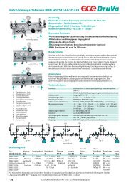
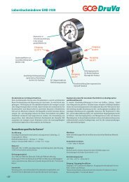
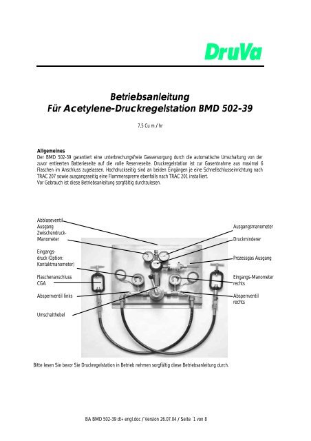
1 – TECHNISCHE DATENmaximaler Eingangsdruck: : 25 barmaximaler Ausgangsdruck : 1,5 barReservedruck: 3 barNenngasdurchfluss : 7.5 qm 3/hArbeitstemperatur: -20°C bis und 60° C2 – ARBEITEN VOR INBETRIEBNAHME• Jede Station ist einzeln verpackt. Nach Öffnen der Verpackung sicherstellen, dass die Station keine Beschädigungaufweist.• Diese Anlage ist gereinigt und öl- und fettfrei. Achten Sie bitte während der Montage darauf, dass kein Öl und Fettan diese Anlage gelangt.• Druckgasflaschen müssen in einem gut belüfteten Raum und frei von Wärmequellen aufgestellt werden.• Flaschen müssen gegen Umfallen gesichert werden.3 – MONTAGE DER DRUCKREGELSTATIONFür diese Arbeiten sehen Sie bitte auch auf die erste Seite der Kurzbeschreibung.• Befestigen Sie die Montagewinkel sicher an der Wand.• Entfernen Sie die Schutzkappen von den Eingangsstutzen.• Montieren Sie die zwei Montagewinkel zusammen mit den zugehörigen Bolzen.• Stellen Sie sicher, dass die erforderlichen Sicherheitseinrichtungen ein- und ausgangsseitig derDruckregelstation entsprechend TRAC206 bzw. PREN (W100121162) installiert sind.• Überprüfen Sie die Hochdruckschläuche auf Sauberkeit.• Überprüfen Sie die O-Ringe sowie Dichtringe auf Beschädigung, bevor Sie die Schläuche an die Druckregelstationanschliessen.• Verbinden Sie die vorhandenen Rohrleitungen an die Druckregelstation.FÜHREN SIE FOLGENDE SCHRITTE NIEMALS DURCH, OHNE DIE DRUCKREGELSTATIONORDNUNGSGEMÄSS EINGANGSSEITIG SOWIE AUSGANGSSEITIG ANGESCHLOSSEN ZU HABEN:• Öffnen Sie langsam die Flaschenventile.• Überprüfen Sie die Schlauchverbindungen auf evtl. Leckagen unter Zuhilfenahme von Lecksuchsprays oder einfacherSeifenlösung.• Öffnen Sie langsam das linke Absperrventil der Druckregelstation.• Überprüfen Sie wiederum die Verbindungen zur Druckregelstation auf evtl. Undichtigkeiten.• Liegen keine Undichtigkeiten vor, schließen Sie wieder das Absperrventil und stellen Sie die Gaszufuhr an denFlaschen ab.4 – BETRIEB UND ARBEITSWEISE VOM <strong>BMD</strong> <strong>502</strong>-<strong>39</strong>Diese Druckregelstation garantiert eine unterbrechungsfreie Gasversorgung. Somit werden die Anforderungen an hoheVersorgungswirtschaftlichkeit in vielen speziellen Prozessen realisiert. Der <strong>BMD</strong> <strong>502</strong>-<strong>39</strong> sichert eine kontinuierlicheGasversorgung bei automatischer Umschaltung von der entleerten Flaschenseite zur Reservenflaschenseite.BA <strong>BMD</strong> <strong>502</strong>-<strong>39</strong> <strong>dt+</strong> <strong>engl</strong>.doc / Version 26.07.04 / Seite 2 von 8
Die Funktion und Umschaltung vom <strong>BMD</strong> <strong>502</strong>-<strong>39</strong> erfolgt in 4 Schritten:1. Schritt:Beide Batteriehälften sind gefüllt und beide Absperrventile geöffnet.Der Umschalthebel zeigt auf die linke Seite. Dies istdie Seite, aus der das Acetylen entnommen wird und die rechteSeite ist die Reserveseite. Links = Arbeitsseite.2. Schritt:Die Arbeitsseite ist nun nahezu entleert.Der <strong>BMD</strong> <strong>502</strong>-<strong>39</strong> schaltet nun auf die Reserveseiteautomatisch um, wobei der Arbeitsdruck um 3 bar abfällt.Der Umschalthebel zeigt immer noch auf die linke Seite.LINKS = LeerRECHTS = Reserveseite und jetzt auch Arbeitsseite.3. Schritt:Schließen Sie das linke Absperrventil und tauschen Sie die entleertenFlaschen durch gefüllte Acetylenflaschen aus.Um wieder einen Arbeitsdruck von 5 bar zu erzielen, schalten Sie den Hebelbitte auf die rechte Seite. Nun ist die rechte Seite die Arbeitsseite.Die linke Seite = Reserveseiterechte = Arbeitsseite4. Schritt:Beide Batteriehälften besitzen nun vollen Flascheninhalt und beideAbsperrventile an der Druckregelstation sind geöffnet. DerUmschalthebel zeigt auf die rechte Batteriehälfte.LINKE = ReserveseiteRECHTS = ArbeitsseiteAchtung: Die Stellung des Umschalthebels zeigt immer diejeweilige Arbeitsseite an.5 – WARTUNGDer <strong>BMD</strong> <strong>502</strong>-<strong>39</strong> benötigt keine spezielle Wartung. Wie immer stellen Sie jedoch sicher, dass alle Anschlüsse und dieDichtflächen sich in einem einwandfreien Zustand befinden und untersuchen Sie die Station regelmäßig auf evtl. Leckagen.BA <strong>BMD</strong> <strong>502</strong>-<strong>39</strong> <strong>dt+</strong> <strong>engl</strong>.doc / Version 26.07.04 / Seite 3 von 8
6 – BEDIENPERSONAL• Das mit dem Betrieb dieser Druckregelstation beauftragte Bedienpersonal sollte Erfahrungen im Umgang mitDruckgasflaschen und Brenngasen besitzen.• Das Bedienpersonal muss mit den Gefahren vertraut und in der Lage sein, den Füllzustand für Acetylenflaschen zubeurteilen.• Das Bedienpersonal muss mit erforderlichen Sicherheits- und Notfalleinrichtungen vertraut sein, z.B. Feuerlöscher,Atemschutzgeräte etc.WARNUNGDie Ventile müssen langsam geöffnet werden, damit Schaden an der Druckregelanlage vermieden wird!8- Dieses DokumentTechnische Änderungen vorbehalten. Printed in Germany.Version 01-0704 BA_<strong>BMD</strong> <strong>502</strong>-<strong>39</strong>.doc Manufacturer 2004.<strong>GCE</strong> DruVa GmbH & Co. KGWerner-von-Braun-Str.5-769214 EppelheimDeutschlandTel.: + 49 6221 7921-0Fax + 49 6221 7921-32BA <strong>BMD</strong> <strong>502</strong>-<strong>39</strong> <strong>dt+</strong> <strong>engl</strong>.doc / Version 26.07.04 / Seite 4 von 8
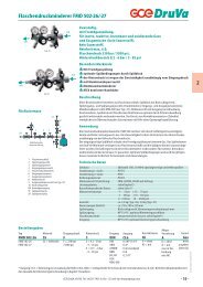
Instructions manualAcetylene panel <strong>BMD</strong> <strong>502</strong>-<strong>39</strong>7,5 Cu m / hrThe <strong>BMD</strong> <strong>502</strong>-<strong>39</strong> provides an uniterrupted supply of gas, the requirement may be due to the critical processes or tosave downtime due to production hold-ups. Whatever the reason an <strong>BMD</strong> <strong>502</strong>-<strong>39</strong> will ensure continuity of gas flow byautomatically changing from an empty bank to the full one.The unit is specially designed for use with industrial gas ACETYLENE and for connecting at maximum 6 cylinders.Relief valueOutletIntermediateGauge lowPressureInlet pressure LHBank (option:Contact alarmGauge)InletconnectionCGASwitch over LeverLow pressureRegulatorProcess gasOutletInlet pressureRH bankShut-off valveRH bankShut-off valve LHBefore using this appliance, we recommend that you read very carefully all information contained in this document.BA <strong>BMD</strong> <strong>502</strong>-<strong>39</strong> <strong>dt+</strong> <strong>engl</strong>.doc / Version 26.07.04 / Seite 5 von 8
1 - SPECIFICATIONSMaximum inlet pressure : 25 bar / 363 psiMaximum outlet pressure : 1.5 bar / 22 psiWorking pressure : 5 bar / 73 psiReserve pressure : 3 bar / 44 psiNominal Flow: 7.5 Cu m/h (Media Air)Working temperature : -20 C Q +60 C / -4 to 140° F2 – PRECAUTIONARY MEASURES BEFORE MOUNTING• Each manifold is packaged in a single pacel. After opening, ensure that the manifold does not show damage.• This appliance is completely cleaned and free from oil and gase. Do not pollute it during mounting.• Cylinders have to be placed in a ventiated room, away from sudden temperature changes.• Cylinders have to be fixed on the wall securely.3 – ASSEMBLY OF <strong>BMD</strong> <strong>502</strong>-<strong>39</strong>For this section please refer to the diagram on the front page of book et.• Fix wall mounting bracket securely to wall.• Remove protective caps from inlet stems.• Assembly the two mounting brackets together using bolts provided.• Insure suitable Safety devices are fitted up stream and down stream of the <strong>BMD</strong> <strong>502</strong>-<strong>39</strong> inaccordance with, Draft prEN (WI00121162)• Check cleanness of high-pressure hoses. (Or pigtail depending on application).• Check ‘O’ ring / PTFE seals on the hoses for damage before attaching to autochange (if applicable).• Connect existing pipe work to outlet connection (G 3/8 LH male cone recess).THE FOLLOWING STEPS SHOULD NOT BE CARRIED OUT UNLESS THE INLETAND OUTLETCONNECTIONS ARE PROPERLY CONNECTED• Slowly open gas supply to <strong>BMD</strong> <strong>502</strong>-<strong>39</strong>.• Check hose connection for leaks using a suitable leak detection solution.• Open autochange left hand shut off valve slowly.• Check autochange outlet connection for leaks.• Once satisfied no leaks are present, colse shut off valve and turn off gas supply ready for use.4 – OPERATION OF <strong>BMD</strong> <strong>502</strong>-<strong>39</strong>The <strong>BMD</strong> <strong>502</strong>-<strong>39</strong> provides an uniterrupted supply of gas; the requirement may be due to the critical process or to savedowntime due to production hold-ups. Whatever the reason an autochange unit will ensure continuity of gas low byautomatically changing from an empty bank of cylinders to a full one.BA <strong>BMD</strong> <strong>502</strong>-<strong>39</strong> <strong>dt+</strong> <strong>engl</strong>.doc / Version 26.07.04 / Seite 6 von 8
Operation of the <strong>BMD</strong> <strong>502</strong>-<strong>39</strong> can be described in 4 stages:First stage:Both suppies are full, and both shut-off valves are opened.The switch lever is on the LEFT. This is the working side.LEFT = Working sideRIGHT = ReserveSecond stage:Working supply is empty.The manifold switches onto reserve supply, working pressuredrops to 3 bar / 44 psiThe switch lever is still on LEFTLEFT = EmptyRIGHT = Reserve (Working side)Third stage:Closing the left shut-off valve, the left supply must be changed to a full one.To rise pressure up to 5 bar / 73 psi, turn the switch lever on the RIGHT.Then, the right side becomes working sideSwitch lever is on the RIGHTLEFT = ReserveRIGHT = Working sideFourth stage:Both sides are full and the two shut-off valves are opened.The switch is on the RIGHT. This is the working side.LEFT = ReserveRIGHT = WorkingNote: Position of the switch lever indicates operating side5 – MAINTAINCEThe <strong>BMD</strong> <strong>502</strong>-<strong>39</strong> will not need special maintaince. However make sue all seating surfaces, hard seat or soft seat arekept in good working condition and regularly checked for possible leakage.6 – PERSONNEL (Who enter the storage ara) should be,Responsible and competent to maintain the gas store and its contents.Familiar with and able to identify the contents of the gas containers and they’re potential hazards.BA <strong>BMD</strong> <strong>502</strong>-<strong>39</strong> <strong>dt+</strong> <strong>engl</strong>.doc / Version 26.07.04 / Seite 7 von 8
Familiar with the operation and use of the safety and emergency equipment provided (e.g. Fire extinguishers, breatingapparatus etc.)WARNINGALL VAVES MUST BE OPEN SLOWLY,THIS WILL PREVENT DAMAGE TOTHE <strong>BMD</strong> <strong>502</strong>-<strong>39</strong>7- This documentWe reserve the right to make technical alterations which improve the product. Pinted in Germany.Version 01-0704 BA_<strong>BMD</strong> <strong>502</strong>-<strong>39</strong>.doc Manufacturer 2004.<strong>GCE</strong> DruVa GmbH & Co. KGWerner-von-Braun-Str.5-769214 EppelheimGermanyPhone + 49 6221 7921-0Fax + 49 6221 7921-32BA <strong>BMD</strong> <strong>502</strong>-<strong>39</strong> <strong>dt+</strong> <strong>engl</strong>.doc / Version 26.07.04 / Seite 8 von 8