Upper Cutoff Frequency of a Common-Emitter Amplifier
Upper Cutoff Frequency of a Common-Emitter Amplifier
Upper Cutoff Frequency of a Common-Emitter Amplifier
- No tags were found...

Create successful ePaper yourself
Turn your PDF publications into a flip-book with our unique Google optimized e-Paper software.
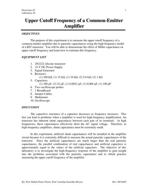
Electronics IILaboratory #11<strong>Upper</strong> <strong>Cut<strong>of</strong>f</strong> <strong>Frequency</strong> <strong>of</strong> a <strong>Common</strong>-<strong>Emitter</strong><strong>Amplifier</strong>OBJECTIVESThe purpose <strong>of</strong> this experiment is to measure the upper cut<strong>of</strong>f frequency <strong>of</strong> acommon-emitter amplifier due to parasitic capacitances using the high-frequency model<strong>of</strong> a BJT transistor. You will be able to demonstrate the effect <strong>of</strong> Miller capacitance onupper cut<strong>of</strong>f frequency and learn how to estimate this frequency.EQUIPMENT LIST1. 2N2222 silicone transistor2. 15-V DC Power Supply3. Signal Generator4. Resistors:(1) 100 kΩ, (1) 15 kΩ, (1) 10 kΩ, (2) 5.6 kΩ, (2) 1 kΩ5. Capacitors:(1) 100 µF, (2) 22 µF, (1) 0.0022 µF, (1) 0.068 µF, (1) 100 pF6. Two oscilloscope probes7. 1 Breadboard8. Jumper Cables9. Multimeter10. OscilloscopeDISCUSSIONThe capacitive reactance <strong>of</strong> a capacitor decreases as frequency increases. Thisfact can lead to problems when a amplifier is used for high-frequency amplification. Antransistor has inherent shunt capacitances between each pair <strong>of</strong> its terminals. At highfrequencies, these capacitances effectively short the AC signal voltage. Therefore, inhigh-frequency amplifiers, shunt capacitance must be extremely small.In this experiment, artificial shunt capacitances will be installed in the amplifiercircuit because it is extremely difficult to measure the actual parasitic capacitances <strong>of</strong> thetransistor. Since the artificial capacitances are much larger than the real parasiticcapacitances, the parallel combination <strong>of</strong> real capacitances and artificial capacitors isapproximately equal to the values <strong>of</strong> the artificial capacitors. The objective <strong>of</strong> thislaboratory is to investigate the high-frequency response <strong>of</strong> the amplifier to gain insightinto the problems associated with the parasitic capacitance and to obtain practicemeasuring the upper cut<strong>of</strong>f frequency <strong>of</strong> the amplifier.By: Pr<strong>of</strong>. Rubén Flores Flores, Pr<strong>of</strong>. Caroline González Rivera Rev: 09/16/05
Electronics IILaboratory #12RsVsRB Rpi CA CB RL'The upper cut<strong>of</strong>f frequency is where the voltage gain <strong>of</strong> the amplifier drop –3 dBor 0.707 time the midband voltage gain value For the equivalent circuit <strong>of</strong> a commonemmiteramplifier in Figure 1, the upper cut<strong>of</strong>f frequency due to input shunt capacitanceC A can be calculated using the following equations:ICQCARrπ's= CV=IBEfTc= R⎛= β⎜⎝ RCQBB( C+ CA// RCBRE'LSβ; V) =T// rVB− 0.7+ R ⋅( β + 1)( 1−A )= RCMR's2π⋅ Rπ;1B; A// R⋅CLVMA= R= 26mV@300⎞⎟;⎠B1// R2KVccR2=R + R1'L− β ⋅ R=rThe equation for calculating Miller capacitance is only valid for the invertingamplifier. Since the non-inverting amplifier is not affected by Miller capacitance, it is<strong>of</strong>ten used in very high-frequency amplification. It is important to notice that A M doesnot take into account the voltage divider between the internal signal-source resistance andthe input resistance <strong>of</strong> the amplifier. Therefore, the value <strong>of</strong> A M is not equal to theoverall gain (A S ) from source-to-load, V L /V S .The upper cut<strong>of</strong>f frequency due to output shunt impedance C B can be calculatedusing the following equation:oπ2By: Pr<strong>of</strong>. Rubén Flores Flores, Pr<strong>of</strong>. Caroline González Rivera Rev: 09/16/05
Electronics IILaboratory #13fCc( CB) =2 π'⋅ RLB= CCE+ C1CB⋅CBAM⋅A−1Provided that f c (C A ) and f c (C B ) are not close in value, the actual upper cut<strong>of</strong>ffrequency <strong>of</strong> the amplifier is approximately to the smaller <strong>of</strong> the two frequencies.PROCEDURE1) Using the digital multimeter, measure the β <strong>of</strong> the BJT transistor and theresistors values <strong>of</strong> the circuit resistors. Complete table 1.2) To measure the bias current (I cq ) <strong>of</strong> the amplifier, connect the followingcircuit. Remember this current is DC. Determine the value <strong>of</strong> the dynamicresistance <strong>of</strong> the transistor (r π ). Complete table 1.VCC15VM100kohmR15.6kohmRc22uFC2R65.6kohm50mV35.36mV_rms400Hz0DegVs+Vin-22uFC115kohmR21kohmRe100uFCe+VL-10kohmRLBy: Pr<strong>of</strong>. Rubén Flores Flores, Pr<strong>of</strong>. Caroline González Rivera Rev: 09/16/05
Electronics IILaboratory #143) Set the signal generator voltage and frequency to 50 mV peak and 400 Hzrespectively. Make sure that the signal generator termination is 50 Ω.4) To verify that the amplifier is working, measure with the oscilloscope thepeak-to-peak voltages <strong>of</strong> V in , V L and V s . These values can be used todetermine the midband voltage gainfrom load-to-sourceA M = VLVinand the voltage gainA = V V . Complete table 2.SLS5) To measure the high-frequency response <strong>of</strong> the common-emitter amplifier,connect the parasitic capacitors (C CB ,C BE ,C CE ) as illustrated in the figure.These capacitors are intentionally made much larger than the normal devicecapacitances for reasons outlined in the discussion section.VCC15V100kohmR15.6kohmRc22uFC2100pFCcb5.6kohmRs+22uFC10.0022uFCce+50mV35.36mV_rms400Hz0DegVsVin-15kohmR20.068uFCbe1kohmRe100uFCeVL-10kohmRL6) Now increase the frequency <strong>of</strong> the signal generator until the peak-to-peakvoltage <strong>of</strong> the load decreases to 0.707 times the value at 400 Hz. This is theoverall upper cut<strong>of</strong>f frequency <strong>of</strong> the amplifier. (Table 4).7) Return the signal generator frequency back to 400 Hz and start. Increase thefrequency <strong>of</strong> the generator to each frequency in Table 3 measuring values <strong>of</strong>By: Pr<strong>of</strong>. Rubén Flores Flores, Pr<strong>of</strong>. Caroline González Rivera Rev: 09/16/05
Electronics IILaboratory #15V L at each frequency. These voltage values will be used to plot the highfrequencyresponse <strong>of</strong> the amplifier.8) To determine the upper cut<strong>of</strong>f frequency due to the input capacitance C Aremove the output capacitance C CE . Return the signal generator frequencyback to 400 Hz and again start increasing the frequency until the peak-to-peakvoltage <strong>of</strong> the load decreases to 0.707 times the value at 400 Hz. Thisfrequency is f c (C A ). (Table 4).9) To determine the upper cut<strong>of</strong>f frequency due to the output capacitance C Bremove the input capacitances C BE and reconnect C CE capacitor. Return thesignal generator frequency back to 400 Hz and again start increasing thefrequency until the peak-to-peak voltage <strong>of</strong> the load decreases to 0.707 timesthe value at 400 Hz. This frequency is f c (C B ). (Table 4).10) Which <strong>of</strong> the two cut<strong>of</strong>f frequencies from steps 8 and 9 determine the overallcut<strong>of</strong>f frequency <strong>of</strong> the amplifier (step 6)?11) Using table 2, plot the amplifier frequency response (A V (dB) vs. freq.). The⎛ VdB)= 20 ⋅ log⎜⎝Vvoltage gain in decibels is equal to Av(L. From theingraph identify the overall cut<strong>of</strong>f frequency. Remember this happen when thegain drops 3 dB from the midband voltage gain in decibels.⎟ ⎞⎠By: Pr<strong>of</strong>. Rubén Flores Flores, Pr<strong>of</strong>. Caroline González Rivera Rev: 09/16/05
Electronics IILaboratory #16DATATable 1: Steps 1 and 2<strong>Amplifier</strong>’s MeasuredParameters ValuesR 1R 2R SR CR ER LβI CQTable 2: Midband Voltage Gain (f = 400 Hz). Step 4V L (peak-to-peak) A V = VLVinA s = VLVSTable 3: <strong>Frequency</strong> Response (Step 6)<strong>Frequency</strong> (Hz) V L (peak-to-peak) s L S4006008001k1.2k1.4k1.6k1.8k2k3k4k5k10k16k20kTable 4: <strong>Amplifier</strong>’s <strong>Cut<strong>of</strong>f</strong> Frequencies<strong>Upper</strong> cut<strong>of</strong>fStep Numberfrequency689A = V V A V = VLVinBy: Pr<strong>of</strong>. Rubén Flores Flores, Pr<strong>of</strong>. Caroline González Rivera Rev: 09/16/05