Equipment/ functions - Process Valve Solutions
Equipment/ functions - Process Valve Solutions
Equipment/ functions - Process Valve Solutions

You also want an ePaper? Increase the reach of your titles
YUMPU automatically turns print PDFs into web optimized ePapers that Google loves.
ISO 9001<br />
ISO 14001<br />
Certificate Registration No.<br />
12 100 4269<br />
12 104 4269<br />
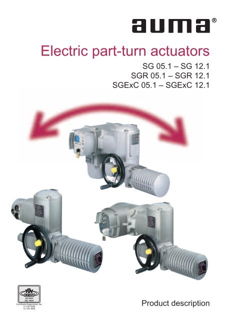
Electric part-turn actuators<br />
SG 05.1 – SG 12.1<br />
SGR 05.1 – SGR 12.1<br />
SGExC 05.1 – SGExC 12.1<br />
Product description
2<br />
Part/turn valves find applications in<br />
many industries as shut-off devices<br />
and increasingly to control the flow.<br />
Without automation the smooth function<br />
of industrial processes would be<br />
impossible. AUMA’s electric<br />
part-turn actuators play an important<br />
role in this case. For part-turn valves<br />
with a nominal diameter of approx.<br />
DN 40 and above, AUMA part-turn<br />
actuators from the SG 05.1 –<br />
SG 12.1 range are the best automation<br />
solution.<br />
AUMA is a leading manufacturer of<br />
electric actuators. More than 40<br />
years’ experience in conjunction with<br />
the innovative spirit of our engineers<br />
are the sound basis for constant<br />
improvement and further developments.<br />
AUMA offer a wide range of actuators<br />
which fulfils all the usual requirements<br />
of valve automation.<br />
Multi-turn actuators from 10 to<br />
32,000 Nm, part-turn actuators from<br />
25 to 360,000 Nm or linear thrust<br />
units from 4 to 217 kN. All kinds of<br />
valves can be automated and operated<br />
by rotary and linear movement.<br />
Sales support and after sales service<br />
are provided worldwide by regional<br />
offices, service centres, AUMA subsidiaries<br />
and representatives. This<br />
ensures that experienced sales<br />
engineers and qualified service technicians<br />
are close to the customer.<br />
They are prepared for responding to<br />
enquiries, executing orders or furnishing<br />
after-sales service.<br />
Table of contents<br />
Applications 3<br />
<strong>Equipment</strong>/ Summary of <strong>functions</strong> 5<br />
<strong>Equipment</strong>/ <strong>functions</strong> 6<br />
Type designation 6<br />
Open-close duty 6<br />
Modulating duty 7<br />
Comparison short-time and intermittent duty 7<br />
Adjustable swing angle 8<br />
Seating 8<br />
Adjustable torques 9<br />
Overload protection against torque peaks 9<br />
DUO limit switching/ intermediate position switches (option) 10<br />
Limit and torque switches 10<br />
Magnetic limit and torque transmitter (MWG) (option) 11<br />
Non-intrusive setting (option) 12<br />
Position/ torque feedback signal (option) 12<br />
Running indication (option) 13<br />
Heater 13<br />
Design principle 14<br />
<strong>Equipment</strong>/ <strong>functions</strong> 16<br />
Motors 16<br />
Operating times 16<br />
Motor protection 17<br />
Interfaces 18<br />
Electrical connection 18<br />
Wiring diagrams 20<br />
<strong>Valve</strong> attachment 20<br />
Coupling 20<br />
Integral controls 21<br />
Integral controls (option) 21<br />
Which type of controls? 22<br />
Advantages of integral controls (option) 23<br />
Ambient conditions 24<br />
Enclosure protection 24<br />
Corrosion protection/ Colour 24<br />
Ambient temperatures 24<br />
Explosion protection 25<br />
Lifetime 25<br />
Mounting positions 25<br />
Other information 26<br />
EU-Directives 26<br />
Functional tests 26<br />
Further literature 26<br />
Index 27<br />
We reserve the right to alter data according to improvements made.<br />
Figures and diagrams are not binding.
AUMA part-turn actuators are<br />
employed wherever an automated<br />
rotatry movement of 360° or less<br />
driven by an electric motor is<br />
required. Examples are valves such<br />
as butterfly valves and ball valves.<br />
Chemical<br />
industry<br />
■ Chemical industry<br />
■ Petrochemical industry<br />
■ Pharmaceutical industry<br />
Food industry ■ Breweries<br />
■ Dairies<br />
■ Sugar industry<br />
Energy ■ Power plants<br />
■ Air pollution control<br />
■ District heating<br />
Water/ Wastewater<br />
Applications<br />
■ Water works<br />
■ Sewage treatment<br />
■ Pump stations<br />
Others ■ Air conditioning and ventilation<br />
■ Ship building industry<br />
■ Steel mills<br />
■ Cement plants<br />
3
4<br />
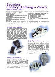
Versions<br />
Part-turn actuator with<br />
AUMA MATIC integral<br />
controls<br />
Part-turn actuator with<br />
AUMATIC controls on<br />
wall bracket<br />
Definition of part-turn<br />
actuators according to<br />
ISO 5211<br />
A part-turn actuator is an actuator<br />
(actor), which transmits a torque to<br />
the valve for less than one full revolution.<br />
It need not be capable of withstanding<br />
thrust.
●Standard<br />
■Option<br />
<strong>Equipment</strong> / <strong>functions</strong><br />
Interfaces<br />
Service conditions<br />
<strong>Equipment</strong>/ Summary of <strong>functions</strong><br />
SG<br />
05.1 – 12.1<br />
SGR<br />
05.1 – 12.1<br />
SGExC<br />
05.1 – 12.1<br />
Description<br />
on page<br />
Open-close duty<br />
Modulating duty<br />
Swing angle adjustable<br />
Mechanical end stops<br />
Seating<br />
– Limit seating<br />
– Torque seating<br />
Overload protection<br />
DUO (Four train gear) limit switching<br />
Limit and torque switches<br />
– Tandem switch<br />
– Triple switch<br />
– Switches with gold plated contacts<br />
Magnetic limit and torque transmitter (MWG)<br />
Non-intrusive setting<br />
Position feedback/ torque feedback signal<br />
Mechanical position indicator<br />
Blinker transmitter for running indication<br />
Operating time adjustable<br />
Manual operation<br />
●<br />
●<br />
●<br />
●<br />
●<br />
●<br />
●<br />
■<br />
●<br />
■<br />
■<br />
■<br />
■<br />
■<br />
■<br />
●<br />
■<br />
■<br />
●<br />
●<br />
●<br />
●<br />
●<br />
●<br />
●<br />
●<br />
■<br />
●<br />
■<br />
■<br />
■<br />
■<br />
■<br />
■<br />
●<br />
■<br />
●<br />
●<br />
●<br />
●<br />
●<br />
●<br />
●<br />
●<br />
■<br />
●<br />
■<br />
■<br />
■<br />
■<br />
■<br />
■<br />
●<br />
■<br />
■<br />
●<br />
6<br />
7<br />
8,14<br />
14<br />
8<br />
8<br />
8<br />
9<br />
10<br />
10<br />
10<br />
10<br />
10<br />
11<br />
12<br />
12<br />
14<br />
13<br />
16<br />
15<br />
Heater<br />
– in switch compartment<br />
– Motor heater<br />
●<br />
■<br />
●<br />
■<br />
●<br />
■<br />
13<br />
13<br />
Motors<br />
– 3-phase AC motors<br />
– 1-phase AC motors<br />
– DC motors<br />
●<br />
■<br />
■<br />
● ●<br />
■<br />
■<br />
15, 16<br />
15, 16<br />
15, 16<br />
15, 16<br />
Motor protection<br />
– Thermoswitches<br />
– PTC thermistor<br />
Integral controls<br />
●<br />
■<br />
■<br />
●<br />
■<br />
■<br />
■<br />
●<br />
■<br />
17<br />
17<br />
17<br />
21 - 23<br />
Electrical connections<br />
– AUMA plug/ socket connector<br />
– Double sealed<br />
– Plug/ socket connector for explosion-proof actuators<br />
– Plug-in terminal connection<br />
– Plug cover in special versions<br />
<strong>Valve</strong> attachment according to ISO 5211<br />
– Coupling<br />
– Coupling with bore<br />
●<br />
■<br />
■<br />
■<br />
●<br />
●<br />
■<br />
●<br />
■<br />
■<br />
■<br />
●<br />
●<br />
■<br />
●<br />
●<br />
■<br />
■<br />
●<br />
●<br />
■<br />
14, 18, 19<br />
18, 19<br />
18<br />
18, 19<br />
18, 19<br />
19<br />
15, 20<br />
15, 20<br />
20<br />
Ambient conditions<br />
– Enclosure protection IP67<br />
– Enclosure protection IP68<br />
– High temperature version<br />
– Low temperature version<br />
– Corrosion protection KN<br />
– Corrosion protection KS, KX<br />
– Version with cast iron housing<br />
Explosion protection<br />
EU Directives<br />
Functional tests<br />
●<br />
■<br />
■<br />
■<br />
●<br />
■<br />
■<br />
●<br />
●<br />
●<br />
■<br />
■<br />
●<br />
■<br />
■<br />
●<br />
●<br />
●<br />
■<br />
■<br />
●<br />
■<br />
■<br />
●<br />
●<br />
●<br />
24<br />
24<br />
24<br />
24<br />
24<br />
24<br />
24<br />
24<br />
24, 25<br />
26<br />
26<br />
5
6<br />
<strong>Equipment</strong>/ <strong>functions</strong><br />
Type designation<br />
Version for modulating duty<br />
Explosion-proof part-turn actuator acc. to ATEX Directive 94/9/ EC<br />
Size (standard flange size according to EN ISO 5211)<br />
Device generation (SG x.2 for ship building, SG x.3 for lower torques)<br />
Open-close duty<br />
Input<br />
<strong>Valve</strong><br />
Actuator<br />
for open-close duty<br />
The usual valve positions in<br />
open-close duty are the end positions<br />
OPEN and CLOSED. Upon<br />
receiving an appropriate command<br />
the actuator moves the valve to one<br />
of the two end positions or, if necessary,<br />
to a pre-defined intermediate<br />
position.<br />
The valves are operated relatively<br />
seldom, the time intervals can span<br />
between a few minutes up to several<br />
months.<br />
<strong>Valve</strong> position<br />
trun<br />
t run max =15min(30min)<br />
Typical operation process in OPEN-CLOSE duty<br />
SGRExC 05.1<br />
Type of duty for part-turn<br />
actuators for open-close duty<br />
(SG, SGExC)<br />
AUMA part-turn actuators SG for<br />
open-close service are rated for<br />
short-time duty S2 - 15 min. The<br />
explosion-proof version SGExC are<br />
rated for S2 - 10 min. Description of<br />
the types of duty on page 7.<br />
t
Modulating duty<br />
Input signal from<br />
process controller<br />
Feedback signal<br />
to process controller<br />
<strong>Valve</strong> position<br />
Transmitter<br />
(Sensor)<br />
Positioner<br />
<strong>Valve</strong> position feedback<br />
Controlled variable<br />
Typical operation process in modulating duty<br />
Comparison short-time and intermittent duty<br />
<strong>Valve</strong><br />
Actuator<br />
for<br />
modulating<br />
duty<br />
Type of duty according to VDE 0530 / IEC 34-1<br />
Short-time duty S2<br />
The operation time at a constant load is short, so that<br />
thermal equilibrium is not reached. The pause is long<br />
enough for the machine to cool down to ambient temperature.<br />
The duration of the short-time operation is limited<br />
to 15 min (10 min, 30 min).<br />
<strong>Equipment</strong>/ <strong>functions</strong><br />
t<br />
The controlled variable in a modulating<br />
application is affected by many<br />
influences. A change of the reference<br />
input signal, pressure fluctuation<br />
in the pipeline and temperature<br />
variations influence the process in<br />
such a way that a frequent adjustment<br />
of the MOV is required. For<br />
sensitive modulating applications<br />
the starts may be in intervals of a few<br />
seconds.<br />
Therefore high demands are placed<br />
on actuators for this duty. Mechanical<br />
components and the motor must<br />
be designed appropriately to withstand<br />
a large number of operations<br />
with no decline in the required modulating<br />
accuracy.<br />
Type of duty for part-turn actuators<br />
for modulating duty (SGR)<br />
AUMA part-turn actuators SGR for<br />
modulating service are rated for<br />
intermittent duty S4 - 25 %.<br />
Intermittent duty S4<br />
The duty is a sequence of identical cycles which consist<br />
of starting time, operation time with constant load and<br />
rest period. The rest period allows the machine to cool<br />
down so that thermal equilibrium is not reached. The relative<br />
on- time at S4 - 25 % or S4 - 50 % is limited to 25 %<br />
and 50 % respectively.<br />
Permissible number of starts<br />
The max. permissible number of starts for all part-turn<br />
actuator sizes for modulating duty SGR 05.1 – SGR 12.1<br />
are 600 starts per hour [c/h].<br />
7
8<br />
<strong>Equipment</strong>/ <strong>functions</strong><br />
Adjustable swing angle<br />
During manual operation the swing<br />
angle is limited via the internal end<br />
stops. If the customer requirements<br />
have not been mentioned in the<br />
order, the actuator is supplied with a<br />
swing angle of 90° The swing angle<br />
may be subsequently adjusted<br />
within a range of 80° – 110°. The<br />
operating time is extended or<br />
reduced accordingly.<br />
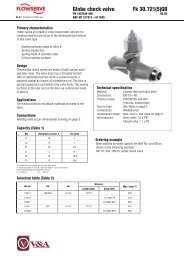
Seating<br />
Depending on the design of the valve<br />
to be operated, end position switching<br />
either limit seating, i.e. by measuring<br />
the valve travel completed, or<br />
torque seating, i.e. after reaching a<br />
defined torque. For this purpose, the<br />
Limit seating<br />
Speed<br />
Other swing angle ranges<br />
(option)<br />
On request the part-turn actuators<br />
may be supplied with different swing<br />
angle ranges.<br />
The following swing angle ranges<br />
are available:<br />
■ 30° – 40°<br />
■ 40° – 55°<br />
■ 55° – 80°<br />
■ 80° – 110° (standard)<br />
■ 110° – 160°<br />
■ 160° – 230°<br />
■ 230° – 320°<br />
The actuator runs at nominal output speed up to the set<br />
tripping point P. Due to the high reduction ratio and the<br />
consequently low output speeds (3.75 rpm at the shortest<br />
operating time 4 s for 90°) the overrun may be ignored.<br />
actuator is equipped with two independent<br />
measuring systems, i.e.<br />
limit switching and torque switching.<br />
The type of seating has to be taken in<br />
P<br />
Torque seating<br />
Set tripping torque<br />
Travel<br />
Travel<br />
OPEN CLOSED OPEN<br />
CLOSED<br />
Torque<br />
account both when setting the actuator<br />
and in the actuator control. However,<br />
the processing of signals for<br />
the two types of seating differs.<br />
After starting from the end position OPEN, the actuator<br />
runs in direction CLOSE. In end position CLOSED the<br />
torque increases within the valve seat until the actuator is<br />
automatically switched off after reaching the set value.
Adjustable torques<br />
Minimum and maximum tripping torques for part-turn actuators for open-close duty<br />
<strong>Equipment</strong>/ <strong>functions</strong><br />
Size SG 05.1 SG 07.1 SG 10.1 SG 12.1<br />
min. [Nm] 100 120 250 500<br />
max. [Nm] 150 300 600 1 200<br />
Torques for part/turn actuators for modulating duty<br />
Size SGR 05.1 SGR 07.1 SGR 10.1 SGR 12.1<br />
min. tripping torque [Nm] 100 120 250 500<br />
max. tripping torque [Nm] 150 300 600 1 200<br />
Torque for modulating [Nm] 50 100 200 400<br />
Overload protection against torque peaks<br />
The torque switching, used for<br />
torque seating in the end position<br />
(see page 8), serves as overload<br />
protection for the entire travel, even<br />
in the case of limit seating.<br />
If excessive torque builds up at the<br />
obturator in an intermediate position,<br />
e.g. due to a trapped object, the<br />
torque switching trips after reaching<br />
the set tripping torque.<br />
After the controls have processed<br />
the torque switch signal accordingly,<br />
the motor will be switched off. As a<br />
result, valve and actuator are protected<br />
from damage.<br />
If the limit switch signals are processed<br />
accordingly in the controls,<br />
you can distinguish between a normal<br />
torque switch tripping at the end<br />
Torque<br />
OPEN<br />
Set tripping torque<br />
Travel<br />
positions and tripping in an intermediate<br />
position (fault) caused by<br />
over-torque.<br />
CLOSED<br />
9
10<br />
<strong>Equipment</strong>/ <strong>functions</strong><br />
DUO limit switching/ intermediate position switches (option)<br />
With DUO limit switching an additional<br />
switching point can be set for each<br />
direction of rotation (intermediate<br />
position switches). The switching can<br />
be set to any valve position between<br />
the end positions. The switch will<br />
remain operated from set tripping<br />
point to end position if not more than<br />
120 turns of the hollow output shaft<br />
are in between.<br />
Limit and torque switches<br />
Versions<br />
The switch signal can be used for<br />
any purpose, e.g. to:<br />
■ signal a certain valve position<br />
tripped<br />
not<br />
tripped<br />
OPEN<br />
direction<br />
With the help of the switches, the<br />
mechanically measured travel (i.e.<br />
number of turns) and torque are converted<br />
into usable signals for the<br />
actuator controls. The switches are<br />
integrated into the control unit which<br />
contains four switches in the basic<br />
version:<br />
■ one limit switch each for the end<br />
positions OPEN and CLOSED,<br />
■ one torque switch each for the directions<br />
OPEN and CLOSE.<br />
The limit switches are tripped when<br />
an end position is reached and the<br />
torque switches are tripped when the<br />
set tripping torque is exceeded.<br />
■ to start an additional actuator<br />
which is mounted on a bypass<br />
valve<br />
■ to start or switch off any unit, e.g. a<br />
pump<br />
Switching<br />
points<br />
<strong>Valve</strong> position<br />
CLOSE<br />
direction<br />
If the actuator is supplied with<br />
DUO limit switching two more limit<br />
switches for intermediate positions<br />
are available.<br />
To meet the high demands regarding<br />
reliability, AUMA uses specially<br />
developed high quality<br />
microswitches with a snap action<br />
mechanism.<br />
In the basic version the switch contacts<br />
are of silver. For voltages<br />
between 5 V and 50 V and low current,<br />
switches with gold-plated contacts<br />
are recommended.<br />
Application/ Description Type of contacts<br />
Single switch Standard (NC and NO contacts not galvanically isolated) 1 NC and 1 NO contact<br />
(1 NC and 1 NO)<br />
Tandem switches (option) For switching two different potentials. The switches have two compartments with<br />
galvanically isolated switches in a common sealed housing. The two switches are<br />
operated together; one switch is leading, which should be used for signalisation.<br />
Triple switches (option) For applications where three different potentials are to be switched. The switch<br />
consists of one single and one tandem switch.<br />
Switch rating<br />
Type of current Switch rating Imax<br />
30 V 125 V 250 V<br />
AC (ind. load) cos ϕ = 0.8 5 A 5 A 5 A<br />
DC (resistive load) 2 A 0.5 A 0.4 A<br />
with gold plated contacts<br />
(recommended for controls with low voltage)<br />
Voltage min. 5 V, max. 50 V<br />
Current min. 4 mA, max. 400 mA<br />
Technical data<br />
2 NC and 2 NO contacts<br />
(2 NC und 2 NO)<br />
3 NC and 3 NO contacts<br />
(3 NC and 3 NO)<br />
Enclosure protection IP 66<br />
Operation via lever<br />
Contact elements two snap action contacts<br />
Contact material Silver (standard)<br />
Gold (option)<br />
Mechanical lifetime min. 2 x 10 6 cycles
Magnetic limit and torque transmitter (MWG) (option)<br />
The magnetic limit and torque transmitter<br />
converts the mechanical values<br />
of limit and torque into continuous<br />
electronic signals.<br />
The simultaneous use of integral<br />
controls which evaluate the signals<br />
is a prerequisite for the use of the<br />
MWG. This variant does not require<br />
Absolute travel measurement –<br />
without battery<br />
The valve position is determined<br />
using a so called multi-turn-absolute<br />
encoder.<br />
Four shafts, each with a ratio of 8:1,<br />
are used to convert the travel into an<br />
electronic signal. Each valve position<br />
is assigned an unambiguous<br />
combination of the 4 shaft positions.<br />
Magnets and hall sensors register<br />
the shaft positions electronically.<br />
As soon as the power supply has<br />
been restored after a power failure,<br />
the current valve position is immediately<br />
available; a reference operation<br />
is not required. Position changes<br />
due to manual operation during<br />
power failure are registered by the<br />
MWG even without supply voltage. A<br />
battery is not required.<br />
Torque – continuously available<br />
The proven design of the sliding<br />
worm provides the mechanical principle<br />
of torque sensing. A torque at<br />
the output drive results in an axial<br />
movement of the sliding worm<br />
against the spring action. With a<br />
lever, the axial movement is transformed<br />
into a rotary movement. Hall<br />
sensors convert this movement into<br />
an electronic signal.<br />
any switches for limit positions or<br />
torque.<br />
Actuators with MWG have the following<br />
advantages.<br />
■ Non-intrusive setting is possible<br />
(see page 12)<br />
Torque signal<br />
to the controls<br />
Travel/ position signal<br />
to the controls<br />
<strong>Equipment</strong>/ <strong>functions</strong><br />
■ A torque signal is permanently<br />
available. It can be used for<br />
switching off at the set tripping<br />
torque. It can also be transmitted<br />
for external use, for example for<br />
torque monitoring at the valve.<br />
11
12<br />
<strong>Equipment</strong>/ <strong>functions</strong><br />
Non-intrusive setting (option)<br />
If the actuator is equipped with<br />
a magnetic limit and torque<br />
transmitter (see page 11) and<br />
AUMATIC integral controls (see<br />
page 22) the actuator can be set<br />
non-intrusively. This means that the<br />
parameters can be set without having<br />
to open the actuator. Thereby<br />
several advantages are achieved:<br />
Position/ torque feedback signal (option)<br />
If the actuator is equipped with an<br />
MWG and AUMATIC integral controls,<br />
the valve position and the<br />
torque available in the valve are can<br />
be used as output signals. Even if<br />
there is no MWG installed in the actuator,<br />
the position of the valve can be<br />
transmitted as a continuous signal<br />
for remote position indication.<br />
Technical data potentiometer<br />
■ No tools are required for setting.<br />
■ The actuator need not be opened<br />
again after the electrical connection<br />
is completed. The electronic<br />
and mechanical components in<br />
the housing are well protected<br />
from ingress of water and dust.<br />
Position feedback is provided as an<br />
analogue feedback signal by:<br />
■ Precision potentiometer<br />
■ Electronic position transmitter<br />
RWG.<br />
Precision potentiometer Precision potentiometer in<br />
tandem version<br />
Linearity ≤ 1 %<br />
Output 0.5 W<br />
Resistance (standard) 0.2 kΩ 0.2/0.2 kΩ<br />
Resistance (option) 0.1 kΩ, 0.5 kΩ, 1.0 kΩ,<br />
5.0 kΩ<br />
Technical data RWG<br />
Output signal<br />
- 2-wire system<br />
- 3- or 4-wire system<br />
4 – 20 mA<br />
0/4 − 20 mA<br />
Supply voltage 24 V DC ±15% smoothed<br />
Lifetime min. 5 x 10 6 operations<br />
0.5/0.5 kΩ, 1.0/1.0 kΩ,<br />
5.0/5.0 kΩ, 0.2/5.0 kΩ<br />
■ The actuator can be set in potentially<br />
explosive atmospheres,<br />
without affecting the explosion<br />
protection.<br />
Electronic position transmitter<br />
RWG<br />
The actual position value is transmitted<br />
by a potentiometer and transformed<br />
by electronics into a current<br />
signal. Zero and span of the feedback<br />
signal can be easily adjusted by<br />
trimmer potentiometers.<br />
Inverse operation of the RWG is possible.<br />
Signal<br />
in mA 20<br />
4<br />
0<br />
0<br />
60<br />
Travel in %<br />
100<br />
Power supply unit for without<br />
integral controls<br />
For the voltage supply of all position<br />
transmitters we recommend the<br />
AUMA power supply unit PS 01.<br />
However, this unit must not be used<br />
in potentially explosive atmospheres<br />
or for intrinsically safe electric<br />
circuits.
Running indication (option)<br />
As an option the actuators are available<br />
with a blinker switch installed<br />
which can be used for the running<br />
indication. The contacts are available<br />
at the electrical connection.<br />
Heater<br />
Rating<br />
Technical data for heater in switch compartment<br />
Heater for actuators<br />
without integral controls<br />
Type of current Switch rating Imax<br />
30 V 125 V 250 V<br />
AC 5 A 5 A 5 A<br />
DC 2 A 0.5 A 0.4 A<br />
Heater in switch compartment<br />
(standard)<br />
Condensation in the actuator is possible<br />
due to wide fluctuation of the<br />
ambient temperature. The heater<br />
integrated in the control unit prevents<br />
this in general.<br />
The heater is rated for continuous<br />
duty. Therefore it should always be<br />
energized, but at the very least when<br />
the actuator is not operating.<br />
Heater for actuators with<br />
integral controls<br />
Heating element self-regulating PTC element Resistance type heater<br />
Voltage ranges 110 V – 250 V DC/AC<br />
24 V – 48 V DC/AC<br />
380 V – 400 V AC<br />
Output 5 W – 20 W 5 W<br />
24 V DC/AC<br />
(internal supply)<br />
<strong>Equipment</strong>/ <strong>functions</strong><br />
Motor heater<br />
(option)<br />
For operation in extremely low temperatures<br />
AUMA strongly recommends<br />
the use of a motor heater.<br />
This applies to actuators in extreme<br />
low temperature version from<br />
– 50 °C. The heater prevents actuator<br />
starting problems caused by<br />
extremely cold temperatures.<br />
13
14<br />
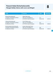
Design principle<br />
Control unit<br />
2 Depending on the type of valve the actuator<br />
must be switched-off in the end position by<br />
limit or torque switches.<br />
For this purpose two independent measuring systems<br />
(limit switches and torque switches) are provided<br />
within the control unit. They measure the travel<br />
or the torque required at the output drive, respectively.<br />
The switches signalize to the actuator controls that<br />
the set tripping points have been reached, which<br />
then switch off the motor.<br />
The control unit may optionally be equipped with a<br />
magnetic limit and torque transmitter. The transmitter<br />
converts the mechanical parameters limit and<br />
torque into continuous electronic signals. In combination<br />
with the integral controls AUMATIC tripping<br />
points and tripping torques can be set non-intrusively,<br />
i.e. without using tools or opening the control<br />
unit.<br />
Electrical connection<br />
3 The connections for motor and control<br />
cables are made on a 50-pole AUMA plug/<br />
socket connector.<br />
If the plug/ socket is disconnected for maintenance<br />
work, the wiring remains undisturbed.<br />
The explosion-proof actuator types SGExC are provided<br />
with a special plug/ socket connector for explosion-proof<br />
actuators as a standard.<br />
Further information on page 14.<br />
1<br />
Mechanical position<br />
indicator<br />
The mechanical position<br />
indicator is used to indicate the<br />
valve position continuously.<br />
End stops<br />
4 During manual operation the internal end<br />
stops limit the swing angle. The significant<br />
advantage of the AUMA design is that the low input<br />
torque, not the high output torque acts against the<br />
end stops. Thereby high safety against damage due<br />
to overload is assured.<br />
3<br />
4<br />
1<br />
2<br />
6<br />
5<br />
7
Motor<br />
9<br />
An especially high starting torque is frequently<br />
required to unseat valves from the<br />
end position. The motors developed by AUMA fulfil<br />
this basic requirement.<br />
Apart from the predominantly used 3-phase AC<br />
motors, the actuators may also be equipped with<br />
1-phase AC motors. When using actuators with<br />
1-phase motors, the operating time can be adjusted.<br />
The motor is connected via an internal plug/ socket<br />
connector. This enables quick exchange of the<br />
motor, e.g. for change of output speed.<br />
Further information on page 16.<br />
8<br />
Gearing<br />
5 The well proven principle of worm gearing,<br />
combined with a planetary gear, is used to<br />
reduce the motor speed to the required actuator output<br />
speed. Self-locking is achieved by the worm<br />
gearing.<br />
The gear housing is filled with lubricant for the whole<br />
lifetime. A change of grease or re-lubrication is not<br />
necessary.<br />
9<br />
Design principle<br />
Manual operation<br />
8 For commissioning or in an emergency the<br />
part-turn actuator can be operated with the<br />
handwheel. Pull the handwheel until it disengages.<br />
The manual operation acts on the worm shaft due to<br />
an over-riding gear arrangement. The sliding worm<br />
which is used to determine the torque is located on<br />
the handwheel shaft.<br />
<strong>Valve</strong> attachment<br />
7 The valve attachment is according to EN ISO<br />
5211. On request, special connections are<br />
available.<br />
The gearbox can be positioned on the valve at every<br />
90°.<br />
Coupling<br />
6 The separate coupling facilitates the assembly<br />
of the actuator. It is placed on the valve<br />
shaft and secured against axial movement. Subsequently<br />
the actuator is fitted on the valve flange<br />
(Refer also to page 20).<br />
15
16<br />
<strong>Equipment</strong>/ <strong>functions</strong><br />
Motors<br />
Part-turn actuators SG 05.1 – SG<br />
12.1 may be equipped with 3-phase<br />
AC motors (standard), 1-phase AC<br />
motors (option), or DC motors<br />
(option). Part-turn actuators for mod-<br />
Standard voltages/ frequencies<br />
ulating duty SGR are only available<br />
with 3-phase AC motors. For actuators<br />
with 3-phase AC motors, the<br />
operating time may only be reached<br />
by replacing the motor or the plane-<br />
tary gear. For actuators with 1-phase<br />
AC motors, the operating time may<br />
be adjusted on site (see below).<br />
3-phase AC motors<br />
Voltage 1) [V] 220 230 240 380 400 415 440 460 480 500<br />
Frequency [Hz] 50 50 50 50 50 50 60 60 60 50<br />
1-ph AC motors<br />
Voltage [V] 110 – 120 220 – 240<br />
Frequency [Hz] 50/ 60 50/ 60<br />
DC motors<br />
Voltage [V] 24 110 220<br />
1) Permissible fluctuations ± 10 %<br />
Overvoltage may result in excessive temperature rise in the motor windings. In case of undervoltage the motor torque decreases in the ratio of<br />
the square of undervoltage divided the standard voltage. Larger voltage variations have therefore to be considered when sizing the actuator.<br />
Operating times<br />
If the actuators are equipped with the<br />
standard 3-phase AC motor, the<br />
operating time is invariably connected<br />
to the supply frequency and<br />
the reduction ratio. The operating<br />
time may only be subsequently<br />
changed by replacing the motor or<br />
the planetary gear.<br />
Operating times for a swing angle of 90°<br />
For part-turn, open-close duty actuators<br />
optionally equipped with a<br />
1-phase AC motor, the operating<br />
time may be adjusted within the set<br />
limits. Part-turn SGR actuators for<br />
modulating duty are only available<br />
with 3-phase AC motors.<br />
Size SG 05.1 SG 07.1 SG 10.1 SG 12.1<br />
with 3-phase AC motor at<br />
50 Hz [s]<br />
with 1-phase AC motor at<br />
50 Hz [s]<br />
4/ 5,6/ 8/ 11/ 16 /<br />
22/ 32<br />
with DC motor [s] 5 – 10<br />
10 – 20<br />
5,6/ 8/ 11/ 16/ 22/<br />
32<br />
11/ 16/ 22/ 32/ 45/<br />
63<br />
22/ 32/ 45/ 63<br />
5.6 – 45 11 – 90 11 – 90 22 – 180<br />
10 – 15<br />
20 – 30<br />
20 – 25<br />
40 – 50<br />
30 – 35<br />
60 – 70
Motor protection<br />
In order to protect the motor against<br />
overheating thermoswitches or PTC<br />
thermistors are embedded in the<br />
motor windings of the 3-phase AC<br />
and 1-phase AC motors. When integrated<br />
into the control circuit, they<br />
will protect the motor against damage<br />
due to excessively high winding<br />
temperature.<br />
Thermoswitches and PTC thermistors<br />
offer better protection than thermal<br />
overload relays, since the temperature<br />
rise is directly measured at<br />
the motor.<br />
The thermoswitches will interrupt the<br />
control circuit as soon as a winding<br />
temperature of 140 °C is exceeded.<br />
After cooling down to a temperature<br />
between 120 °C to 90 °C, the actuator<br />
can be switched on again.<br />
Motor temperature<br />
140 °C<br />
115 °C<br />
90 °C<br />
Tripping point<br />
Time<br />
Reset point<br />
Important! Failure to integrate the<br />
motor protection device into the controls<br />
voids the warranty for the<br />
motors.<br />
If the actuator is equipped with integral<br />
controls, the thermoswitches<br />
are automatically integrated.<br />
Delay time<br />
The delay time is the time from the<br />
tripping of the limit or torque switches<br />
to the motor power being removed.<br />
To protect the valve against excessive<br />
peak torques, the delay time<br />
should be as low as possible. This<br />
should be taken into account, especially<br />
if the actuators are controlled<br />
by a PLC. We recommend a delay<br />
time < 50 ms and to switch off the corresponding<br />
contactor directly by the<br />
limit or torque switch. Longer delay<br />
<strong>Equipment</strong>/ <strong>functions</strong><br />
times are possible provided the output<br />
speed, output drive type, valve<br />
type and the type of installation are<br />
considered.<br />
For the AUMA MATIC and AUMATIC<br />
integral controls the motor will immediately<br />
be switched off after tripping<br />
of a switch.<br />
Actuator type Thermoswitches PTC thermistors<br />
SG/SGR 05.1 – SG/SGR 12.1 1)<br />
Standard Option<br />
SGExC 05.1 – SGExC 12.1 1)<br />
Option Standard<br />
1) Also available with integral controls AUMA MATIC or AUMATIC; in this case the PTC tripping<br />
device is already integrated, if PTC thermistors are used.<br />
Rating of the thermoswitches<br />
AC voltage<br />
Switch rating<br />
(250 V AC)<br />
Imax<br />
cos ϕ = 1 2.5 A<br />
cos ϕ = 0.6 1.6 A<br />
DC voltage Switch rating<br />
Imax<br />
60 V 1 A<br />
42 V 1.2 A<br />
24 V 1.5 A<br />
17
18<br />
Interfaces<br />
Electrical connection<br />
AUMA plug/ socket connector<br />
Double sealed<br />
(option)<br />
As a standard, the actuators are<br />
equipped with an AUMA plug/<br />
socket connector for motor and<br />
control cables. This applies whether<br />
the actuator is equipped with integral<br />
controls or not.<br />
The double sealed connection is a<br />
sealed plug and socket which is fitted<br />
between the device housing and the<br />
plug/ socket connector. Even after<br />
removing the plug cover or if the<br />
cable glands do not seal properly the<br />
device will be protected against the<br />
ingress of dust or humidity.<br />
Plug/ socket connector with terminal board for explosion-proof actuators SGExC<br />
Explosion-proof actuators in versions<br />
SGExC with or without controls<br />
are designed with a ‘flameproof<br />
enclosure’. The sealed terminal<br />
board of this electrical connection<br />
ensures that the flameproof enclosure<br />
remains undisturbed even if the<br />
plug cover has been removed.<br />
The electrical connection between<br />
the terminal board and the electric/<br />
electronic components within the<br />
device is provided via a plug/ socket<br />
connector. The advantage of the<br />
modular design with plug-in connec-<br />
Plug-in terminal connection for explosion-proof actuators SGExC (option)<br />
Contrary to the plug/ socket<br />
connector, the customer connection<br />
is made on terminals which have<br />
been fitted to a terminal frame. The<br />
connection compartment has been<br />
enlarged. In terms of explosion protection<br />
this connection type has the<br />
same characteristics as the plug/<br />
socket connector.<br />
The significant advantage of this<br />
type of connection:<br />
Once connected, the wiring remains<br />
undisturbed, even if the actuator has<br />
to be removed from the valve, e.g. for<br />
maintenance purposes.<br />
tion is thereby also provided for explosion-proof<br />
actuators.<br />
The customer connection compartment<br />
is designated protection type<br />
‘increased safety’.<br />
By means of a protection cover, which<br />
is available as an option, the disconnected<br />
plug may be fitted to a wall to<br />
enable the operation of the plant<br />
under explosion-proof conditions.<br />
On request, these terminals can also<br />
be used for non-explosion-proof actuators.<br />
By means of a protection cover which<br />
is available as an option, the disconnected<br />
plug may be fitted to a wall to<br />
enable the operation of the plant<br />
under explosion-proof conditions.
Special connections<br />
For special customer requests plug/<br />
socket connectors of specified<br />
brands can be used.<br />
The plug cover of the standard version<br />
can be replaced by the following<br />
variants:<br />
Technical data<br />
AUMA plug/ socket connector<br />
Plug cover with<br />
■ removable lid<br />
■ enlarged terminal compartment<br />
■ enlarged terminal compartment<br />
and removable lid<br />
Interfaces<br />
Parking frame, protection cover<br />
These parts offer the facility to place<br />
the plug connector, while taken off<br />
the actuator, in a safe location on a<br />
wall. The open terminal compartment<br />
at the actuator can be closed<br />
with the protection cover. This prevents<br />
foreign matter, dust and water<br />
from entering the compartment while<br />
the plug connector is taken off.<br />
No. of contacts max. 6 (3 are available) 1 (leading contact) 50 pins/ sockets<br />
Designation U1, V1, W1, U2, V2, W2 according to VDE 1 to 50<br />
Connection voltage max. 750 V – 250 V<br />
Nominal current max. 25 A – 16 A<br />
Type of customer connection Screws Screw for ring lug Screws or crimping (option)<br />
Cross section max. 6 mm 2<br />
6 mm 2<br />
2.5 mm 2<br />
Technical data Motor power connections<br />
Material: Pin/ socket carrier Polyamide Polyamide Polyamide<br />
Contacts Brass Brass Brass, tin plated or gold plated (option)<br />
1) Protective earth Control pins<br />
Plug/ socket connector/ terminal board for explosion-proof actuators SGExC<br />
No. of contacts max. 3 1 38 pins/ sockets<br />
Designation U1, V1, W1 according to VDE 1 to 24, 31 to 40, 47 to 50<br />
Connection voltage max. 550 V – 250 V<br />
Nominal current max. 25 A – 10 A<br />
Type of customer connection Screws Screws Screws<br />
Cross section max. 6 mm 2<br />
6 mm 2<br />
1.5 mm 2<br />
Technical data Motor power connections<br />
Material: Pin/ socket carrier Araldite/ Polyamide Araldite/ Polyamide Araldite/ Polyamide<br />
Contacts Brass Brass Brass tin-plated<br />
1) Protective earth Control pins<br />
Plug-in terminal connection for explosion-proof actuators SGExC<br />
Terminals max. 6 (3 are available) 1 (leading contact) 50<br />
Designation U1, V1, W1 according to VDE 1 to 50<br />
Voltage max. 750 V – 250 V<br />
Current max. 25 A – 10 A<br />
Type of customer connection Screws Screws Cage clamp 2)<br />
Cross section max. 10 mm 2<br />
10 mm 2<br />
2.5 mm 2 Technical data Motor power connections<br />
flexible<br />
1) Protective earth Control pins<br />
Threads for conduit entries 3)<br />
Type Metric (standard) Pg (option)<br />
SG/ SGR 05.1 – 12.1 4)<br />
SGExC 05.1 – 12.1 4)<br />
2 x M25x1,5; 1 x M20x1,5 2 x Pg21; 1 x Pg13;5<br />
1) Suitable for copper wires. For aluminium wires please contact AUMA.<br />
2) Optional with screw connections.<br />
3) For delivery, sealed with plugs. Other thread sizes and thread types e.g. metric threads are possible on request.<br />
Cable glands can be supplied on request.<br />
4) Also valid for possibly available integral actuator controls.<br />
19
20<br />
Interfaces<br />
Wiring diagrams<br />
Terminal plans KMS<br />
The electrical details of the AUMA<br />
actuators are recorded in the KMS<br />
terminal plans. The terminal plan on<br />
the right shows the basic equipment<br />
and the normal version ‘clockwise<br />
closing’.<br />
For additional equipment see separate<br />
data sheet ‘Terminal plans<br />
KMS’.<br />
<strong>Valve</strong> attachment<br />
The flange sizes according to EN<br />
ISO 5211 as mentioned in the table<br />
are available. On request flanges<br />
with special dimensions can be provided.<br />
Coupling<br />
The separate coupling (refer to page<br />
15) can be supplied as follows:<br />
KMS TP 100 / 001<br />
Basic equipment SG<br />
Proposed wiring diagrams ASV<br />
If the control of the actuator is not<br />
provided via integral AUMA actuator<br />
controls, but via external controls,<br />
AUMA provides a variety of proposed<br />
wiring diagrams for the wiring<br />
of the actuator.<br />
To obtain the proposed wiring diagrams,<br />
please refer either to the<br />
AUMA catalogue, to our website on<br />
the Internet (www.auma.com), or<br />
contact us at AUMA.<br />
Type SG/ SGExC 05.1 07.1 10.1 12.1<br />
Flange Standard F05 F07 F10 F12<br />
sizes Special F07 F10 F12 F14<br />
■ unbored<br />
■ extended version<br />
■ finish machined as shown below<br />
Bore with keyway Square bore<br />
Bore with two-flats
Integral controls (option)<br />
with<br />
AUMA MATIC<br />
Part-turn actuators SG 05.1 – 12.1<br />
with<br />
AUMATIC<br />
Integral controls<br />
21
22<br />
Integral controls<br />
Which type of controls?<br />
AUMA MATIC<br />
AUMATIC<br />
The AUMA MATIC is the ideal<br />
control for open-close duty.<br />
Functions such as the<br />
automatic phase<br />
correction simplify<br />
commisioning. To<br />
operate the actuator<br />
on site the integral<br />
local controls<br />
can be used.<br />
The AUMATIC with<br />
microcontroller<br />
includes all <strong>functions</strong> of<br />
the AUMA MATIC. In<br />
addition, the AUMATIC<br />
has a variety of additional<br />
<strong>functions</strong> and the<br />
equipment has been<br />
considerably<br />
expanded:<br />
■ Non-intrusive setting (option)<br />
■ Adaptive positioner (option)<br />
■ Programmable signal relays<br />
■ Fieldbus interface (option)<br />
The following feedback signals are<br />
available: end positions reached, tripping<br />
torque exceeded, the selector<br />
switch position and a collective fault<br />
signal.<br />
An explosion-proof version of the<br />
AUMA MATIC is available.<br />
■ Display with plain text display<br />
■ Monitoring and diagnosis<br />
■ Logging of operating data<br />
■ Serial programming interface 1)<br />
The AUMATIC design: A modular<br />
system consisting of <strong>functions</strong>, communication<br />
interfaces and equipment<br />
elements, enables the combination of<br />
the ideal solution for every valve automation<br />
problem.<br />
An explosion-proof version of the<br />
AUMATIC is available.<br />
1) Please note, due to patent law the AUMATIC product with infrared interface on local controls must not be supplied to either the UK or Japan.<br />
This product without infrared interface does not infringe a patent and can be supplied to either country.<br />
Wall bracket<br />
The controls, also in explosion-proof<br />
version, can be mounted separately<br />
from the actuator on a wall bracket<br />
(see page 4). This is recommended<br />
if:<br />
■ limited space would restrict the<br />
access to directly mounted controls<br />
■ high ambient temperatures in the<br />
surroundings of the actuator could<br />
affect the electronics,<br />
■ heavy vibrations of the valve could<br />
influence the controls.<br />
Cable length<br />
The cable length between the actuator<br />
and the controls may be up to<br />
100 m.<br />
A separation of actuator and controls<br />
is also possible at a later date.<br />
Restrictions regarding cable length<br />
may apply depending on the equipment<br />
in the actuator, e.g. when an<br />
MWG is installed in the actuator (see<br />
technical data).<br />
On request, suitable cable sets can<br />
be obtained from AUMA.<br />
Further literature<br />
Detailed information can be found in<br />
the following brochures:<br />
■ Product description<br />
Actuator controls AUMATIC<br />
■ Product description<br />
Actuator controls AUMA MATIC
Advantages of integral controls (option)<br />
The aim in developing integral motor<br />
controls was to enable the customer<br />
Control cabinet<br />
Controls<br />
Controls<br />
Controls<br />
<strong>Process</strong> control system<br />
O. C. O. C.<br />
e.g. 400 V AC e.g. 400 V AC<br />
Local<br />
controls<br />
O. C.<br />
to save the high installation costs of<br />
external controls. This is highlighted<br />
PLC PLC<br />
Isolating<br />
switch<br />
Integral controls<br />
by the diagram below.<br />
A B C<br />
External controls (A)<br />
For actuators to be connected to<br />
external controls, the following must<br />
be considered:<br />
■ All actuator signals, e.g. the<br />
torque and limit switch signals,<br />
must be passed on to the external<br />
controls in the control cabinet.<br />
■ The control of the actuators via a<br />
reversing contactor combination<br />
has to be implemented and installed<br />
in the control cabinet.<br />
■ The local controls have to be implemented<br />
and mounted<br />
Fieldbus<br />
master<br />
I> I> I><br />
I><br />
Integral controls (B)<br />
Actuators with integral controls are<br />
supplied ready for use with local controls<br />
and switching elements.<br />
All electrical components, e.g. limit,<br />
torque and thermoswitches, as well<br />
as monitoring elements and possibly<br />
available position transmitters are<br />
integrated into the modern controls.<br />
This results in the following simplified<br />
systems:<br />
■ No extensive wiring in a control<br />
cabinet is required.<br />
■ Reliable and correct processing of<br />
the actuator signals. The immediate<br />
reaction of the controls prevents<br />
excessive torques from<br />
building up in the valve<br />
■ Actuator and controls are ideally<br />
adjusted to each other<br />
■ Standard wiring diagrams are<br />
available<br />
Supply<br />
Commands<br />
Signals<br />
Fieldbus cable (bidirectional)<br />
I> I><br />
Integral controls/<br />
Fieldbus (C)<br />
If the actuator controls are integrated<br />
in a fieldbus system, then the installation<br />
costs are further reduced. The<br />
commands and signals of all actuators<br />
(slaves) are transmitted to and<br />
from the master via a two-wire cable<br />
or via optical fibres. The space consuming<br />
input/ output boards, as well<br />
as their associate control cabinet<br />
sections, are no longer required.<br />
23
24<br />
Ambient conditions<br />
Enclosure protection<br />
IP 67<br />
AUMA part-turn actuators conform<br />
to enclosure protection IP 67 according<br />
to EN 60 529. IP 67 means protection<br />
against immersion up to max.<br />
1 m head of water for max. 30 minutes.<br />
Corrosion protection / Colour<br />
KN (standard)<br />
The standard AUMA corrosion protection<br />
KN is a high quality coating.<br />
This is suitable for outdoor installation<br />
and for slightly aggressive atmospheres<br />
with a low level of pollution.<br />
KS<br />
AUMA recommends this corrosion<br />
protection class when installing<br />
devices in occasionally or permanently<br />
aggressive atmospheres with<br />
a moderate pollutant concentration<br />
(e.g. in sewage treatment plants,<br />
chemical industry).<br />
KX<br />
AUMA recommends this corrosion<br />
protection class when installing<br />
devices in extremely aggressive<br />
atmospheres with high humidity and<br />
high pollutant concentration.<br />
Ambient temperatures<br />
IP 68<br />
AUMA part-turn actuators are available<br />
with improved enclosure protection<br />
IP 68 according to EN 60 529.<br />
IP 68 means protection against submersion<br />
up to 6 m head of water for<br />
max. 72 hours. During submersion<br />
up to 10 operations are permissible.<br />
Aluminium-free version<br />
All outside parts including the<br />
handwheel are either made of cast<br />
iron, spheroidal cast iron or stainless<br />
steel.<br />
This actuator version is designed for<br />
use in atmospheres which are highly<br />
corrosive to aluminium. This<br />
includes atmospheres with high<br />
humidity and maritime climate such<br />
as those present onshore, offshore<br />
or in desalination plants.<br />
In order to guarantee the enclosure<br />
protection IP 68, suitable cable<br />
glands have to be used. They are not<br />
part of the standard supply, but can<br />
be provided by AUMA, if ordered.<br />
Colour<br />
The standard colour of the finish<br />
coating is silver-grey (DB 701, similar<br />
to RAL 9007). Other colour are<br />
possible on request.<br />
Versions SG SGR SGExC<br />
Standard – 25 °C – + 80 °C 1) – 25 °C – + 60 °C – 20 °C – + 40 °C 2)<br />
Low temperature – 40 °C – + 60 °C – 40 °C – + 60 °C – 40 °C – + 40 °C<br />
Extr. low temperature – 50 °C – + 60 °C – – 50 °C – + 40 °C<br />
High temperature 3) Versions SG SGR SGExC<br />
Standard – 25 °C – + 80 °C 1) – 25 °C – + 60 °C – 20 °C – + 40 °C<br />
0 °C –+ 120 °C – –<br />
2)<br />
Low temperature – 40 °C – + 60 °C – 40 °C – + 60 °C – 40 °C – + 40 °C<br />
Extr. low temperature – 50 °C – + 60 °C – – 50 °C – + 40 °C<br />
High temperature 3) 0 °C –+ 120 °C – –<br />
1) With 3-phase AC motor up to + 80 °C, with 1-phase AC motor and/ or integrated RWG and/ or integral controls up to + 70 °C<br />
2) In special sizing up to + 60 °C possible<br />
3) Only possible with 3-phase AC motor
Explosion protection<br />
Lifetime<br />
Part-turn actuators for<br />
open-close duty SG/ SGExC<br />
One cycle is an operation from end<br />
position CLOSED to end position<br />
OPEN and vice versa for a swing<br />
angle of 90°.<br />
Type Cycles<br />
SG/ SGExC 05.1 20 000<br />
SG/ SGExC 07.1 20 000<br />
SG/ SGExC 10.1 15 000<br />
SG/ SGExC 12.1 10 000<br />
Mounting positions<br />
AUMA actuators (with or without integral<br />
controls) can be operated without<br />
restriction in any mounting position.<br />
For the installation of actuators in<br />
potentially hazardous or explosive<br />
areas, special protective measures<br />
are required. These are stipulated in<br />
the European Standards EN 50 014,<br />
50 018 and 50 019. The PTB<br />
(Physikalisch Technische Bundesanstalt,<br />
the German national<br />
test authority) as European<br />
test authority<br />
certifies the conformity<br />
of the equipment<br />
with the mentioned<br />
standards.<br />
The explosion-proof<br />
versions of the AUMA SGExC correspond<br />
to protection class II2G<br />
EEx de IIC T4.<br />
Part-turn actuators for modulating duty SGR<br />
The lifetime in operation hours (h)<br />
depends on the load and the number<br />
of starts. A high starting frequency<br />
will rarely improve the modulating<br />
accuracy. To reach the longest possible<br />
maintenance and fault-free<br />
Type Starts in<br />
million.<br />
min.<br />
Ambient conditions<br />
Certificates of conformity from<br />
national test authorities in other<br />
countries, e.g. CIS are also available.<br />
For the current versions of the<br />
certificates refer to the Internet<br />
under:<br />
www.auma.com (download section).<br />
operation time, the number of starts<br />
per hour chosen should be as low as<br />
permissible for the process. This can<br />
be achieved by setting the modulating<br />
parameters accordingly.<br />
Number of starts per hour for an<br />
expected lifetime based on min.<br />
operation hours 1)<br />
5.000 h 10 000 h 20 000 h<br />
Number of<br />
cycles<br />
max/h<br />
SGR 05.1 2,5 600 300 150 600<br />
SGR 07.1 2,5 600 300 150 600<br />
SGR 10.1 2,5 600 300 150 600<br />
SGR 12.1 2,5 600 300 150 600<br />
1) Based on the permissible torque for modulating duty according to ‘Technical Data SGR’<br />
and the type of duty S4 - 25 %<br />
25
26<br />
Other information<br />
EU-Directives<br />
Machinery Directive<br />
According to this directive, actuators<br />
are not complete machines. This<br />
means that a Certificate of<br />
Conformity is not possible. However,<br />
AUMA confirms with the Declaration<br />
of Incorporation (on the Internet<br />
under www.auma.com) that during the<br />
design stage the Standards mentioned<br />
in the Machinery Directive were<br />
applied.<br />
By mounting the actuator to other<br />
components (valves, pipelines etc.)<br />
a ‘machine’ within the meaning of the<br />
Directive is formed. Before commissioning<br />
this machine a Certificate of<br />
Conformity must be issued.<br />
Further literature<br />
■ Information<br />
Electric actuators for the installation<br />
in hazardous areas<br />
■ Information<br />
Electrical part-turn actuators<br />
SA/GS combinations<br />
■ Product description<br />
Electrical part-turn actuators for<br />
open-close and modulating duty<br />
AS(R) 6 – AS(R) 50<br />
■ Product description<br />
Actuator controls AUMA MATIC<br />
■ Product description<br />
Actuator controls<br />
AUMATIC<br />
Low Voltage, Electromagnetic<br />
Compatibility and ATEX Directive<br />
AUMA actuators fulfil the requirements,<br />
which has been proved in<br />
extensive tests. Therefore AUMA<br />
issued a Certificate of Conformity<br />
according to these Directives (on the<br />
Internet under www.auma.com).<br />
CE Mark<br />
Since AUMA actuators<br />
fulfil the requirements of<br />
the Low Voltage and EMC<br />
and the ATEX Directives, the actuators<br />
are marked with the CE-mark in<br />
accordance with the directives.<br />
■ Technical data<br />
AUMA part-turn actuators<br />
SG 05.1 – SG 12.1<br />
■ Technical data<br />
AUMA part-turn actuators for<br />
Modulating duty<br />
SGR 05.1 – SGR 12.1<br />
■ Technical data<br />
AUMA part-turn actuators<br />
SGExC 05.1 – SGExC 12.1<br />
Functional tests<br />
After assembly, all actuators are<br />
thoroughly tested according to<br />
AUMA’s inspection specification and<br />
the torque switching is calibrated.<br />
A final inspection record can be provided.<br />
The inspection records can be<br />
retrieved online via the Internet<br />
(www.auma.com).<br />
Furthermore, there are dimension<br />
sheets, proposed wiring diagrams<br />
and wiring diagrams available. The<br />
complete documentation is also<br />
available as PDF files under the Documents<br />
tab on the Internet under<br />
www.auma.com.
A<br />
Absolute encoder 11<br />
Actor 4<br />
Actuator controls 22 - 23<br />
Ambient temperatures 24<br />
Analogue feedback signal 12<br />
Applications 3<br />
ATEX Directive 26<br />
AUMA MATIC 4, 21 - 22<br />
AUMA plug/ socket connector 14,<br />
18 - 19<br />
AUMATIC 4, 12, 21 - 22<br />
B<br />
Blinker switch 13<br />
Bore with two-flats 20<br />
C<br />
CE Mark 26<br />
Certificate of Conformity 26<br />
Coating 24<br />
Collective fault signal 22<br />
Colour 24<br />
Conduit entries 19<br />
Control cabinet 23<br />
Control unit 10, 13 - 14<br />
Controls 4, 22 - 23<br />
Corrosion protection 24<br />
Coupling 15, 20<br />
Cycles 25<br />
D<br />
DC motor 16<br />
Declaration of Incorporation 26<br />
Definition of part-turn actuators 4<br />
Delay time 17<br />
Design principle 15<br />
Display 22<br />
Double sealed 18<br />
DUO limit switching 10<br />
DUO-limit switching 10<br />
E<br />
Electrical connection 14, 18<br />
EMC Directive 26<br />
EN ISO 5211 15, 20<br />
Enclosure protection 24<br />
End stops 8, 14<br />
EU-Directives 26<br />
Explosion protection 25<br />
External controls 23<br />
F<br />
Feedback signal 12, 22<br />
Fieldbus 22 - 23<br />
Fieldbus interface 22<br />
Flange size 20<br />
Frequencies 16<br />
Functional tests 26<br />
G<br />
Gearbox 15<br />
Gearing 15<br />
H<br />
Handwheel 15<br />
Heater 13<br />
I<br />
Integral controls 21, 23<br />
Intermediate position switches 10<br />
Intermittent duty 7<br />
L<br />
Lifetime 25<br />
Limit seating 8<br />
Limit switching 8, 10, 14<br />
Literature 22, 26<br />
Local controls 22 - 23<br />
Logging of operating data 22<br />
Low Voltage Directive 26<br />
M<br />
Machinery Directive 26<br />
Manual operation 8, 14 - 15<br />
Mechanical position indicator 14<br />
Modulating duty 7<br />
Motor protection 17<br />
Motors 15 - 17<br />
Mounting positions 25<br />
N<br />
Non-intrusive setting 11 - 12<br />
Number of starts 7<br />
O<br />
One-phase AC motor 15 - 16<br />
Open-close duty 6<br />
Operating time 15 - 16<br />
Overload protection 9<br />
P<br />
Parking frame 19<br />
Phase correction 22<br />
Plug/ socket 14<br />
Plug/<br />
socket connector 14 - 15, 18 - 19<br />
Plug/ socket connector with<br />
terminal board explosion-proof 18<br />
Position indicator 14<br />
Position transmitter RWG 12<br />
Positioner 22<br />
Potentiometer 12<br />
Power supply unit 12<br />
Precision potentiometer 12<br />
Protection cover 19<br />
PTB 25<br />
PTC thermistor 17<br />
PTC thermistors 17<br />
Index<br />
R<br />
Rating 13<br />
Reference input signal 7<br />
Running indication 13<br />
RWG 12<br />
S<br />
Selector switch 22<br />
Self-locking 15<br />
Short-time duty 6 - 7<br />
Signals 23<br />
Single switch 10<br />
Special connection 15<br />
Special connections 19<br />
Square bore 20<br />
Summary of <strong>functions</strong> 5<br />
Swing angle 8, 14, 16<br />
Switch 10<br />
Switch rating 10<br />
Switches 10<br />
T<br />
Tandem switches 10<br />
Technical data 9, 16<br />
Terminal connection 18 - 19<br />
Terminal plans 20<br />
Thermoswitches 17, 23<br />
Threads for conduit entries 19<br />
Three-phase AC motor 15 - 16<br />
Torque seating 8<br />
Torque sensing 11<br />
Torque switches 10 - 11<br />
Torque switching 8, 14<br />
Tripping torque 9<br />
Type designation 6<br />
Type of duty 6 - 7<br />
Type of seating 8<br />
V<br />
<strong>Valve</strong> attachment 15, 20<br />
W<br />
wall bracket 4<br />
Wiring diagrams 20<br />
Worm gearing 15<br />
27
Europe<br />
AUMA Riester GmbH & Co. KG<br />
Werk Müllheim<br />
DE-79373 Müllheim<br />
Tel +49 7631 809 - 0<br />
Fax +49 7631 809 - 250<br />
riester@auma.com<br />
www.auma.com<br />
Werk Ostfildern-Nellingen<br />
DE-73747 Ostfildern<br />
Tel +49 711 34803 - 0<br />
Fax +49 711 34803 - 34<br />
riester@wof.auma.com<br />
Service-Center Köln<br />
DE-50858 Köln<br />
Tel +49 2234 20379 - 00<br />
Fax +49 2234 20379 - 99<br />
Service@sck.auma.com<br />
Service-Center Magdeburg<br />
DE-39167 Niederndodeleben<br />
Tel +49 39204 759 - 0<br />
Fax +49 39204 759 - 19<br />
Service@scm.auma.com<br />
Service-Center Bayern<br />
DE-85748 Garching-Hochbrück<br />
Tel +49 89 329885 - 0<br />
Fax +49 89 329885 - 18<br />
Riester@scb.auma.com<br />
Büro Nord, Bereich Schiffbau<br />
DE-21079 Hamburg<br />
Tel +49 40 791 40285<br />
Fax +49 40 791 40286<br />
Stephan.Dierks@auma.com<br />
Büro Nord, Bereich Industrie<br />
DE-29664 Walsrode<br />
Tel +49 5167 504<br />
Fax +49 5167 565<br />
Erwin.Handwerker@auma.com<br />
Büro Ost<br />
DE-39167 Niederndodeleben<br />
Tel +49 39204 75980<br />
Fax +49 39204 75989<br />
Claus.Zander@auma.com<br />
Büro West<br />
DE-45549 Sprockhövel<br />
Tel +49 2339 9212 - 0<br />
Fax +49 2339 9212 - 15<br />
Karlheinz.Spoede@auma.com<br />
Büro Süd-West<br />
DE-69488 Birkenau<br />
Tel +49 6201 373149<br />
Fax +49 6201 373150<br />
Dieter.Wagner@auma.com<br />
Büro Württemberg<br />
DE-73747 Ostfildern<br />
Tel +49 711 34803 80<br />
Fax +49 711 34803 81<br />
Siegfried.Koegler@wof.auma.com<br />
Büro Baden<br />
DE-76764 Rheinzabern<br />
Tel +49 7272 76 07 - 23<br />
Fax +49 7272 76 07 - 24<br />
Wolfgang.Schulz@auma.com<br />
Büro Kraftwerke<br />
DE-79373 Müllheim<br />
Tel +49 7631 809 192<br />
Fax +49 7631 809 294<br />
Klaus.Wilhelm@auma.com<br />
Büro Bayern<br />
DE-93356 Teugn/Niederbayern<br />
Tel +49 9405 9410 24<br />
Fax +49 9405 9410 25<br />
Mathias.Jochum@auma.com<br />
AUMA Riester GmbH & Co. KG<br />
P. O. Box 1362<br />
D - 79373 Müllheim<br />
Tel +49 (0)7631/809-0<br />
Fax +49 (0)7631/809 250<br />
riester@auma.com<br />
AUMA Armaturenantriebe GmbH<br />
AT-2512 Tribuswinkel<br />
Tel +43 2252 82540<br />
Fax +43 2252 8254050<br />
office@auma.at<br />
AUMA (Schweiz) AG<br />
CH-8965 Berikon<br />
Tel +41 566 400945<br />
Fax +41 566 400948<br />
RettichP.ch@auma.com<br />
AUMA Servopohony spol. s.r.o.<br />
CZ-10200 Praha 10<br />
Tel +420 272 700056<br />
Fax +420 272 704125<br />
auma-s@auma.cz<br />
OY AUMATOR AB<br />
FI-02270 Espoo<br />
Tel +35 895 84022<br />
Fax +35 895 8402300<br />
auma@aumator.fi<br />
AUMA France<br />
FR-95157 Taverny Cédex<br />
Tel +33 1 39327272<br />
Fax +33 1 39321755<br />
servcom@auma.fr<br />
AUMA ACTUATORS Ltd.<br />
GB- Clevedon North Somerset BS21 6QH<br />
Tel +44 1275 871141<br />
Fax +44 1275 875492<br />
mail@auma.co.uk<br />
AUMA ITALIANA S.r.l.<br />
IT-20020 Lainate Milano<br />
Tel +39 0 2 9317911<br />
Fax +39 0 2 9374387<br />
info@auma.it<br />
www.auma.it<br />
AUMA BENELUX B.V.<br />
NL-2314 XT Leiden<br />
Tel +31 71 581 40 40<br />
Fax +31 71 581 40 49<br />
office@benelux.auma.com<br />
AUMA Polska Sp. zo. o.<br />
PL-41-310 Dabrowa Górnicza<br />
Tel +48 32 26156 68<br />
Fax +48 32 26148 23<br />
R.Ludzien@auma.com.pl<br />
www.auma.com.pl<br />
AUMA Priwody OOO<br />
RU-125362 Moscow<br />
Tel +7 095 787 78 21<br />
Fax +7 095 787 78 21<br />
aumarussia@auma.ru<br />
GRØNBECH & SØNNER A/S<br />
DK-2450 Copenhagen SV<br />
Tel +45 3326 6300<br />
Fax +45 3326 6301<br />
GS@g-s.dk<br />
IBEROPLAN S.A.<br />
ES-28027 Madrid<br />
Tel +34 91 3717130<br />
Fax +34 91 7427126<br />
iberoplan@iberoplan.com<br />
D. G. Bellos & Co. O.E.<br />
GR-13671 Acharnai Athens<br />
Tel +30 210 2409485<br />
Fax +30 210 2409486<br />
info@dgbellos.gr<br />
SIGURD SØRUM A. S.<br />
NO-1301 Sandvika<br />
Tel +47 67572600<br />
Fax +47 67572610<br />
post@sigurd-sorum.no<br />
INDUSTRA<br />
PT-2710-297 Sintra<br />
Tel +351 2 1910 95 00<br />
Fax +351 2 1910 95 99<br />
jpalhares@tyco-valves.com<br />
ISO 9001<br />
ISO 14001<br />
Certificate Registration No.<br />
12 100 4269<br />
12 104 4269<br />
For detailed information about AUMA products refer to the Internet:<br />
www.auma.com<br />
ERICHS ARMATUR AB<br />
SE-20039 Malmö<br />
Tel +46 40 311550<br />
Fax +46 40 945515<br />
info@erichsarmatur.se<br />
MEGA Endüstri Kontrol Sistemieri Tic. Ltd.<br />
Sti.<br />
TR-06460 Övecler Ankara<br />
Tel +90 312 472 62 70<br />
Fax +90 312 472 62 74<br />
megaendustri@megaendustri.com.tr<br />
Africa<br />
AUMA South Africa (Pty) Ltd.<br />
ZA-1560 Springs<br />
Tel +27 11 3632880<br />
Fax +27 11 8185248<br />
aumasa@mweb.co.za<br />
www.auma.co.za<br />
A.T.E.C.<br />
EG- Cairo<br />
Tel +20 2 3599680 - 3590861<br />
Fax +20 2 3586621<br />
atec@intouch.com<br />
America<br />
AUMA ACTUATORS INC.<br />
US-PA 15317 Canonsburg<br />
Tel +1 724-743-AUMA (2862)<br />
Fax +1 724-743-4711<br />
mailbox@auma-usa.com<br />
www.auma-usa.com<br />
AUMA Chile Respresentative Office<br />
CL- La Reina Santiago de Chile<br />
Tel +56 22 77 71 51<br />
Fax +56 22 77 84 78<br />
aumachile@adsl.tie.cl<br />
LOOP S. A.<br />
AR-C1140ABP Buenos Aires<br />
Tel +54 11 4307 2141<br />
Fax +54 11 4307 8612<br />
contacto@loopsa.com.ar<br />
Asvotec Termoindustrial Ltda.<br />
BR-13190-000 Monte Mor/ SP.<br />
Tel +55 19 3879 8735<br />
Fax +55 19 3879 8738<br />
atuador.auma@asvotec.com.br<br />
TROY-ONTOR Inc.<br />
CA-L4N 5E9 Barrie Ontario<br />
Tel +1 705 721-8246<br />
Fax +1 705 721-5851<br />
troy-ontor@troy-ontor.ca<br />
MAN Ferrostaal de Colombia Ltda.<br />
CO- Bogotá D.C.<br />
Tel +57 1 4 011 300<br />
Fax +57 1 4 131 806<br />
dorian.hernandez@manferrostaal.com<br />
www.manferrostaal.com<br />
PROCONTIC Procesos y Control Automático<br />
EC- Quito<br />
Tel +593 2 292 0431<br />
Fax +593 2 292 2343<br />
info@procontic.com.ec<br />
IESS DE MEXICO S. A. de C. V.<br />
MX-C.P. 02900 Mexico D.F.<br />
Tel +52 55 55 561 701<br />
Fax +52 55 53 563 337<br />
informes@iess.com.mx<br />
Multi-<strong>Valve</strong> Latin America S. A.<br />
PE- San Isidro Lima 27<br />
Tel +511 222 1313<br />
Fax +511 222 1880<br />
multivalve@terra.com.pe<br />
PASSCO Inc.<br />
PR-00936-4153 San Juan<br />
Tel +18 09 78 77 20 87 85<br />
Fax +18 09 78 77 31 72 77<br />
Passco@prtc.net<br />
Suplibarca<br />
VE- Maracaibo Edo, Zulia<br />
Tel +58 261 7 555 667<br />
Fax +58 261 7 532 259<br />
suplibarca@iamnet.com<br />
Asia<br />
AUMA (India) Ltd.<br />
IN-560 058 Bangalore<br />
Tel +91 80 2839 4655<br />
Fax +91 80 2839 2809<br />
info@auma.co.in<br />
AUMA JAPAN Co., Ltd.<br />
JP-210-0848 Kawasaki-ku,<br />
Kawasaki-shi Kanagawa<br />
Tel +81 44 329 1061<br />
Fax +81 44 366 2472<br />
mailbox@auma.co.jp<br />
AUMA ACTUATORS (Singapore) Pte Ltd.<br />
SG-569551 Singapore<br />
Tel +65 6 4818750<br />
Fax +65 6 4818269<br />
sales@auma.com.sg<br />
www.auma.com.sg<br />
AUMA Middle East Rep. Office c/o Al Ayman<br />
Ind. Eqpts.<br />
AE- Dubai<br />
Tel +971 4 3682720<br />
Fax +971 4 3682721<br />
auma@emirates.net.ae<br />
AUMA Beijing Representative Office<br />
CN-100029 Beijing<br />
Tel +86 10 8225 3933<br />
Fax +86 10 8225 2496<br />
mailbox@auma-china.com<br />
www.auma-china.com<br />
PERFECT CONTROLS Ltd.<br />
HK- Tsuen Wan, Kowloon<br />
Tel +852 2493 7726<br />
Fax +852 2416 3763<br />
joeip@perfectcontrols.com.hk<br />
DW Controls Co., Ltd.<br />
KR-153-803 Seoul Korea<br />
Tel +82 2 2113 1100<br />
Fax +82 2 2113 1088/1089<br />
sichoi@actuatorbank.com<br />
www.actuatorbank.com<br />
AL-ARFAJ Eng. Company W. L. L.<br />
KW-22004 Salmiyah<br />
Tel +965 4817448<br />
Fax +965 4817442<br />
arfaj@qualitynet.net<br />
BEHZAD Trading<br />
QA- Doha<br />
Tel +974 4433 236<br />
Fax +974 4433 237<br />
behzad@qatar.net.qa<br />
Sunny <strong>Valve</strong>s and Intertrade Corp. Ltd.<br />
TH-10120 Yannawa Bangkok<br />
Tel +66 2 2400656<br />
Fax +66 2 2401095<br />
sunnyvalves@inet.co.th<br />
Top Advance Enterprises Ltd.<br />
TW- Jhonghe City Taipei Hsien (235)<br />
Tel +886 2 2225 1718<br />
Fax +886 2 8228 1975<br />
ta3530@ms67.hinet.net<br />
Australia<br />
BARRON GJM Pty. Ltd.<br />
AU-NSW 1570 Artarmon<br />
Tel +61 294361088<br />
Fax +61 294393413<br />
info@barron.com.au<br />
www.barron.com.au<br />
2005-02-23<br />
Y000.217/004/en/1.05