Electromechanical Timer Replacement - 320Volt
Electromechanical Timer Replacement - 320Volt
Electromechanical Timer Replacement - 320Volt
- No tags were found...

Create successful ePaper yourself
Turn your PDF publications into a flip-book with our unique Google optimized e-Paper software.
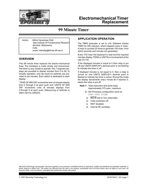
<strong>Electromechanical</strong> <strong>Timer</strong> <strong>Replacement</strong>APPENDIX A:SOURCE CODE; define ram ports and data ; ************************* ;DEFINE PORT; ***********;DEFINE PORTS;************gp0 equ 0gp1 equ 1gp2 equ 2gp3 equ 3gp4 equ 4gp5 equ 5;DISPLAY PORT;************disp_data equ gp0disp_clk equ gp1disp_strobe equ gp2;KEYBOARD PORT;*************;units_key equ gp3;tens_key equ gp4;RELAY PORT;**********relay equ gp5;*******************************************************;DEFINE RAMunits equ 08h ;minutes unit displaytens equ units+1 ;minutes tens displaycounter_4ms equ tens+1 ;incremented every 4 mseccounter_100ms equ counter_4ms+1 ;incremented every 100 msecseconds equ counter_100ms+1oldkey equ seconds+1 ;for key debouncingnewkey equ oldkey+1 ;-------- ,, ------key equ newkey+1 ;key pressed datadigit_inc equ key+1 ;inc units display if bo = 1;inc tens display if b1 = 1tmr_comp equ digit_inc+1 ;tmr0 comparator registerscrtch0 equ tmr_comp+1scrtch1 equ scrtch0+1scrtch2 equ scrtch1+1;*******************************************************;DEFINE FLAGS AND BITSb0 equ 0b1 equ 1b2 equ 2b3 equ 3b4 equ 4b5 equ 5b6 equ 6b7 equ 7;key;***; equ b0; equ b1; equ b2units_key equ b3tens_key equ b4; equ b5; equ b6; equ b7;digit_inc;*********units_inc equ b0tens_inc equ b1; equ b2© 1997 Microchip Technology Inc. DS40160A/1_001-page 3
<strong>Electromechanical</strong> <strong>Timer</strong> <strong>Replacement</strong>; equ b3; equ b4; equ b5; equ b6; equ b7;******************************************#define data_hi bsf GPIO, disp_data#define data_lo bcf GPIO, disp_data#define clk_hi bsf GPIO, disp_clk#define clk_lo bcf GPIO, disp_clk#define strobe_hi bsf GPIO, disp_strobe#define strobe_lo bcf GPIO, disp_strobe#define relay_on bsf GPIO, relay#define relay_off bcf GPIO, relay;************** EOF DEF_RAM.ASM ***********; SUBS.ASM; ********;read key port in keyread_keys movf newkey, w ;debouncing taken care by s/wmovwf oldkeymovf GPIO, w ;read newkeysandlw 00011000b ;gp3, gp4 are key portsmovwf newkeycomf newkey, f ;complement since active lowandwf oldkey, w ;key=oldkey AND compl(newkey)movwf key;indicate to display routine units or tens key pressedbtfsc key, units_keybsf digit_inc, units_incbtfsc key, tens_keybsf digit_inc, tens_increturn;************************************************************init_ports movlw 0 ;all lomovwf GPIOmovlw 00011000b ;port g0-g2,g5 o/p & gp3,gp4 i/ptris GPIOclrf TMR0 ;clr tmr0 & prescalermovlw 11000011b ;tmr0 enable with 1:16 prescaleroptionreturn;***************** EOF SUBS.ASM ******************************; TABLES.ASM; **********;7 segments decoded data. lo is segment on & hi is segment offget_seg addwf PCL, f; ABCDEFGP ;P is decimal pointretlw 00000011b ;0retlw 10011111b ;1retlw 00100101b ;2retlw 00001101b ;3retlw 10011001b ;4retlw 01001001b ;5retlw 01000001b ;6retlw 00011111b ;7retlw 00000001b ;8retlw 00011001b ;9dec_pt equ 11111110b ;decimal point bit;*************** EOF TABLES.ASM **************************DS40160A/1_001-page 4© 1997 Microchip Technology Inc.
<strong>Electromechanical</strong> <strong>Timer</strong> <strong>Replacement</strong>Two switches allow selection of four darkness durations:7.0 hours=1,512,000sixty hertz tics (171240 hex)7.5 hours=1,620,000sixty hertz tics (18b820 hex)8.0 hours=1,728,000sixty hertz tics (1A5E00 hex)8.5 hours=1,836,000sixty hertz tics (1C03E0 hex)These hex values are loaded into 3 bytes of RAM andare decremented at each 60 Hz tic interval.The enable flag prevents the lamp from being turnedoff. When it is still dark, nighttime after the requiredinterval of darkness has elapsed.FIGURE 2:SCHEMATIC DIAGRAM POULTRY DARKNESS CONTROLLER+5V+5V Regulator78L05+5V+5VAmbient LightSense31PIC12C50867Dip SwitchInterval Select560 Hz Sense8120V ACLamp+5VAKDS40160A/1_008-page 1-2© 1997 Microchip Technology Inc.
MWORLDWIDE SALES & SERVICEAMERICASCorporate OfficeMicrochip Technology Inc.2355 West Chandler Blvd.Chandler, AZ 85224-6199Tel: 602-786-7200 Fax: 602-786-7277Technical Support: 602 786-7627Web: http://www.microchip.comAtlantaMicrochip Technology Inc.500 Sugar Mill Road, Suite 200BAtlanta, GA 30350Tel: 770-640-0034 Fax: 770-640-0307BostonMicrochip Technology Inc.5 Mount Royal AvenueMarlborough, MA 01752Tel: 508-480-9990 Fax: 508-480-8575ChicagoMicrochip Technology Inc.333 Pierce Road, Suite 180Itasca, IL 60143Tel: 630-285-0071 Fax: 630-285-0075DallasMicrochip Technology Inc.14651 Dallas Parkway, Suite 816Dallas, TX 75240-8809Tel: 972-991-7177 Fax: 972-991-8588DaytonMicrochip Technology Inc.Two Prestige Place, Suite 150Miamisburg, OH 45342Tel: 937-291-1654 Fax: 937-291-9175Los AngelesMicrochip Technology Inc.18201 Von Karman, Suite 1090Irvine, CA 92612Tel: 714-263-1888 Fax: 714-263-1338New YorkMicrochip Technology Inc.150 Motor Parkway, Suite 416Hauppauge, NY 11788Tel: 516-273-5305 Fax: 516-273-5335San JoseMicrochip Technology Inc.2107 North First Street, Suite 590San Jose, CA 95131Tel: 408-436-7950 Fax: 408-436-7955TorontoMicrochip Technology Inc.5925 Airport Road, Suite 200Mississauga, Ontario L4V 1W1, CanadaTel: 905-405-6279 Fax: 905-405-6253ASIA/PACIFICHong KongMicrochip Asia PacificRM 3801B, Tower TwoMetroplaza223 Hing Fong RoadKwai Fong, N.T., Hong KongTel: 852-2-401-1200 Fax: 852-2-401-3431IndiaMicrochip Technology Inc.India Liaison OfficeNo. 6, Legacy, Convent RoadBangalore 560 025, IndiaTel: 91-80-229-4036 Fax: 91-80-559-9840KoreaMicrochip Technology Korea168-1, Youngbo Bldg. 3 FloorSamsung-Dong, Kangnam-KuSeoul, KoreaTel: 82-2-554-7200 Fax: 82-2-558-5934ShanghaiMicrochip TechnologyRM 406 Shanghai Golden Bridge Bldg.2077 Yan’an Road West, Hong Qiao DistrictShanghai, PRC 200335Tel: 86-21-6275-5700Fax: 86 21-6275-5060SingaporeMicrochip Technology TaiwanSingapore Branch200 Middle Road#10-03 Prime CentreSingapore 188980Tel: 65-334-8870 Fax: 65-334-8850Taiwan, R.O.CMicrochip Technology Taiwan10F-1C 207Tung Hua North RoadTaipei, Taiwan, ROCTel: 886 2-717-7175 Fax: 886-2-545-0139EUROPEUnited KingdomArizona Microchip Technology Ltd.Unit 6, The CourtyardMeadow Bank, Furlong RoadBourne End, Buckinghamshire SL8 5AJTel: 44-1628-851077 Fax: 44-1628-850259FranceArizona Microchip Technology SARLZone Industrielle de la Bonde2 Rue du Buisson aux Fraises91300 Massy, FranceTel: 33-1-69-53-63-20 Fax: 33-1-69-30-90-79GermanyArizona Microchip Technology GmbHGustav-Heinemann-Ring 125D-81739 Müchen, GermanyTel: 49-89-627-144 0 Fax: 49-89-627-144-44ItalyArizona Microchip Technology SRLCentro Direzionale ColleoniPalazzo Taurus 1 V. Le Colleoni 120041 Agrate BrianzaMilan, ItalyTel: 39-39-6899939 Fax: 39-39-6899883JAPANMicrochip Technology Intl. Inc.Benex S-1 6F3-18-20, ShinyokohamaKohoku-Ku, Yokohama-shiKanagawa 222 JapanTel: 81-45-471- 6166 Fax: 81-45-471-61227/29/97All rights reserved. ©1997, Microchip Technology Incorporated, USA. 8/97Printed on recycled paper.Information contained in this publication regarding device applications and the like is intended for suggestion only and may be superseded by updates. No representation orwarranty is given and no liability is assumed by Microchip Technology Incorporated with respect to the accuracy or use of such information, or infringement of patents or otherintellectual property rights arising from such use or otherwise. Use of Microchip’s products as critical components in life support systems is not authorized except with expresswritten approval by Microchip. No licenses are conveyed, implicitly or otherwise, under any intellectual property rights. The Microchip logo and name are registered trademarksof Microchip Technology Inc. in the U.S.A. and other countries. All rights reserved. All other trademarks mentioned herein are the property of their respective companies.40160A/1_008-page 4© 1997 Microchip Technology Inc.
<strong>Electromechanical</strong> <strong>Timer</strong><strong>Replacement</strong>Lawn Sprinkler System Using a PIC12C508Author:Aroldo CarvalhoBoca Raton, FLUSAemail: aroldo@gate.netAPPLICATION OPERATIONThis Lawn Sprinkler System is an electronic timer thatcan be programmed to activate and deactivate thesprinkler electric valve.You can program it to activate anytime up to fifteendays, with 1 to 15 minutes for each sprinkler circuit. Thesprinkler circuits will vary depending on the lawninstallation. The number of sprinkler circuits areprogrammable.There will also be a bypass switch that will allow theuser to activate the electric valve bypassing theelectronic circuit at any time.To improve the system a backup battery would hold thedata in case of a power failure.OPERATIONThe user has an LCD Display and three push buttons toprogram the unit as shown in Figure 1.FIGURE 1:SIMPLE DIAGRAMLCD DisplayDay Hour Minute1. Set the number of sprinkler circuits.pushbuttonsTo set the number of sprinkler circuits, press andhold the day and hour buttons together, thenpress the minute button to select from 1 to 8 circuits.2. Select the day, the start and end time for eachsprinkler circuit.Press the day button to scroll from 1 to 15, thenpress the hour and minute buttons to select thedesired sprinkler circuit. Then enter start hourand minute and stop minute. The duration can befrom 1 to 20 minutes per sprinkler circuit.Repeat the above steps for each circuit.Microchip Technology Incorporated, has been granted a non-exclusive, worldwide license to reproduce, publish and distribute all submitted materials, ineither original or edited form. The author has affirmed that this work is an original, unpublished work and that he/she owns all rights to such work. Allproperty rights, such as patents, copyrights and trademarks remain with author.© 1997 Microchip Technology Inc. DS40160A/1_004-page 1
<strong>Electromechanical</strong> <strong>Timer</strong> <strong>Replacement</strong>THE SOFTWAREThe software consists of a timer that will count seconds,minutes, hours and days up to fifteen days. After that itwill start the first day again and so on. It then checks theactivation/deactivation table and will turn on the relay,through GP5 output, for the amount of time programmedfor each sprinkler circuit. The switching of thesprinkler system happens outside in the sprinkler gearusing the water flow.The pushbuttons are read by the software and will displaythe corresponding message depending on whichbutton was pressed.This is a low cost sprinkler system, it consists of the followingcomponents:1. PIC12C5082. 3 Push buttons3. 6 Pull-up resistors (10 kOhms)4. Serial LCD Display (2 Rows x 16 Columns)5. NPN Transistor6. Relay7. 5 Volt Regulator8. Wall Transformer (Input 110 VAC, output9 VDC).9. Diode10. Bypass Switch.FIGURE 2:SCHEMATIC+5VPull-upPull-up5 VDCRegulatorPIC12C508GP0GP1ClockDataLCD Display2x16+5VGP2Pull-up Pull-up Pull-upGP3DayHourGP4GP5Minutes+5VN.C.To ElectricValveN.O.C.DS40160A/1_004-page 2© 1997 Microchip Technology Inc.
MWORLDWIDE SALES & SERVICEAMERICASCorporate OfficeMicrochip Technology Inc.2355 West Chandler Blvd.Chandler, AZ 85224-6199Tel: 602-786-7200 Fax: 602-786-7277Technical Support: 602 786-7627Web: http://www.microchip.comAtlantaMicrochip Technology Inc.500 Sugar Mill Road, Suite 200BAtlanta, GA 30350Tel: 770-640-0034 Fax: 770-640-0307BostonMicrochip Technology Inc.5 Mount Royal AvenueMarlborough, MA 01752Tel: 508-480-9990 Fax: 508-480-8575ChicagoMicrochip Technology Inc.333 Pierce Road, Suite 180Itasca, IL 60143Tel: 630-285-0071 Fax: 630-285-0075DallasMicrochip Technology Inc.14651 Dallas Parkway, Suite 816Dallas, TX 75240-8809Tel: 972-991-7177 Fax: 972-991-8588DaytonMicrochip Technology Inc.Two Prestige Place, Suite 150Miamisburg, OH 45342Tel: 937-291-1654 Fax: 937-291-9175Los AngelesMicrochip Technology Inc.18201 Von Karman, Suite 1090Irvine, CA 92612Tel: 714-263-1888 Fax: 714-263-1338New YorkMicrochip Technology Inc.150 Motor Parkway, Suite 416Hauppauge, NY 11788Tel: 516-273-5305 Fax: 516-273-5335San JoseMicrochip Technology Inc.2107 North First Street, Suite 590San Jose, CA 95131Tel: 408-436-7950 Fax: 408-436-7955TorontoMicrochip Technology Inc.5925 Airport Road, Suite 200Mississauga, Ontario L4V 1W1, CanadaTel: 905-405-6279 Fax: 905-405-6253ASIA/PACIFICHong KongMicrochip Asia PacificRM 3801B, Tower TwoMetroplaza223 Hing Fong RoadKwai Fong, N.T., Hong KongTel: 852-2-401-1200 Fax: 852-2-401-3431IndiaMicrochip Technology Inc.India Liaison OfficeNo. 6, Legacy, Convent RoadBangalore 560 025, IndiaTel: 91-80-229-4036 Fax: 91-80-559-9840KoreaMicrochip Technology Korea168-1, Youngbo Bldg. 3 FloorSamsung-Dong, Kangnam-KuSeoul, KoreaTel: 82-2-554-7200 Fax: 82-2-558-5934ShanghaiMicrochip TechnologyRM 406 Shanghai Golden Bridge Bldg.2077 Yan’an Road West, Hong Qiao DistrictShanghai, PRC 200335Tel: 86-21-6275-5700Fax: 86 21-6275-5060SingaporeMicrochip Technology TaiwanSingapore Branch200 Middle Road#10-03 Prime CentreSingapore 188980Tel: 65-334-8870 Fax: 65-334-8850Taiwan, R.O.CMicrochip Technology Taiwan10F-1C 207Tung Hua North RoadTaipei, Taiwan, ROCTel: 886 2-717-7175 Fax: 886-2-545-0139EUROPEUnited KingdomArizona Microchip Technology Ltd.Unit 6, The CourtyardMeadow Bank, Furlong RoadBourne End, Buckinghamshire SL8 5AJTel: 44-1628-851077 Fax: 44-1628-850259FranceArizona Microchip Technology SARLZone Industrielle de la Bonde2 Rue du Buisson aux Fraises91300 Massy, FranceTel: 33-1-69-53-63-20 Fax: 33-1-69-30-90-79GermanyArizona Microchip Technology GmbHGustav-Heinemann-Ring 125D-81739 Müchen, GermanyTel: 49-89-627-144 0 Fax: 49-89-627-144-44ItalyArizona Microchip Technology SRLCentro Direzionale ColleoniPalazzo Taurus 1 V. Le Colleoni 120041 Agrate BrianzaMilan, ItalyTel: 39-39-6899939 Fax: 39-39-6899883JAPANMicrochip Technology Intl. Inc.Benex S-1 6F3-18-20, ShinyokohamaKohoku-Ku, Yokohama-shiKanagawa 222 JapanTel: 81-45-471- 6166 Fax: 81-45-471-61227/29/97All rights reserved. ©1997, Microchip Technology Incorporated, USA. 8/97Printed on recycled paper.Information contained in this publication regarding device applications and the like is intended for suggestion only and may be superseded by updates. No representation orwarranty is given and no liability is assumed by Microchip Technology Incorporated with respect to the accuracy or use of such information, or infringement of patents or otherintellectual property rights arising from such use or otherwise. Use of Microchip’s products as critical components in life support systems is not authorized except with expresswritten approval by Microchip. No licenses are conveyed, implicitly or otherwise, under any intellectual property rights. The Microchip logo and name are registered trademarksof Microchip Technology Inc. in the U.S.A. and other countries. All rights reserved. All other trademarks mentioned herein are the property of their respective companies.40160A/1_004-page 4© 1997 Microchip Technology Inc.
Maxi Functions, Micro Chip<strong>Electromechanical</strong> <strong>Timer</strong><strong>Replacement</strong>sAuthor:DESCRIPTIONMark WalkerCircuit Graphics, Inc.Hillsboro, ORUSAemail: mmwatcgi@aracnet.comThis circuit allows fodder for several discussions,including efficient methods of using pins. A simple wayto sense buttons with fewer pins than the classic crossgridarray does is one obvious derivative (5-lines for 8push button, etc.). It also emphasizes the current drivingcapabilities of the MIcrochip family of parts in a funenvironment.The application contains the kernel for several cleverapproaches for maximizing the use of the 8-pin family(even more can be done with A/D parts). It uses two 7-segment LED digits, a piezo noise maker and two pushbutton to construct a simple game timer, and can bebuilt with a minimum of components (could even beused like an alarm). This application shows how to drive14 segments, a speaker and two push button with this8-pin low-cost part.To simplify understanding of the schematic, the displaysare common anode type, and must have thedriven cathode pulled low before the anode pin is pulledhigh to light any segment. The speaker is driven with allother pins low, and sleep is with all outputs low. The circuitis designed for 3 volts, and either push buttonshould wake it from sleep.The functions mentioned on the schematic include acountdown timer, where the second button can start orstop the countdown, and a dark countdown timer,where the second button only starts the timer, with novisual hint as to when the time will run out (adds spiceto some games). The minutes and seconds can be setand will be remembered between uses, until new valuesare entered. 9 minutes was selected as the maximumon that range because of the game nature of thecircuit, and the less than perfect accuracy of the internalclock. 99 seconds was selected as a maximum on theset seconds function to maximize the functionality, soover 10 and a half minutes maximum is available. Thedice mode is added for utility, and rolls new numbersevery time the second button is pressed, (after a fewbeeps from the speaker) with first one digit popping upand then the other. The system goes to sleep after a bitof non-use and wakes up in the same place on anypush. The OFF mode (OF) forces the unit to sleep withany button waking up and the unit starting at the top ofthe list.Microchip Technology Incorporated, has been granted a non-exclusive, worldwide license to reproduce, publish and distribute all submitted materials, ineither original or edited form. The author has affirmed that this work is an original, unpublished work and that he/she owns all rights to such work. Allproperty rights, such as patents, copyrights and trademarks remain with author.© 1997 Microchip Technology Inc. DS40160A/1_010-page 1
<strong>Electromechanical</strong> <strong>Timer</strong> <strong>Replacement</strong>sFIGURE 1:PIC12C508 GAME TIMER SCHEMATICD1 Protection (Optional)4001BT1 3VC2 220 µf (Optional)C1 0.1U11234VDDGP5GP4MCLR/GP3VSSGP0GP1GP2/T08765PIC12C5081 DSP11 0 LTS360aa2 f b 9f b3 g g4 e c 8e cd 7d5611 0aa2 f b 9f b3 g g4 e c 8e cd 7d DSP25 6 LTS360RP1D2.2k2.2kQ1NPNPush buttonS22.2kQ1NPNS1FunctionFunctionDisplayEnterEnter2.2kQ1NPNCountdown <strong>Timer</strong> dn STARTS/STOPSDark Countdown dr STARTSSet Minutes Sn 0 - 9Set Seconds SS 0 - 99DICE di ROLLSPower Off OF (any push button wakes up)DS40160A/1_010-page 2© 1997 Microchip Technology Inc.
MWORLDWIDE SALES & SERVICEAMERICASCorporate OfficeMicrochip Technology Inc.2355 West Chandler Blvd.Chandler, AZ 85224-6199Tel: 602-786-7200 Fax: 602-786-7277Technical Support: 602 786-7627Web: http://www.microchip.comAtlantaMicrochip Technology Inc.500 Sugar Mill Road, Suite 200BAtlanta, GA 30350Tel: 770-640-0034 Fax: 770-640-0307BostonMicrochip Technology Inc.5 Mount Royal AvenueMarlborough, MA 01752Tel: 508-480-9990 Fax: 508-480-8575ChicagoMicrochip Technology Inc.333 Pierce Road, Suite 180Itasca, IL 60143Tel: 630-285-0071 Fax: 630-285-0075DallasMicrochip Technology Inc.14651 Dallas Parkway, Suite 816Dallas, TX 75240-8809Tel: 972-991-7177 Fax: 972-991-8588DaytonMicrochip Technology Inc.Two Prestige Place, Suite 150Miamisburg, OH 45342Tel: 937-291-1654 Fax: 937-291-9175Los AngelesMicrochip Technology Inc.18201 Von Karman, Suite 1090Irvine, CA 92612Tel: 714-263-1888 Fax: 714-263-1338New YorkMicrochip Technology Inc.150 Motor Parkway, Suite 416Hauppauge, NY 11788Tel: 516-273-5305 Fax: 516-273-5335San JoseMicrochip Technology Inc.2107 North First Street, Suite 590San Jose, CA 95131Tel: 408-436-7950 Fax: 408-436-7955TorontoMicrochip Technology Inc.5925 Airport Road, Suite 200Mississauga, Ontario L4V 1W1, CanadaTel: 905-405-6279 Fax: 905-405-6253ASIA/PACIFICHong KongMicrochip Asia PacificRM 3801B, Tower TwoMetroplaza223 Hing Fong RoadKwai Fong, N.T., Hong KongTel: 852-2-401-1200 Fax: 852-2-401-3431IndiaMicrochip Technology Inc.India Liaison OfficeNo. 6, Legacy, Convent RoadBangalore 560 025, IndiaTel: 91-80-229-4036 Fax: 91-80-559-9840KoreaMicrochip Technology Korea168-1, Youngbo Bldg. 3 FloorSamsung-Dong, Kangnam-KuSeoul, KoreaTel: 82-2-554-7200 Fax: 82-2-558-5934ShanghaiMicrochip TechnologyRM 406 Shanghai Golden Bridge Bldg.2077 Yan’an Road West, Hong Qiao DistrictShanghai, PRC 200335Tel: 86-21-6275-5700Fax: 86 21-6275-5060SingaporeMicrochip Technology TaiwanSingapore Branch200 Middle Road#10-03 Prime CentreSingapore 188980Tel: 65-334-8870 Fax: 65-334-8850Taiwan, R.O.CMicrochip Technology Taiwan10F-1C 207Tung Hua North RoadTaipei, Taiwan, ROCTel: 886 2-717-7175 Fax: 886-2-545-0139EUROPEUnited KingdomArizona Microchip Technology Ltd.Unit 6, The CourtyardMeadow Bank, Furlong RoadBourne End, Buckinghamshire SL8 5AJTel: 44-1628-851077 Fax: 44-1628-850259FranceArizona Microchip Technology SARLZone Industrielle de la Bonde2 Rue du Buisson aux Fraises91300 Massy, FranceTel: 33-1-69-53-63-20 Fax: 33-1-69-30-90-79GermanyArizona Microchip Technology GmbHGustav-Heinemann-Ring 125D-81739 Müchen, GermanyTel: 49-89-627-144 0 Fax: 49-89-627-144-44ItalyArizona Microchip Technology SRLCentro Direzionale ColleoniPalazzo Taurus 1 V. Le Colleoni 120041 Agrate BrianzaMilan, ItalyTel: 39-39-6899939 Fax: 39-39-6899883JAPANMicrochip Technology Intl. Inc.Benex S-1 6F3-18-20, ShinyokohamaKohoku-Ku, Yokohama-shiKanagawa 222 JapanTel: 81-45-471- 6166 Fax: 81-45-471-61227/29/97All rights reserved. ©1997, Microchip Technology Incorporated, USA. 8/97Printed on recycled paper.Information contained in this publication regarding device applications and the like is intended for suggestion only and may be superseded by updates. No representation orwarranty is given and no liability is assumed by Microchip Technology Incorporated with respect to the accuracy or use of such information, or infringement of patents or otherintellectual property rights arising from such use or otherwise. Use of Microchip’s products as critical components in life support systems is not authorized except with expresswritten approval by Microchip. No licenses are conveyed, implicitly or otherwise, under any intellectual property rights. The Microchip logo and name are registered trademarksof Microchip Technology Inc. in the U.S.A. and other countries. All rights reserved. All other trademarks mentioned herein are the property of their respective companies.40160A/1_010-page 4© 1997 Microchip Technology Inc.
PIC12C508 Based <strong>Timer</strong><strong>Electromechanical</strong> <strong>Timer</strong><strong>Replacement</strong>Author:DESCRIPTIONRavi PailoorChip TechnologiesBangalore, India1. CONFIGURATION OF THE PIC12C508.a) Pin 2 - input for configuration.b) Pin 3 - output for software PWM generation.c) Pin 4 - input for start/stop switch.d) Pin 5 - input for 50 Hz time-base.e) Pin 6 - output for relay driving.f) Pin 7 - input for comparator input.2. POWER SUPPLY.Transformer T1, Diodes D1, D2, and D3 with C1,C2, C3, and U3 form the power supply giving 5volts to the relay and the I.C.s. A transformerlesspower supply can be used if isolation is required.3. TIME-BASETo generate a time-base for the timer, the secondopamp, U2B, is used to generate a square wave of50 Hz. Alternatively, a resistor and a zener diodecan be used for generating a near square wave.Even the internal clocking can be used for the timebase.4. CONFIGURATIONJumper J3 is used to select the range of the timebase.If J3 is open, 0 to 100 second range isselected and if closed 0 to 100 minutes range isselected.5. START/STOPSwitch S1 will start the timing and also stop thetimer is required.6. COMPARISONThe PIC12C508 will generate PWM which is filteredto generate an analog signal. Double filteringcan be used for a smoother waveform. This signalis fed to the inverting I/P of the opamp (LM358used as the comparator). It is then compared to thesignal at the non-inverting input. The signal (0 - 5Vvia potentiometer R5 and resistor R4) to the noninvertinginput is proportional to the timingrequired.7. OUTPUTThe SPDT relay is driven by the PIC12C508 ontime-out.OPERATIONOn power up the timer goes to standby mode. The timeis selected by R5. The range depends on the selectionof J3 as explained previously. Once the time is set, theSTART/STOP button is pressed to start the timing. ThePIC12C508 will generate a PWM signal at a ratio of1:258 (8-bits) and poll pin 7 for a change of state. Ondetecting the change, the timing is scaled as follows:256 bits = 100 seconds or minutesn bits = (n x 100)/256 seconds or minutesAfter calculation the relay will be switched on and thetimer will start timing out. The 50 Hz input is taken asthe time-base and the timer will de-energize the relayon time-out and go to standby mode. At any given time,pressing switch S1 will stop the timer.Notes:1. Software generation of PWM and converting toanalog will not give 5 volts due to attenuation.Hence the POT setting has to be limited to thegenerated voltage or the analog voltage willhave to be amplified to 5 volts. This voltage willhave to be proportional from 0 to 256 bits.2. Internal or mains based timing is as accurate ascrystal based timing.3. Transformer based power supply is not costeffective but used mainly for isolation.4. U2B for 50 Hz squaring is used because LM358has dual opamp and only one is required forcomparing.Microchip Technology Incorporated, has been granted a non-exclusive, worldwide license to reproduce, publish and distribute all submitted materials, ineither original or edited form. The author has affirmed that this work is an original, unpublished work and that he/she owns all rights to such work. Allproperty rights, such as patents, copyrights and trademarks remain with author.© 1997 Microchip Technology Inc. DS40160A/1_009-page 1
<strong>Electromechanical</strong> <strong>Timer</strong> <strong>Replacement</strong>FIGURE 1:SCHEMATICR1R2VCCC41824VCCGNDSELS/SU1RLYCINPWM50 Hz6735U2A1R332C5R42VCC3R5PIC12C508ComparingTime SettingJ3VccS112R6R956R8U2B7R7VccK1J1123START/STOPQ1Time-base GeneratorRelay OutputVccJ21T1D1D3U3I78L05G O23D2C1 C2 C3Power SupplyDS40160A/1_009-page 2© 1997 Microchip Technology Inc.
<strong>Electromechanical</strong> <strong>Timer</strong><strong>Replacement</strong>A Simple Programmable <strong>Timer</strong> with Time Correction CircuitAuthor: Kirill Yelizarov V.Moscow Power EngineeringInstituteMoscow, Russiaemail: tihonov@srv-OVERVIEWThe timer discussed in this application note may beused to operate different appliances using AC or DCvoltage (battery powered equipment). It is adjustablefrom 1 second to 99 hours, 59 minutes, 59 seconds andhas a time correction circuit to adjust the accuracy ofthe internal 4 MHz RC oscillator. It is based on thePIC12C508 microcontroller and requires few externalcomponents.The system block diagram is shown in Figure 1. Thetimer has 3 buttons, an LCD panel, and a power switch.The power switch, in the position shown in Figure 1, willactivate the timer, and in the other position the load willbe connected directly to the line out, thus switching offthe opto-transformer to prevent accumulator overcharge.When switched off, the timer is still operationaland may be set. To reduce power consumption, thetimer goes to sleep (LCD panel appears blank) in 15seconds after the last button depression, while in editmode.FIGURE 1:SYSTEM BLOCK DIAGRAMThe first keyboard button is “Change Digit.” This buttonis used to position the cursor to the desired digit. Thecursor moves clockwise from the lower seconds digit tothe higher hours digit. Separators are skipped. The secondbutton is “Increase Value.” With each depression ofthis button the digit value is increased. After 9 pressesthe value rolls over to 0. The third button is “Start/Stop.”This button is used to edit data and to activate the timer.When run in edit mode, with the earlier specified buttons,data may be entered. Once the Start/Stop buttonis pressed, the timer is activated. It stops if the timeexpires or the Start/Stop button is pressed again (inboth cases this will affect the load). In any case, if thetimer is stopped, then the edit mode becomes activeand the remaining data may be edited.This appliance may be used as a simple timer and ifused with a normally closed contact opto-relay, it mayturn on any load when the time expires.Use an 8-pin socket for the PIC12C508 JW devicebecause it needs to be programmed before putting it inthe circuit. The board has three buttons (S1, S2, S3),capacitor (C2), resistor (R1), and an LED (instead of anopto-relay).The opto-relay may be replaced with an opto-triac (ACoperation only). Using a triac or an ordinary mechanicalrelay with an opto-relay or an opto-triac will power-upthe output (DS00559). The opto-relay may be replacedwith an ordinary mechanical relay, but most of themneed a higher voltage and a transistor amplifier to activatetheir coil.Line InPowerSwitchOpto-relayLine OutKeyboardPowerPIC12C508LCDNeutral InNeutral OutMicrochip Technology Incorporated, has been granted a non-exclusive, worldwide license to reproduce, publish and distribute all submitted materials, ineither original or edited form. The author has affirmed that this work is an original, unpublished work and that he/she owns all rights to such work. Allproperty rights, such as patents, copyrights and trademarks remain with author.© 1997 Microchip Technology Inc. DS40160A/1_002-page 1
<strong>Electromechanical</strong> <strong>Timer</strong> <strong>Replacement</strong>HARDWAREThe schematic diagram is shown in Figure 2.FIGURE 2:SCHEMATIC DIAGRAMC1C2BatteryD1D2D3D4D5D6D1D2D3D4D5D6R2C3D13R3C4S4Line InNeutral InNeutral OutS1S2S31 U1VDD 57 GP2GP0PIC12C5086GP1 2GP54GP3 GP43Vss8R1ClockDataOpto-RelayDisplayLine OutNote 1: GND symbol is circuit common; it is not tied to AC ground.2: In case of DC input voltage, C4 should be replaced with a resistor to limit current flow through the LEDs(R3 may be removed).3: If the input voltage is 36V or less, the opto-transformer may be removed.4: DISPLAY means AY0438 IC with LCD panel added.5: A FUSE is required in-Line In-circuit.The <strong>Timer</strong> Parts ListCapacitors:C1, C3 = 47 µF electrolyticC2C4Diodes:D1 – D6D7 – D12D13Resistors:R1= 0.1 µF ceramic= 1 µF (depends on the current flowlimits through LEDs)= Any type IR photo diodes= Any type IR light emitting diodes= 1N4001 general purpose 1A rectifier= Depends on the type of opto-relay:VOVLEDILED= PICmicro output low voltage(0.6V max)= Input opto-relay IR LEDvoltage (0.8V typical)= LED current (10 mA typical)3 – VLED – VoR1 = ----------------------------------- = 160ΩILEDR2R3Miscellaneous:= 100Ω (depends on the current flowlimits through transformer LEDs andoutput voltage of photo diodes batteryto provide minimal charge current forthe battery)= 1 MΩ, used to discharge capacitor C4Battery = 3V AccumulatorOpto-relay = Any opto-relay or opto-triac matchingabove specified requirementsS1 – S3 = Normally open push button switchesS4 = Two position switchU1 = PIC12C508 programmed withMy<strong>Timer</strong> codeMICROCHIP TOOLS USEDAssembler/Compiler Version:MPASM version 1.40DS40160A/1_002-page 2© 1997 Microchip Technology Inc.
<strong>Electromechanical</strong> <strong>Timer</strong> <strong>Replacement</strong>APPENDIX A:SOURCE CODE;A Simple <strong>Timer</strong> with Time Correction Circuit;Author: Kirill YelizarovLISTINCLUDEP=PIC12C508, R=DEC__CONFIG _HS_OSC & _WDT_OFF & _CP_OFF & _MCLRE_OFF; ------------ D A T A ------------<strong>Timer</strong>Status equ 0x07 ;<strong>Timer</strong> status flagsSecondsLow equ 0x08 ;Seconds low digitSecondsHigh equ 0x09 ;Seconds high digitMS_Separator equ 0x0a ;Minutes/Seconds separatorMinuteLow equ 0x0b ;Minutes low digitMinuteHigh equ 0x0c ;Minutes high digitHM_Separator equ 0x0d ;Hours/Minutes separatorHourLow equ 0x0e ;Hours low digitHourHigh equ 0x0f ;Hours high digit<strong>Timer</strong>Count equ 0x10 ;<strong>Timer</strong> countDigit equ 0x11 ;Used in ShowDigit to send data using RRF commandCount equ 0x12 ;Multipurpose countTimePatch equ 0x13TimeCorrection equ 0x14; ------------ <strong>Timer</strong> Status Flags ------------SleepFlag equ 7 ;If set then the sleep command is activatedSetTimeFlag equ 6 ;Flag is raised when it's time to update timeStartStopFlag equ 5 ;If raised the timer runs else it may be edited<strong>Timer</strong>Flag equ 4 ;this flag is raised when TMR0 seventh bit is set; equ 3; equ 2; equ 1; equ 0; ------------ KeyBoard & LCD hardware bits ------------LCD_Clock equ 5 ;LCD clockLCD_Data equ 4 ;LCD dataStartStop equ 3 ;Start/Stop buttonRelay equ 2 ;RelayIncValue equ 1 ;Increase digit value buttonNextDigit equ 0 ;Set next digit button; ------------ C O D E ------------org 0clrf <strong>Timer</strong>Status ;Reset all flagsgoto Reset<strong>Timer</strong> ;Reset timer and read time correction value; ------------ T A B L E S ------------;Decode data to 8 segment LCDDecodeValueaddwfPCL,Fretlw b'00111111' ;0retlw b'00000110' ;1retlw b'01011011' ;2retlw b'01001111' ;3retlw b'01100110' ;4retlw b'01101101' ;5retlw b'01111101' ;6retlw b'00000111' ;7© 1997 Microchip Technology Inc. DS40160A/1_002-page 3
<strong>Electromechanical</strong> <strong>Timer</strong> <strong>Replacement</strong>retlw b'01111111' ;8retlw b'01101111' ;9retlw b'00000000' ;blankretlw b'01000000' ;hours/minutes separatorretlw b'01000000' ;minutes/seconds separatorretlw b'00001000' ;cursor;Time correction table;In correction mode the timer outputs 250 kHz signal on pin LCD_clock;This may be tested and a new correction value be programmed;If bit is zeroed then the next value is fetched (because 1’s may be programmed many times)TimeCorrectionTableaddwfPCL,F;bit 1 = Correction mode;bit 1 = Read this value;bits Time correction value; 0 = Normal timer operation; 0 = Skip this valueretlw b'11000111' ; Set time correction value to 7retlwb'11111111'retlwb'11111111'retlwb'11111111'retlwb'11111111'retlwb'11111111'retlwb'11111111'retlwb'11111111'retlwb'11111111'retlwb'11111111'; ------------ S U B R O U T I N E S ----------;Send timer data from lowest digit to the highest including separators to AY0438ShowTimebcf <strong>Timer</strong>Status,SetTimeFlag ;reset SetTimeFlag bitmovlw0x0amovwf FSR ;get first digit (seconds low)ShowNextDigit:movfINDF,WcallDecodeValuebtfsc <strong>Timer</strong>Status,SleepFlag ;If Sleep mode activatedmovlw 0x10 ;then set display blankcallShowDigitincf FSR,F ;get next digitbtfss FSR,4 ;terminate if the 4th bit is setgoto ShowNextDigit ;(You should not move timer data in RAMreturn;for this function to work properly);Transmit one digit data to AY0438 (see PIC16/17 Microcontroller Data Book 95/96 AY0438 page 4-6);Load input should be tied highShowDigitmovwf Digit ;Save current digit valuemovlw0x08movwf Count ;Set Count to 8 (8 segment LCD)NextBit:bcf GPIO,LCD_Data ;clear Data bitrrfDigit,Fbtfsc STATUS,C ;If bit is clear then skipbsf GPIO,LCD_Data ;Else set Data bitbsf GPIO,LCD_Clock ;Toggle Clock, the data to be read by AY0438bcfGPIO,LCD_Clockdecfsz Count,FgotoNextBitreturn;Get current time from TMR0GetTimeDS40160A/1_002-page 4© 1997 Microchip Technology Inc.
<strong>Electromechanical</strong> <strong>Timer</strong> <strong>Replacement</strong>btfss TMR0,7 atch for the TMR0 seventh bit getting setreturnbtfsc <strong>Timer</strong>Status,<strong>Timer</strong>Flag ;and <strong>Timer</strong>Flag is not setreturnbsf <strong>Timer</strong>Status,<strong>Timer</strong>Flag ;then set this flag, this will prevent from coming;here again till the seventh bit is reset and set againdecfsz <strong>Timer</strong>Count,Freturnbsf<strong>Timer</strong>Status,SetTimeFlag ;Set the flag to update time valuemovlw 30btfsc SecondsLow,0 ;add to odd values extra count to increase accuracymovlw 31movwf <strong>Timer</strong>Countdecfsz TimePatch,F ;This patch will increase accuracyreturn;which is quite suitable for a timermovlw 59 ;After every 59th second an extra countmovwf TimePatch ;will be assigned to timer countincf<strong>Timer</strong>Count,Freturn; ------------- Reset <strong>Timer</strong> and Main Loop -------------Reset<strong>Timer</strong>:movlw 0x0amovwf HM_Separator ;set Hours/Minutes separator to 11movlw 0x0bmovwf MS_Separator ;set Minutes/Seconds separator to 12bcf<strong>Timer</strong>Status,SetTimeFlag ;reset SetTimeFlag bit to avoid mistakesbsf <strong>Timer</strong>Status,<strong>Timer</strong>Flag ;to run a complete first secondmovlw b'10000000' ;timer will start from the value of 128movwf TMR0 ;and the time will be updated every time the seventh bit is setmovlw b'00000110' ;set prescaler to 1:128optionmovlw 0xff ;set Count to 255movwfCountNewValue:incf Count,F ;this will make Count = 0 for the first fetchcallTimeCorrectionTablemovwf Digit ;save time correction valuebtfss Digit,6 ;if the value is valid (bit )goto NewValue ;if not get the next oneandlwb'00001111'movwfTimeCorrectionswapfTimeCorrection,Fbtfsc Digit,7 ;analize modegoto CorrectionSignal ;skip for the normal operationMain:btfsc<strong>Timer</strong>Status,StartStopFlagcall GetTime ;Change time if StartStopFlag is setbtfss<strong>Timer</strong>Status,SetTimeFlaggotoMaindecfSecondsLow,Fcall ShowTime ;Update time if SetTimeFlag is setgotoMainCorrectionSignal:;250 kHz correction signalbsfGPIO,LCD_ClocknopnopnopbcfGPIO,LCD_ClocknopgotoCorrectionSignalorg0x1ffmovlwb'01110000'end© 1997 Microchip Technology Inc. DS40160A/1_002-page 5
<strong>Electromechanical</strong> <strong>Timer</strong><strong>Replacement</strong>Reminder <strong>Timer</strong> for Changing Chemicals in a Water Softener (IRON)Author:Michael MacDonaldMikauriePrescott, WIUSAemail: mikemd@pressenter.comAPPLICATION OPERATION:When the battery is plugged in the unit flashes the LEDfor 1 second to verify good RAM and power up. A timingcycle then starts, that checks for approximately 180days. At the end of the time period, the unit is placed inSLEEP mode. The LED flashes on for 100 ms everytime it wakes up. Further time keeping is disabled untilthe battery is replaced. Then the cycle starts over.This is an actual product that is being used byECOWATER in Minnesota for reminding people tochange the IRON cleaning chemicals in water softeners.FIGURE 1:SCHEMATIC12BT4.5V1 1R R22U8 1VSS-VDD+7GP0GP52D1 26GP1GP43LED5GP2GP34SPIC12C508Microchip Technology Incorporated, has been granted a non-exclusive, worldwide license to reproduce, publish and distribute all submitted materials, ineither original or edited form. The author has affirmed that this work is an original, unpublished work and that he/she owns all rights to such work. Allproperty rights, such as patents, copyrights and trademarks remain with author.© 1997 Microchip Technology Inc. DS40160A/1_007-page 1
<strong>Electromechanical</strong> <strong>Timer</strong> <strong>Replacement</strong>APPENDIX A:SOURCE CODEPICMaster with 12C5XX probe.Assembler/Compiler version:Current version shipping with MPLAB 3.22Include files:; P12C508.INC Standard Header File, Version 1.01 Microchip Technology, Inc.NOLIST; This header file defines configurations, registers, and other useful bits of; information for the PIC12C508 microcontroller.; These names are taken to match the data sheets as closely as possible.; Note that the processor must be selected before this file is included.; The processor may be selected the following ways:; 1. Command line switch:; C:\ MPASM MYFILE.ASM /P12C508; 2. LIST directive in the source file; LIST P=12C508; 3. Processor Type entry in the MPASM full-screen interface;==========================================================================;; Revision History;;==========================================================================;Rev: Date: Reason:;1.01 08/21/96 Removed VCLMP fuse, corrected oscillators;1.00 04/10/96 Initial Release;==========================================================================;; Verify Processor;;==========================================================================IFNDEF __12C508MESSG "Processor-header file mismatch. Verify selected processor."ENDIF;==========================================================================;; Register Definitions;;==========================================================================W EQU H'0000'F EQU H'0001';----- Register Files -----------------------------------------------------INDF EQU H'0000'TMR0 EQU H'0001'PCL EQU H'0002'STATUS EQU H'0003'FSR EQU H'0004'OSCCAL EQU H'0005'GPIO EQU H'0006'#DEFINE GPWUF STATUS,7;----- PORT BIT ASSIGNMENTS -----------------------------------------------GPIO_DIR EQU 0X019#DEFINE S1 GPIO,0 ;IN© 1997 Microchip Technology Inc. DS40160A/1_007-page 3
<strong>Electromechanical</strong> <strong>Timer</strong> <strong>Replacement</strong>#DEFINE LED GPIO,1 ;OUT#DEFINE TOGGLE GPIO,2 ;OUT#DEFINE NC GPIO,3 ;IN;----- STATUS Bits --------------------------------------------------------#DEFINE PA2 STATUS,7#DEFINE PA1 STATUS,6#DEFINE PA0 STATUS,5#DEFINE TO STATUS,4#DEFINE PD STATUS,3#DEFINE Z STATUS,2#DEFINE DC STATUS,1#DEFINE C STATUS,0;----- OPTION Bits --------------------------------------------------------T0CS EQU H'0005'T0SE EQU H'0004'PSA EQU H'0003'PS2 EQU H'0002'PS1 EQU H'0001'PS0 EQU H'0000';==========================================================================;; RAM Definition;;==========================================================================__MAXRAM H'1F';==========================================================================;; Configuration Bits;;==========================================================================_MCLRE_ON EQU H'0FFF'_MCLRE_OFF EQU H'0FEF'_CP_ON EQU H'0FF7'_CP_OFF EQU H'0FFF'_WDT_ON EQU H'0FFF'_WDT_OFF EQU H'0FFB'_LP_OSC EQU H'0FFC'_XT_OSC EQU H'0FFD'_IntRC_OSC EQU H'0FFE'_ExtRC_OSC EQU H'0FFF';**********************************************************************;* RAM AREA;**********************************************************************MS_COUNTER EQU 0X07SEC_COUNTER EQU 0X08MIN_COUNTER EQU 0X09HOUR_COUNTER EQU 0X0ADAYS_COUNTER EQU 0X0BCOUNT_OFF EQU 0X0CBITS_COUNT EQU 0X0DXMIT_COUNT EQU 0X0EBUTTON_MEMORY EQU 0X0FCOUNT1 EQU 0X010COUNT2 EQU 0X011DS40160A/1_007-page 4© 1997 Microchip Technology Inc.
<strong>Electromechanical</strong> <strong>Timer</strong> <strong>Replacement</strong>COUNT3 EQU 0X012;**********************************************************************; MACROS;**********************************************************************LED_ONLED_OFFMACROBCFENDMMACROBSFENDMLEDLED;Software listing:LIST P=12C509, W=2#INCLUDE "P12C508.INC"__FUSES _CP_OFF&_WDT_ON&_LP_OSC&_MCLRE_ON; NOTE: CHANGE _CP_OFF TO _CP_ON TO CODE PROTECT PARTS DURING PRODUCTION CYCLE.;PAC SYSTEM TRANSMITTER;;-------------START OF PROGRAM MEMORY AREA-----------------------------ORG 0 ;RESET AREAGOTO START;**********************************************************************; SET UP THE I/O CHANNELS;**********************************************************************SET_IO MOVLW 0X08F ;DISABLE WAKE UP ON I/O CHANGE;AND ENABLE WEAK PULL UPSOPTION ;MOVLW GPIO_DIR ;SET UP I/O PORTSTRIS 6RETURN;**********************************************************************; TURN ON LED - TOTAL TIME 1 SEC;**********************************************************************FLASH_LED LED_ON ;TURN ON THE LEDMOVLW .250 ;PRESET TIMER VALUEMOVWF COUNT1MOVLW .8MOVWF COUNT2FLASH_LOOP CLRWDT;RESET THE WDTDECFSZ COUNT1GOTO FLASH_LOOPDECFSZ COUNT2GOTO FLASH_LOOPLED_OFF;TURN OFF THE LEDRETURN;**********************************************************************; TURN ON LED - TOTAL TIME 100 MS;**********************************************************************© 1997 Microchip Technology Inc. DS40160A/1_007-page 5
<strong>Electromechanical</strong> <strong>Timer</strong> <strong>Replacement</strong>FLASH_LED_S LED_ON ;TURN ON THE LEDMOVLW .205 ;PRESET TIMER VALUEMOVWF COUNT1MOVLW .1MOVWF COUNT2FLASH_LOOP_S CLRWDT ;RESET THE WDTDECFSZ COUNT1GOTO FLASH_LOOP_SDECFSZ COUNT2GOTO FLASH_LOOP_SLED_OFF;TURN OFF THE LEDRETURN;**********************************************************************; SLEEP MODE;**********************************************************************SLEEP_MODE MOVLW 0X08F ;DISABLE WAKE UP ON I/O CHANGE;AND ENABLE WEAK PULL UPSOPTION ;OPTION;NEEDED TO INSURE OPTION REG. LOADEDSLEEP;**********************************************************************; INITIALIZATION ROUTINE;**********************************************************************START MOVFW STATUS ;FIND OUT HOW WE GOT HEREANDLW 0X018 ;MASK OFF TO AND PDXORLW 0X00 ;WAS IT WAKE UP FROM SLEEP?BTFSC ZGOTO FLASH_TIME ;YES! FLASH LEDMOVFW STATUS ;FIND OUT HOW WE GOT HEREANDLW 0X018 ;MASK OFF TO AND PDXORLW 0X08 ;DID WDT TIME OUT?BTFSS ZGOTO CLEAR_RAMFLASH_TIME CALL SET_IO ;SET UP I/O PINSCALL FLASH_LED_SGOTO SLEEP_MODE;--------CLEAR ALL RAM LOCATIONS---------------------------------------CLEAR_RAM MOVLW 0X08F ;DISABLE WAKE UP ON I/O CHANGE;AND ENABLE WEAK PULL UPSOPTION ;CALL SET_IO ;CHECK FOR TEST MODEMOVLW 0X07 ;PUT '7' IN THE FSRMOVWF FSR ;TO INITIALIZE ALL RAM LOCATIONSLPCLRWCLRF INDF ;CLEAR THE INDF REGISTERINCF FSR,F ;INCREMENT THE ADDRESS POINTERMOVLW 0X0E0 ;CHECK FOR LAST BYTEXORWF FSR,WBTFSS ZGOTO LPCALL FLASH_LED;--------TEST RAM FOR VALID DATA---------------------------------------CALL RAM_TEST ;CHECK THE RAM THAT WILL BE USEDBTFSC S1 ;IS GP0 GROUNDED?GOTO MAINMOVLW .182 ;PRESET THE DAYS COUNTERMOVWF DAYS_COUNTERDS40160A/1_007-page 6© 1997 Microchip Technology Inc.
<strong>Electromechanical</strong> <strong>Timer</strong> <strong>Replacement</strong>MOVLW .23 ;PRESET THE HOUR COUNTERMOVWF HOUR_COUNTERMOVLW .59 ;PRESET THE MINUTES COUNTERMOVWF MIN_COUNTERMOVLW .45 ;PRESET THE SECONDS COUNTERMOVWF SEC_COUNTER;**********************************************************************; MAIN PROGRAM LOOP;**********************************************************************MAINNOPNOPCALL SET_IO ;SET UP THE DATA;--------THIS IS THE MAIN TIMING LOOP SECTION--------------------------MAIN_LOOPMOVLW .200 ;SET TIMING LOOP (HARDWARE)MOVWF COUNT1CLRWDTDECFSZ COUNT1GOTO MAIN_LOOPNOP;--------THIS IS THE TIMING SECTION FOR COUNTING TO 180 DAYS-----------INCF MS_COUNTER ;CHECK FOR VALUEMOVLW .10 ;CHECK 10 COUNTSXORWF MS_COUNTER,W ;MATCH YET?BTFSS ZGOTO MAIN ;NO!;--------TOGGLE OUTPUT PIN---------------------------------------------BTFSS TOGGLE ;CHECK CURRENT STATE OF PINGOTO TOGGLE_ONBCF TOGGLE ;TURN PIN OFF (LOW)GOTO CHECK_TIMETOGGLE_ON BSF TOGGLE ;TURN PIN ON (HIGH)NOPCHECK_TIME CLRF MS_COUNTERINCF SEC_COUNTER ;CHECK FOR 60 SECONDSMOVLW .60XORWF SEC_COUNTER,W ;MATCH YET?BTFSS ZGOTO MAIN ;NO!CLRF SEC_COUNTERINCF MIN_COUNTER ;CHECK FOR 60 MINUTESMOVLW .60XORWF MIN_COUNTER,W ;MATCH YET?BTFSS ZGOTO MAIN ;NO!CLRF MIN_COUNTERINCF HOUR_COUNTER ;CHECK FOR 24 HOURSMOVLW .24XORWF HOUR_COUNTER,W ;MATCH YET?BTFSS ZGOTO MAIN ;NO!CLRF HOUR_COUNTERINCF DAYS_COUNTER ;CHECK FOR 180 DAYSMOVLW .183XORWF DAYS_COUNTER,WBTFSS ZGOTO MAIN ;NO!CALL FLASH_LED_S ;FLASH THE LED© 1997 Microchip Technology Inc. DS40160A/1_007-page 7
<strong>Electromechanical</strong> <strong>Timer</strong><strong>Replacement</strong>Solutions Cubed Real-Time ClockAuthor:OVERVIEWThis design fragment is based upon converting an electromechanicaltimer idea to a PIC12CXXX 8-bit microcontroller.DESIGN IDEADavid BrobstSolutions CubedChico, CAUSAemail: solcubed@solutionsThis design idea uses the PIC12C50X series of 8-pinmicrocontrollers to implement a medium accuracy realtimeclock. There are two unique features to this designwhen compared to other real-time clock designs. Thefirst is that common asynchronous communicationbaud rates can be easily implemented. The other is thatleap year compensation is implemented in a straightforward and simple manner. Figure 1 shows the basichardware for the design.HARDWARE METHODOLOGYThe heart of the system is the 2.4576MHz (X1) crystalwhich can be found from any of the leading crystal manufacturers.The neat thing about this value is that itallows for an easy clock breakdown for asynchronouscommunication and allows for a fairly easy implementationof a real-time clock. As with any real-time clock, theaccuracy of the crystal and the value of its load are themajor factors in determining clock accuracy. In thiscase, X1 can be easily obtained with a 20 ppm accuracyand a 16 pF load.By using the internal MCLR of the PIC12CXXX family,an extra input pin is made available. C1 is used fordecoupling purposes.FIGURE 1:BASIC HARDWARE FOR REAL-TIME CLOCK IMPLEMENTATION+5VU11VCCC10.01 mFC233 pF33 pFC3X12.4576 MHz238OSC1/CLKINOSC2/CLKOUTGNDGP0GP1GP2GP37654PIC12C50XMicrochip Technology Incorporated, has been granted a non-exclusive, worldwide license to reproduce, publish and distribute all submitted materials, ineither original or edited form. The author has affirmed that this work is an original, unpublished work and that he/she owns all rights to such work. Allproperty rights, such as patents, copyrights and trademarks remain with author.© 1997 Microchip Technology Inc. DS40150A/1_011-page 1
<strong>Electromechanical</strong> <strong>Timer</strong> <strong>Replacement</strong>SOFTWARE METHODOLOGYAppendix A gives the code listing which will be discussedhere.As with almost all clock designs, a simple counter isused to keep track of the time. With a 2.4576 MHz crystal,the internal instruction cycle is 1.627604 µs, whichat first glance does not seem very promising. However,there are exactly 61440 instruction cycles per 100 msusing this clock frequency. Using TMR0 with a 256prescalar this breaks down to an overflow every 240counts. Therefore TMR0 is preloaded with d’11’ every100 ms so that TMR0 will overflow in exactly 100 ms.The code knows that TMR0 has overflowed with a simplecompare register TMR_OLD. If TMR0 is less thanTMR_OLD then the timer has rolled over and it is timeto update the real-time clock. After ten rollovers, theSECONDS register is incremented and so forth throughthe rest of the code.In order to take into account the lag, when TMR0 startscounting after a write, and the prescaler being erasedafter a write, a timing loop is employed that implementsan average error wait every time through the loop. Thisis the major source of error in the timekeeping process.The delay loop could be tailored to meet the individualcases of the code that the clock was implemented in,especially if the system was deterministic.In order to not miss a rollover, the routine must bechecked within 100 ms of the previous roll over.This code keeps track all the way through years, withleap year compensation. The MONTH_TABLE routineis a simple computed GOTO look up table, with a specialcircumstance for February. Leap year occurs every fouryears, with the added bonus that the years it occurs oncan be evenly divided by four. This means that if theYEARS register’s two least significant bits are zeros itis a leap year.The last important bit of coding is that the YEARS registeris merely a count up register, so that the year 2000could be represented by d’100’, while 1900 would bed’00’. This is to help code get over the year 2000 hump.Before this type of counting would be a problem, it willbe the year 2156. Hopefully, code and devices implementednow will not still be in service.The code of interest is in the subroutine RTC. RTC callsMONTH_TABLE. This means that the PIC12C50X’Slimited stack would be used up if RTC was used as asubroutine from the main program loop. However, it isrelatively simple to put RTC into a straight line code,along with MONTH_TABLE. This way the whole thingcould be in the main program loop and not impact preciousstack depth, or subroutine space. It is presentedin this manner to ease readability and understanding.Further ExpansionBecause of the clock frequency, common baud rates(2400, 9600, 19200) are easily obtainable and do nothave the error associated with using off value clocks.Also, the speed of the clock allows for some fairly rigorouscomputational efforts to be realized along with anon-board time stamp.ComparisonsThis real-time clock is a good fit for applications wherea moderate accuracy time, along with communication,is necessary while still meeting a low price and partscount. A 32.768 kHz solution is a better fit where accuracyis important (because of the prescalar and offsetproblems with the 2.4576 MHz version), or where lowpower consumption is vital.Current UseThe ideas presented here have been incorporated intoa product currently being offered by Solutions Cubed. Itincludes an alarm output along with serial communicationcapabilities.RAM Used:8 bytes, 1 byte is a TEMP registerSubroutine Bytes:79Program Bytes (as presented):110Program Cycles (min, no roll over):9Program Cycles (max, everything changes): 557MICROCHIP TOOLS USEDAssembler/Compiler VersionMPLAB 3.22.02 and MPASM 1.50DS40150A/1_011-page 2© 1997 Microchip Technology Inc.
<strong>Electromechanical</strong> <strong>Timer</strong> <strong>Replacement</strong>APPENDIX A:SOURCE CODEAppendix A: Code ListingMPASM 01.50 Released MICROCLK.ASM 5-29-1997 13:01:23 PAGE 1LOC OBJECT CODEVALUELINE SOURCE TEXT00001 ;****************************************************************************00002 ;****************************************************************************00003 ;**** SOLUTIONS CUBED ****00004 ;**** Frank Rossini, Lon Glazner, David Brobst ****00005 ;****************************************************************************00006 ;****************************************************************************00007 ;00008 ;00009 ;****************************************************************************00010 ;**** Solutions Cubed Real Time Clock ****00011 ;****************************************************************************00012 ;00013 ; The purpose of this code is to develop a real time clock which00014 ;can interface directly and easily to a standard asynchronous communications00015 ;channel using the PIC12C50X chip.00016 ;00017 ;****************************************************************************00018 ;00019 ;00020 ;****************************************************************************00021 ;****************************************************************************00022 ;**** Define registers, constants, processor, and assembler directives ****00023 ;****************************************************************************00024 ;****************************************************************************00025 ;00026 ;Processor00027 ;00028 LIST P=12C508 ;Processor used00029 ;00030 ;Processor defined registers and bits00031 ;00032 INCLUDE "C:\PIC\HEADERS\P12C508.INC" ;Microchip include file00001 LIST00002 ; P12C508.INC Standard Header File, Version 1.02 Microchip Technology, Inc.00105 LIST00033 ;00034 ;Program defined registers00035 ;00000007 00036 TEMP0 EQU H'07' ;Pseudo-WORKING registers00037 ;00000008 00038 TMR_OLD EQU H'08'00000009 00039 BIN1 EQU H'09' ;Time keeping registers0000000A 00040 SECONDS EQU H'0A'0000000B 00041 MINUTES EQU H'0B'0000000C 00042 HOURS EQU H'0C'0000000D 00043 DAYS EQU H'0D'0000000E 00044 MONTHS EQU H'0E'0000000F 00045 YEARS EQU H'0F'00046 ;00047 ;****************************************************************************00048 ;00049 ;00050 ;****************************************************************************00051 ;****************************************************************************00052 ;**** Reset Vector ****00053 ;****************************************************************************© 1997 Microchip Technology Inc. DS40150A/1_011-page 3
<strong>Electromechanical</strong> <strong>Timer</strong> <strong>Replacement</strong>00054 ;****************************************************************************0000 00055 ORG H'000'0000 0A50 00056 GOTO MAIN00057 ;****************************************************************************00058 ;00059 ;00060 ;****************************************************************************00061 ;****************************************************************************00062 ;**** Time Routines ****00063 ;****************************************************************************00064 ;****************************************************************************00065 ;MONTH_TABLE -- Keeps track of number of days per month00066 ;RTC -- Routine for real time clock00067 ;****************************************************************************00068 ;00069 ;00070 ;****************************************************************************00071 ;MONTH_TABLE: This table keeps track of the number of days in each month.00072 ;It is not adjusted for leap year. The NOP in the beginning of the table is00073 ;because the first month, January, is denoted 1. The MONTHS registers is00074 ;assumed to be pre-loaded into W before this routine is called.00075 ; Called From: TIME_INCREMENT00076 ; Modified Registers: PCL, STATUS, TEMP000077 ; Subroutines Called: NONE00078 ;0001 00079 MONTH_TABLE0001 01E2 00080 ADDWF PCL,F0002 0000 00081 NOP0003 0820 00082 RETLW H'20' ;d31 --- # of days in January0004 0A0F 00083 GOTO CHECK_FEB ;Leap year compensation0005 0820 00084 RETLW H'20' ;d31 --- # of days in March0006 081F 00085 RETLW H'1F' ;d30 --- # of days in April0007 0820 00086 RETLW H'20' ;d31 --- # of days in May0008 081F 00087 RETLW H'1F' ;d30 --- # of days in June0009 0820 00088 RETLW H'20' ;d31 --- # of days in July000A 0820 00089 RETLW H'20' ;d31 --- # of days in August000B 081F 00090 RETLW H'1F' ;d30 --- # of days in September000C 0820 00091 RETLW H'20' ;d31 --- # of days in October000D 081F 00092 RETLW H'1F' ;d30 --- # of days in November000E 0820 00093 RETLW H'20' ;d31 --- # of days in December000F 00094 CHECK_FEB000F 020F 00095 MOVF YEARS,W ;Leap years are divisible by 40010 0027 00096 MOVWF TEMP0 ; therefore, two RRF should0011 060F 00097 BTFSC YEARS,0 ; in the C bit0012 081D 00098 RETLW H'1D' ;d28 --- Regular February0013 062F 00099 BTFSC YEARS,10014 081D 00100 RETLW H'1D' ;d28 --- Regular February0015 081E 00101 RETLW H'1E' ;d29 --- Leap year00102 ;****************************************************************************00103 ;00104 ;00105 ;****************************************************************************00106 ;RTC: This routine is used keep track of the real time of the program.00107 ; Called From: MAIN_LOOP00108 ; Registers Used: BIN1, DAYS, HOURS, MINUTES, MONTHS, SECONDS,00109 ; STATUS, TEMP0, TMR_OLD, TMR0, YEARS00110 ; Subroutines Called: MONTH_TABLE00111 ;0016 00112 RTC0016 0208 00113 MOVF TMR_OLD,W ;Check to see if TMR0 rolled over0017 0081 00114 SUBWF TMR0,W ; during MORE_PROGRAM0018 0603 00115 BTFSC STATUS,C ;If C set then no roll over0019 0A4F 00116 GOTO RTC_END001A 00117 TMR0_OFFSET001A 0201 00118 MOVF TMR0,W ;Get offset correct001B 0028 00119 MOVWF TMR_OLDDS40150A/1_011-page 4© 1997 Microchip Technology Inc.
<strong>Electromechanical</strong> <strong>Timer</strong> <strong>Replacement</strong>001C 0201 00120 T0O_0 MOVF TMR0,W ;Make sure TMR0 has incremented001D 0088 00121 SUBWF TMR_OLD,W001E 0643 00122 BTFSC STATUS,Z ;If not equal then TMR0 has increment001F 0A1C 00123 GOTO T0O_00020 0C52 00124 MOVLW H'52' ;Equalize TMR0 prescale error0021 0027 00125 MOVWF TEMP00022 0000 00126 NOP0023 02E7 00127 T0O_1 DECFSZ TEMP0,F0024 0A23 00128 GOTO T0O_10025 0C11 00129 MOVLW H'11' ;Put in offset0026 01E1 00130 ADDWF TMR0,F0027 0201 00131 MOVF TMR0,W ;Re-load so don't miss roll over0028 0028 00132 MOVWF TMR_OLD0029 00133 TIME_INCREMENT0029 02E9 00134 DECFSZ BIN1,F ;See if has been 1 second002A 0A4F 00135 GOTO TI_END002B 02AA 00136 INCF SECONDS,F ;Increment SECONDS002C 0C3C 00137 MOVLW H'3C' ;See if MINUTES should be incremented002D 008A 00138 SUBWF SECONDS,W002E 0743 00139 BTFSS STATUS,Z ;If Z set then increment MINUTES002F 0A4D 00140 GOTO TI_RESET0030 006A 00141 CLRF SECONDS ;Reset SECONDS0031 02AB 00142 INCF MINUTES,F ;Increment MINUTES0032 0C3C 00143 MOVLW H'3C' ;See if HOURS should be incremented0033 008B 00144 SUBWF MINUTES,W0034 0743 00145 BTFSS STATUS,Z ;If Z set then increment HOURS0035 0A4D 00146 GOTO TI_RESET0036 006B 00147 CLRF MINUTES ;Reset MINUTES0037 02AC 00148 INCF HOURS,F ;Increment HOURS0038 0C18 00149 MOVLW H'18' ;See if DAYS should be incremented0039 008C 00150 SUBWF HOURS,W003A 0743 00151 BTFSS STATUS,Z ;If Z set then increment DAYS003B 0A4D 00152 GOTO TI_RESET003C 006C 00153 CLRF HOURS ;Reset HOURS003D 02AD 00154 INCF DAYS,F ;Increment Days003E 020E 00155 MOVF MONTHS,W003F 0901 00156 CALL MONTH_TABLE ;Get number of days in month0040 008D 00157 SUBWF DAYS,W0041 0743 00158 BTFSS STATUS,Z ;If Z set then month over0042 0A4D 00159 GOTO TI_RESET0043 0C01 00160 MOVLW H'01' ;Reset DAYS0044 002D 00161 MOVWF DAYS0045 02AE 00162 INCF MONTHS,F ;Increment MONTHS0046 0C0D 00163 MOVLW H'0D' ;See if at end of year0047 008E 00164 SUBWF MONTHS,W0048 0743 00165 BTFSS STATUS,Z ;If Z set then at end of year0049 0A4D 00166 GOTO TI_RESET004A 0C01 00167 MOVLW H'01' ;Reset MONTHS004B 002E 00168 MOVWF MONTHS004C 02AF 00169 INCF YEARS,F004D 00170 TI_RESET004D 0C0A 00171 MOVLW H'0A' ;Reset the number of times for 100mS004E 0029 00172 MOVWF BIN1 ; overflow004F 00173 TI_END004F 0800 00174 RTC_END RETLW H'00'00175 ;****************************************************************************00176 ;00177 ;00178 ;****************************************************************************00179 ;****************************************************************************00180 ;****************************************************************************00181 ;**** Main Program ****00182 ;****************************************************************************00183 ;****************************************************************************00184 ;****************************************************************************00185 ;© 1997 Microchip Technology Inc. DS40150A/1_011-page 5
<strong>Electromechanical</strong> <strong>Timer</strong> <strong>Replacement</strong>00186 ;00187 ;****************************************************************************0050 00188 MAIN00189 ;0050 00190 CLEAR_REGISTERS0050 0067 00191 CLRF TEMP0 ;Clear first RAM location for use0051 0C18 00192 MOVLW H'18' ;Number of registers to clear0052 0027 00193 MOVWF TEMP00053 0C08 00194 MOVLW H'08' ;Start of RAM clearing0054 0024 00195 MOVWF FSR0055 00196 CLEAR_LOOP0055 0060 00197 CLRF INDF ;Clear register pointed to0056 02A4 00198 INCF FSR,F ;Go to next RAM location to clear0057 02E7 00199 DECFSZ TEMP0,F ;Check to see if all clearing done0058 0A55 00200 GOTO CLEAR_LOOP0059 00201 PORT_SETUP0059 0C3B 00202 MOVLW H'3B' ;0011 1011005A 0026 00203 MOVWF GPIO005B 0C3B 00204 MOVLW H'3B' ;0011 1011005C 0006 00205 TRIS GPIO005D 00206 OPTION_SETUP005D 0CC7 00207 MOVLW H'C7' ;1100 0111 -- Wake up disabled, weak005E 0002 00208 OPTION ; PUs disabled, internal TMR0,005F 00209 TIME_SETUP ; 1:256 prescalar to TMR0005F 006A 00210 CLRF SECONDS ;Set a beginning time: 12:00AM,0060 006B 00211 CLRF MINUTES ; January, 1 19960061 006C 00212 CLRF HOURS0062 0C01 00213 MOVLW H'01'0063 002D 00214 MOVWF DAYS0064 002E 00215 MOVWF MONTHS0065 0C60 00216 MOVLW H'60' ;d960066 002F 00217 MOVWF YEARS0067 0C0A 00218 MOVLW H'0A' ;Overflow for 100mS register0068 0029 00219 MOVWF BIN10069 0C11 00220 MOVLW H'11' ;Set up for 100mS overflow006A 0021 00221 MOVWF TMR0 ;Set up for first find006B 0028 00222 MOVWF TMR_OLD006C 00223 MAIN_LOOP006C 0916 00224 CALL RTC ;Time Routines006D 0A6C 00225 GOTO MAIN_LOOP00226 ;****************************************************************************00227 ;00228 ;End of code indicator00229 ;00230 ENDMEMORY USAGE MAP ('X' = Used, '-' = Unused)0000 : XXXXXXXXXXXXXXXX XXXXXXXXXXXXXXXX XXXXXXXXXXXXXXXX XXXXXXXXXXXXXXXX0040 : XXXXXXXXXXXXXXXX XXXXXXXXXXXXXXXX XXXXXXXXXXXXXX-- ----------------All other memory blocks unused.Program Memory Words Used: 110Program Memory Words Free: 402Errors : 0Warnings : 0 reported, 0 suppressedMessages : 0 reported, 0 suppressedDS40150A/1_011-page 6© 1997 Microchip Technology Inc.
The Galactic <strong>Timer</strong><strong>Electromechanical</strong> <strong>Timer</strong><strong>Replacement</strong>Author:OVERVIEWMichael KirkhartGSE. Inc.Farmington Hills, MIUSAemail: kirkhart@rust.netThe Swiss Army <strong>Timer</strong> is a generic, programmabletimer circuit which can electronically replicate the functionalityof some of the more popular electromechanicaltimer relay circuits. Using a PIC12C508 along with a24C04A serial EEPROM (for configuration storage), theSwiss Army <strong>Timer</strong> can function as an on delay timer, offdelay timer, one-shot, re-triggerable one-shot, astablemultivibrator, and enabled astable multivibrator. Itsevent counter and auto-resetting event counter modescan replicate the function of an electromechanicalcounter as well. It uses two inputs (a timer input andtimer reset input) and has one output. The two inputsand the output can be programmed to be either activehigh or active low, and the active edge of the timer inputcan be programmed to be either low-to-high or high-tolow.Time intervals can be programmed from 0.1 secondsto 6553.5 seconds, and terminal counts can beprogrammed from 1 to 65535.MODES OF OPERATIONThe Swiss Army <strong>Timer</strong> can operate in one of the followingeight modes:• Mode 1 - On delay timer: When the timer inputgoes active, the output waits for N seconds beforegoing active. When the timer input goes inactive,so does the output.• Mode 2 - Off delay timer: When the timer inputgoes active, the output goes active. When thetimer input goes inactive, the output waits for Nseconds before going inactive.• Mode 3 - One shot: When an active transition ofthe timer input occurs, the output goes active for Nseconds. If another active transition of the timerinput occurs while the output is active, it isignored.• Mode 4 - Retriggerable one shot: This mode issimilar to the one shot mode except if an activetransition of the timer input is detected while theoutput is active, the output will remain active for Nseconds after detection of the transition.• Mode 5 - Astable multivibrator: This mode replicatesthe action of an oscillator. The output goesactive for N seconds, and then goes inactive for Mseconds. This sequence repeats indefinitely.• Mode 6 - Enabled astable multivibrator: This modeis similar to the astable multivibrator mode exceptthe sequence is reset and the output is held inactiveif the timer input is not active.• Mode 7 - Event counter: Each active transition ofthe timer input is counted. When this countreaches N counts, the output goes active andremains active until the timer reset input becomesactive. When the timer reset input goes inactive,the accumulated count goes back to zero. Thecount is reset any time the timer reset input goesactive.• Mode 8 - Auto-reset event counter: This mode issimilar to the event counter except, the next activetransition of the timer input, after the terminalcount is reached, will automatically reset thecounter and deactivate the output. The timer resetinput can still be used to manually reset the accumulatedcount.Microchip Technology Incorporated, has been granted a non-exclusive, worldwide license to reproduce, publish and distribute all submitted materials, ineither original or edited form. The author has affirmed that this work is an original, unpublished work and that he/she owns all rights to such work. Allproperty rights, such as patents, copyrights and trademarks remain with author.© 1997 Microchip Technology Inc. DS40160A/1_005B-page 1
<strong>Electromechanical</strong> <strong>Timer</strong> <strong>Replacement</strong>HARDWAREThe Swiss Army <strong>Timer</strong> circuit consists of; a PIC12C5088-pin microcontroller, a 24C04A serial EEPROM, anoutput indicator LED, some resistors, some decouplingcapacitors, and several connection points. The timerinput is connected to the GP5 I/O pin, the timer resetinput is connected to the GP4 I/O pin, and the timer outputis tied to the GP2 I/O pin. An HLMP-4700 low currentLED is connected to the timer output via a 1 Kohmresistor and serves as an output high indicator. ThePIC12C508 is configured to use the internal 4 MHz RCoscillator, and the GP3/MCLR pin is programmed tofunction as a MCLR input. For non-volatile storage ofthe operation configuration, a 24C04A serial EEPROMis used. The SDA pin of the EEPROM is tied to the GP1I/O pin of the PIC12C508, and the SCL pin of theEEPROM is tied to the GP0 pin of the PIC12C508. TheCPU reset, EEPROM SDA, and EEPROM SCL linesare brought out as connection points. This is to allow forre-programming the timer with the EEPROM in-circuit.A PC program for in-circuit configuration of the SwissArmy <strong>Timer</strong> is being worked on, but is not yet complete.For testing, it was necessary to remove the EEPROMfrom the circuit and use a PROM programmer tochange the timer configuration.Since this circuit was meant to be generic, all I/O wasleft as logic level. No power supply circuit was includedin this circuit for the same reason; thus, an external +5Vsupply is necessary to power the circuit.SOFTWAREThe software consists of an initialization block, a mainloop, debouncer state machines for each of the inputs,a mode sequencer, a small state machine for each ofthe operational modes available, several utility subroutines,and subroutines for accessing the EEPROM.KEY VARIABLES• Mode state: This one byte variable is used by thesequencer mode state machines, and can vary invalue from 0 to 2. Some state machines only havetwo states, whereas most have three states.• Target counter: This two byte variable is used fortiming/counting purposes. When in a timer mode,if this value is greater than zero, it is decrementedby the time handler in the main loop every0.1 seconds. Therefore, to setup a timed interval,the mode state machine initializes this variable tothe number of tenths of a second to time. Whenthe variable goes to zero, the time interval haselapsed. When in a counter mode, the countermode state machines directly initialize and decrementthis variable.• Rollover counter: This two byte variable is used todetermine when a tenth of a second of time haselapsed. It is initialized to 391, which correspondsto the number of RTCC rollovers per one tenth ofa second. Whenever the RTCC rolls over, thiscounter is decremented. When it reaches zero, atenth of a second of time has elapsed since it wasinitialized. It is re-initialized, and the processrepeats indefinitely.• <strong>Timer</strong> input debounce state: This one byte variableis used by the timer input debounce statemachine, and can vary in value from 0 to 3. Wheneverthis variable is 0 or 1, the input is consideredto be low, and if it is 2 or 3, the input is consideredto be high.• <strong>Timer</strong> reset input debounce state: This one bytevalue is used by the timer reset input debouncestate machine. It operates similarly to the timerinput debounce state variable.DS40160A/1_005B-page 2© 1997 Microchip Technology Inc.
<strong>Electromechanical</strong> <strong>Timer</strong> <strong>Replacement</strong>CONFIGURATION BLOCKThese values, which are read from the EEPROM andare stored in contiguous memory locations, are used toconfigure the operation of the Swiss Army <strong>Timer</strong>. Theyare as follows:• Mode: This one byte value determines which ofthe eight available modes the Swiss Army <strong>Timer</strong>operates in. These values are defined as follows:- 0 = on delay timer- 1 = off delay timer- 2 = one-shot- 3 = retriggerable one-shot- 4 = astable multivibrator- 5 = enabled astable multivibrator- 6 = event counter- 7 = auto-resetting event counter• Time parameter 1: This two byte value is used asthe delay/pulse width/terminal count value. In theastable modes, it is used as the on time value. Itcan vary from 1 to 65535.• Time parameter 2: This two byte value is used bythe astable modes as the off time value. It canvary from 1 to 65535.• <strong>Timer</strong> options: This one byte value is used toselect the active levels of the timer input, resetinput, timer output, and timer input active edge.Four of the bits in this value are used for this purpose,and they are as follows:- Bit 0: If high, the timer input is configured asactive low. Otherwise, the timer input is activehigh.- Bit 1: If high, the timer output is configured asactive low. Otherwise, the timer output isactive high.- Bit 2: If high, the timer reset input is configuredas active low. Otherwise, the timer resetinput is active high- Bit 3: If high, the timer input active edge isconfigured as high to low. Otherwise, thetimer input active edge is low to high.INITIALIZATION BLOCKInvoked on a CPU reset, this section trims the on-boardoscillator, sets up the OPTION register, initializes theGPIO register as well as the TRIS register, initializesthe file registers (RAM) used by the program, and readsthe configuration from the EEPROM.MAIN LOOPAfter initialization, the main loop runs indefinitely. Eachpass through the main loop, we:• Check to see if the RTCC has rolled over (this willoccur every 256 microseconds). If it has, we decrementthe rollover counter and the debouncecounter. When the rollover counter is zero (thisoccurs every 0.1 seconds), we re-initialize it to391 (0.1 seconds / 256 microseconds = 390.625),and if the timer target counter is not equal to zeroand we are not in an event counter mode, we decrementit as well.• If the debounce counter is zero, we re-initialize itto 20 (20 * 256 microseconds = 5.12 milliseconds)and call the timer input and reset input statemachine routines. Based on the current state ofeach of these state machines and the timer optionflags in the configuration, the timer input and resetinput flags in the flags register are set to eitheractive or inactive. If an active transition of thetimer input has occurred, the timer input edge flagin the flags register is also set.• The mode sequencer routine is called. Based onthe configured mode of operation, the sequencerjumps to the appropriate mode state machine routine.Each of these state machines determinewhether the timer output should be active or inactivebased on the current mode sequencer state.This is done by either setting or clearing the outputactive flag in the flags register. They alsodetermine whether to switch states based on thetimer input and reset input, and the value of thetimer target counter.• The timer output is set either high or low based onthe output active flag in the flags register and theactive output level setting in the timer option flagsin the configuration.• The watchdog timer is reset, and we jump back tothe beginning of the loop.DEBOUNCER STATE MACHINESThere are two of these 4-state machines. One is for thetimer input, and one is for the timer reset input. For agiven input level to be considered valid, the state of thecorresponding input pin must remain the same for atleast two passes through the state machine routine.This helps minimize false input triggering if mechanicalswitches are used.MODE SEQUENCERThe mode sequencer routine is nothing more than ajump table. Based on the configured mode of operation,the sequencer causes program execution to jump to theappropriate mode state machine. Each one of thesestate machines jump back to the end of the modesequencer when they are finished.© 1997 Microchip Technology Inc. DS40160A/1_005B-page 3
<strong>Electromechanical</strong> <strong>Timer</strong> <strong>Replacement</strong>MODE STATE MACHINESThere are eight small mode state machines, one foreach of the available modes of operation. Each one ofthese state machines determine the state of the timeroutput based on its current state.They also determine whether or not to change statebased on the timer inputs, the timer target countervalue. When a state change occurs, the value of thetimer target counter may also be updated.FIGURE 1:ON DELAY MODE STATE DIAGRAM<strong>Timer</strong> input = 0State value/<strong>Timer</strong> output value0/0<strong>Timer</strong> input = 1Copy Time parameter 1 to target counter<strong>Timer</strong> input = 02/1<strong>Timer</strong> input = 01/0<strong>Timer</strong> input = 1 and Target counter = 0<strong>Timer</strong> input = 1 and Target counter != 0FIGURE 2:OFF DELAY MODE STATE DIAGRAM<strong>Timer</strong> input = 0State value/<strong>Timer</strong> output value0/0<strong>Timer</strong> input = 1<strong>Timer</strong> input = 0and Target counter = 0<strong>Timer</strong> input = 11/1<strong>Timer</strong> input = 12/1<strong>Timer</strong> input = 0Copy Time parameter 1 to target counter<strong>Timer</strong> input = 1 and Target counter != 0DS40160A/1_005B-page 4© 1997 Microchip Technology Inc.
<strong>Electromechanical</strong> <strong>Timer</strong> <strong>Replacement</strong>FIGURE 3:ONE SHOT MODE STATE DIAGRAM<strong>Timer</strong> input edge = 0State value/<strong>Timer</strong> output value0/0<strong>Timer</strong> input edge = 1Copy Time parameter 1 to target counterTarget counter = 01/1Target counter != 0FIGURE 4:RETRIGGERABLE ONE SHOT MODE STATE DIAGRAM<strong>Timer</strong> input edge = 0State value/<strong>Timer</strong> output value0/0<strong>Timer</strong> input edge = 1Copy Time parameter 1 to target counterTarget counter = 0and <strong>Timer</strong> input edge = 01/1Target counter != 0and <strong>Timer</strong> input edge = 0<strong>Timer</strong> input edge = 1Copy Time parameter 1 to target counterFIGURE 5: ASTABLE MULTIVIBRATOR MODE STATE DIAGRAMState value/<strong>Timer</strong> output value0/0Copy Time parameter 1 to target counterTarget counter = 0Copy Time parameter 1 to target counter1/1Target counter != 02/0Target counter != 0Target counter = 0Copy Time parameter 2 to target counter© 1997 Microchip Technology Inc. DS40160A/1_005B-page 5
<strong>Electromechanical</strong> <strong>Timer</strong> <strong>Replacement</strong>FIGURE 6:ENABLED ASTABLE MULTIVIBRATOR MODE STATE DIAGRAMState value/<strong>Timer</strong> output value0/0<strong>Timer</strong> input = 1<strong>Timer</strong> input = 0Copy Time parameter 1 to target counterTarget counter = 0and <strong>Timer</strong> input = 1Copy Time parameter 1to target counter2/01/1Target counter != 0and <strong>Timer</strong> input = 1<strong>Timer</strong> input = 0Target counter = 0 and <strong>Timer</strong> input = 1Copy Time parameter 2 to target counterTarget counter != 0 and <strong>Timer</strong> input = 1FIGURE 7:Copy Time parameter 1to target counter<strong>Timer</strong> reset = 1EVENT COUNTER MODE STATE DIAGRAM0/0Copy Time parameter 1 to target counterState value/<strong>Timer</strong> output value<strong>Timer</strong> reset = 1Copy Time parameter 1 to target counter1/0<strong>Timer</strong> reset = 0 and <strong>Timer</strong> input edge = 1and Target counter > 1Decrement target counter2/1<strong>Timer</strong> reset = 0<strong>Timer</strong> reset = 0 and <strong>Timer</strong> input edge = 1and Target counter = 1Decrement target counterFIGURE 8:0/0<strong>Timer</strong> reset = 1and <strong>Timer</strong> input edge = 0AUTO-RESET EVENT COUNTER MODE STATE DIAGRAMCopy Time parameter 1 to target counterState value/<strong>Timer</strong> output value<strong>Timer</strong> reset = 1Copy Time parameter 1 to target counter1/0<strong>Timer</strong> reset = 0 and <strong>Timer</strong> input edge = 1and Target counter > 1Decrement target counter<strong>Timer</strong> input edge = 1Copy Time parameter 1to target counter anddecrement target counter<strong>Timer</strong> reset = 0 and <strong>Timer</strong> input edge = 1and Target counter = 1Decrement target counter2/1<strong>Timer</strong> reset = 0 and <strong>Timer</strong> input edge = 0DS40160A/1_005B-page 6© 1997 Microchip Technology Inc.
<strong>Electromechanical</strong> <strong>Timer</strong> <strong>Replacement</strong>FIGURE 9:SCHEMATICD1Output High Indicator+5VHLMP-4700R110kR210kR310kR41kU1<strong>Timer</strong> InputJ112GP5/OSC1GP7SCL<strong>Timer</strong> ResetInputJ3134GP4/OSC2GP3/MCLRGPGP65SDAJ21 <strong>Timer</strong> Output+5VR510kPIC12C508J41 CPU Reset+5V InputCommonJ51J71+5V123U2A0A1A2WSCSDA765SDASCLJ61 EEPROM ClockJ81 EEPROM Data24C04A+5V VddIC power and ground connectionsTo U1 pin8+5VTo U2 pin8C11 µf+5VC21 µfIC Ref. U1 U2+5V 1 8GND 8 4MICROCHIP TOOLS USEDHardware Development Tools:The PICMASTER emulator with a PIC16C54 PODAssembler/Compiler Version:MPLAB 3.22.00 with MPASM 1.50© 1997 Microchip Technology Inc. DS40160A/1_005B-page 7
<strong>Electromechanical</strong> <strong>Timer</strong> <strong>Replacement</strong>APPENDIX A:SOURCE CODEThe PICMASTER emulator with a 16C54 pod was used to debug the PIC16C54 test version.Assembler/Compiler version:MPLAB 3.22.00 development software with MPASM version 1.50Almost all debugging was done running in simulator mode.;************************************************;* Swiss Army <strong>Timer</strong> Project *;* using the PIC12C508 Version 1.0 *;* *;* Version 1.0 written 5/20/1997 *;* by Michael Kirkhart *;* Release date: 5/30/1997 *;* *;************************************************list p=12C508 ;specifies 12C508 microcontrollerlist r=DEC ;specifies decimal radix as defaultlist x=ON ;specifies to expand macros in listingerrorlevel 1 ;print warnings and errors only in list file;************************;* General system info *;************************;;Instruction clock frequency = 4MHz;Non-branching instruction execution time = 1 microsecond;Configuration word settings: Watchdog timer = ON; Code Protect = OFF; MCLR pin = ENABLED; Oscillator = INTERNAL RC__config 0xff6;************************;* CPU Register equates *;************************IND0 equ 00 ;indirect file registerRTCC equ 01 ;real time clock/counterPC equ 02 ;program counterSTATUS equ 03 ;status registerFSR equ 04 ;file select register (pointer)OSCCAL equ 05 ;on chip oscillitor calibration registerGPIO equ 06 ;general purpose I/O register;****************************************;* Status register bit definitions *;****************************************CARRY equ 0 ;carry/!borrow flagDCARRY equ 1 ;BCD carry/!borrow flagZERO equ 2 ;zero flagPDOWN equ 3 ;powerdown flagTIMEOUT equ 4 ;watchdog timeout flag;********************************;* GPIO bit definitions *;********************************SCL equ 0 ;EEPROM serial clock (O)SDA equ 1 ;EEPROM serial data (I/O)TMROUT equ 2 ;<strong>Timer</strong> output (O)TMRRST equ 4 ;<strong>Timer</strong> reset (I)TMRIN equ 5 ;<strong>Timer</strong> input (I);*****************************************;* Equates for register files (variables)*DS40160A/1_005B-page 8© 1997 Microchip Technology Inc.
<strong>Electromechanical</strong> <strong>Timer</strong> <strong>Replacement</strong>;*****************************************; configuration block from EEPROM (must be in contiguous memory locations)mode equ 0x07 ;timer mode from EEPROMparam1L equ 0x08 ;parameter 1 low byte from EEPROMparam1H equ 0x09 ;parameter 1 high byte from EEPROMparam2L equ 0x0a ;parameter 2 low byte from EEPROMparam2H equ 0x0b ;parameter 2 high byte from EEPROMtmropt equ 0x0c ;option flags from EEPROM; file registers used in timer handleroldRTCC equ 0x0d ;keeps track of RTCC value from last run through looprollL equ 0x0e ;RTCC rollover counter low byterollH equ 0x0f ;RTCC rollover counter high byte; miscellaneous state variables, target counters, etc.inDbnc equ 0x10 ;<strong>Timer</strong> input debouncer staterstDbnc equ 0x11 ;Reset input debouncer statedbncTmr equ 0x12 ;Debouce check timertgtL equ 0x13 ;target counter low bytetgtH equ 0x14 ;target counter high byteflags equ 0x15 ;timer status flagsmodest equ 0x16 ;state of selected timer modetemp equ 0x17 ;temporary storage register; file registers used by EEPROM read routineseeprom equ 0x18 ;bit bufferdatai equ 0x19 ;data input registertxbuf equ 0x1a ;transmit buffercount equ 0x1b ;bit counterbcount equ 0x1c ;byte counter;****************************************;* Miscelaneous equates (constants) *;****************************************;GPIO initialization valuesGPINIT equ 00000010b ;GPIO initial value (SDA line high, all others low)GPTRIS equ 00111010b ;GPIO TRIS register initial valueSDAINP equ 00111010b ;GPIO TRIS register value when SDA line to EEPROM; needs to be an inputSDAOUT equ 00111000b ;GPIO TRIS register value when SDA line to EEPROM; needs to be an output;mode constantsONDLY equ 0 ;mode 0 = on delay timerOFFDLY equ 1 ;mode 1 = off delay timerONESHT equ 2 ;mode 2 = non-retriggerable one-shotRONESHT equ 3 ;mode 3 = retriggerable one-shotASTABL equ 4 ;mode 4 = astable multivibratorEASTABL equ 5 ;mode 5 = astable multivibrator with enableCOUNTR equ 6 ;mode 6 = event counterCOUNTRA equ 7 ;mode 7 = event counter with auto-reset;option flags bit valuesLOWIN equ 0 ;active low input flagLOWOUT equ 1 ;active low output flagLOWRST equ 2 ;active low reset flagTRLEDG equ 3 ;trailing input edge active flag;flags register bit valuesINPHI equ 0 ;timer input highOUTHI equ 1 ;timer output highRSTHI equ 2 ;reset input highEDGON equ 3 ;timer input transistion detectedINPON equ 4 ;timer input active© 1997 Microchip Technology Inc. DS40160A/1_005B-page 9
<strong>Electromechanical</strong> <strong>Timer</strong> <strong>Replacement</strong>OUTON equ 5 ;timer output activeRSTON equ 6 ;reset input active;bit defines for EEPROM routinesdo equ 6 ;eeprom output bitdi equ 7 ;eeprom input bit;timer constantsDBNCTM equ 20 ;debounce timer interval (20 * 256 microseconds =5.12milliseconds)TENTHL equ 0x87 ;tenth second rollover count (low byte)TENTHH equ 0x01 ;tenth second rollover count (high byte);************************;* Macro definitions *;************************CLC macro ;this macro will clear the C flagbcf STATUS,CARRYendmSEC macro ;this macro will set the C flagbsf STATUS,CARRYendmSCC macro ;used after an instruction that affects the Cbtfsc STATUS,CARRY ; flag, this macro will skip the nextendm; instruction if the C flag is clearSCS macro ;used after an instruction that affects the Cbtfss STATUS,CARRY ; flag, this macro will skip the nextendm; instruction if the C flag is setSLT macro ;used after a subtract instruction, this macrobtfsc STATUS,CARRY ; will skip the next instruction if the resultendm ; of the subtraction is < 0SGE macro ;used after a subtract instruction, this macrobtfss STATUS,CARRY ; will skip the next instruction if the resultendm ; of the subtraction is >= 0SEQ macro ;used after an instruction that affects the Zbtfss STATUS,ZERO ; flag, this macro will skip the nextendm; instruction if a result is zeroSNE macro ;used after an instruction that affects the Zbtfsc STATUS,ZERO ; flag, this macro will skip the nextendm; instruction if a result is non-zero;************************;* Start of program *;************************; actual reset vector - instruction at address 0x1ff was movlw XX, where; XX is the calibration value to be copied into the OSCCAL registerorg 0 ;start of program memorymovwf OSCCAL ;calibrate on-chip oscillatorgoto start ;jump to start of program;********************************;* Subroutines *;* These must be located in the *;* lower 256 bytes of program *;* memory *;********************************DS40160A/1_005B-page 10© 1997 Microchip Technology Inc.
<strong>Electromechanical</strong> <strong>Timer</strong> <strong>Replacement</strong>;********************************;* 24C04 EEPROM read routines *;* Modified versions of 24CXX *;* routines from Microchip *;* AN567 *;********************************;**************************************************************; Start Bit Subroutine *; this routine generates a start bit *; (Low going data line while clock is high) *;**************************************************************bStartbsf GPIO,SDA ;make sure data is highmovlw SDAOUTtris GPIO ;set data and clock lines for outputbcf GPIO,SCL ;make sure clock is lownopbsf GPIO,SCL ;set clock highcall eeDelay ;wait for a few cyclesbcf GPIO,SDA ;data line goes low during; high clock for start bitcall eeDelay ;wait for a few cyclesbcf GPIO,SCL ;start clock traincall eeDelay ;wait for a few cyclesretlw 0 ;return from subroutine;************************************************************; Stop Bit Subroutine *; This routine generates a stop bit *; (High going data line while clock is high) *;************************************************************bStopmovlw SDAOUT ;tris GPIO ;set data/clock lines as outputsbcf GPIO,SDA ;make sure data line is highcall eeDelay ;wait for a few cyclesbsf GPIO,SCL ;set clock highcall eeDelay ;wait for a few cyclesbsf GPIO,SDA ;data goes high while clock high;for stop bitcall eeDelay ;wait for a few cyclesbcf GPIO,SCL ;set clock low againcall eeDelay ;wait for a few cyclesretlw 0 ;return from subroutine;*************************************************************; BITOUT routine takes one bit of data in 'do' and *; transmits it to the serial EE device *;*************************************************************bitOutmovlw SDAOUT ;set data, clock as outputstris GPIO ;btfss eeprom,do ;check for stat of data bit to xmitgoto bitlow ;bsf GPIO,SDA ;set data line highgoto clkout ;go toggle the clockbitlow bcf GPIO,SDA ;output a low bitclkout bsf GPIO,SCL ;set clock line highnop;wait a few cyclesnopbcf GPIO,SCL ;return clock line lowretlw 0 ;return from subroutine© 1997 Microchip Technology Inc. DS40160A/1_005B-page 11
<strong>Electromechanical</strong> <strong>Timer</strong> <strong>Replacement</strong>;**************************************************************; eeDelay routine generates a small delay that is *; used by the various EEPROM routines *;**************************************************************eeDelaynop ;nop ;retlw 0 ;;**************************************************************; BITIN routine reads one bit of data from the *; serial EE device and stores it in 'di' *;**************************************************************bitIn bsf eeprom,di ;assume input bit is highmovlw SDAINP ;make sdata an input linetris GPIO ;bsf GPIO,SCL ;set clock line highnop;wait a few cyclesnopbtfss GPIO,SDA ;read the data bitbcf eeprom,di ;input bit was low, set 'di' accordinglybcf GPIO,SCL ;set clock line lowretlw 0 ;return from subroutine;;*********************************************************************; Transmit Data Subroutine *; This routine takes the byte of data stored in the *; 'datao' register and transmits it to the serial EE device. *; It will then send 1 more clock to the serial EE for the *; acknowledge bit. If the ack bit from the part was low *; then the transmission was sucessful. If it is high, then *; the device did not send a proper ack bit and the ack *; fail LED will be turned on. *;*********************************************************************txmovlw 8 ;movwf count ;txLoop bcf eeprom,do ;assume bit out is lowbtfsc txbuf,7 ;is bit out really low?bsf eeprom,do ;no, set it highcall bitOut ;send the bit to serial EErlf txbuf ;rotate txbuf leftdecfsz count ;8 bits done?goto txLoop ;no - go againcall bitIn ;read ack bitretlw 0 ;return from subroutine;;****************************************************************; Receive data Routine *; This routine reads one byte of data from the part *; into the 'datai' register. It then sends a high *; ack bit to indicate that no more data is to be read *;****************************************************************rxmovlw 8 ;set # bits to 8movwf countclrf datai ;clear input registerbcf STATUS,CARRY ;make sure carry bit is lowrxLoop rlf datai ;rotate datai 1 bit leftcall bitIn ;read a bitbtfsc eeprom,dibsf datai,0 ;set bit 0 if necessarydecfsz count ;8 bits done?goto rxLoop ;no, do anotherretlw 0 ;return from subroutineDS40160A/1_005B-page 12© 1997 Microchip Technology Inc.
<strong>Electromechanical</strong> <strong>Timer</strong> <strong>Replacement</strong>;********************************;* MoveP1ToTgt *;********************************; This routine moves the timer parameter 1 values read from; the configuration EEPROM into the target timer file registers.; This routine is used by the various state handlers in the mode sequencer.MoveP1ToTgtmovf param1L,w ;initializemovwf tgtL ; targetmovf param1H,w ; countermovwf tgtH ; valuegoto InitRollOver ;re-initialize rollover counter; (return instruction executed at end of InitRollOver);********************************;* MoveP2ToTgt *;********************************; This routine moves the timer parameter 2 values read from; the configuration EEPROM into the target timer file registers.; This routine is used by the various state handlers in the mode sequencer.MoveP2ToTgtmovf param2L,w ;initializemovwf tgtL ; targetmovf param2H,w ; countermovwf tgtH ; valuegoto InitRollOver ;re-initialize rollover counter; (return instruction executed at end of InitRollOver);********************************;* InitRollOver *;********************************; This routine initializes the rollover counter with the value that; represents .1 secondInitRollOvermovlw TENTHL ;loadmovwf rollL ; rollovermovlw TENTHH ; countermovwf rollH ;retlw 0 ;return from subroutine;********************************;* IsTgtZero *;********************************; This routine checks to see if the target timer is equal; to zero. If it is, it returns with the zero flag in status register set. Otherwise,; the zero flag is cleared. This routine is used by the various state handlers in the; mode sequencer.IsTgtZeromovlw 0 ;is upper byte of target timeriorwf tgtH,w ; = 0?SEQ;if yes, skipgoto TgtNotZero ;if not, target timer not zero - branchiorwf tgtL,w ;is lower byte of target timer = 0? If so, zero flag in; status register will be setTgtNotZeroretlw 0 ;return from subroutine (result in zero flag in status reg);********************************;* DecrTgt *;********************************; This routine decrements the target counter. It is used in the timer handler and the; counter mode handlers in the mode sequencer.© 1997 Microchip Technology Inc. DS40160A/1_005B-page 13
<strong>Electromechanical</strong> <strong>Timer</strong> <strong>Replacement</strong>DecrTgtmovlw 1 ;subtract 1 fromsubwf tgtL ; tgtL (lower byte of target)SGE;did borrow occur?subwf tgtH ;if so, subtract 1 from tgtH (upper byte of target)retlw 0 ;return from subroutine;********************************************************;* doTmrInState *;* This subroutine runs the debounce state machine *;* for the <strong>Timer</strong> Input. It is called periodically by *;* the main program loop. *;********************************************************doTmrInStatemovf inDbnc,w ;get current timer input debouce stateaddwf PC ;add it to the program counter to jump to; appropriate state handlergoto TInSt0 ;inDbnc = 0 handlergoto TInSt1 ;inDbnc = 1 handlergoto TInSt2 ;inDbnc = 2 handlergoto TInSt3 ;inDbnc = 3 handler;<strong>Timer</strong>In state = 0 handlerTInSt0 btfss GPIO,TMRIN ;is <strong>Timer</strong> input high?goto TInEnd ;if no - stay in state 0incf inDbnc ;if yes - move to state 1goto TInEnd ;go to TInEnd;<strong>Timer</strong>In state = 1 handlerTInSt1 btfss GPIO,TMRIN ;is <strong>Timer</strong> input high?goto TInSt1a ;if no - go to TInSt1aincf inDbnc ;if yes - move to state 2goto TInEnd ;go to TInEndTInSt1a clrf inDbnc ;move back to state 0goto TInEnd ;go to TInEnd;<strong>Timer</strong>In state = 2 handlerTInSt2 btfsc GPIO,TMRIN ;is <strong>Timer</strong> input low?goto TInEnd ;if no - go to TInEnd (stay in state 2)incf inDbnc ;if yes - move to state 3goto TInEnd ;go to TInEnd;<strong>Timer</strong>In state = 3 handlerTInSt3 btfsc GPIO,TMRIN ;is <strong>Timer</strong> input low?goto TInSt3a ;if no - go to TInSt3aclrf inDbnc ;if yes - move to state 0goto TInEnd ;go to TInEndTInSt3a decf inDbnc ;move back to state 2goto TInEnd ;go to TInEndTInEnd retlw 0 ;return from subroutine;********************************************************;* doRstInState *;* This subroutine runs the debounce state machine *;* for the Reset Input. It is called periodically by *;* the main program loop. *;********************************************************doRstInStatemovf rstDbnc,w ;get current reset input debounce stateaddwf PC ;add it to the program counter to jump to the; appropriate state handlergoto RstSt0 ;rstDbnc = 0 state handlergoto RstSt1 ;rstDbnc = 1 state handlergoto RstSt2 ;rstDbnc = 2 state handlergoto RstSt3 ;rstDbnc = 3 state handlerDS40160A/1_005B-page 14© 1997 Microchip Technology Inc.
<strong>Electromechanical</strong> <strong>Timer</strong> <strong>Replacement</strong>;ResetIn state = 0 handlerRstSt0 btfss GPIO,TMRRST ;is timer reset input high?goto RstEnd ;if no - stay in state 0incf rstDbnc ;if yes - move to state 1goto RstEnd ;go to RstEndRstSt1 btfss GPIO,TMRRST ;is timer reset input high?goto RstSt1a ;if no - go to RstSt1aincf rstDbnc ;if yes - move to state 2goto RstEnd ;go to RstEndRstSt1a clrf rstDbnc ;move back to state 0goto RstEnd ;go to RstEndRstSt2 btfsc GPIO,TMRRST ;is timer reset input low?goto RstEnd ;if no - go to RstEnd (stay in state 2)incf rstDbnc ;if yes - move to state 3goto RstEnd ;go to RstEndRstSt3 btfsc GPIO,TMRRST ;is timer reset input low?goto RstSt3a ;if no - go to RstSt3aclrf rstDbnc ;if yes - move to state 0goto RstEnd ;go to RstEndRstSt3a decf rstDbnc ;move back to state 2goto RstEnd ;go to RstEndRstEnd retlw 0 ;return from subroutine;;doSeqState;********************************************************;* doSeqState *;* This subroutine runs the main sequencer state *;* machine. It is called periodically by *;* the main program loop. *;********************************************************doSeqStatemovf mode,w ;get configuration mode valueaddwf PC ;add it to the program counter to jump to the; appropriate mode handlergoto doOnDelay ;on delay timer handlergoto doOffDelay ;off delay timer handlergoto doOneShot ;one shot handlergoto doROneShot ;retriggerable one shot handlergoto doAstable ;astable multivibrator handlergoto doEAstable ;enabled astable multivibrator handlergoto doCounter ;event counter handlergoto doACounter ;auto resetting event counter handler;****************************************;* On Delay mode handler *;****************************************doOnDelaymovf modest,w ;get current sequencer state valueaddwf PC ;add it to the program counter to jump to the; appropriate mode handlergoto OnDly0 ;On delay state 0 handlergoto OnDly1 ;On delay state 1 handlergoto OnDly2 ;On delay state 2 handler;****************************************;* Off Delay mode handler *;****************************************doOffDelaymovf modest,w ;get current sequencer state value© 1997 Microchip Technology Inc. DS40160A/1_005B-page 15
<strong>Electromechanical</strong> <strong>Timer</strong> <strong>Replacement</strong>addwf C ;add it to the program counter to jump to the; appropriate mode handlergoto OffDly0 ;Off delay state 0 handlergoto OffDly1 ;Off delay state 1 handlergoto OffDly2 ;Off delay state 2 handler;************************************************;* Non-retriggerable one-shot mode handler *;************************************************doOneShotmovf modest,w ;get current sequencer state valueaddwf PC ;add it to the program counter to jump to the; appropriate mode handlergoto OneShot0 ;one shot state 0 handlergoto OneShot1 ;one shot state 1 handler;************************************************;* Retriggerable one-shot mode handler *;************************************************doROneShotmovf modest,w ;get current sequencer state valueaddwf PC ;add it to the program counter to jump to the; appropriate mode handlergoto OneShot0 ;retriggerable one shot state 0 handler; (same as non-retriggerable; one shot state 0 handler)goto ROneShot1 ;retriggerable one shot state 1 handler;************************************************;* Astable mode handler *;************************************************doAstablemovf modest,w ;get current sequencer state valueaddwf PC ;add it to the program counter to jump to the; appropriate mode handlergoto Astable0 ;astable state 0 handlergoto Astable1 ;astable state 1 handlergoto Astable2 ;astable state 2 handler;************************************************;* Enabled astable mode handler *;************************************************doEAstablemovf modest,w ;get current sequencer state valueaddwf PC ;add it to the program counter to jump to the; appropriate mode handlergoto EAstable0 ;astable state 0 handlergoto EAstable1 ;astable state 1 handlergoto EAstable2 ;astable state 2 handler;************************************************;* Event counter mode handler *;************************************************doCountermovf modest,w ;get current sequencer state valueaddwf PC ;add it to the program counter to jump to the; appropriate mode handlergoto Counter0 ;event counter state 0 handlergoto Counter1 ;event counter state 1 handlergoto Counter2 ;event counter state 2 handler;************************************************;* Auto-reset event counter mode handler *;************************************************doACountermovf modest,w ;get current sequencer state valueDS40160A/1_005B-page 16© 1997 Microchip Technology Inc.
<strong>Electromechanical</strong> <strong>Timer</strong> <strong>Replacement</strong>addwf PC ;add it to the program counter to jump to the; appropriate mode handlergoto Counter0 ;auto-reset event counter state 0 handler; (same as event counter state 0 handler)goto Counter1 ;auto-reset event counter state 1 handler;(same as event counter state 1 handler)goto ACounter2 ;auto-reset event counter state 2 handler;************************************************;* Main sequencer subroutine return point *;************************************************seqEnd retlw 0 ;return from subroutine; on delay state 0 - waiting for input to go activeOnDly0bcf flags,OUTON ;clear timer output on flagbtfsc flags,INPON ;is timer input active?goto OnDly0a ;if yes, go to OnDly0agoto seqEnd ;go to seqEndOnDly0a incf modest ;move to mode state 1call MoveP1ToTgt ;initialize target counter valuegoto seqEnd ;go to seqEnd; on delay state 1 - input active, waiting for target timer to time outOnDly1bcf flags,OUTON ;clear timer output on flagbtfsc flags,INPON ;is timer input still active?goto OnDly1a ;if yes, go to OnDly1aclrf modest ;otherwise, go back to state 0goto seqEnd ;go to seqEndOnDly1a call IsTgtZero ;is target timer = 0?SEQ ;goto seqEnd ;if not, go to seqEndincf modest ;otherwise, move to mode state 2goto seqEnd ;go to seqEndOnDly2OffDly0OffDly0aOffDly1OffDly2bsf flags,OUTON ;set timer output on flagbtfsc flags,INPON ;is timer input still active?goto seqEnd ;if yes, go to OnDly2aclrf modest ;otherwise, go back to state 0goto seqEnd ;go to seqEndbcf flags,OUTON ;clear timer output flagbtfsc flags,INPON ;is timer input active?goto OffDly0a ;if yes, go to OffDly0agoto seqEnd ;otherwise, goto seqEndincf modest ;move to mode state 1goto seqEnd ;go to seqEndbsf flags,OUTON ;set timer output on flagbtfsc flags,INPON ;is timer input still active?goto seqEnd ;if yes, go to seqEndincf modest ;move to mode state 2call MoveP1ToTgt ;initialize target counter valuegoto seqEnd ;go to seqEndbsf flags,OUTON ;set timer output on flagbtfsc flags,INPON ;is timer input active again?goto OffDly2a ;if so, go to OffDly2a© 1997 Microchip Technology Inc. DS40160A/1_005B-page 17
<strong>Electromechanical</strong> <strong>Timer</strong> <strong>Replacement</strong>call IsTgtZero ;is target timer = 0?SEQ ;goto seqEnd ;if not, go to seqEndclrf modest ;otherwise, move to mode state 0goto seqEnd ;go to seqEndOffDly2aOneShot0OneShot0aOneShot1ROneShot1decf modest ;move back to mode state 1goto seqEnd ;go to seqEndbcf flags,OUTON ;clear timer output on flagbtfsc flags,EDGON ;has an active edge been detected?goto OneShot0a ;if yes, go to OnDly0agoto seqEnd ;go to seqEndincf modest ;move to mode state 1call MoveP1ToTgt ;initialize target counter valuegoto seqEnd ;go to seqEndbsf flags,OUTON ;set timer output on flagcall IsTgtZero ;is target timer = 0?SEQ ;goto seqEnd ;if not, go to seqEndclrf modest ;otherwise, move to mode state 0goto seqEnd ;go to seqEndbsf flags,OUTON ;set timer output on flagbtfsc flags,EDGON ;have we been retriggered?goto ROneShot1a ;yes we have - go to ROneShot1acall IsTgtZero ;is target timer = 0?SEQ ;goto seqEnd ;if not, go to seqEndclrf modest ;otherwise, move to mode state 0goto seqEnd ;go to seqEndROneShot1acall MoveP1ToTgt ;initialize target counter valuegoto seqEnd ;go to seqEndAstable0Astable1Astable2bcf flags,OUTON ;clear timer output on flagincf modest ;move to mode state 1call MoveP1ToTgt ;initialize target counter valuegoto seqEnd ;go to seqEndbsf flags,OUTON ;set timer output on flagcall IsTgtZero ;is target timer = 0?SEQ ;goto seqEnd ;if not, go to seqEndincf modest ;otherwise, move to mode state 2call MoveP2ToTgt ;initialize target counter valuegoto seqEnd ;go to seqEndbcf flags,OUTON ;clear timer output on flagcall IsTgtZero ;is target timer = 0?SEQ ;goto seqEnd ;if not, go to seqEndmovlw 1 ;otherwise, movemovwf modest ; to mode state 0call MoveP1ToTgt ;initialize target counter valueDS40160A/1_005B-page 18© 1997 Microchip Technology Inc.
<strong>Electromechanical</strong> <strong>Timer</strong> <strong>Replacement</strong>goto seqEnd ;go to seqEndEAstable0EAstable1bcf flags,OUTON ;clear timer output on flagcall MoveP1ToTgt ;initialize target counter valuebtfsc flags,INPON ;is timer input on?incf modest ;if yes - move to mode state 1goto seqEnd ;go to seqEndbtfss flags,INPON ;is timer input still on?goto EAstable1a ;if not - go to EAstable1absf flags,OUTON ;set timer output on flagcall IsTgtZero ;is target timer = 0?SEQ ;goto seqEnd ;if not, go to seqEndincf modest ;otherwise, move to mode state 2call MoveP2ToTgt ;initialize target counter valuegoto seqEnd ;go to seqEndEAstable1abcf flags,OUTON ;clear timer output on flagclrf modest ;go back to mode state 0goto seqEnd ;EAstable2bcf flags,OUTON ;clear timer output on flagbtfss flags,INPON ;is timer input still on?goto EAstable2a ;if not - go to EAstable2acall IsTgtZero ;is target timer = 0?SEQ ;goto seqEnd ;if not, go to seqEndmovlw 1 ;otherwise, movemovwf modest ; to mode state 0call MoveP1ToTgt ;initialize target counter valuegoto seqEnd ;go to seqEndEAstable2aclrf modest ;go back to mode state 0goto seqEnd ;go to seqEndCounter0Counter1Counter1aCounter1bbcf flags,OUTON ;clear timer output on flagcall MoveP1ToTgt ;initialize target counter valueincf modest ;move to state 1goto seqEnd ;go to seqEndbcf flags,OUTON ;clear timer output on flagbtfsc flags,RSTON ;is reset input active?goto Counter1a ;yes it is - go to Counter1abtfss flags,EDGON ;have we detected an active input edge?goto Counter1b ;no we have not - go to Counter1bcall DecrTgt ;decrement the target countercall IsTgtZero ;is target counter = 0?SEQ ;goto Counter1b ;nope - go to Counter1bincf modest ;move to mode state 2goto seqEnd ;go to seqEndcall MoveP1ToTgt ;re-initialize target counter valuegoto seqEnd ;go to seqEnd© 1997 Microchip Technology Inc. DS40160A/1_005B-page 19
<strong>Electromechanical</strong> <strong>Timer</strong> <strong>Replacement</strong>Counter2ACounter2bsf flags,OUTON ;set timer output on flagbtfss flags,RSTON ;is reset input active?goto seqEnd ;if not, go to seqEndcall MoveP1ToTgt ;initialize target counter valuedecf modest ;move back to mode state 1goto seqEnd ;go to seqEndbsf flags,OUTON ;set timer output on flagbtfsc flags,EDGON ;have we detected an active input edge?goto ACounter2a ;yes we have - go to ACounter2abtfss flags,RSTON ;is reset input active?goto seqEnd ;if not, go to seqEndcall MoveP1ToTgt ;initialize target counter valuedecf modest ;move back to mode state 1goto seqEnd ;go to seqEnd; auto reset handler (make sure configuration program does not allow terminal; count value less than 2)ACounter2abcf flags,OUTON ;clear timer output on flagcall MoveP1ToTgt ;initialize target countercall DecrTgt ;decrement target counterdecf modest ;move back to mode state 1goto seqEnd ;go to seqEnd;********************;* Start of program *;********************start movlw 11001111b ;disable wake-up on GPIO pin change, disable weak; pullups, use internal clock for RTCC (positive edge),option ; assign prescaler to WDT, set prescaler to 128movlw GPTRIS ;set GPIOtris GPIO ; TRIS registermovf RTCC,w ;initializemovwf oldRTCC ; oldRTCC valuecall InitRollOver ;initialize rollover counterclrf tgtL ;initializeclrf tgtH ; target count registermovlw DBNCTM ;initializemovwf dbncTmr ; debounce timerclrf inDbnc ;set initial state of timer input debounce; state machineclrf rstDbnc ;set initial state of reset input debouce; state machineclrf flags ;clear flags registerclrf modest ;clear timer mode state;read the timer configuration from the EEPROM and copy it to the;block of file registers used to hold the configuration datareadEEmovlw 6movwf bcount ;set number of bytes to read as 6movlw mode ;set FSR to point to 1st address intomovwf FSR ; configuration memory blockcall bStart ;generate start bitmovlw 10100000b ;set slave address and write mode andmovwf txbuf ; copy into transmit buffercall tx ; and send itmovlw 0 ;copy read start addressmovwf txbuf ; into transmit buffercall tx ; and send itcall bStart ;generate start bitmovlw 10100001b ;get slave address and read modemovwf txbuf ;into transmit bufferDS40160A/1_005B-page 20© 1997 Microchip Technology Inc.
<strong>Electromechanical</strong> <strong>Timer</strong> <strong>Replacement</strong>call tx ;and transmit it;rbyte call rx ;read 1 byte from devicemovf datai,w ;copy byte into registermovwf IND0 ; pointed to by FSRincf FSR ;increment the FSRdecfsz bcount ;are all 6 bytes read?goto lowack ;no, send low ack and do anotherbsf eeprom,do ;yes, send high ack bitcall bitOut ;to stop transmissioncall bStop ;and send a stop bitvgoto infLoop ;all done - go to the main program looplowack bcf eeprom,do ;send low ack bitcall bitOut ;to continue transmissiongoto rbyte ;and read another byte;************************************************;* Start of main program loop *;************************************************infLoop;handle the timerHandle<strong>Timer</strong>movf RTCC,w ;get the current RTCC counter valuemovwf temp ; and temporarily save itsubwf oldRTCC,w ;has the RTCCSLT; rolled over?goto decRoll ;if yes - decrement the rollover countergoto tmrEnd ;else goto tmrEnddecRolldecf dbncTmr ;decrement the debounce timermovlw 1 ;subtract 1subwf rollL ; from rollL (low byte)SGE;skip if borrow did not occursubwf rollH ;otherwise, subtract 1 from rollH (high byte)movlw 0 ;is rolloveriorwf rollL,w ; counterSNE ; =iorwf rollH,w ; 0?SEQ ;goto tmrEnd ;if no - goto tmrEndcall InitRollOver ;re-initialize rollover counter;handle .1 second target counter if not in an event counter modemovlw COUNTR ;are we in ansubwf mode,w ; event counterSLT; mode?goto tmrEnd ;if yes - goto tmrEndcall IsTgtZero ;otherwise, is target counter = 0?SEQ;if it is, skipcall DecrTgt ;otherwise, decrement the target countertmrEndmovf temp,w ;update old RTCC valuemovwf oldRTCC ; from temp register;handle inputshandleInbcf flags,EDGON ;reset the input edge flag; handle debouncing of the inputsclrw;is debounce timeriorwf dbncTmr,w ; = 0?SEQ;if yes, skip next instructiongoto doSequencer ;otherwise, go to doSequencer© 1997 Microchip Technology Inc. DS40160A/1_005B-page 21
<strong>Electromechanical</strong> <strong>Timer</strong> <strong>Replacement</strong>; handle <strong>Timer</strong>In input debounce state machinecall doTmrInState ;run timer input debounce state machinemovlw 2 ;is current statesubwf inDbnc,w ; >= 2?SGE;if so, skip next instructiongoto TInEnd3 ;goto TInEnd3 (input low);input highbtfsc flags,INPHI ;was timer input previously low?goto TInEnd1 ;if not - go to TInEnd1btfsc tmropt,TRLEDG ;are we configured for rising edge detect?goto TInEnd1 ;if not - go to TInEnd1bsf flags,EDGON ;set the edge detect flagTInEnd1 bsf flags,INPHI ;set timer input high flagbtfsc tmropt,LOWIN ;is input configured to be active low?goto TInEnd2 ;if yes - go to TInEnd2bsf flags,INPON ;if no - set timer input active flaggoto doRstIn ;go to doRstInTInEnd2 bcf flags,INPON ;clear timer input active flaggoto doRstIn ;go to doRstIn;input lowTInEnd3 btfss flags,INPHI ;was timer input previously high?goto TInEnd4 ;if not - go to TInEnd3btfss tmropt,TRLEDG ;are we configured for trailing edge detect?goto TInEnd4 ;if not - go to TInEnd3bsf flags,EDGON ;set the edge detect flagTInEnd4 bcf flags,INPHI ;clear timer input high flagbtfss tmropt,LOWIN ;is input configured to be active low?goto TInEnd5 ;if no - go to TInEnd5bsf flags,INPON ;if yes - set timer input active flaggoto doRstIn ;go to doRstInTInEnd5 bcf flags,INPON ;clear timer input active flag;handle <strong>Timer</strong>Reset inputdoRstIncall doRstInState ;run reset input state machinemovlw 2 ;is current statesubwf rstDbnc,w ; >= 2?SGE;if so, skip next instructiongoto RstEnd2 ;if no - go to RstEnd2;reset input highbsf flags,RSTHI ;clear <strong>Timer</strong> Reset high flagbtfsc tmropt,LOWRST ;is reset input configured to be active low?goto RstEnd1 ;if yes - go to RstEnd1bsf flags,RSTON ;set reset input on flaggoto dbncEnd ;go to dbncEndRstEnd1 bcf flags,RSTON ;clear reset input on flaggoto dbncEnd ;go to dbncEnd;reset input lowRstEnd2 bcf flags,RSTHI ;clear <strong>Timer</strong> Reset high flagbtfss tmropt,LOWRST ;is reset input configured to be active low?goto RstEnd3 ;if no - go to RstEnd3bsf flags,RSTON ;set reset input on flaggoto dbncEnd ;go to dbncEndRstEnd3 bcf flags,RSTON ;clear reset input on flagdbncEnd movlw DBNCTM ;resetmovwf dbncTmr ; debounce timer;handle sequencer statedoSequencerDS40160A/1_005B-page 22© 1997 Microchip Technology Inc.
<strong>Electromechanical</strong> <strong>Timer</strong> <strong>Replacement</strong>call doSeqState ;run mode sequencer state machinebtfss flags,OUTON ;is timer output on?goto outOff ;nope - go to outOff; timer output onoutOnbtfsc tmropt,LOWOUT ;is timer output configured to be active low?goto outOn1 ;if yes - go to outOn1bsf GPIO,TMROUT ;set timer output highgoto outEnd ;go to dbncEndoutOn1 bcf GPIO,TMROUT ;set timer output lowgoto outEnd ;go to outEnd; timer outout offoutOff btfss tmropt,LOWOUT ;is timer output configured to be active low?goto outOff1 ;if no - go to outOff1bsf GPIO,TMROUT ;set timer output highgoto outEnd ;go to dbncEndoutOff1 bcf GPIO,TMROUT ;set timer output lowoutEndclrwdt;reset the watchdog timergoto infLoop ;do it again! and again! and again!;****************;* Reset vector *;****************; For 12C508, this location contains movlw XX, where XX is the calibration value; for the on-board oscillator - thus the real reset vector is at address 0org 0x1ff ;location of "reset" vector;******************;* End of program *;******************end© 1997 Microchip Technology Inc. DS40160A/1_005B-page 23
Time Delay Relay Family<strong>Electromechanical</strong> <strong>Timer</strong><strong>Replacement</strong>Author:Paul McCoyZykoraWaukesha, WIUSAemail: paul_mccoy@zykora.comFIGURE 1:Input Signal+5VBLOCK DIAGRAMAPPLICATION OPERATIONThis design entry uses the PICmicro’s ability to beprogrammed in-circuit to create a large family ofdevices from one simple design. This will allow the costsavings of mass production while giving the salesleverage of customized components without longturn-around times or increased inventory requirements.Additionally, since the target market for this product isconsumer and industrial equipment manufacturers, theagency approvals (UL, CSA, European, etc.) should beeasier to get and maintain since there is only a fewhardware prototypes for the many incarnations.The devices that are being replaced either provide atime delay between the control signal coming on andthe relay activating, or provide a delay between the controlsignal going off and the relay deactivating. The timedelay is either a set value at manufacture or adjustablewithin a set range. This functionality is duplicated in thisdesign using the PIC12C671, a standard 5 VDC relay,and (in the case of an adjustable delay) a potentiometer.In fact this design makes it possible to have separatedelays for turn on and turn off.As mentioned previously, there are many implementationsof the software for one common hardware design.The source code included in this application note isbased on the dual adjustable model since the otherimplementations are a subset of this one. The range forthe adjustment is 0 – 31 seconds in this example.18GND27AN036AN145PIC12C671RelayGNDMICROCHIP TOOLS USEDAssembler/Compiler Version:MPLAB version 3.22.0 (MPASM)Rheostats foradjustabletime-delayoptionsMicrochip Technology Incorporated, has been granted a non-exclusive, worldwide license to reproduce, publish and distribute all submitted materials, ineither original or edited form. The author has affirmed that this work is an original, unpublished work and that he/she owns all rights to such work. Allproperty rights, such as patents, copyrights and trademarks remain with author.© 1997 Microchip Technology Inc. DS40160A/1_003-page 1
<strong>Electromechanical</strong> <strong>Timer</strong> <strong>Replacement</strong>APPENDIX A:SOURCE CODE;*******************************************************************; TM_DLY01.ASM; Variable time delay, on & off, relay program;*******************************************************************; AUTHOR: Paul McCoy; DATE: 31 May 1997; ORGANIZATION: Zykora Inc.; REVISION: 1.00.00;;*******************************************************************;LIST p=12C671; PIC12C671 is the target processor#include CBLOCK 0x20 ; autosets register variable addressesflag; flag register for program flagssecond_cnt; counter for one second timertemp_stat; holds status register for interruptstemp_w; holds W register for interruptstime_cntENDC;*******************************************************************; FLAG BITS;*******************************************************************COMMAND equ 00 ; Set - input line is setACTUAL equ 01 ; Set - output line is setTIMING equ 02 ; Set - <strong>Timer</strong> is running;*******************************************************************; OTHER DEFINES;*******************************************************************LAST_LOCATE equ 0x3ff;*********************************************************************; Program;********************************************************************org 0x00 ;reset vectorgotostartorg 0x04 ;interupt vectormovwf temp_w ;note: if Bank1 is used this space must;be reservedswapf STATUS,WbcfSTATUS,RP0movwf temp_statbtfsc INTCON,2call<strong>Timer</strong>btfsc INTCON,1bcfINTCON,1btfsc INTCON,0callInput_changeswapf temp_stat,Wmovwf STATUSswapf temp_w,Fswapf temp_w,Wretfie;********************************************************************; Initialization blockDS40160A/1_003-page 2© 1997 Microchip Technology Inc.
<strong>Electromechanical</strong> <strong>Timer</strong> <strong>Replacement</strong>;********************************************************************start:clrfGPIOclrfflagbsf STATUS,RP0 ;switch to Bank 1movlw B'11000101'movwf OPTION_REG ;tmr0 scaled 64:1movlw B'00000100' ;GPIO 0 & 1 A/D; 3, 4, & 5 digitalmovwf ADCON1movlw B'11101111' ;GPIO 5 output; all others inputmovwf TRISIOclrfPIE1callLAST_LOCATEmovwf OSCCALbcf STATUS,RP0 ;switch back to Bank 0movlw B'01000001' ;select channel 0 and turn on A/Dmovwf ADCON0btfsc GPIO,3callInitial_setmovlw -D'125' ;count up 125 to rollovermovwf TMR0movlw B'10101000' ;enable timer interruptmovwf INTCON;*********************************************************************; Main program loop;*********************************************************************top:gototop;*********************************************************************; Normally energized initialization routine;*********************************************************************Initial_set:bsfbsfbsfbsfreturnGPIO,3flag,ACTUALflag,COMMANDADCON0,3;*********************************************************************; A/D Conversion Subroutine; This subroutine assumes the A/D channel has already been; selected and stabilized and that the output destination is; specified in FSR. It waits for the A/D to be complete before; returning, not using the A/D interrupt.;*********************************************************************Adloop:adwait:bsfbtfssgotobcfreturnADCON0,2PIR1,6adwaitPIR1,6;*********************************************************************; <strong>Timer</strong> interrupt routine;*********************************************************************© 1997 Microchip Technology Inc. DS40160A/1_003-page 3
<strong>Electromechanical</strong> <strong>Timer</strong> <strong>Replacement</strong><strong>Timer</strong>:set_out:bcfINTCON,2movlw -D'125' ;count up 125 to rollovermovwf TMR0decfsz second_cnt,Freturnmovlw D'125' ;125*125*64=1 million clocks;equals one secondmovwf second_cntdecfsz time_cnt,Freturnbtfss flag,TIMINGreturnbcfflag,TIMINGbtfsc flag,COMMANDgotoset_outbcfGPIO,5bcfflag,ACTUALreturnbsfbsfreturnGPIO,5flag,ACTUAL;*********************************************************************; Input interrupt routine;*********************************************************************Input_change:error_on:timed_on:input_off:bcfbtfssgotobtfscreturnbsfbtfscgotocallbsfrrfrrfrrfmovfbtfscgotomovwfmovlwmovwfbcfmovlwmovwfbsfreturnbcfreturnbsfbsfreturnbtfssreturnbtfssINTCON,0GPIO,3input_offflag,COMMANDflag,COMMANDflag,ACTUALerror_onAdloopADCON0,3ADRES,FADRES,FADRES,FADRES,WSTATUS,Ztimed_ontime_cnt-D'125'TMR0INTCON,2D'125'second_cntflag,TIMINGflag,TIMINGGPIO,5flag,ACTUALflag,COMMANDflag,ACTUALDS40160A/1_003-page 4© 1997 Microchip Technology Inc.
<strong>Electromechanical</strong> <strong>Timer</strong> <strong>Replacement</strong>error_off:timed_off:;ENDcallbcfrrfrrfrrfmovfbtfscgotomovwfmovlwmovwfbcfmovlwmovwfbsfreturnbcfreturnbcfbcfAdloopADCON0,3ADRES,FADRES,FADRES,FADRES,WSTATUS,Ztimed_offtime_cnt-D'125'TMR0INTCON,2D'125'second_cntflag,TIMINGflag,TIMINGGPIO,5flag,ACTUAL© 1997 Microchip Technology Inc. DS40160A/1_003-page 5
<strong>Timer</strong> Controllers<strong>Electromechanical</strong> <strong>Timer</strong><strong>Replacement</strong>Author:Bret WaltersInter.tec.Ontario, Canadaemail: bretw@ibm.netSUGGESTED APPLICATIONSEgg <strong>Timer</strong>This device could be used in many ways, to solve the“egg timer” example; it could be battery operated andhave one or two buttons. The version shown has onebutton, its functions are stop/clear and start/reset. Tooperate, the button is pressed once for each timer increment.The timer automatically starts counting when thebutton is no longer pressed. Pressing (and perhapsholding) the button again, will stop and reset the timer.Two buttons could easily be used but are unnecessary.For this operation, I suggest an external crystal or RCoscillator to give a slow clock that is then divided. Thisreduces code complexity by not needing as manycounting bits and reduces power consumption. The circuitcould be powered from a lithium 3V cell.Garden Watering ControllerThe device would be powered by the AC outlet in thisexample and drive a opto-isolated triac to produce output,a relay or other device could also be used but atriac is recommended. To drive a DC load a nice powerMOSFET will do fine. Observe the schematic to seehow the PICmicro is powered from the AC line.Since the PICmicro needs little current, the current istaken from a diode which is connected to a simple voltagedivider with a low power 5.1V zener diode and aresistor (5W recommended to prevent overheating dueto power dissipation). The output ripple is removed witha small capacitor, sat 1 µF to produce stable power.Conveniently enough, this now gives a source of 60 Hzaccurate clocking signal that can be counted and usedfor accurate timing. Trimming the clock is no longernecessary! The timer simply debounces and countsthese pulses and compares it to the desired value. Thedesired value is set using the same one-button or twobutton interface as the Egg-timer. The device couldlikely be built small enough to fit in an adapter socket orpower bar.Freezer Life Extender/Motor Life Extender/Power-on Delay CircuitAfter a power failure, the compressor of a freezerbecomes hard to drive due to the settling of the refrigerant.This causes a high load on the AC compressormotor and slowly reduces its life span. Furthermore, theload on the AC line is quite high and if other motors areon the same circuit, breakers can trip.This could be easily averted by building a GardenWatering Controller into the freezer startup and havingno user buttons. The delay would be set to approximately.5 minutes. This delay gives the freezer time toslowly move the refrigerant, greatly reducing load. Plus,the freezer no longer places a load on the AC line at thesame time as all other devices that come back on lineat the end of a power failure.Microchip Technology Incorporated, has been granted a non-exclusive, worldwide license to reproduce, publish and distribute all submitted materials, ineither original or edited form. The author has affirmed that this work is an original, unpublished work and that he/she owns all rights to such work. Allproperty rights, such as patents, copyrights and trademarks remain with author.© 1997 Microchip Technology Inc. DS40160A/1_006-page 1
<strong>Electromechanical</strong> <strong>Timer</strong> <strong>Replacement</strong>FIGURE 1:SCHEMATIC TIMER CONTROLLER (EGG, LAWN, FREEZER, ETC.)Optional AC Use117VAC In22k5W47kOptional Buttons5.1VVDDVSSOptional AC useGP5GP0GP3GP1NCGP4GP28-Pin PICmicroOptional LEDor Piezo10V1 µF.33k117VAC OutDS40160A/1_006-page 2© 1997 Microchip Technology Inc.
<strong>Electromechanical</strong> <strong>Timer</strong> <strong>Replacement</strong>CODE NEEDED• Debounce input switches and/or 60 Hz input ifneeded• Count input pulses or the clock• Divide the prescaler for the clock by 256 (if clock is4 MHz and the 60 Hz method is not used)• Dive an LED or buzzer, depending on application• Read input ports to determine functions andchange the memory appropriately to store values• Compare memory with memory (to determine iftime is up or not)• Provide feedback to user (beep or flash as button(s)are pressed appropriately if neededCLOCK CYCLESThis circuit should easily have enough clock cycles toget the job done. The intended oscillator used is the4 MHz internal clock. The circuit could easily use anyoscillator, but this is likely unnecessary and is an addedcost. However, if low power operation is desired, tryusing the external oscillator configuration.© 1997 Microchip Technology Inc. DS40160A/1_006-page 3