<strong>Electromechanical</strong> <strong>Timer</strong> <strong>Replacement</strong>CONFIGURATION BLOCKThese values, which are read from the EEPROM andare stored in contiguous memory locations, are used toconfigure the operation of the Swiss Army <strong>Timer</strong>. Theyare as follows:• Mode: This one byte value determines which ofthe eight available modes the Swiss Army <strong>Timer</strong>operates in. These values are defined as follows:- 0 = on delay timer- 1 = off delay timer- 2 = one-shot- 3 = retriggerable one-shot- 4 = astable multivibrator- 5 = enabled astable multivibrator- 6 = event counter- 7 = auto-resetting event counter• Time parameter 1: This two byte value is used asthe delay/pulse width/terminal count value. In theastable modes, it is used as the on time value. Itcan vary from 1 to 65535.• Time parameter 2: This two byte value is used bythe astable modes as the off time value. It canvary from 1 to 65535.• <strong>Timer</strong> options: This one byte value is used toselect the active levels of the timer input, resetinput, timer output, and timer input active edge.Four of the bits in this value are used for this purpose,and they are as follows:- Bit 0: If high, the timer input is configured asactive low. Otherwise, the timer input is activehigh.- Bit 1: If high, the timer output is configured asactive low. Otherwise, the timer output isactive high.- Bit 2: If high, the timer reset input is configuredas active low. Otherwise, the timer resetinput is active high- Bit 3: If high, the timer input active edge isconfigured as high to low. Otherwise, thetimer input active edge is low to high.INITIALIZATION BLOCKInvoked on a CPU reset, this section trims the on-boardoscillator, sets up the OPTION register, initializes theGPIO register as well as the TRIS register, initializesthe file registers (RAM) used by the program, and readsthe configuration from the EEPROM.MAIN LOOPAfter initialization, the main loop runs indefinitely. Eachpass through the main loop, we:• Check to see if the RTCC has rolled over (this willoccur every 256 microseconds). If it has, we decrementthe rollover counter and the debouncecounter. When the rollover counter is zero (thisoccurs every 0.1 seconds), we re-initialize it to391 (0.1 seconds / 256 microseconds = 390.625),and if the timer target counter is not equal to zeroand we are not in an event counter mode, we decrementit as well.• If the debounce counter is zero, we re-initialize itto 20 (20 * 256 microseconds = 5.12 milliseconds)and call the timer input and reset input statemachine routines. Based on the current state ofeach of these state machines and the timer optionflags in the configuration, the timer input and resetinput flags in the flags register are set to eitheractive or inactive. If an active transition of thetimer input has occurred, the timer input edge flagin the flags register is also set.• The mode sequencer routine is called. Based onthe configured mode of operation, the sequencerjumps to the appropriate mode state machine routine.Each of these state machines determinewhether the timer output should be active or inactivebased on the current mode sequencer state.This is done by either setting or clearing the outputactive flag in the flags register. They alsodetermine whether to switch states based on thetimer input and reset input, and the value of thetimer target counter.• The timer output is set either high or low based onthe output active flag in the flags register and theactive output level setting in the timer option flagsin the configuration.• The watchdog timer is reset, and we jump back tothe beginning of the loop.DEBOUNCER STATE MACHINESThere are two of these 4-state machines. One is for thetimer input, and one is for the timer reset input. For agiven input level to be considered valid, the state of thecorresponding input pin must remain the same for atleast two passes through the state machine routine.This helps minimize false input triggering if mechanicalswitches are used.MODE SEQUENCERThe mode sequencer routine is nothing more than ajump table. Based on the configured mode of operation,the sequencer causes program execution to jump to theappropriate mode state machine. Each one of thesestate machines jump back to the end of the modesequencer when they are finished.© 1997 Microchip Technology Inc. DS40160A/1_005B-page 3
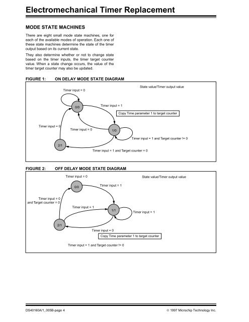
<strong>Electromechanical</strong> <strong>Timer</strong> <strong>Replacement</strong>MODE STATE MACHINESThere are eight small mode state machines, one foreach of the available modes of operation. Each one ofthese state machines determine the state of the timeroutput based on its current state.They also determine whether or not to change statebased on the timer inputs, the timer target countervalue. When a state change occurs, the value of thetimer target counter may also be updated.FIGURE 1:ON DELAY MODE STATE DIAGRAM<strong>Timer</strong> input = 0State value/<strong>Timer</strong> output value0/0<strong>Timer</strong> input = 1Copy Time parameter 1 to target counter<strong>Timer</strong> input = 02/1<strong>Timer</strong> input = 01/0<strong>Timer</strong> input = 1 and Target counter = 0<strong>Timer</strong> input = 1 and Target counter != 0FIGURE 2:OFF DELAY MODE STATE DIAGRAM<strong>Timer</strong> input = 0State value/<strong>Timer</strong> output value0/0<strong>Timer</strong> input = 1<strong>Timer</strong> input = 0and Target counter = 0<strong>Timer</strong> input = 11/1<strong>Timer</strong> input = 12/1<strong>Timer</strong> input = 0Copy Time parameter 1 to target counter<strong>Timer</strong> input = 1 and Target counter != 0DS40160A/1_005B-page 4© 1997 Microchip Technology Inc.