Landscape and Visual Assessment - Transpower
Landscape and Visual Assessment - Transpower
Landscape and Visual Assessment - Transpower

You also want an ePaper? Increase the reach of your titles
YUMPU automatically turns print PDFs into web optimized ePapers that Google loves.
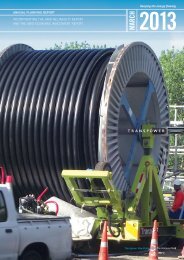
Paraparaumu 220kV SupplyConnection<strong>L<strong>and</strong>scape</strong> <strong>and</strong> <strong>Visual</strong> Effects <strong>Assessment</strong>Prepared for <strong>Transpower</strong> New Zeal<strong>and</strong> Limited9 May 2013
Document Quality AssuranceBibliographic reference for citation:Boffa Miskell Limited 2013. Paraparaumu 220kV Supply Connection: <strong>L<strong>and</strong>scape</strong> <strong>and</strong> <strong>Visual</strong>Effects <strong>Assessment</strong>. Report prepared by Boffa Miskell Limited for <strong>Transpower</strong> New Zeal<strong>and</strong>Limited.Prepared by:Rhys GirvanSenior <strong>L<strong>and</strong>scape</strong> PlannerBoffa Miskell LimitedReviewed by:Frank BoffaConsultant <strong>L<strong>and</strong>scape</strong> PlannerBoffa Miskell LimitedStatus: [FINAL] Revision / version: [0] Issue date: 9 May 2013Use <strong>and</strong> RelianceThis report has been prepared by Boffa Miskell Limited on the specific instructions of our Client. It is solely for our Client’suse for the purpose for which it is intended in accordance with the agreed scope of work. Boffa Miskell does notaccept any liability or responsibility in relation to the use of this report contrary to the above, or to any person otherthan the Client. Any use or reliance by a third party is at that party's own risk. Where information has been supplied bythe Client or obtained from other external sources, it has been assumed that it is accurate, without independentverification, unless otherwise indicated. No liability or responsibility is accepted by Boffa Miskell Limited for any errors oromissions to the extent that they arise from inaccurate information provided by the Client or any external source.Template revision: 20120608 0000File ref: W12086_24_<strong>L<strong>and</strong>scape</strong>_<strong>and</strong>_<strong>Visual</strong>_Assessmemt_20130508.docxCover photograph: View from Bright Property overlooking Paraparaumu Substation © Boffa Miskell, 2013
CONTENTS1.0 Introduction <strong>and</strong> Background 12.0 Paraparaumu 220kV Supply Options 22.1 Study Area 32.2 <strong>L<strong>and</strong>scape</strong> <strong>and</strong> <strong>Visual</strong> Considerations 42.3 Supply Option Conclusions <strong>and</strong> Selection of Option 1 43.0 The Proposed Development 53.1 Positive Effects from Line Removal 63.2 <strong>L<strong>and</strong>scape</strong> Design Principles used to inform Final Design 63.3 Consideration of Alternative Line Alignments 74.0 <strong>L<strong>and</strong>scape</strong> Context <strong>and</strong> Setting 74.1 <strong>L<strong>and</strong>scape</strong> Context of Akatarawa Ranges 74.2 Location <strong>and</strong> Setting of Proposed Development 84.3 <strong>L<strong>and</strong>scape</strong> Character Summary 95.0 <strong>L<strong>and</strong>scape</strong> <strong>and</strong> <strong>Visual</strong> <strong>Assessment</strong> 105.1 Approach <strong>and</strong> Methodology 105.2 Site Visits, Workshops <strong>and</strong> Input to Design 116.0 Statutory Planning Context 116.1 Resource Management Act 126.2 National Policy Statement on Electricity Transmission 126.3 Proposed Regional Policy Statement 126.4 Operative Kāpiti Coast District Plan 136.5 Proposed Kāpiti Coast District Plan (2012) 146.6 Key Statutory <strong>L<strong>and</strong>scape</strong> <strong>and</strong> <strong>Visual</strong> Considerations 157.0 Effects <strong>Assessment</strong> 167.1 Physical <strong>L<strong>and</strong>scape</strong> Effects 167.2 <strong>Visual</strong> Effects 197.3 Cumulative Effects 278.0 Mitigation <strong>and</strong> Monitoring 299.0 Temporary Effects 3010.0 Conclusion 3011.0 References 32U:\2012\W12086_HW_<strong>Transpower</strong>_PRM_220kV_Connection\Documents\E_<strong>L<strong>and</strong>scape</strong>\W12086_24_<strong>L<strong>and</strong>scape</strong>_<strong>and</strong>_<strong>Visual</strong>_Assessmemt_20130509.docx
AppendicesAppendix 1: <strong>L<strong>and</strong>scape</strong> <strong>and</strong> <strong>Visual</strong> Effects <strong>Assessment</strong> MethodologyAppendix 2: Kāpiti Coast District Council <strong>L<strong>and</strong>scape</strong> PolicyAppendix 3: <strong>Assessment</strong> of <strong>Visual</strong> EffectsAppendix 4: Implementation <strong>L<strong>and</strong>scape</strong> PrinciplesFiguresFigure 1: Proposed DevelopmentFigure 2: <strong>L<strong>and</strong>scape</strong> ContextFigure 3: District PlanFigure 4: Proposed District PlanFigure 5: Zone of Theoretical VisibilityFigure 6: <strong>Visual</strong> AppraisalFigure 7: <strong>Visual</strong> Simulation ViewpointsFigure 8: Valley Road Substation Vegetation RemovalFigure 9: Valley Road Substation <strong>L<strong>and</strong>scape</strong> StrategyFigure 10: Substation <strong>L<strong>and</strong>scape</strong> MitigationParaparaumu 220kV Supply Connection | <strong>L<strong>and</strong>scape</strong> <strong>and</strong> <strong>Visual</strong> Effects <strong>Assessment</strong>
1.0 Introduction <strong>and</strong> BackgroundIn recognition of the importance of the l<strong>and</strong>scape <strong>and</strong> amenity values in the Kāpiti Coast District,<strong>Transpower</strong> engaged Boffa Miskell to evaluate a new 220kV supply connection for Paraparaumu<strong>and</strong> to review <strong>and</strong> provide advice on potential l<strong>and</strong>scape <strong>and</strong> visual effects.As an initial step in this project, Boffa Miskell provided advice to <strong>Transpower</strong> on a number ofpotential electricity supply options adopting a modified ACRE 1 process. Based on this process,<strong>Transpower</strong> then selected their preferred supply option, which involved the construction of a newsubstation adjoining the existing Paraparaumu Substation <strong>and</strong> the construction of two singlecircuit 220kV transmission lines which connect with the Bunnythorpe - Hayward (BPE-HAY) A <strong>and</strong> Blines. The initial supply option assessment from which this option was selected is summarised inSection 2 of this report <strong>and</strong> detailed further in a separate report dated 31 January 2013.As the proposal will replace the need for an existing section of 110kV supply line betweenPauatahanui <strong>and</strong> Paraparaumu, consideration has also been given to the potential l<strong>and</strong>scape<strong>and</strong> visual benefits of removing part of the existing Mangahao to Paekakariki (MHO-PKK) A <strong>and</strong> B<strong>and</strong> Paekakariki to Takapu Road (PKK-TKR) A lines (approximately 24km of line in total). Anassessment considering the potential positive l<strong>and</strong>scape <strong>and</strong> visual effects of removing theseexisting lines has been set out in a separate report dated 24 th January 2013.Following <strong>Transpower</strong>’s selection of the preferred supply option, Boffa Miskell was furtherengaged by <strong>Transpower</strong> to assist with:• The siting of a new substation adjoining the existing Paraparaumu substation;• The selection of a preferred alignment for the transmission lines;• The assessment of the likely l<strong>and</strong>scape <strong>and</strong> visual effects associated with both theproposed substation <strong>and</strong> transmission lines; <strong>and</strong>• Consideration of potential l<strong>and</strong>scape <strong>and</strong> visual mitigation measures.The l<strong>and</strong>scape <strong>and</strong> visual effects assessment has been integral to the consideration <strong>and</strong>selection of the proposed supply option as well as the refinement <strong>and</strong> design of the preferredsupply option which was selected by <strong>Transpower</strong>. <strong>L<strong>and</strong>scape</strong> <strong>and</strong> visual considerations havebeen considered in a proactive, iterative <strong>and</strong> fully integrated manner with other environmental,technical <strong>and</strong> property considerations. Accordingly, the assessment of l<strong>and</strong>scape <strong>and</strong> visualeffects has not been carried out in isolation or simply in response to a particular proposal.In this regard, this l<strong>and</strong>scape <strong>and</strong> visual effects assessment follows a modified ACRE processadopted by <strong>Transpower</strong> which adopts an effects based process to arrive at <strong>and</strong> deliver the mostappropriate environmental outcome, with l<strong>and</strong>scape <strong>and</strong> visual effects considered throughoutthe area / corridor <strong>and</strong> siting / alignment selection process. Accordingly, this <strong>L<strong>and</strong>scape</strong> <strong>and</strong><strong>Visual</strong> Effects <strong>Assessment</strong> Report has been prepared as an environmentally integrated supplyselection process from the macro to the micro scale.1ACRE Process – An acronym for Area/Corridor/Route/Easement investigationsParaparaumu 220kV Supply Connection | <strong>L<strong>and</strong>scape</strong> <strong>and</strong> <strong>Visual</strong> Effects <strong>Assessment</strong>1
2.0 Paraparaumu 220kV Supply OptionsIn January 2013, Boffa Miskell reported on the l<strong>and</strong>scape <strong>and</strong> visual effects of the eight supplyoptions provided by <strong>Transpower</strong> 2 . This followed an Area of Study / Constraints workshop held toassess the technical / engineering, property <strong>and</strong> environmental constraints across the region <strong>and</strong>define the Study Area. <strong>Transpower</strong>’s Area of Study <strong>and</strong> <strong>Assessment</strong> Report is set out in Appendix Jof the AEE.The transmission options considered within the Study Area are described in Table 1 below:Table 1: Supply Options AssessedOption # Option DescriptionOption 1 A new 220/33 kV substation adjacent to the existing ParaparaumuSubstation <strong>and</strong> connected to the BPE–HAY A <strong>and</strong> B lines via:• a new 220 kV double circuit overhead line (towers or poles); <strong>and</strong>• a Double Tee.Option 1(a) A new 220/33 kV substation adjacent to the existing Paraparaumusubstation <strong>and</strong> connected to the BPE–HAY A <strong>and</strong> B lines via:• a new 220 kV double circuit overhead line (towers or poles); <strong>and</strong>• a new 220 kV switching station in an elevated position adjacent tothe BPE–HAY A <strong>and</strong> B lines.Option 2 A new 220/33 kV substation adjacent to the existing Paraparaumusubstation <strong>and</strong> connected to the BPE–WIL A line via:• a new 220 kV double circuit overhead line (towers or poles); <strong>and</strong>• a new 220 kV switching substation adjacent to the BPE–WIL A Line(possibly near Tower 231).Option 3 A new 220/33 kV substation on a site along Valley Road <strong>and</strong>connected to:• the BPE–HAY A <strong>and</strong> B lines via a new 220 kV double circuit line(towers or poles) with a Double Tee; <strong>and</strong>• the existing Paraparaumu substation via two new 33 kVunderground cable circuits.Option 3(a) A new 220/33 kV substation on a site along Valley Road <strong>and</strong>connected to:• the BPE–HAY A <strong>and</strong> B lines via two new double circuit 220 kVoverhead lines (towers or poles); <strong>and</strong>• the existing Paraparaumu substation via two new 33 kVunderground cable circuits.Option 4 A new 220/33 kV substation in an elevated position adjacent to theexisting BPE–HAY A <strong>and</strong> B lines <strong>and</strong> connected to:• the BPE–HAY A <strong>and</strong> B lines via a Double Tee (towers or poles); <strong>and</strong>• the existing Paraparaumu substation via two new 33 kVunderground cable circuits.Option 5 A new 220/33 kV substation in an elevated position adjacent to theexisting BPE–HAY A <strong>and</strong> B lines <strong>and</strong> connected to:• the BPE–HAY A <strong>and</strong> B lines via a Double Tee (towers or poles); <strong>and</strong>• the existing Paraparaumu substation via two new 33 kV overheadlines (on poles).Option 5(a) A new 220/33 kV substation station in an elevated position adjacent tothe existing BPE–HAY A <strong>and</strong> B lines <strong>and</strong> connected to:• the BPE–HAY A <strong>and</strong> B lines via a Switched Tee; <strong>and</strong>• the existing Paraparaumu substation via two new 33 kV overheadlines (on poles).2Paraparaumu 220kV Supply Connection: <strong>L<strong>and</strong>scape</strong> <strong>and</strong> <strong>Visual</strong> Considerations of Transmission Options – Boffa Miskell 2013Paraparaumu 220kV Supply Connection | <strong>L<strong>and</strong>scape</strong> <strong>and</strong> <strong>Visual</strong> Effects <strong>Assessment</strong>2
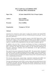
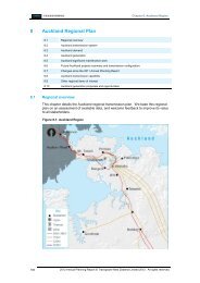
2.1 Study AreaThe area of l<strong>and</strong>scape encompassing the eight supply options occupies the easternedge of the larger Kāpiti Coast coastal plain, defining <strong>and</strong> forming the backdrop to thesettlement of Paraparaumu. The western boundary of the study area generallyculminates along the alignment of State Highway 1 <strong>and</strong> extends east into the foothills ofthe Tararua Ranges which create a series of ridgelines extending east towards theAkatarawa Ranges <strong>and</strong> encompasses Raumati Escarpment <strong>and</strong> Nikau Ridge. Theeastern edge of the study area culminates along the existing Bunnythorpe-Wilton (BPE-WIL) A line with the northern boundary of the study area culminating along theheadwaters of the Reikorangi Stream.All of the supply options traverse, in part, areas of Outst<strong>and</strong>ing <strong>L<strong>and</strong>scape</strong> identified inthe Operative Kāpiti Coast District Plan. This classification currently covers the l<strong>and</strong>forming the backdrop to Paraparaumu <strong>and</strong> includes the Tararua foothills which containthe existing BPE-HAY A <strong>and</strong> B lines. Within the Proposed Kāpiti Coast District Plan, thisarea of Outst<strong>and</strong>ing <strong>L<strong>and</strong>scape</strong> classification has been reclassified as a ‘SignificantAmenity <strong>L<strong>and</strong>scape</strong>’ <strong>and</strong> its extent redefined (made smaller), reducing the statutoryprotection in this area. The proposed changes to the classification of l<strong>and</strong>scape arediscussed further in Section 6 of this report.The extent of the Study Area, including l<strong>and</strong> currently classified as Outst<strong>and</strong>ing<strong>L<strong>and</strong>scape</strong> is illustrated below:Study AreaParaparaumu 220kV Supply Connection | <strong>L<strong>and</strong>scape</strong> <strong>and</strong> <strong>Visual</strong> Effects <strong>Assessment</strong>3
2.2 <strong>L<strong>and</strong>scape</strong> <strong>and</strong> <strong>Visual</strong> ConsiderationsGiven the recognised value of the l<strong>and</strong>scape in the area where supply options areidentified, a key l<strong>and</strong>scape <strong>and</strong> visual consideration formed the ability to minimise thescale <strong>and</strong> extent of l<strong>and</strong>scape <strong>and</strong> visual effects. To adequately address the potentialnature of l<strong>and</strong>scape <strong>and</strong> visual effects, nine l<strong>and</strong>scape principles were developedbased on the then current underst<strong>and</strong>ing of the project. These formed part of the basisfor considering <strong>and</strong> ranking the potential supply options <strong>and</strong> have been summarisedbelow:1 Minimise visual intrusion in Outst<strong>and</strong>ing <strong>L<strong>and</strong>scape</strong>Avoid Outst<strong>and</strong>ing Natural <strong>L<strong>and</strong>scape</strong>s wherever possible <strong>and</strong> minimise thescale <strong>and</strong> extent of any unavoidable development in this area2 Minimise visual intrusion in areas of high natural character, recreation value <strong>and</strong>amenityAvoid areas with High Natural Character in the Coastal Environment, ScenicReserves <strong>and</strong> other areas with potential high recreation amenity3 Minimise physical changes to the l<strong>and</strong>scapeWherever possible, minimise the extent of earthworks <strong>and</strong> removal of establishedvegetation4 Work within the framework of existing transmission structures wherever possibleAvoid extending into undeveloped areas wherever possible5 Reduce the extent to which new transmission elements are visibleSeek to contain new development within areas enclosed by existing topography<strong>and</strong> / or vegetation6 Minimise the extent of visibility from sensitive viewing audiencesWherever possible ensure that new development is not highly visible fromdwellings <strong>and</strong> recreation areas7 Minimise visual contrast with the existing environmentEnsure development appears consistent with the scale <strong>and</strong> form of existingdevelopment wherever possible8 Avoid new transmission elements along the skyline wherever possibleSeek to ensure that new development has the ability to recede into a natural orbuilt backdrop where visible from surrounding areas9 Minimise disruption to existing identified ecological areas <strong>and</strong> habitatsDisruption <strong>and</strong> fragmentation between identified ecological areas should beavoided wherever possible2.3 Supply Option Conclusions <strong>and</strong> Selection of Option 1Based on the l<strong>and</strong>scape assessment of the supply options (guided by the l<strong>and</strong>scapeprinciples noted above) <strong>and</strong> the terms of reference for the l<strong>and</strong>scape assessment, thefollowing conclusions were reached in relation to l<strong>and</strong>scape <strong>and</strong> visual effects of theeight broad supply options considered:• Option 3 has potential to generate the least potential comparative effects froma l<strong>and</strong>scape <strong>and</strong> visual perspective although elements of a new substationParaparaumu 220kV Supply Connection | <strong>L<strong>and</strong>scape</strong> <strong>and</strong> <strong>Visual</strong> Effects <strong>Assessment</strong>4
would likely remain visible from neighbouring rural residential dwellings alongValley Road which would require additional mitigation.• Options 1<strong>and</strong> 1A provide an opportunity to contain a new substation within anestablished area of vegetation associated with the existing Paraparaumusubstation. A new line connection with the existing BPE-HAY A <strong>and</strong> B lines wouldlikely increase visibility of line elements in this area compared with Option 3 <strong>and</strong>would require careful design to ensure potential visual effects are reduced.• A new elevated substation or switching station identified in Options 1A, 4, 5 <strong>and</strong>5A would introduce further potential visual effects from some properties withinNikau Valley which are avoided in Options 1 <strong>and</strong> 3. Such effects would likelyrequire additional mounding <strong>and</strong>/ or planting to ensure the impact of such viewsare effectively reduced with Option 4 also providing an opportunity to avoidviews of structures on the more visible face of areas of Outst<strong>and</strong>ing <strong>L<strong>and</strong>scape</strong>.• Option 2 provides the least preferred option from a l<strong>and</strong>scape <strong>and</strong> visualperspective extending visual effects through areas of Outst<strong>and</strong>ing <strong>L<strong>and</strong>scape</strong><strong>and</strong> into a broader area of rural l<strong>and</strong>scape which is not currently influenced bytransmission infrastructure <strong>and</strong> stretches east towards the Akatarawa Ranges.Following an overall transmission options assessment, which included consideration ofall technical/engineering, property <strong>and</strong> environmental matters for the above 8 options,Option 1 was selected as the overall preferred option. The Transmission Options<strong>Assessment</strong> Report can be found in Appendix K of the <strong>Assessment</strong> of EnvironmentalEffects report.3.0 The Proposed DevelopmentThe layout of the Proposed Development including the configuration of the proposed substation<strong>and</strong> transmission lines are shown on Figure 1: Proposed Development. A full description of theproposal is included in the NOR documents. In l<strong>and</strong>scape <strong>and</strong> visual terms the key features ofthe development are summarised below:• The substation is constructed on a level platform accessed along Valley Road with atotal area of approximately 2,400m 2 .• The maximum height of elements within the substation reach approximately 20 metresabove existing ground level (pole gantries) with all other built structures reachingapproximately 8 metres above existing ground level.• The proposed transmission lines will be constructed along 6 single circuit pole structures(P1 –P6) for each line reaches between approximately 16 <strong>and</strong> 31 meters above existingground level.• The proposed transmission line connections to the existing transmission lines will beformed using separate steel monopole tee structures reaching between 13 <strong>and</strong> 15metres above ground level adjacent to Tower 271 on the BPE-HAY A line <strong>and</strong> Tower 254on the BPE-HAY B line.• The proposed connection will be transmitted along 6 Simplex Goat conductors whicheach have a diameter of 25.97 mm with two 9.15mm earth wires strung along the top.Paraparaumu 220kV Supply Connection | <strong>L<strong>and</strong>scape</strong> <strong>and</strong> <strong>Visual</strong> Effects <strong>Assessment</strong>5
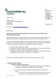
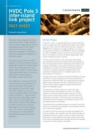
3.1 Positive Effects from Line RemovalThe removal of existing sections of 110kV line extending between Paraparaumu <strong>and</strong> Pauatahanuiwould result in the removal of 24 kilometres of transmission line <strong>and</strong> up to a total of 156 poles <strong>and</strong>towers. This removal will generate positive visual effects from areas where the existing lineappears prominent from adjoining roads <strong>and</strong> dwellings including Valley Road <strong>and</strong> rural lifestyleproperties accessed along Valley Road, Emerald Glen Road <strong>and</strong> within the Pauatahanui RollingHill Country. Over longer distances there will also be potential improvements in available viewswith removal of the visible detraction of utilitarian elements <strong>and</strong> reintegration of the existingtransmission corridor within the wider l<strong>and</strong>scape within which it is observed.View of existing MHO-PKK A <strong>and</strong> B linesconstructed along Valley RoadPotential view along Valley Road with MHO-PKK A <strong>and</strong>B lines removed3.2 <strong>L<strong>and</strong>scape</strong> Design Principles used to inform Final DesignAs identified in the options assessment (dated 31 January 2013), the proposed site forthe new substation adjoins the existing substation. This offers the ability to remain wellcontained with potential to avoid <strong>and</strong> mitigate l<strong>and</strong>scape <strong>and</strong> visual effects. To informthe final design for the new substation, a principle was to seek to retain <strong>and</strong> reinforceexisting screen vegetation as far as practicable.The alignment <strong>and</strong> form of the proposed transmission lines extending between theproposed substation <strong>and</strong> the existing elevated BPE-HAY A <strong>and</strong> B lines has undergone acareful design response to ensure potential visual effects can be effectively reduced.This approach has entailed an iterative design process which has taken account ofpotential l<strong>and</strong>scape <strong>and</strong> visual effects throughout the formulation of the final form <strong>and</strong>alignment. As part of this process the following design principles were identified <strong>and</strong>provided to <strong>Transpower</strong>:1. Reduce potential visual dominance of structures (poles preferred to towers)2. Minimise potential height of structures, particularly where they have potential toappear visible above the skyline (lower single circuit structures preferred to largerdouble circuit structures)3. Adopt the same general alignment of the existing 110kV line <strong>and</strong> remove existingconductors <strong>and</strong> poles replaced by the proposed 220kV lineParaparaumu 220kV Supply Connection | <strong>L<strong>and</strong>scape</strong> <strong>and</strong> <strong>Visual</strong> Effects <strong>Assessment</strong>6
4. Utilise l<strong>and</strong> form changes <strong>and</strong> existing vegetation as part of minimising potentialviews5. Where visible, make use of topography to increase the extent to which poles areseen against a l<strong>and</strong> backdrop <strong>and</strong> reduce the extent to which they are seenagainst the sky6. Minimise visibility of transmission development along the ‘dominant ridgeline’ asidentified in the Proposed Kāpiti Coast District Plan7. Maintain consistency in pole design along the length of the line to minimisecontrast between visible transmission elements8. Minimise sharp angles or ‘doglegs’ along the line alignment to reduce the overallnumber of poles <strong>and</strong> visibility of associated anchor structures9. Locate any necessary sharp angle changes in unobtrusive locations to reducevisual prominence10. Avoid locating poles or transmission lines through residential properties <strong>and</strong> limitthe overall number of properties which the line traverses11. Avoid removal of indigenous vegetation in listed ecological areas <strong>and</strong> minimiseremoval of other indigenous vegetation12. Locate pole platforms to minimise disruption to natural l<strong>and</strong>forms <strong>and</strong> reduce theneed for large cut batters3.3 Consideration of Alternative Line AlignmentsIn order to identify the alignment of the proposed transmission line, a number ofdifferent line options were considered as part of an iterative design process. Thisinvolved modelling the potential line options (including potenial double circuit, singlecircuit, tower <strong>and</strong> pole options) <strong>and</strong> identifying the preferred designs based on thedesign principles identified above. Following the selection of a preferred line design, theproposed alignment was then tested in the field through joint site visits with the designteam. This process involved the identification of any further potential engineering <strong>and</strong>construction constraints which were addressed in the final design in association withachieving the optimum ‘fit’ with the l<strong>and</strong>scape.4.0 <strong>L<strong>and</strong>scape</strong> Context <strong>and</strong> Setting4.1 <strong>L<strong>and</strong>scape</strong> Context of Akatarawa RangesThe wider l<strong>and</strong>scape context of the site was considered in the Kāpiti Coast District<strong>L<strong>and</strong>scape</strong> Study 3 incorporated within the Proposed Kāpiti Coast District Plan. Thel<strong>and</strong>scape character areas identified in this study have been illustrated on Figure 2:<strong>L<strong>and</strong>scape</strong> Context Plan. This plan identifies that the Proposed Development occupies3Isthmus (2011), Kāpiti Coast District <strong>L<strong>and</strong>scape</strong> StudyParaparaumu 220kV Supply Connection | <strong>L<strong>and</strong>scape</strong> <strong>and</strong> <strong>Visual</strong> Effects <strong>Assessment</strong>7
part of the Akatarawa Ranges l<strong>and</strong>scape character area <strong>and</strong> adjoins theParaparaumu Forel<strong>and</strong> <strong>and</strong> Paekakariki Dunefields l<strong>and</strong>scape character areas whichextend west across the Kāpiti Coast.The key l<strong>and</strong>scape characteristics of the Akatarawa Ranges l<strong>and</strong>scape character areaare set out below:• Gentler topography, immediacy to settlement <strong>and</strong> contribution to infrastructurenetworks;• Important l<strong>and</strong>marks; Wainui <strong>and</strong> Ohariu fault line, expressed as TransmissionGully <strong>and</strong> three distinct escarpments, well known lookout points <strong>and</strong> scenicdrives;• Escarpments from eastern barrier to transport <strong>and</strong> settlement, with basins behind;• Diverse vegetation patterns, substantial inl<strong>and</strong> indigenous remnants;• Recreational links for 4WD, mountain bike <strong>and</strong> walking tracks in the AkatarawaForest Park <strong>and</strong> along escarpments;• Historic use by Māori for cultivation areas, forest resources <strong>and</strong> transportationroutes; <strong>and</strong>• Associated with the District’s earliest productive l<strong>and</strong> use, US Marine Camp <strong>and</strong>now rural residential settlement on foothills <strong>and</strong> in valley systems.As illustrated on Figure 2, the Proposed Development is located along the westernedge of the Akatarawa Ranges. This area adjoins the existing eastern edge ofresidential development in Paraparaumu as this extends into a contained area ofresidential development at the northern end of Valley Road. The rural l<strong>and</strong>scapecontaining the proposed line forms part of the larger elevated backdrop toParaparaumu which includes the existing BPE-HAY A <strong>and</strong> B lines.4.2 Location <strong>and</strong> Setting of the Proposed DevelopmentThe location <strong>and</strong> setting of the proposed substation <strong>and</strong> transmission lines aredescribed separately below.4.2.1 Proposed SubstationThe proposed substation platform occupies approximately 2,400m 2 of l<strong>and</strong> directly tothe east of the existing Paraparaumu substation <strong>and</strong> accessed to the north-east alongValley Road. The existing Paraparaumu substation backs onto a number of residentialproperties along Ruapehu Street to the west <strong>and</strong> Valley Road to the south <strong>and</strong> east<strong>and</strong> separates the proposed substation from all but a single residential property locatedimmediately to the south at 70A Valley Road.Vegetation encompassed within the proposed substation site includes a mix of mowngrass <strong>and</strong> areas of indigenous <strong>and</strong> exotic shrub <strong>and</strong> tree species typically enclosing thesite along the road frontage. Species include satin wood (Phablaium squameum),karaka (Corynocarpus laevigatus), mahoe (Melicytus ramiflorus), kanuka (Kunzeaericoides) pittosporum (Pittosporum eugenioides) <strong>and</strong> some areas of more recentlyestablished griselinia, ake ake, hebe sp.. A semi mature pohutukawa (Metrosiderosexcelsa) is also located to the south-east of the site near an existing gated access way.Paraparaumu 220kV Supply Connection | <strong>L<strong>and</strong>scape</strong> <strong>and</strong> <strong>Visual</strong> Effects <strong>Assessment</strong>8
Existing overhead transmission lines influence the immediate l<strong>and</strong>scape context of theproposed substation site given its close proximity to the existing Paraparaumusubstation. Such development include the existing 110kV MHO-PKK gantries <strong>and</strong> towerswhich run through part of the proposed substation site <strong>and</strong> continue through theelevated rural l<strong>and</strong>scape to the north-east into Nikau Valley along a series of poles.Further domestic (low voltage) transmission lines are also established along Valley Roadin the immediate vicinity of the proposed substation.To the east of Valley Road, urban development continues into lower lying l<strong>and</strong> at thetoe of the rising slopes of the Tararura foothills. Such development includes the Te NikauTraining Centre (67 Valley Road) on the opposite side of Valley Road to the east of theproposed substation <strong>and</strong> a series of lifestyle properties following lower lying l<strong>and</strong> furtherto the east. Beyond this development, the l<strong>and</strong> rises to form a more open <strong>and</strong> visiblerural backdrop along the foothills of the Tararua Ranges <strong>and</strong> accommodating themore elevated BPE-HAY A <strong>and</strong> B lines.There are no existing watercourses in the area where the substation is proposed. To thenorth of the proposed substation, a tributary of the Wharemauku Stream runs parallelwith Valley Road <strong>and</strong> flows from the foothills of the Tararua Ranges to the west. Thisstream broadly divides the rising form of the Nikau escarpment to the north <strong>and</strong> theAkatarawa foothills which rise to the east of Valley Road.4.2.2 Proposed Transmission LineThe proposed transmission line extends to the north-east of the proposed substation <strong>and</strong>connects with the existing BPE-HAY A <strong>and</strong> B lines. This covers a total distance ofapproximately 800 metres.The alignment of the proposed transmission lines resembles the alignment of the existingMHO-PKK A <strong>and</strong> B lines which are to be removed. These extend to the north-east of theexisting Paraparaumu substation towards an elevated valley which continues norththrough Nikau Valley. The southern end of the proposed line spans an area of remnantswamp forest running west-east through the base of the gully. This area includes thetributary of the Wharemauku Stream. To the north of the gully, the proposed lineextends through an elevated area of working rural l<strong>and</strong>scape containing apredominant cover of grass <strong>and</strong> clumps of kanuka <strong>and</strong> other regenerating indigenousvegetation in the gullies.The northern section of the proposed lines connects with the BPE-HAY A <strong>and</strong> B linesapproximately 600 metres south of Nikau Palm Road. To form this connection, teejunctions are proposed adjacent to Tower 271( BPE-HAY A) <strong>and</strong> Tower 254 (BPE-HAY B).The larger l<strong>and</strong>form containing the proposed transmission line forms the toe of theAkatarawa Ranges <strong>and</strong> part of the backdrop to Paraparaumu.4.3 <strong>L<strong>and</strong>scape</strong> Character SummaryIn summary, the existing character <strong>and</strong> setting associated with the ProposedDevelopment can be summarised as follows:• The wider l<strong>and</strong>scape forms the foothills of the Akatarawa Ranges characterisedby the immediacy to the settlement of Paraparaumu <strong>and</strong> including existinginfrastructure networks;• The proposed substation adjoins the existing Paraparaumu substation within anestablished urban area;Paraparaumu 220kV Supply Connection | <strong>L<strong>and</strong>scape</strong> <strong>and</strong> <strong>Visual</strong> Effects <strong>Assessment</strong>9
• Vegetation encompassed within the proposed substation site includes a mix ofexotic <strong>and</strong> indigenous plant species <strong>and</strong> generally encloses the substation sitealong Valley Road;• The proposed transmission lines extend from the urban area into a rural area<strong>and</strong> generally follows the same general alignment of the existing MHO-PKK A<strong>and</strong> B lines which are to be removed in this location;• The southern end of the proposed transmission lines span remnant indigenousvegetation established along the alignment of a tributary of the WharemaukuStream; <strong>and</strong>• The northern area of the proposed transmission lines extends towards theexisting BPE-HAY A <strong>and</strong> B line within an elevated <strong>and</strong> open working rurall<strong>and</strong>scape.5.0 <strong>L<strong>and</strong>scape</strong> <strong>and</strong> <strong>Visual</strong> <strong>Assessment</strong><strong>L<strong>and</strong>scape</strong> <strong>and</strong> visual assessments are separate, although linked, procedures. The existingl<strong>and</strong>scape <strong>and</strong> its existing visual context all contribute to the existing ‘baseline’ for l<strong>and</strong>scape<strong>and</strong> visual assessments. <strong>Visual</strong> effects are assessed as one of the interrelated effects on people.The assessment of the potential effect on l<strong>and</strong>scape is carried out as an effect on anenvironmental resource, ie. l<strong>and</strong>scape features <strong>and</strong> l<strong>and</strong>scape character.In summary, the assessment of effects aims to:• Identify systematically the potential l<strong>and</strong>scape <strong>and</strong> visual effects of thedevelopment;• Develop measures to avoid, remedy or mitigate adverse effects, primarily as part ofthe iterative design process <strong>and</strong> then as more specific mitigation measures; <strong>and</strong>• Provide an assessment <strong>and</strong> professional judgement as to the significance ofl<strong>and</strong>scape <strong>and</strong> visual effects which will result from the Proposed Development.Effects may be positive (beneficial), neutral (no discernible change), or negative (adverse),direct or indirect, <strong>and</strong> can be temporary (short, medium, or long term), permanent or cumulative.They can also arise at different scales (local, regional, or national) <strong>and</strong> have different levels ofsignificance.5.1 Approach <strong>and</strong> MethodologyThe l<strong>and</strong>scape <strong>and</strong> visual assessment was undertaken concurrently during the design ofthe project. This approach has influenced the final location <strong>and</strong> form of the proposedsubstation <strong>and</strong> lines <strong>and</strong> has included the development of associated l<strong>and</strong>scapeprinciples to avoid, remedy or mitigate potential l<strong>and</strong>scape <strong>and</strong> visual effects.This assessment considers the potential l<strong>and</strong>scape <strong>and</strong> visual effects of the proposal inthe context of the wider l<strong>and</strong>scape, together with those that are likely to beexperienced from locations close to the site. In particular, the visual assessment focusesParaparaumu 220kV Supply Connection | <strong>L<strong>and</strong>scape</strong> <strong>and</strong> <strong>Visual</strong> Effects <strong>Assessment</strong>10
on views from public locations as part of identifying the likely significance of effectsfrom the wider available viewing audience.The methodology used for the assessment involved a combination of fieldwork, visibilityanalysis <strong>and</strong> photographic simulations from various public viewpoints, with the findingsof this assessment set out in section 7.0 below. Views from individual dwellings were notobtained for the purpose for this assessment with representative viewpoints obtained toassess the likely nature of views from the nearest available publically accessibleviewpoint. A full methodology discussing the l<strong>and</strong>scape <strong>and</strong> visual effects assessmentprocess is set out in Appendix 1.5.2 Site Visits, Workshops <strong>and</strong> Input to DesignIn accordance with the iterative design process which was undertaken <strong>and</strong> themethodology outlined in Appendix 1, site visits <strong>and</strong> workshops to inform the ProposedDevelopment <strong>and</strong> assess the nature of potential l<strong>and</strong>scape <strong>and</strong> visual effects includedthe following:i) Area of Study/Constraints workshop on the 4 th October 2012ii)An initial project team site visit to review the locations of the possibletransmission options on the 25 th October 2012iii) Options <strong>Assessment</strong> Workshop on the 6 th November 2012iv)Site visit to observe the existing MHO-PKK A <strong>and</strong> B lines <strong>and</strong> PKK – TKR A lineswith potential to be removed on the 9 th November 2012v) Site visit with the project team to walk the indicative alignment of the proposedtransmission lines <strong>and</strong> the location of the proposed substation on the 15 thFebruary 2013vi)vii)viii)Site visit to identify the location of representative viewpoints used within thel<strong>and</strong>scape <strong>and</strong> visual assessment on the 26 th February 2013Site visit with the transmission line design team to identity alternative locationsof a potential transmission line following the identification of potentialdevelopment constraints on the 1 st March 2013.Site visit with the transmission line design <strong>and</strong> construction team <strong>and</strong> to discussfinal pole locations <strong>and</strong> potential construction techniques on the 20 th March20136.0 Statutory Planning ContextThe statutory planning context outlined below sets out the relevant matters to be considered inthe <strong>L<strong>and</strong>scape</strong> <strong>and</strong> <strong>Visual</strong> Effects <strong>Assessment</strong> in Section 7 of this report.Paraparaumu 220kV Supply Connection | <strong>L<strong>and</strong>scape</strong> <strong>and</strong> <strong>Visual</strong> Effects <strong>Assessment</strong>11
6.1 Resource Management ActThe relevant RMA provisions addressed in this report will be in respect of the following:Section 6(b) - the protection of outst<strong>and</strong>ing natural features <strong>and</strong> l<strong>and</strong>scapesfrom inappropriate subdivision, use <strong>and</strong> developmentSection 7(c) - the maintenance <strong>and</strong> enhancement of amenity valuesSection 7(f) – the maintenance <strong>and</strong> enhancement of the quality of theenvironment6.2 National Policy Statement on Electricity TransmissionThe National Policy Statement on Electricity Transmission (NPSET) sets out the nationalpolicy framework for managing the effects of the electricity transmission network underthe RMA. Policies with relevance to this l<strong>and</strong>scape <strong>and</strong> visual assessment include thefollowing:Policy 4 - When considering the environmental effects of new transmissioninfrastructure or major upgrades of existing transmission infrastructure,decision-makers must have regard to the extent to which any adverseeffects have been avoided, remedied or mitigated by the route, site <strong>and</strong>method selection.Policy 6 - Substantial upgrades of transmission infrastructure should beused as an opportunity to reduce existing adverse effects of transmissionincluding such effects on sensitive activities where appropriate.Policy 7 - Planning <strong>and</strong> development of the transmission system shouldminimise adverse effects on urban amenity <strong>and</strong> avoid adverse effects ontown centres <strong>and</strong> areas of high recreational value or amenity <strong>and</strong> existingsensitive activities.Policy 8 - In rural environments, planning <strong>and</strong> development of thetransmission system should seek to avoid adverse effects on outst<strong>and</strong>ingnatural l<strong>and</strong>scapes, areas of high natural character <strong>and</strong> areas of highrecreation value <strong>and</strong> amenity <strong>and</strong> existing sensitive activities.6.3 Proposed Regional Policy StatementThe Proposed Regional Policy Statement follows a comprehensive review of theOperative Regional Policy Statement. The Proposed Regional Policy Statement requiresthat district <strong>and</strong> regional plans identity outst<strong>and</strong>ing natural features <strong>and</strong> l<strong>and</strong>scapes(Policy 24) <strong>and</strong> protect these from inappropriate subdivision, use or development(Policy 25). Policies also refer to identifying Significant Amenity <strong>L<strong>and</strong>scape</strong>s (Policy 26)<strong>and</strong> district <strong>and</strong> regional plans including policies, rules <strong>and</strong> methods for managingthese l<strong>and</strong>scapes to maintain or enhance their significant amenity values (Policy 27).Policy 49 provides further guidance with respect to managing effects on outst<strong>and</strong>ingnatural features <strong>and</strong> l<strong>and</strong>scape <strong>and</strong> significant amenity l<strong>and</strong>scapes <strong>and</strong> states:When considering an application for a resource consent, notice ofrequirement or a change, variation or replacement to review of a districtor regional plan, a determination shall be made as to firstly, whether anactivity may affect an outst<strong>and</strong>ing natural feature <strong>and</strong>/or l<strong>and</strong>scape, orsignificant amenity l<strong>and</strong>scape, <strong>and</strong>/or secondly, determining whether orParaparaumu 220kV Supply Connection | <strong>L<strong>and</strong>scape</strong> <strong>and</strong> <strong>Visual</strong> Effects <strong>Assessment</strong>12
not an activity is inappropriate, having particular regard shall be given tothe following:(a)the degree to which the natural feature or l<strong>and</strong>scape values willbe modified, damaged or destroyed including:(i) the duration <strong>and</strong> frequency of any effect, <strong>and</strong>/or(ii) the magnitude or scale of any effect;(b)(c)(d)(e)the irreversibility of adverse effects on l<strong>and</strong>scape values;the resilience of the natural feature place or area to change;the opportunities to remedy or mitigate previous damage tonatural feature or l<strong>and</strong>scape values; <strong>and</strong>whether the activity will lead to cumulative adverse effects onthe natural feature or l<strong>and</strong>scape values.6.4 Operative Kāpiti Coast District PlanThe proposed development is contained entirely within the jurisdiction of the KāpitiCoast District Council (KCDC), with relevant policies from KCDC’s Operative District Planillustrated on Figure 2. Within the Operative District Plan, the proposed substation ispartially located within Designation #D0801 which accommodates the existingParaparaumu substation <strong>and</strong> entirely located with an underlying Residential Zone,forming part of the existing urban area associated with Paraparaumu. The urban area isnot the subject of any underlying l<strong>and</strong>scape classifications.The proposed transmission lines connect between the proposed substation <strong>and</strong> theexisting BPE-HAY A <strong>and</strong> B lines <strong>and</strong> passes through Residential, Open Space <strong>and</strong> RuralZones. Part of the proposed transmission lines also span Kaitawa Reserve (EcologicalArea #K150) covering part of the remnant swamp forest established along a tributary ofthe Wharemeuku Stream. Heritage Building #B29 located within Te Nikau Bible Collegeis also located approximately 100 metres from the proposed substation <strong>and</strong> southernend of the transmission lines.As discussed previously <strong>and</strong> illustrated on Figure 3, part of the proposed transmission linealso extends into Outst<strong>and</strong>ing <strong>L<strong>and</strong>scape</strong> as identified in the Operative District Plan.The Operative District Plan identifies that it is important to protect these l<strong>and</strong>scapes toretain the open rural <strong>and</strong> natural "unspoilt" character of the Kāpiti Coast District. Theclassification of Outst<strong>and</strong>ing <strong>L<strong>and</strong>scape</strong> has been reviewed as part of the ProposedKāpiti Coast District Plan <strong>and</strong> redefined as a Significant Amenity <strong>L<strong>and</strong>scape</strong> inrecognition of a lower level of l<strong>and</strong>scape value identified in this area.Objectives <strong>and</strong> policies with relevance to this l<strong>and</strong>scape <strong>and</strong> visual assessment areincluded in Section C1: Residential Zone; Section C2: Rural Zone, Section C10:<strong>L<strong>and</strong>scape</strong>; Section C12: Open Spaces <strong>and</strong> Reserves; <strong>and</strong> Section C16: Network Utilitiesof the District Plan with the full wording of relevant l<strong>and</strong>scape policies set out inAppendix 2 to this report. Relevant policies as they apply to potential l<strong>and</strong>scape <strong>and</strong>visual effects are summarised below:Residential ZoneThe residential zone requires activities to maintain a residential appearance <strong>and</strong>low density <strong>and</strong> quiet character. In preventing a decline in the amenity values ofParaparaumu 220kV Supply Connection | <strong>L<strong>and</strong>scape</strong> <strong>and</strong> <strong>Visual</strong> Effects <strong>Assessment</strong>13
this environment, potential effects are set out in Policy 1 <strong>and</strong> include for theconsideration of the clearance of vegetation, changes to the l<strong>and</strong>form,imposition of visually obtrusive structures <strong>and</strong> the degradation of the naturalenvironment.Rural ZoneThe rural zone includes measures to identify <strong>and</strong> protect significant indigenousvegetation (Policy 1(A)) <strong>and</strong> ensuring effects on the natural environment areavoided, remedied or mitigated (Policy 1(B)). Policy 2 also has particularrelevance to Outst<strong>and</strong>ing <strong>L<strong>and</strong>scape</strong>s in the rural zone <strong>and</strong> seeks to maintain,enhance <strong>and</strong> protect the district’s outst<strong>and</strong>ing l<strong>and</strong>scapes in the Rural Zone frominappropriate subdivision, use <strong>and</strong> development.Outst<strong>and</strong>ing <strong>L<strong>and</strong>scape</strong>Policy specific to Outst<strong>and</strong>ing <strong>L<strong>and</strong>scape</strong> seeks to ensure that new structures<strong>and</strong> earthworks are located so that they will not be visually dominant <strong>and</strong>requires siting development below the dominant ridge line where practicable(Policy 1). Policy 3 relates to ensuring that no l<strong>and</strong>form modification occurs withinoutst<strong>and</strong>ing l<strong>and</strong>scapes of the open space <strong>and</strong> rural zones, except for theminimum necessary associated with access <strong>and</strong> the provision of services. Policy 4also lists the names of Outst<strong>and</strong>ing <strong>L<strong>and</strong>scape</strong>s illustrated within planning mapswith the Proposed Development identified within ‘the foothills of the TararuaRanges including Pukehou hill’.Open Space ZoneThe open space zone relates to the open space <strong>and</strong> recreation resources of thedistrict. In recognising the application of relevant l<strong>and</strong>scape policy in this zone, itis of note that there are no existing recreation uses in the area where thetransmission line is proposed. The relevance of this zone therefore relates torecognising the open space amenity on private l<strong>and</strong> including native trees,significant l<strong>and</strong>forms <strong>and</strong> natural character.Network UtilitiesThese policies provide for the development of network utilities whist ensuring thatadverse effects on the environment are avoided, remedied or mitigated.Potential l<strong>and</strong>scape effects to be addressed include significant adverse effectson l<strong>and</strong>scape <strong>and</strong> amenity values including visual effects <strong>and</strong> significantadverse effects on the natural environment.6.5 Proposed Kāpiti Coast District Plan (2012)The Proposed Kāpiti Coast District Plan was notified in December 2012 <strong>and</strong> includesobjectives <strong>and</strong> policies relevant to considering potential l<strong>and</strong>scape <strong>and</strong> visual effectsin Section 3: Natural Environment, Section 5: Living Environment, Section 7: RuralEnvironment <strong>and</strong> Section 11: Network Utilities. Policies with relevance to this l<strong>and</strong>scape<strong>and</strong> visual assessment have also been reproduced in Appendix 2 at the end of thisreport.Within the Proposed District Plan, the l<strong>and</strong> currently classified as Outst<strong>and</strong>ing<strong>L<strong>and</strong>scape</strong> in the area where the transmission lines are proposed has been reclassifiedas a Significant Amenity <strong>L<strong>and</strong>scape</strong>. The extent of the proposed Significant Amenity<strong>L<strong>and</strong>scape</strong> classification is illustrated on Figure 4.The proposed Significant Amenity <strong>L<strong>and</strong>scape</strong> classification covers part of the widerfoothills <strong>and</strong> outlier of the Akatarawa range that extend from Ruapehu Street to theMuaupoko Stream <strong>and</strong> has been broadly identified as the ‘Nikau Escarpment <strong>and</strong>Paraparaumu 220kV Supply Connection | <strong>L<strong>and</strong>scape</strong> <strong>and</strong> <strong>Visual</strong> Effects <strong>Assessment</strong>14
Otaihanga Foothills’. In this area, proposed policy 3.19 directs that developmentminimise changes to the predominant vegetation pattern, cluster development withexisting structures, retain areas of indigenous vegetation, <strong>and</strong> minimise earthworks toretain natural l<strong>and</strong>forms.In identifying the values of Significant Amenity <strong>L<strong>and</strong>scape</strong>, the Proposed District Planalso identities potential l<strong>and</strong>scape threats specific to the Proposed Otaihanga Foothills<strong>and</strong> Nikau Escarpment within which development is proposed. Such threats include:’Indigenous vegetation removal, infrastructure development/upgrades, [residential]development typology, location, height, density including effects on ridgeline/skyline<strong>and</strong> rural character along the majority extent of the escarpment.’As part of the review of l<strong>and</strong>scape provisions, the Proposed District Plan has alsoidentified ‘Dominant Ridgelines’ in elevated areas, one of which occurs in theimmediate vicinity of the proposed transmission line (see Figure 4). Proposed Policy 3.21directs development to avoid these areas to ensure that views to <strong>and</strong> from visuallyprominent l<strong>and</strong>forms remain intact. In defining these features, the Proposed District Planidentifies that Dominant Ridgelines have been mapped as indicative features. Theassessment process or specific values represented by each Dominant ridgeline areahave not been defined within the Proposed Plan.In addition to changes to l<strong>and</strong>scape provisions as described above, the ProposedDistrict Plan also replaces the existing Open Space Zone in the area where theproposed transmission lines are proposed with a Rural Hills Zone forming part of thelarger Rural Environment (see Figure 4). The Rural Hills Zone recognises the individualcharacteristics <strong>and</strong> anticipated uses of the foothills of the Tararua ranges as one of fivezones which form the larger rural environment within the Kāpiti Coast District. Within theRural Hills Zone it is intended that all development be undertaken in a manner which issympathetic to the high l<strong>and</strong>scape character <strong>and</strong> visibility of the area includingretention of the natural state of l<strong>and</strong>forms.The Proposed District Plan also includes a new area described as ‘Priority areas forRestoration’ as illustrated on Figure 4. This area follows the alignment of the tributary tothe Wharemauku Stream through the urban area <strong>and</strong> into the adjoining rurall<strong>and</strong>scape <strong>and</strong> encompasses part of the Proposed Development area including theproposed substation. Policy 3.14 relating to this area refers to active restoration orremediation in order to achieve biodiversity benefits including resilient riparian buffers<strong>and</strong> planting of indigenous vegetation linking remnant habits.As illustrated on Figure 4, the Proposed Development falls outside of the identifiedCoastal Environment as defined in the Proposed District Plan.6.6 Key Statutory <strong>L<strong>and</strong>scape</strong> <strong>and</strong> <strong>Visual</strong> ConsiderationsBased on the statutory planning provisions, the key l<strong>and</strong>scape <strong>and</strong> visual considerationswhich have been identified are outlined below:• Part of the proposed transmission lines extend through an area currentlyclassified as an Outst<strong>and</strong>ing <strong>L<strong>and</strong>scape</strong>, which requires that new developmentis not visually dominant (e.g. below the dominant ridge line where practicable)<strong>and</strong> that a minimum level of earthworks is undertaken;• In recognition of the lower l<strong>and</strong>scape values identified within the Study Area,the area of Outst<strong>and</strong>ing <strong>L<strong>and</strong>scape</strong> is proposed to be reclassified as aSignificant Amenity <strong>L<strong>and</strong>scape</strong> in the Proposed Kāpiti District Plan.Paraparaumu 220kV Supply Connection | <strong>L<strong>and</strong>scape</strong> <strong>and</strong> <strong>Visual</strong> Effects <strong>Assessment</strong>15
• Within the proposed Significant Amenity <strong>L<strong>and</strong>scape</strong>, development should seekto avoid ‘Dominant Ridgelines’ <strong>and</strong> minimise changes to vegetation patterns<strong>and</strong> natural l<strong>and</strong>forms;• Within the residential environment, the proposed substation should not reducethe character <strong>and</strong> residential amenity of the urban area having particularregard to clearance of vegetation, changes to the l<strong>and</strong>form <strong>and</strong> theimposition of visually obtrusive structures;• Within the rural environment, the proposed transmission lines should remainsympathetic to the natural environment, including minimising effects on openspace amenity, indigenous vegetation <strong>and</strong> natural l<strong>and</strong>forms; <strong>and</strong>• Policy provides for the operation, use <strong>and</strong> development of utilities networkswhilst seeking to avoid, remedy or mitigate significant adverse effects onl<strong>and</strong>scape <strong>and</strong> amenity values including visual effects.7.0 Effects <strong>Assessment</strong>The direct physical effects of the Proposed Development, relate to earthworks associated withaccommodating the proposed substation platform, poles, tee junctions <strong>and</strong> access tracks withinthe existing l<strong>and</strong>form. Direct physical effects also include vegetation removal in order toaccommodate the proposed substation with more limited vegetation clearance occurring inrelation to introducing transmission lines within the working rural l<strong>and</strong>scape which has apredominant cover of pasture.Whilst the scale of the proposed transmission lines will increase as a result of differences infunctional requirements between the existing 110kV supply connection <strong>and</strong> the proposed 220kVconnection, the resultant development will occur in a similar location <strong>and</strong> setting to that whichcurrently exists. Once completed, the proposed poles <strong>and</strong> conductors will be seen from a similarviewing audience which observes the existing MHO-PKK A <strong>and</strong> B <strong>and</strong> BLE-HAY A <strong>and</strong> B lines <strong>and</strong>will not appear unusual or uncharacteristic in this context. Reducing modification to this area ofl<strong>and</strong>scape, including minimising potential effects along dominate ridgelines, has also formed akey driver in seeking to avoid, remedy or mitigate potential adverse effects.7.1 Physical <strong>L<strong>and</strong>scape</strong> EffectsFor the purpose of this assessment, the nature of potential l<strong>and</strong>scape effects associatedwith the proposed substation <strong>and</strong> transmission lines have been set out separatelybelow.7.1.1 Proposed SubstationFull details of the proposed substation are set out in the AEE with the key elementssummarised as follows:• The proposed substation is contained within an area of valley floor located at72.4 metres above sea level (masl).Paraparaumu 220kV Supply Connection | <strong>L<strong>and</strong>scape</strong> <strong>and</strong> <strong>Visual</strong> Effects <strong>Assessment</strong>16
• Two steel pi-pole gantries to receive the 220 kV overhead circuits, each nomore than 20 m high <strong>and</strong> 14 m wide.• Two bays of 220 kV switching, measuring <strong>and</strong> protection equipment betweenthe transformers <strong>and</strong> pi-pole structures.• Two 220/33 kV transformers, including acoustic walls reaching approximately 7metres in height along the south <strong>and</strong> south-east sides of the transformers• Two firewalls enclosing the substation <strong>and</strong> reaching approximately 8m in height<strong>and</strong> 15m in length.• Retaining walls reaching up to 2m <strong>and</strong> 3.5 in height along the respectiveeastern <strong>and</strong> northern boundaries• 2m security fencing enclosing the substation platform.• Access ways <strong>and</strong> manoeuvring areas.L<strong>and</strong>formThe proposed substation occupies an area of previously developed l<strong>and</strong> adjoining anexisting substation <strong>and</strong> contained along a wider area of valley floor. Areas of earliermodification to the existing l<strong>and</strong>form can be identified across the site, including worksassociated with accommodating the existing switching yard. Accordingly, the modifiedl<strong>and</strong>form associated with the proposed substation site is assessed as having a low levelof sensitivity <strong>and</strong> tolerant of change.Earthworks associated with accommodating the proposed substation entail benchinga platform of approximately 2,400 m 2 within an existing modified <strong>and</strong> gently slopingarea of l<strong>and</strong>. A total volume of approximately 1,200 m 3 of earthworks is proposed in thisarea <strong>and</strong> entails cutting the substation platform down into the site by approximately 2metres in the south-east corner <strong>and</strong> filling by a maximum height of 3.5 metres in thenorth-west corner. The proposed bench is to be stepped by approximately 2.9 metresabove the existing Paraparaumu substation. This forms a levelled platform loweredfrom the most sensitive adjoining vantage points to the east along Valley Road.Overall, earthworks associated with the substation will represent a low-moderatemagnitude of change with a low significance of effect.VegetationIn order to accommodate the proposed substation, approximately 2,000m 2 of existingestablished <strong>and</strong> recently planted vegetation will be removed as illustrated on Figure 8.Such vegetation includes a mix of indigenous shrubs <strong>and</strong> exotic shelter planting. Givenits limited l<strong>and</strong>scape value <strong>and</strong> visual containment from most external areas, suchvegetation is assessed as having a low level of sensitivity <strong>and</strong> tolerant of change.In order to limit the potential impacts of vegetation loss <strong>and</strong> better contain visualeffects from surrounding dwellings, areas of existing vegetation surrounding the existingsubstation will be retained. This retention could include an 8 metre pohutakawa tree inthe south-east corner <strong>and</strong> part of an established phebalium hedge also reachingapproximately 8 metres in height in the north-east corner.As detailed in Section 8.0: Mitigation <strong>and</strong> Monitoring, the proposed substation site alsoaccommodates a corridor of l<strong>and</strong> around the northern <strong>and</strong> eastern boundaries in orderto mitigate for vegetation loss. Planting in this area will accommodate additionalplanting which reflects indigenous vegetation found in the surrounding area <strong>and</strong>reinforce the existing vegetative screen. In this context, the physical effects ofvegetation loss associated with accommodating the proposed substation will representParaparaumu 220kV Supply Connection | <strong>L<strong>and</strong>scape</strong> <strong>and</strong> <strong>Visual</strong> Effects <strong>Assessment</strong>17
a moderate magnitude of change on an area of low sensitivity vegetation. Overall thiswill result in a low significance of effect.7.1.2 Proposed Transmission LinesThe proposed transmission line covers approximately 800 metres <strong>and</strong> connects the newsubstation with the BPE-HAY A <strong>and</strong> B lines. The proposed transmission line includes sixnew pi-pole structures (P1 – P6) which reach between 16 <strong>and</strong> 30 metres above existingground level <strong>and</strong> six new single pole tee structures which reach approximately 15 metreadjacent to Tower 271( BPE-HAY A) <strong>and</strong> Tower 254 (BPE-HAY B). Figure 1: ProposedDevelopment shows the indicative alignment, pole locations <strong>and</strong> pole heights 4 .L<strong>and</strong>formThe proposed transmission lines extend to the north-east of the proposed substation <strong>and</strong>into an elevated rural l<strong>and</strong>scape with moderate <strong>and</strong> steep slopes visible fromsurrounding areas. The open character of this l<strong>and</strong>scape <strong>and</strong> its associated l<strong>and</strong>formsare recognised as having high l<strong>and</strong>scape value, albeit downgraded from anOutst<strong>and</strong>ing <strong>L<strong>and</strong>scape</strong> to a Significant Amenity <strong>L<strong>and</strong>scape</strong> in the Proposed DistrictPlan. Accordingly, the sensitivity of the l<strong>and</strong>scape in which the transmission lines areproposed has been assessed as moderate to high.Within the rural l<strong>and</strong>scape, the proposed pole locations have been sited in order to limitdisturbance to existing l<strong>and</strong>form features <strong>and</strong> further minimise potential l<strong>and</strong>scape <strong>and</strong>visual effects. As part of this process, pole locations have been predominately locatedon areas with slightly flatter topography, to reduce the extent of earthworks <strong>and</strong>minimise potential disruption to wider area of l<strong>and</strong>scape.In order to construct the proposed pole <strong>and</strong> tee structures, a total volume ofapproximately 1,000m 3 of earthworks is proposed to form temporary platforms withinwhich foundations are formed <strong>and</strong> structures are erected. These will entail temporarybenching to form a level construction platform of approximately 3 x 6 metres per pole<strong>and</strong> will necessitate cut heights of up to approximately 4 metres. These localisedimpacts will be reinstated at the completion of development in order to remedy visualeffects.Wherever possible, access will be provided by upgrading existing access tracks. Thispredominately entails scraping the existing surface <strong>and</strong> laying new areas of gravel.Batter slopes exposed by upgrading works are proposed to be re-contoured into theexisting slope <strong>and</strong> re-established with pasture or other suitable vegetation to integratewith the surrounding rural l<strong>and</strong> use.In areas where upgrading pre-existing tracks would otherwise require more significant<strong>and</strong> visible cut <strong>and</strong> batter slopes, temporary access methods will be used in order tominimise potential physical l<strong>and</strong>scape effects. This approach includes the use ofequipment with self laying tracks along the existing spurs to provide access to proposedpoles P1 to P4. Aerial delivery of other necessary equipment <strong>and</strong> materials will also beused. During construction, this access arrangement will reduce the scale of disruptionto the existing l<strong>and</strong>form.Once established, earthworks associated with pole platforms <strong>and</strong> temporary access willbe rehabilitated to resemble the existing l<strong>and</strong>form <strong>and</strong> reinstated with pasture or othersimilar vegetation which integrates within the surrounding rural l<strong>and</strong> use. This will4The effects assessment takes account of slight adjustments to the height <strong>and</strong> locations of pole elements resulting fromdetailed design as outlined in the AEE. This includes a potential increase in height of up to 5 meters <strong>and</strong> relocating poles byup to 20 m.Paraparaumu 220kV Supply Connection | <strong>L<strong>and</strong>scape</strong> <strong>and</strong> <strong>Visual</strong> Effects <strong>Assessment</strong>18
epresent a low-moderate magnitude of change on an area of moderate to highsensitivity l<strong>and</strong>scape <strong>and</strong> represents a moderate significance of effect overall.VegetationThe proposed transmission lines have been sited to minimise the loss of existingvegetation <strong>and</strong> avoids the requirement to remove vegetation within Ecological Area#K150 over which it spans. Within the rural l<strong>and</strong>scape, vegetation removal is typicallylimited to the temporary loss of grass cover <strong>and</strong> gravelling of existing access tracks.Given this, physical effects of vegetation loss associated with the proposed lines areconsidered to represent a low to negligible magnitude of change on a moderate tohigh sensitivity l<strong>and</strong>scape feature <strong>and</strong> result in a very low significance of effect.7.1.3 Summary of physical l<strong>and</strong>scape effectsA summary of physical l<strong>and</strong>scape effects as assessed <strong>and</strong> described above is set out inTable 2 below:Table 2: Summary of Physical <strong>L<strong>and</strong>scape</strong> EffectsSubstation(L<strong>and</strong>form)Substation(Vegetation)Transmission line(L<strong>and</strong>form)Transmission line(Vegetation)SensitivityMagnitude ofChangeSignificance ofEffectsLow Low - Moderate LowLow Moderate LowModerate - High Low - Moderate ModerateHigh Low- Negligible Very Low7.2 <strong>Visual</strong> Effects7.2.1 IntroductionIn order to assess potential views affected by the Proposed Development, a zone oftheoretical visibility (ZTV) analysis was undertaken in accordance with the visualbaseline methodology included in Appendix 1. This analysis is shown on Figure 5: Zoneof Theoretical Visibility Plan <strong>and</strong> represents the ‘worst case scenario’ in terms of thepotential areas where the Proposed Development may be visible.Zone of Theoretical Visibility (ZTV) mapping forms an initial step in the visual analysis todetermine its theoretical extent of visibility in the wider l<strong>and</strong>scape. ZTV mappingrepresents the area that a development may theoretically be seen – that is, it may notactually be visible in reality due to localised screening from intervening vegetation,buildings or other structures. In addition, ZTV mapping does not convey the nature ormagnitude of visual impacts, for example whether visibility will result in positive ornegative effects <strong>and</strong> whether these will be significant or not.The assessment of potential views has identified that the Proposed Development ispartly contained within a defined visual catchment created between RaumatiEscarpment <strong>and</strong> the foothills of the Tararua Ranges <strong>and</strong> within approximately 1kilometre of the Proposed Development. This area contains an established urban areaextending to the east of Paraparaumu <strong>and</strong> predominately encompasses dwellingsaccessed along Ruapehu Street, Riwai Street <strong>and</strong> the northern end of Valley Road.Paraparaumu 220kV Supply Connection | <strong>L<strong>and</strong>scape</strong> <strong>and</strong> <strong>Visual</strong> Effects <strong>Assessment</strong>19
Where the proposed transmission lines connect with the existing BPE-HAY A <strong>and</strong> B lines,further potential views are also identified from parts of Nikau Valley to the north-east<strong>and</strong> extending onto areas within Nikau Ridge at distances beyond approximately 1km.Views from this area are predominately limited to dwellings accessed along AnlabyRoad with lower level views more typically concealed by intervening vegetation notincluded in the ZTV analysis.Over longer distances to the north-west of the site, potential views have also beenidentified from parts of the urban area of Paraparaumu which continues west of StateHighway 1 at distances beyond approximately 1km. The ZTV analysis also identifies thatviews towards the Proposed Development may continue across the wider coastal plainin this direction, however the increasing viewing distances which result will limit thepotential visual acuity of views obtained from these areas.7.2.2 Viewing Audience <strong>and</strong> Potential <strong>Visual</strong> SensitivityIn association with the above assessment, dwellings, public areas <strong>and</strong> roads withpotential views towards the Proposed Development have also been identified. Thelocation of this potential viewing audience is illustrated on Figure 6: <strong>Visual</strong> AppraisalPlan <strong>and</strong> forms the basis from which potential visual effects have been assessed as setout in Appendix 3.There is, in any visual assessment, a continuum of degrees of visibility ranging from noview to full open views. To indicate the potential nature of views towards the ProposedDevelopment from surrounding areas, three categories have been used, as illustratedon Figure 6: <strong>Visual</strong> Appraisal Plan:a) Open View: a clear view of a significantproportion of the ProposedDevelopmentb) Partial View: a view of part of the ProposedDevelopment or areas where itwould be perceived as a small partof the view;c) No View: no view of the ProposedDevelopment or it is difficult toperceive;The proximity between the viewing audience <strong>and</strong> the Proposed Development will alsoaffect the potential visual sensitivity of the identified viewing audience. In generalterms, the greater the distance, the less the effect will be. This arises from two factors.Firstly, doubling the distance between viewer <strong>and</strong> object means its perceived effect willbe reduced not by a half but by a quarter 5 . Secondly, in any conditions other thanclear visibility, increasing the distance between object <strong>and</strong> observer will introduceobscuration from rain, haze, mist or similar atmospheric effects, thereby further reducingthe impact of the object.In order to determine the visibility thresholds relative to the Proposed Development thefollowing distances have been used:a) 0-500m Near distance viewsb) 500-1km Middle distance views5The Inverse Square LawParaparaumu 220kV Supply Connection | <strong>L<strong>and</strong>scape</strong> <strong>and</strong> <strong>Visual</strong> Effects <strong>Assessment</strong>20
c) >1km Long distance viewsIn addition to the above factors, consideration has also been given to the orientation<strong>and</strong> duration of potential views in order to determine the overall potential visualsensitivity to the Proposed Development. The process of assessing potential visualsensitivity is set out in more detail within the methodology included in Appendix 1 <strong>and</strong>summarised in Table 3 below:Table 3: Determining the potential visual sensitivity of viewing audiencesContributing Factors Higher LowerType of viewing audienceResidents <strong>and</strong>recreation users whoseattention is typicallyfocussed on thel<strong>and</strong>scapeEmployment <strong>and</strong>other users whosefocus is typicallyincidental to itsl<strong>and</strong>scape contextNature of view Open views Truncated / no viewsProximity to site Near distance views Long distance viewsOrientation of view Direct <strong>and</strong> frontal views Rear <strong>and</strong> obliqueviewsDuration of view Permanent TransientFollowing the above assessment the potential visual sensitivity of the viewing audienceis set out in Appendix 3: <strong>Assessment</strong> of <strong>Visual</strong> Effects <strong>and</strong> illustrated in Figure 6: <strong>Visual</strong>Appraisal. This assessment is summarised in Table 4 below:Table 4: Potential <strong>Visual</strong> Sensitivity of Viewing AudienceViewingAudience No.(Refer Figure 6)DescriptionPotential <strong>Visual</strong>Sensitivity ofViewing AudienceResidential Dwellings1 70A Valley Road Moderate2 Dwellings along Ruapehu Street <strong>and</strong> Valley Road Moderatebacking onto existing substation3 71 Valley Road Moderate4 75 <strong>and</strong> 77 Valley Road Moderate5 Dwellings on eastern end of Riwai Street <strong>and</strong>Highadjoining area on western side of Ruapehu Street6 Dwellings on Riwai Street to the east of PanoramaHighDrive <strong>and</strong> encompassing Brazier Grove7 Dwellings on Hookway Grove <strong>and</strong> adjoining area of ModerateValley Road8 9 Valley Road Moderate9 9a Valley Road Moderate10 Dwellings on Kaitawa Crescent <strong>and</strong> adjoining areaHighon western side of Ruapehu Street11 Dwellings on Kaimanawa Street <strong>and</strong> alongModerateadjoining area running east of Ruapehu Street12 Dwellings along Eucalyptus Way Moderate13 65 Valley Road Moderate14 Dwellings along Valley Road south of Eldon Lodge Low15 Elevated dwellings along Panorama Drive Moderate16 Elevated dwellings along western end of RiwaiModerateStreet17 Dwellings along Redwood Close includingModerateBrookvale Village18 Dwellings on Ruahine Street <strong>and</strong> adjoining areaModerateeast of Ruapehu Street19 Elevated dwellings at 21B <strong>and</strong> 21C Ruahine Street Moderate20 Dwellings in Nikau Valley to the south of MauiPomare RoadLowParaparaumu 220kV Supply Connection | <strong>L<strong>and</strong>scape</strong> <strong>and</strong> <strong>Visual</strong> Effects <strong>Assessment</strong>21
21 Elevated dwellings at southern end of Anlaby Road Moderate22 Elevated Dwellings at north-western end of Anlaby ModerateRoad23 Residential properties in Paraparaumu west of State ModerateHighway 1Employment / Institution24 Nikau Training Lodge Moderate25 Eldon Lodge Aged Care Hospital Moderate26 Paraparaumu Town centre LowRoads27 Valley Road (north) Moderate28 Riwai Street (east) Moderate29 Ruapehu Street (south) Moderate30 Riwai Street (west) Low31 Ruapehu Street (north) Low32 Nikau Palm Road Low33 Kāpiti Road LowPublic Open Space / Recreation Areas34 Kaitawa Reserve Moderate35 Kāpiti Golf Club Low7.2.3 <strong>Visual</strong> Simulations <strong>and</strong> <strong>Assessment</strong> of <strong>Visual</strong> EffectsIn order to assess the potential magnitude of change which will result from theProposed Development, visual simulations have been prepared from 13 viewpoints asillustrated in Figure 7: <strong>Visual</strong> Simulation Viewpoint Plan. Private properties were notvisited for the purpose of this assessment with visual simulations prepared fromrepresentative public viewpoints in order to determine the nature of potential effectson the identified viewing audience.The primary purpose of a visual simulation is to accurately portray the appearance of astructure or l<strong>and</strong>scape change in as realistic manner <strong>and</strong> context as possible. While thevisual simulations cannot replicate the ‘real experience’ of being in the l<strong>and</strong>scape, theaccuracy of what is being depicted in terms of its relative position, elevation, scale <strong>and</strong>l<strong>and</strong>scape setting can be portrayed <strong>and</strong> illustrated as a photographic montage. Inaddition to accurately placing the rendered image of the substation, transmission poles<strong>and</strong> conductors into the photographic images, specialist software can replicate thesun <strong>and</strong> shadow effects as they were at the time the original photographs were taken.Consideration is also given to the potential for slight variations in final pole locations <strong>and</strong>heights following detailed survey <strong>and</strong> design.The preparation of the visual simulations involved the following steps:• The selection of a range of representative viewpoints from which photographswere taken using a high resolution digital camera with the digital equivalent ofa 50mm focal length lens. Each photographic position was fixed using a h<strong>and</strong>held Geographic Positioning System (GPS) unit;• The photographs from each viewpoint were then digitally stitched together tocreate a panorama photograph;• A detailed 3D digital terrain model was compiled using 1 metre contour(LIDAR 6 ) data following along the existing transmission lines, supplemented by20 metre LINZ contour information beyond this;6LIDAR (Light Detection <strong>and</strong> Ranging) - an active remote sensing system that uses a laser light beam to measure verticaldistanceParaparaumu 220kV Supply Connection | <strong>L<strong>and</strong>scape</strong> <strong>and</strong> <strong>Visual</strong> Effects <strong>Assessment</strong>22
• The proposed substation <strong>and</strong> pole models with connecting conductors werethen integrated onto the 3D digital terrain model at the proposed coordinatelocations provided by <strong>Transpower</strong>;• Wireframe views from each of the selected viewpoints were then recreated tomatch with the photographs taken from the same locations;• Each wireframe was then superimposed over the corresponding photographsusing known survey reference points <strong>and</strong> terrain features to accurately registerthe two images; <strong>and</strong>• A fully rendered, photo realistic image was then produced capturing as far aspossible the light <strong>and</strong> atmospheric conditions of the original photograph.The visual simulations which are illustrated in Appendix G of the AEE are based on theproposed centreline alignment <strong>and</strong> pole positions. The final pole locations <strong>and</strong> heightsmay vary slightly following detailed survey <strong>and</strong> design. From each viewpoint there arethree illustrations showing:1) The existing view;2) A simulation of the proposed substation <strong>and</strong>/or line including the poles <strong>and</strong> theconductors that would be visible from the particular viewpoint; <strong>and</strong>3) A plan view superimposed over an aerial photograph showing the viewpointposition, <strong>and</strong> the cone of vision. The distance to the visible towers <strong>and</strong> thetower heights are also noted.The viewpoints simulated represent the most visible public viewpoints from whererelatively unobstructed views of the new substation or line would be obtained. Houses inthe vicinity of the site more typically include further planting <strong>and</strong> /or interveningdevelopment which contributes an additional screening effect. Also included with thesimulated view is the optimum viewing distance for the simulation. For example, wherethe optimum viewing distance is given as 54cm, the photographic view will be in scalewith the actual scene. This enables an accurate comparison to be made between theactual view <strong>and</strong> the simulated view.The views simulated can be described as follows:Viewpoint 1A is taken from Valley Road looking west towards the existing accessto the proposed substation. From this viewpoint the proposed substation willreplace existing views of vegetation <strong>and</strong> open space retained to the east of theexisting substation <strong>and</strong> introduce built forms in closer proximity to the road. Whilstthe resultant substation elements would remain visible in the short-term,l<strong>and</strong>scape mitigation <strong>and</strong> enhancement planting could be used to reinforce theexisting level of enclosure containing the site <strong>and</strong> would be expected toeffectively enclose such views within approximately 5 years.Viewpoint 1B is taken from the same location as Viewpoint 1A, looking north-easttowards the proposed transmission lines. From this viewpoint the proposed pi-polestructures P5 <strong>and</strong> P6 will appear prominent in elevated views seen along theskyline to the left of existing BPE-HAY B Line Tower T255 located on the ridgeline.Views of the proposed pi-poles will replace the existing 110kV lines which extendestablished transmission influences further to the west <strong>and</strong> through this area ofrural l<strong>and</strong>scape. Given the nature <strong>and</strong> orientation of residential settlement <strong>and</strong>vegetation established in the area, there are few other locations where the linewould be as visible in near distance views. This viewpoint was selected as it wasone of the most visible locations from where the proposed lines would be seen.Paraparaumu 220kV Supply Connection | <strong>L<strong>and</strong>scape</strong> <strong>and</strong> <strong>Visual</strong> Effects <strong>Assessment</strong>23
The alignment is considered the most appropriate given the connection with theelevated BPE-HAY A <strong>and</strong> B lines as required.Viewpoint 2 is taken from the intersection between Riwai Street <strong>and</strong> RuapehuStreet <strong>and</strong> is representative of residential properties fronting Ruapehu Street tothe west of the existing substation, where open views are possible. From thisviewpoint, gantries currently visible at the existing substation will be removed withthe proposed substation remaining visually contained beyond interveningdevelopment. Proposed poles P4, P5 <strong>and</strong> P6 are visible between interveningvegetation within an area of open rural l<strong>and</strong>scape <strong>and</strong> seen in the context ofexisting transmission influences which include the existing MHO-PKK A <strong>and</strong> B lines<strong>and</strong> BPE-HAY B Line tower T255 further above the skyline. Elevated views ofproposed pole P2 along the skyline are concealed beyond interveningvegetation from this viewpoint <strong>and</strong> would otherwise replace existing views ofpoles constructed along the MHO-PKK A <strong>and</strong> B lines presently visible in this area.Pole P1 is contained beyond intervening l<strong>and</strong>form <strong>and</strong> vegetation <strong>and</strong> reducespotential effects along the dominant ridgeline which remains visible.Viewpoint 3 is taken from Riwai Street adjacent to Brazier Grove <strong>and</strong> provides a‘worst case scenario’ of potential views from residential properties established tothe east of Raumati Escarpment at a distance of approximately 650 metres fromthe nearest proposed pole. From this viewpoint proposed poles P3-P6 replaceexisting views of poles constructed along the MHO-PKK A <strong>and</strong> B Lines <strong>and</strong>predominately seen against a l<strong>and</strong>form backdrop. Where proposed pole P2extends onto the horizon, this will replace the two existing poles associated withthe MHO-PKK A <strong>and</strong> B lines which are presently visible. Pole P1 proposed alongthe ridgeline is concealed beyond intervening l<strong>and</strong>form <strong>and</strong> vegetation from thisviewpoint <strong>and</strong> further reduces potential visual effects associated with thedominant ridgeline containing BPE-HAY B Line Tower 255 seen above the skyline.Viewpoint 4 is taken from Ruapehu Street at the intersection with KaitawaCrescent <strong>and</strong> representative of potential open views which may be obtainedfrom residential dwellings located out to approximately 500 metres from theProposed Development. From this viewpoint, the proposed substation iscontained beyond intervening development <strong>and</strong> vegetation. The proposed pipolesare seen ‘end on’ <strong>and</strong> replace similar views of the MHO-PKK A <strong>and</strong> B linesseen predominately against a l<strong>and</strong>form backdrop <strong>and</strong> below the moreprominent tower T255 seen higher along the horizon. Intervening roadside powerlines introduce an additional detraction in this area. Poles P1 <strong>and</strong> P2 proposedalong the ‘dominant ridgeline’ are concealed beyond intervening l<strong>and</strong>form <strong>and</strong>vegetation seen from this viewpoint.Viewpoint 5 is taken from the western end of Ruapehu Street at a distance ofapproximately 1 kilometre from the nearest proposed pole. From this viewpoint,the proposed substation is concealed beyond intervening vegetation <strong>and</strong>development. To the north of this, proposed poles P3 to P6 will be visible ‘end on’<strong>and</strong> replace existing views of smaller poles along the MHO-PKK A <strong>and</strong> B line seenin similar locations. In all instances proposed poles are visible against a l<strong>and</strong>formbackdrop <strong>and</strong> below BPE-HAY B Line Tower T255 constructed along the ridgeline.Views of elevated poles constructed along the ridgeline are concealed beyondintervening l<strong>and</strong>form <strong>and</strong> vegetation.Viewpoint 6 is taken adjacent to Our Lady of Paraparaumu statue through a gapin intervening vegetation at a distance of approximately 800 metres from thenearest pole. From this viewpoint, pi-pole structures are viewed ‘end on’ <strong>and</strong>replace similar views of smaller poles along the MHO-PKK A <strong>and</strong> B lines seenParaparaumu 220kV Supply Connection | <strong>L<strong>and</strong>scape</strong> <strong>and</strong> <strong>Visual</strong> Effects <strong>Assessment</strong>24
against a l<strong>and</strong>form backdrop. The proposed substation <strong>and</strong> elevated polesalong the ridgeline are entirely concealed.Viewpoint 7 is taken from the western end of Riwai Street at a distance ofapproximately 780 metres from the substation <strong>and</strong> locally elevated above thevalley floor at approximately 80 masl. From this viewpoint the proposedsubstation will replace the existing substation <strong>and</strong> appear partially contained bysurrounding vegetation <strong>and</strong> built development. The proposed gantries <strong>and</strong>acoustic screen / firewall will form visible structures in this area. To the left of this,the proposed transmission lines will replace existing pole structures constructedalong the MHO-PKK A <strong>and</strong> B lines <strong>and</strong> appear visually recessive against a lighterpastoral backdrop. Elevated views of pole P2 along the ridgeline will replace twoexisting MHO-PKK A <strong>and</strong> B Line poles currently visible in this area with proposedPole P1 contained beyond an intervening l<strong>and</strong>form <strong>and</strong> vegetation.Viewpoint 8 is taken from the eastern end of Panorama Heights representing anelevated viewpoint at approximately 143masl <strong>and</strong> approximately 800 metersfrom the Proposed Development. From this viewpoint the proposed substationwill replace existing views of utilitarian elements amongst a vegetated enclosure.The proposed gantries <strong>and</strong> acoustic screen /firewall will be visible from thisviewpoint <strong>and</strong> may benefit from colouration <strong>and</strong> design articulation to improveits assimilation within the residential context. Beyond this, the proposedtransmission lines follow the general alignment of the existing MHO-PKK A <strong>and</strong> Blines <strong>and</strong> predominantly viewed against a l<strong>and</strong>form backdrop which enablespole elements to visually recede into their l<strong>and</strong>scape context. The tops of polesP1 <strong>and</strong> P2 will appear visible along a discrete area of horizon influenced byexisting towers accommodating the BPE-HAY A <strong>and</strong> B lines.Viewpoint 9 is taken from Valley Road looking north towards the ProposedDevelopment at a distance of approximately 900 metres. From this viewpoint theproposed substation <strong>and</strong> line will be entirely concealed beyond interveningl<strong>and</strong>form <strong>and</strong> vegetation ensuring a negligible visual effect. The removal of theexisting MHO-PKK A <strong>and</strong> B lines from Valley Road will result in associatedbeneficial visual effects from this area.Viewpoint 10 is taken from Nikau Reserve at a distance of approximately 1.4kilometres from the nearest proposed pole <strong>and</strong> representative of potentialelevated views from Nikau Heights. From this viewpoint only the tee junctions<strong>and</strong> elevated poles are visible in the context of the existing BPE-HAY A <strong>and</strong> B lines<strong>and</strong> is seen below a more distant l<strong>and</strong>form backdrop.Viewpoint 11 is taken from the centre of Paraparaumu adjacent the KCDCoffice. From this viewpoint the proposed substation will be concealed beyondintervening development. Proposed poles P3 to P6 will be visible ‘end on’ <strong>and</strong>replace existing views of the MHO-PKK A <strong>and</strong> B lines. These will also appearagainst a l<strong>and</strong>form backdrop which predominately includes pasture below BPE-HAY B Line Tower T255 which is seen in a more elevated <strong>and</strong> prominent locationalong a dominant ridgeline. Poles P1 <strong>and</strong> P2 constructed along the dominantridgeline are concealed beyond intervening l<strong>and</strong>form <strong>and</strong> vegetation from thisarea.Viewpoint 12 is taken from Kāpiti Road at the intersection with Arawhata Road ata distance of approximately 2 km from the proposed transmission lines. From thisviewpoint the proposed transmission lines will replace the existing MHO-PKK A<strong>and</strong> B lines seen against a l<strong>and</strong>form backdrop. Any change in development willParaparaumu 220kV Supply Connection | <strong>L<strong>and</strong>scape</strong> <strong>and</strong> <strong>Visual</strong> Effects <strong>Assessment</strong>25
not appear visually intrusive <strong>and</strong> remain below the more visible BPE-HAY B LineTower T255 constructed along the dominant ridgeline.Viewpoint 13 is taken from Kāpiti Road at a distance of approximately 2.8kilometres from the proposed transmission lines <strong>and</strong> illustrates the alignment ofKāpiti Road as this relates to the Proposed Development. From this viewpoint theproposed transmission lines will replace the existing MHO-PKK A <strong>and</strong> B linesagainst a l<strong>and</strong>form backdrop <strong>and</strong> appear below BPE-HAY A Line Tower T255along the dominant ridgeline. Whilst views of increased pole structures may bedetected from this area, it will remain similar to the existing pole structures whichare seen <strong>and</strong> are likely to be missed by a casual observer.7.2.4 Summary of <strong>Visual</strong> EffectsThe visual simulation viewpoints were selected as being the most visible locations fromwhere the new substation <strong>and</strong> transmission lines would be visible <strong>and</strong> there is little or noscreening of foreground views. The simulations intentionally show the visibility of theProposed Development as ‘worst case’ examples. By comparison, private views willmore typically be contained by intervening development <strong>and</strong> vegetation consistentwith an established residential area or focussed away from the direction of theProposed Development. As noted throughout this report, a primary objective has beento accommodate the new line sensitively within the l<strong>and</strong>scape in order that it ‘fits <strong>and</strong>flows’ with the l<strong>and</strong>scape <strong>and</strong> thereby minimising visual effects.The assessment identifies that the proposed substation is most visible from adjoiningsections of Valley Road where it is seen through gaps in existing vegetation in neardistance views. Such views are considered capable of being effectively mitigated byproposed boundary planting used to reinforce an existing screen. Over middle <strong>and</strong>longer distances, visibility of the proposed substation is more typically curtailed byintervening development <strong>and</strong> areas of established vegetation. Where visible,development will include the proposed gantries <strong>and</strong> the solid acoustic screen / firewallwhich will replace the upper parts of the existing gantries seen against a vegetationbackdrop.Similarly, views of the proposed transmission lines are most prominent in near distanceviews <strong>and</strong> include extending pole structures above the skyline in some areas includingadjoining sections of Valley Road <strong>and</strong> sections of Ruapehu Street, Riwai Street <strong>and</strong>Kaitawa Crescent typically within approximately 500 metres from the site. Over longerdistances, the proposed poles are more typically seen against a l<strong>and</strong>form backdrop<strong>and</strong> below the dominant ridgeline which accommodates BPE-HAY B Line Tower 255. Inall instances, the proposed alignment also appears in the context of <strong>and</strong> replaces theexisting alignment of 110kV MHO-PKK A <strong>and</strong> B Line poles extending to the north-east.The locations of proposed Poles P1<strong>and</strong> P2 have also been sited to contain visual effectsof connecting a new circuit with the BPE- HAY B line along a dominant ridgeline.Based on the assessment of visual effects described above <strong>and</strong> illustrated on the set ofvisual simulations included within the assessment, the potential significance of visualeffects on the identified viewing audience has been determined in accordance withthe detailed methodology set out in Appendix 1. This combines an assessment of thesensitivity of the viewing audience with the predicted magnitude of change todetermine the overall significance of effect. The findings of this assessment are set out inAppendix 3: <strong>Assessment</strong> of <strong>Visual</strong> Effects of this report <strong>and</strong> summarised in Table 5 below:Paraparaumu 220kV Supply Connection | <strong>L<strong>and</strong>scape</strong> <strong>and</strong> <strong>Visual</strong> Effects <strong>Assessment</strong>26
Table 5: Summary of <strong>Visual</strong> EffectsSensitivityMagnitude ofChangeSignificance ofEffectsResidentialLow - High Negligible – High Negligible –HighDwellingsEmployment /InstitutionLow- Moderate Low – Moderate Very Low -ModerateRoads Low - Moderate Low - High Low - ModeratePublic Open Space/ Recreation AreasLow-Moderate Low Very Low - LowLikely visual effects with a high significance of effect as identified above is limited to thefollowing dwelling:- 70A Valley Road (substation only)Likely visual effects identified with moderate significance include the following:Dwellings:Institution / employment:Roads:- 9 Valley Road (lines only)- 9a Valley Road (lines only)- Dwellings at eastern end of Riwai Street (lines only)- Dwellings on western side of Ruapehu Street (lines only)- Dwellings on Kaitawa Crescent (lines only)- Elevated dwellings at eastern end of Panorama Drive(substation <strong>and</strong> lines)- Nikau Training Lodge (substation only)- Valley Road – north (substation <strong>and</strong> lines)- Riwai Street –east (lines only)- Ruapehu Street –south (lines only)From the remaining viewing audience which has been assessed, the ProposedDevelopment will result in low, very low or negligible visual effects. Such effectspredominately result from medium <strong>and</strong> long distance views of the proposedtransmission lines <strong>and</strong> replace existing transmission lines extending through a rurall<strong>and</strong>scape. Such views are typically viewed against a l<strong>and</strong>form backdrop below amore dominant ridgeline containing the existing BPE-HAY B Line <strong>and</strong> which furtherreduces the magnitude of change. The ability to accommodate development throughchanges in l<strong>and</strong>form <strong>and</strong> beyond intervening vegetation has also contributed todevelopment fitting with the flow of the l<strong>and</strong>scape <strong>and</strong> reduces the potential for longerdistance views obtained across wider areas of the Kāpiti Coast.7.3 Cumulative EffectsSubstationThe proposed substation will extend existing transmission elements into an area ofenclosed vegetation <strong>and</strong> offers the ability to remain contained within an establishedutilitarian area. In this context the proposed layout of the substation has undergonecareful consideration in order to ensure any valued l<strong>and</strong>scape features are consideredParaparaumu 220kV Supply Connection | <strong>L<strong>and</strong>scape</strong> <strong>and</strong> <strong>Visual</strong> Effects <strong>Assessment</strong>27
for retention <strong>and</strong> potential views can become enclosed within a reinforced vegetativescreen.Where visible from adjoining residential dwellings, the form of the proposed substationwill appear non-residential in character <strong>and</strong> consistent with adjoining utilitarian forms.Much of the form of the substation will be enclosed by firewalls <strong>and</strong>/or noise barriers upto approximately 6 metres above existing ground level <strong>and</strong> further enclosed by 2 metresecurity fencing which further emphasises the non-residential character extendedthrough the site.In order to reduce the perceived scale of the development, the substation platform hasbeen benched into the site <strong>and</strong> reduced by approximately 2 metres below existingground level as seen from Valley Road to the east. Further allowance has beenincluded to retain existing established screen planting where possible <strong>and</strong> reinforceboundary planting to provide visual screening in the long term.In benching the substation platform into the site, the proposed access utilises theexisting access through the existing substation site. A secondary access replacing theexisting access along Valley Road adopts a curved alignment in the north-east cornerto ensure views can remain more effectively contained by proposed planting. Onceplanting is established, visibility of the proposed substation will become effectivelysoftened beyond a reinforced vegetated enclosure <strong>and</strong> minimise available views intothe site.Transmission LinesWithin the rural environment, the proposed transmission lines will replace an existingtransmission line which extends through an open working rural l<strong>and</strong>scape <strong>and</strong> beneathmore prominent transmission towers including Tower T255 along the BPE-HAY B Line. Inthis context, transmission structures replace an established element of this l<strong>and</strong>scape<strong>and</strong> will not appear ‘new’ or ‘foreign’ where visible.The proposed form of the poles has been selected to minimise their perceived bulk <strong>and</strong>height <strong>and</strong> aligned to be predominately seen ‘side-on’ against a l<strong>and</strong>form backdroprather than elevated along ridgelines. Whilst the scale of the proposed line elements willbe increased <strong>and</strong> breach skylines in some areas, such elements will remain visible fromthe same general area of l<strong>and</strong>scape within which the existing MHO-PKK A <strong>and</strong> B linesare seen <strong>and</strong> replace an established effect of transmission elements once the existingMHO-PKK A <strong>and</strong> B lines are removed.A key element of the design of the line alignment has sought to minimise effects alongthe ‘dominant ridgeline’ identified in the Proposed District Plan <strong>and</strong> along which BPE-HAY B Line tower T255 is highly visible from some areas. This design approach hasincluded identifying an optimum alignment which threads the connection with the BPE-HAY B line through a contained valley l<strong>and</strong>form to ensure visibility of elevated polestructures including proposed Pole P1 is minimised. Where Pole P2 is visible along theridgeline, this replaces an established effect associated with two existing polesaccommodating the MHO-PKK A <strong>and</strong> B lines which will be removed.During construction, the installation process will disrupt the l<strong>and</strong>form <strong>and</strong> l<strong>and</strong>-cover inlocalised areas <strong>and</strong> result in temporary visual effects visible from surrounding rural <strong>and</strong>residential locations. Once completed, the construction process includes thereinstatement of disturbed areas of l<strong>and</strong>form to resemble their pre-existing condition<strong>and</strong> re-establishment of pasture grass or other vegetation consistent with surroundingrural areas. This mitigation will assimilate such works within the surrounding rurall<strong>and</strong>scape <strong>and</strong> will ensure existing rural amenity values are maintained in the long term.Paraparaumu 220kV Supply Connection | <strong>L<strong>and</strong>scape</strong> <strong>and</strong> <strong>Visual</strong> Effects <strong>Assessment</strong>28
In summary, the Proposed Development is not considered to result in any significanttransformation of the key characteristics which contribute to amenity values in thisarea. Whilst the Proposed Development will increase views of transmission elementsfrom some areas, such development will replace existing transmission infrastructureremoved <strong>and</strong> will not appear uncharacteristic or foreign within its l<strong>and</strong>scape setting.Earthworks <strong>and</strong> planting measures associated with the Proposed Development furtherensure that visual effects will become increasingly assimilated within their locall<strong>and</strong>scape setting. Overall cumulative effects are assessed as low.8.0 Mitigation <strong>and</strong> MonitoringThe design of the proposed substation <strong>and</strong> transmission lines has sought to avoidadverse effects through the refinement of the alignment of the substation <strong>and</strong>transmission line elements during the design process. That process included theapplication of best practice principles, site visits, workshops, <strong>and</strong> consideration ofdifferent alignment options as outlined above.In addition to the above, <strong>Transpower</strong> also propose to include l<strong>and</strong>scaping associatedwith the proposed substation. This includes establishing new planting in association withexisting vegetation as part of minimising available views. Such planting will reinforceexisting amenity values <strong>and</strong> provide specific screening benefit from adjoining areasincluding an adjoining area of Valley Road <strong>and</strong> Nikau Training Lodge. The proposedplanting strategy is illustrated on Figure 9: <strong>L<strong>and</strong>scape</strong> Strategy Plan.The planting strategy includes fast growing native species reflective of the adjoiningecological area. As part of the maintenance requirements of the substation, plantingalso adopts a pallet of evergreen species which minimise leaf litter <strong>and</strong> therefore seeksto reduce ongoing maintenance requirements.Once grown to 5 metres (approximately 5 years) shrub <strong>and</strong> tree planting establishedaround the periphery of the substation will provide an effective screen in near distanceviews <strong>and</strong> become assimilated as part of a larger reinforced vegetated enclosure. Toillustrate the effectiveness of such planting, the proposed vegetation described aboveis illustrated on Figure 10: Substation <strong>L<strong>and</strong>scape</strong> Mitigation at 5 years afterimplementation.In addition to the planting measures detailed above, the assessment to date has alsoidentified the following possible individual dwellings that are likely to experiencemoderate visual effects which may benefit from specific <strong>and</strong> targeted l<strong>and</strong>scapemitigation in the form of planting:- 70A Valley Road- 9A Valley RoadIn addition to planting, the assessment has also identified the potential for furthermitigation in terms of colouring the acoustic screen / firewall in order to recede withinthe residential context which it is visible. Such measures would have potential to reducevisual effects identified in the following areas:- Nikau Training LodgeParaparaumu 220kV Supply Connection | <strong>L<strong>and</strong>scape</strong> <strong>and</strong> <strong>Visual</strong> Effects <strong>Assessment</strong>29
- Elevated dwellings along Panorama DriveAs part of the mitigation strategy, monitoring requirements for mitigation planting couldalso include a <strong>L<strong>and</strong>scape</strong> Management Plan which details the plant establishment <strong>and</strong>works during maintenance period to ensure potential l<strong>and</strong>scape <strong>and</strong> visual effects willbe addressed in the long term.9.0 Temporary EffectsTemporary effects are regarded as those effects created during construction; over <strong>and</strong> abovethe effects of earthworks <strong>and</strong> changes to the l<strong>and</strong>form <strong>and</strong> vegetation already considered in thisassessment. Whilst the construction period will be relatively short (estimated between 4-6 months)<strong>and</strong> many of the l<strong>and</strong>scape <strong>and</strong> visual effects would be only temporary, areas of disturbanceextend into open areas of elevated rural l<strong>and</strong>scape <strong>and</strong> have potential to appear visible from aconsiderable distance.In order to minimise the magnitude of temporary effects associated with construction, a series ofl<strong>and</strong>scape principles have been provided to <strong>Transpower</strong> <strong>and</strong> set out in Appendix 4:Implementation <strong>L<strong>and</strong>scape</strong> Principles. These primarily relate to ensuring the location <strong>and</strong> designof earthworks can be rehabilitated <strong>and</strong> requirements to reinstate <strong>and</strong> rehabilitate the existingl<strong>and</strong> cover at completion. Such principles relate to the substation, access tracks, pole platforms,spoil disposal areas <strong>and</strong> topsoil. During construction, diggers <strong>and</strong> other equipment will also bevisible <strong>and</strong> introduce additional visual effects.Given the resultant temporal <strong>and</strong> spatial containment of such work <strong>and</strong> adherence to the aboveprinciples, temporary effects are predicted to result in minor l<strong>and</strong>scape <strong>and</strong> visual effects.10.0 ConclusionThe proposed substation is located adjacent to the existing Paraparaumu substation <strong>and</strong> will notintroduce a foreign or unexpected development where visible in this setting. The layout of theproposed substation also allows for the retention, replacement <strong>and</strong> reinforcement of boundaryvegetation to contain available views. Once established the proposed substation will remainwell contained within an enclosed vegetated setting <strong>and</strong> avoids significant adverse l<strong>and</strong>scape<strong>and</strong> visual effects.Whilst the proposed transmission lines will have some adverse effects, it will also allow for positiveeffects in terms of removing a significant section of existing line. From a l<strong>and</strong>scape <strong>and</strong> visualperspective the Proposed Development is considered to be ‘appropriate’ for the followingreasons:i) The current classification of Outst<strong>and</strong>ing <strong>L<strong>and</strong>scape</strong> is no longer recognised inthe Proposed District Plan, being reclassified as a ‘Significant Amenity<strong>L<strong>and</strong>scape</strong>’.Paraparaumu 220kV Supply Connection | <strong>L<strong>and</strong>scape</strong> <strong>and</strong> <strong>Visual</strong> Effects <strong>Assessment</strong>30
ii)iii)iv)The area in which the transmission lines are proposed is traversed by existingtransmission lines, including the existing 220 kV transmission lines with latticetowers (i.e. BPE-HAY A <strong>and</strong> B Lines) <strong>and</strong> follows the same general alignment of an800 metre section of 110 kV transmission lines (MHO-PKK A <strong>and</strong> B Lines) which willbe removed.The proposed transmission line was designed to minimise environmental effects<strong>and</strong> selected as the best of several options including minimising the scale <strong>and</strong>bulk of transmission elements <strong>and</strong> an alignment which reduces potential effectsalong the ‘dominant ridgeline’ as identified in the Proposed District Plan.The l<strong>and</strong>scape <strong>and</strong> visual effects have been assessed as being low to moderate<strong>and</strong> predominantly limited to nearby residential properties <strong>and</strong> roads with a lowlevel of prominence from the wider Kāpiti Coast.v) The project offers the potential for additional beneficial l<strong>and</strong>scape <strong>and</strong> visualeffects through removing the existing 110kV lines between Paraparaumu <strong>and</strong>Pauatahanui.Temporary effects of earthworks for access <strong>and</strong> construction of pole platforms will introduce thepotential for additional adverse effects; however such effects will be limited in extent <strong>and</strong>duration <strong>and</strong> will be fully rehabilitated. The nature of temporary l<strong>and</strong>scape effects areconsidered appropriate for the following reasons:i) Access will utilise existing access tracks wherever possible <strong>and</strong> adopts a suitablerehabilitation programme which ensures that batter slopes resulting fromupgrading works will be reinstated with pasture or similar vegetation tocomplement the surrounding rural l<strong>and</strong> use;ii)iii)Temporary construction methods will be employed to avoid adverse effects <strong>and</strong>enable the site to be more effectively reinstated so as to integrate with theexisting l<strong>and</strong>form <strong>and</strong> vegetation patterns at completion; <strong>and</strong>All areas of exposed soil will be re-contoured to integrate within the existingl<strong>and</strong>forms <strong>and</strong> be reinstated with pasture grass <strong>and</strong>/or similar vegetation tocomplement the surrounding rural l<strong>and</strong>scape.Once established the proposed development will replace existing transmission elements <strong>and</strong>integrate with existing visible transmission infrastructure within a working rural l<strong>and</strong>scapebackdrop. The potential for adverse effects associated with introducing development alongdominant ridgelines has been minimised with development located to maintain the existing openl<strong>and</strong>scape setting <strong>and</strong> reduce visual effects. The siting of poles has sought to retain key l<strong>and</strong>formelements <strong>and</strong> reinstates potential temporary disruption associated with construction effects.Further benefits from removing the existing MHO-PKK A <strong>and</strong> B <strong>and</strong> PKK- TKR-A lines between theParaparaumu <strong>and</strong> Pauatahanui substation will also result.Given the above, the Proposed Development is considered to provide an appropriatedevelopment response within a relatively sensitive <strong>and</strong> visually prominent area of l<strong>and</strong>scape. Inaddition the Proposed Development seeks to avoid, remedy or mitigate potential adversel<strong>and</strong>scape <strong>and</strong> visual effects.Paraparaumu 220kV Supply Connection | <strong>L<strong>and</strong>scape</strong> <strong>and</strong> <strong>Visual</strong> Effects <strong>Assessment</strong>31
11.0 ReferencesBoffa Miskell (2013) Paraparaumu 220kV Supply Connection: <strong>L<strong>and</strong>scape</strong> <strong>and</strong> <strong>Visual</strong>Considerations of Transmission Options. Report Prepared by Boffa Miskell Ltd for <strong>Transpower</strong>New Zeal<strong>and</strong> Ltd. Report No. W12086_019B.Boffa Miskell (2012) Pauatahanui to Paraparaumu 110kV Line Removal: <strong>L<strong>and</strong>scape</strong> <strong>and</strong> <strong>Visual</strong>Considerations. Report Prepared by Boffa Miskell Ltd for <strong>Transpower</strong> New Zeal<strong>and</strong> Ltd. ReportNo. W12086_018A.Isthmus (2011), Kāpiti Coast District <strong>L<strong>and</strong>scape</strong> StudyNZILA (2010) Best Practice Note 10.1: <strong>L<strong>and</strong>scape</strong> assessment <strong>and</strong> sustainable management.NZILA (2010) Best Practice Guide 10.2: <strong>Visual</strong> SimulationsParaparaumu 220kV Supply Connection | <strong>L<strong>and</strong>scape</strong> <strong>and</strong> <strong>Visual</strong> Effects <strong>Assessment</strong>32
Appendix 1: <strong>L<strong>and</strong>scape</strong> <strong>and</strong> <strong>Visual</strong> Effects<strong>Assessment</strong> MethodologyThe l<strong>and</strong>scape <strong>and</strong> visual assessment process provides a framework for assessing <strong>and</strong> identifyingthe significance of potential l<strong>and</strong>scape <strong>and</strong> visual effects. Such effects can occur in relation tophysical features, viewing audiences <strong>and</strong> /or on the site’s contribution to the existing l<strong>and</strong>scapecharacter in terms of residential or rural amenity values. When undertaking l<strong>and</strong>scape <strong>and</strong> visualassessments, it is important that a structured <strong>and</strong> consistent approach is used to ensure thatfindings are as objective as possible. Judgement should always be based on training <strong>and</strong>experience, <strong>and</strong> be supported by clear evidence <strong>and</strong> reasoned argument.The assessment of l<strong>and</strong>scape <strong>and</strong> visual effects are separate, although linked, procedures. Theexisting l<strong>and</strong>scape <strong>and</strong> its existing visual context or visual envelope all contributes to the existing‘baseline’ for l<strong>and</strong>scape <strong>and</strong> visual assessment studies. The assessment of the potential effect onthe l<strong>and</strong>scape is carried out as an effect on an environmental resource (i.e. the l<strong>and</strong>scapefeatures or character). <strong>Visual</strong> effects are assessed as one of the interrelated effects on thesurrounding viewing audience. The differences between these types of effects can besummarised as follows:<strong>L<strong>and</strong>scape</strong> effects derive from changes in the physical l<strong>and</strong>scape, which may give riseto changes in its character <strong>and</strong> how this is experienced. This may in turn affect theperceived value ascribed to the l<strong>and</strong>scape.<strong>Visual</strong> effects relate to the changes that arise in the composition of available views as aresult of changes to the l<strong>and</strong>scape, to people’s responses to the changes, <strong>and</strong> to theoverall effects with respect to visual amenity.The final substation <strong>and</strong> line design has been informed by an iterative design process. This processhas involved developing l<strong>and</strong>scape principles informing the substation <strong>and</strong> line design <strong>and</strong>advising of the potential l<strong>and</strong>scape <strong>and</strong> visual effects associated with potential options asprovided by <strong>Transpower</strong> in response to these principles. From this, the l<strong>and</strong>scape <strong>and</strong> visualassessment has sought to avoid, remedy or mitigate adverse effects as well as identifyopportunities for l<strong>and</strong>scape <strong>and</strong> visual enhancement.To determine the overall nature <strong>and</strong> significance of l<strong>and</strong>scape <strong>and</strong> visual effects, anunderst<strong>and</strong>ing of the sensitivity <strong>and</strong> importance of the l<strong>and</strong>scape or viewing audience has beencombined with an assessment of the proposed magnitude of change to determine an overallassessment of the significance of effect. The methodology for undertaking this l<strong>and</strong>scape <strong>and</strong>visual assessment has been summarised under the following headings:1. The l<strong>and</strong>scape <strong>and</strong> visual baseline2. Determining the sensitivity of the l<strong>and</strong>scape <strong>and</strong> viewing audience3. Assessing the magnitude of change effecting the existing l<strong>and</strong>scape <strong>and</strong> visual baseline4. Determining the overall significance of l<strong>and</strong>scape <strong>and</strong> visual effectsParaparaumu 220kV Supply Connection | <strong>L<strong>and</strong>scape</strong> <strong>and</strong> <strong>Visual</strong> Effects <strong>Assessment</strong>33
The <strong>L<strong>and</strong>scape</strong> <strong>and</strong> <strong>Visual</strong> BaselineThe <strong>L<strong>and</strong>scape</strong> Baseline<strong>L<strong>and</strong>scape</strong> character assessment <strong>and</strong> particularly the stage of characterisation, is the basic toolfor underst<strong>and</strong>ing the l<strong>and</strong>scape <strong>and</strong> forms a starting point for l<strong>and</strong>scape baseline surveys. Thisprocess includes an analysis of how biophysical, sensory <strong>and</strong> associative attributes cometogether to create l<strong>and</strong>scape character. This process is outlined further within NZILA Best PracticeNote 10.1: <strong>L<strong>and</strong>scape</strong> <strong>Assessment</strong> <strong>and</strong> Sustainable Management 7 .To assess potential l<strong>and</strong>scape effects, the l<strong>and</strong>scape baseline should provide a concisedescription of the existing character of the l<strong>and</strong>scape surrounding the site. This may include theclassification of the l<strong>and</strong>scape into distinct character areas or types, which share commonfeatures <strong>and</strong> characteristics. The condition of the l<strong>and</strong>scape (i.e. the state of an individual areaof l<strong>and</strong>scape) should also be described to form the basis for a judgement made on the value orimportance of the affected l<strong>and</strong>scape.The findings of the l<strong>and</strong>scape baseline can be illustrated on a <strong>L<strong>and</strong>scape</strong> Character Plan <strong>and</strong>recent aerial photography <strong>and</strong> be illustrated through a series of Site Context or Site AppraisalPhotographs, diagrams <strong>and</strong>/or other graphics.The <strong>Visual</strong> BaselineThe visual baseline identifies the potential viewing audience which has the ability to obtain viewstowards the site. This is the groups of properties, roads, footpaths <strong>and</strong> public open spaces that liewithin the visual envelope or zone of visual influence of the site.As an initial step in the visual analysis, a Zone of Theoretical Visibility (ZTV) mapping exercise isundertaken of the site in its context to determine its theoretical extent of visibility in the widerl<strong>and</strong>scape. ZTV mapping represents the area that a development may theoretically be seen –that is, it may not actually be visible in reality due to localised screening from interveningvegetation, buildings or other structures. In addition, ZTV mapping does not convey the nature ormagnitude of visual impacts, for example whether visibility will result in positive or negative effects<strong>and</strong> whether these will be significant or not.Following the ZTV analysis, field work is used to determine the actual extent of visibility of the site,including the selection of key viewpoints from public <strong>and</strong> other areas. This stage is also used toidentify the potential ‘viewing audience’ e.g. residential, visitors, recreation users, <strong>and</strong> othergroups of viewers who can see the site. During fieldwork, photographs are taken to representexisting views from key viewpoints identified in respect of the viewing audience.This exercise can be represented on a Viewpoint Plan, <strong>Visual</strong> Appraisal Plan <strong>and</strong> a series of <strong>Visual</strong>Appraisal photographs <strong>and</strong> forms the basis from which the visual effects of the proposedtransmission line <strong>and</strong> substation can be assessed.7NZILA Education Foundation (2010) Best Practice Note 10.1: <strong>L<strong>and</strong>scape</strong> <strong>Assessment</strong> <strong>and</strong> Sustainable Management.Paraparaumu 220kV Supply Connection | <strong>L<strong>and</strong>scape</strong> <strong>and</strong> <strong>Visual</strong> Effects <strong>Assessment</strong>34
Determining <strong>L<strong>and</strong>scape</strong> <strong>and</strong> <strong>Visual</strong> Sensitivity<strong>L<strong>and</strong>scape</strong> SensitivityThe sensitivity of the l<strong>and</strong>scape depends upon the degree that a particular l<strong>and</strong>scape or featurecan accommodate change without detrimental effects on its character. This will vary upon thefollowing factors:• Existing l<strong>and</strong> use;• The pattern <strong>and</strong> scale of the l<strong>and</strong>scape;• <strong>Visual</strong> enclosure / openness of views <strong>and</strong> distribution of the viewing audience;• The value or importance placed on the l<strong>and</strong>scape; <strong>and</strong>• The scope for mitigation, which would be in character with the existing l<strong>and</strong>scape.The determination of the sensitivity of the l<strong>and</strong>scape resource is dependent upon both theattributes of the receiving environment <strong>and</strong> the characteristics <strong>and</strong> effects of the proposeddevelopment. <strong>L<strong>and</strong>scape</strong> sensitivity includes consideration of biophysical attributes includingl<strong>and</strong>form, waterways <strong>and</strong> vegetation, <strong>and</strong> l<strong>and</strong>scape character aspects derived from acombination of l<strong>and</strong>form, l<strong>and</strong> cover <strong>and</strong> l<strong>and</strong> use that makes one area different from another.Any l<strong>and</strong>scape policies indicating l<strong>and</strong>scape value or importance such as underlyingOutst<strong>and</strong>ing <strong>L<strong>and</strong>scape</strong> or Significant Amenity <strong>L<strong>and</strong>scape</strong> classifications are also taken intoaccount <strong>and</strong> influence the overall sensitivity as identified. Table 1 below is used to guide theidentification of the sensitivity of the l<strong>and</strong>scape:Table 1: Determining l<strong>and</strong>scape sensitivity<strong>L<strong>and</strong>scape</strong>DescriptionSensitivityHighThe l<strong>and</strong>scape or l<strong>and</strong>scape feature has little ability to absorb change withoutfundamentally altering its present character. This includes l<strong>and</strong>scapes requiringprotection as a matter of national importance.ModerateThe l<strong>and</strong>scape or l<strong>and</strong>scape feature has moderate capacity to absorb changewithout significantly altering its present character <strong>and</strong> / or has some identified localimportance.LowThe l<strong>and</strong>scape or l<strong>and</strong>scape feature is tolerant of change without detriment to itscharacter <strong>and</strong> /or is of low or local importance.<strong>Visual</strong> SensitivityOnce the viewing audience has been identified, the next step requires the identification of thevisual sensitivity of individuals or groups which make up the viewing audience. The sensitivity ofthe viewing audience is dependent upon the following:• The expectations <strong>and</strong> occupation or activity of the viewing audience;• The location, context <strong>and</strong> l<strong>and</strong>scape setting of the viewpoint; <strong>and</strong>• The importance of the view (which may be determined with respect to itspopularity or numbers of people affected, its appearance in guide books, ontourist maps, <strong>and</strong> in the facilities provided for its enjoyment <strong>and</strong> reference to it inliterature or art).The assessment of visual sensitivity is used as a preliminary exercise to guide the likely areas wherethe development may be seen <strong>and</strong> which may require measures to avoid, remedy or mitigatepotential adverse visual effects. Where such measures are required, the potential nature of viewscan be identified on the viewpoint photographs taken during the baseline survey. Table 2 belowidentifies the specific factors used to consider the visual sensitivity of identified viewing audiences:Paraparaumu 220kV Supply Connection | <strong>L<strong>and</strong>scape</strong> <strong>and</strong> <strong>Visual</strong> Effects <strong>Assessment</strong>35
Table 2: Determining the visual sensitivity of viewing audiencesContributing Factors Higher LowerType of viewing audienceResidents <strong>and</strong> recreation userswhose attention is typicallyfocussed on the l<strong>and</strong>scapeEmployment <strong>and</strong> other userswhose focus is typicallyincidental to its l<strong>and</strong>scapecontextProximity to site Near distance views Long distance viewsNature of view Open views Truncated / no viewsOrientation of view Direct <strong>and</strong> frontal views Rear <strong>and</strong> oblique viewsDuration of view Permanent TransientAssessing the Magnitude of Change<strong>L<strong>and</strong>scape</strong> EffectsAssessing the magnitude of change provides a judgement about the amount of change that islikely to occur to the existing l<strong>and</strong>scape. In undertaking this assessment it is also important thatthe geographical extent of the area influenced is defined alongside the duration of the affect,including whether this is reversible. An initial assessment of the predicted magnitude of changecan also be used to inform the final substation <strong>and</strong> transmission line design through an iterativedesign process.When evaluating the magnitude of l<strong>and</strong>scape effects, it is helpful to rank or quantify individualeffects within a series of levels of categories from high to negligible. There is no st<strong>and</strong>ardmethodology for the quantification of the scale or magnitude of relative effects however Table 3below is given to guide the identification of the magnitude of change in l<strong>and</strong>scape terms.<strong>Visual</strong> EffectsFollowing the identification of sensitive viewing audiences, the visual assessment then considersthe potential magnitude of change resulting from visibility of the proposed development.As part of the assessment process, digital photographs are taken from key representativeviewpoints <strong>and</strong> their GPS locations recorded. Using the same focal length parameters as that ofthe camera, a 3D model of the development is then generated <strong>and</strong> inserted into eachphotograph to form a visual simulation. <strong>Visual</strong> simulations (or photomontages) are prepared inaccordance with NZILA Best Practice Guide: <strong>Visual</strong> Simulations BPG 10.2 8 .Following the preparation of visual simulations, the proposed view is then compared against theexisting view in order to underst<strong>and</strong> the likely changes which will result from the proposeddevelopment. This is assessment is used to guide an underst<strong>and</strong>ing of the changes which arelikely to affect the identified viewing audience. Table 3 can be used as a guide to helpdetermine the magnitude of l<strong>and</strong>scape <strong>and</strong> visual effects.Table 3: Determining the Magnitude of EffectsMagnitude <strong>L<strong>and</strong>scape</strong> Effects <strong>Visual</strong> EffectsHigh Total loss or major/substantial alteration to keyelements/features of the baseline (predevelopment) conditions such that the postdevelopment character / composition /attributes of the l<strong>and</strong>scape will be fundamentallychanged.Moderate Loss or alteration to one or more key elements /features of the baseline conditions such that postdevelopment character / composition /The development would result insubstantial changes to existingviews such that the proposeddevelopment dominatesavailable viewsThe development would result innoticeable changes to views <strong>and</strong>may appear prominent, however8NZILA Education Foundation (2010) Best Practice Guide 10.2: <strong>Visual</strong> SimulationsParaparaumu 220kV Supply Connection | <strong>L<strong>and</strong>scape</strong> <strong>and</strong> <strong>Visual</strong> Effects <strong>Assessment</strong>36
LowNegligibleattributes of the l<strong>and</strong>scape will be materiallychanged.A minor shift away from baseline conditions.Changes arising from the loss / alteration will bediscernible / detectable but not material. Theunderlying character / composition / attributes ofthe l<strong>and</strong>scape will be similar to the predevelopmentcircumstances / situation.Very little change from baseline conditions.Change is barely distinguishable, approximatingto a 'no change' situation.most of the existing l<strong>and</strong>scape willremain unchangedThe development would result in aminor component or change inthe existing view which may bemissed by a casual observerThe development would cause abarely perceptible change in theexisting view, approximating a “nochange” situationDetermining the Significance of <strong>L<strong>and</strong>scape</strong> <strong>and</strong> <strong>Visual</strong> EffectsFollowing the above assessment, the l<strong>and</strong>scape <strong>and</strong> visual assessment then concludes with anoverall assessment of the likely significance of l<strong>and</strong>scape <strong>and</strong> visual effects. This step also takesaccount of the effectiveness of any proposed mitigation including the final transmission line <strong>and</strong>substation design in avoiding, remedying or mitigating potential l<strong>and</strong>scape <strong>and</strong> visual effects.When determining the significance of effects, it should be emphasised that a high magnitude ofchange will not necessarily equate to an extreme significance of effect. It is important that theassessment follows a structured <strong>and</strong> consistent approach to ensure that the findings are asobjective as possible however professional judgement is ultimately used to combine anunderst<strong>and</strong>ing of the sensitivity of the l<strong>and</strong>scape <strong>and</strong> viewing audience with the predictedmagnitude of change.A higher significance of effect typically relates to higher sensitivity l<strong>and</strong>scapes or viewingaudiences such as residential dwellings <strong>and</strong> recreation areas which experience a major changein character or view. Conversely, a lower significance of effect typically results from the leastsensitive viewing audiences, such as work places <strong>and</strong> transport corridors, as viewers would be lessfocussed on their l<strong>and</strong>scape context <strong>and</strong> affected for a much lesser period. A negligiblesignificance of effect would typically result from a development which appears consistent withthe surrounding l<strong>and</strong>scape character in which it is seen or has no material change in recognisedl<strong>and</strong>scape values or views.The following levels of effect can be used to guide the significance of l<strong>and</strong>scape <strong>and</strong> visualeffects using the seven point scale as identified in NZILA’s Best Practice Note:Extreme:Very High:High:Moderate:Total loss to all key elements / features / characteristics of the baseline, i.e. elementsconsidered to be totally uncharacteristic when set within the attributes of the receivingl<strong>and</strong>scape such that it amounts to complete change to the pre-development l<strong>and</strong>scape.Major modification to most key elements / features / characteristics of the baseline, i.e.introduction of elements considered to be largely uncharacteristic with the attributes ofthe receiving l<strong>and</strong>scape such that little of the pre-development l<strong>and</strong>scape characterremains.Major modifications to key elements / features / characteristics of the baseline, i.e.introduction of elements considered uncharacteristic with the attributes of the receivingl<strong>and</strong>scape such that the pre-development l<strong>and</strong>scape character remains evident butmaterially changed.Partial loss of or modification to one or more key elements / features / characteristics of thebaseline, i.e. introduction of new elements may be prominent but not necessarilyuncharacteristic when set within the attributes of the receiving l<strong>and</strong>scape.Paraparaumu 220kV Supply Connection | <strong>L<strong>and</strong>scape</strong> <strong>and</strong> <strong>Visual</strong> Effects <strong>Assessment</strong>37
Low:Very Low:Negligible:Minor loss of or modification to one or more key elements / features / characteristics of thebaseline, i.e. new elements may not be prominent or uncharacteristic when set within theattributes of the receiving l<strong>and</strong>scape.No material loss of or modification to key elements / features / characteristics of thebaseline, such that the pre-development l<strong>and</strong>scape or view <strong>and</strong>/or introduction ofelements are not uncharacteristic <strong>and</strong> absorbed within the attributes of the receivingl<strong>and</strong>scape.Very minor or no loss of or modification to key elements/ features/ characteristics of thebaseline, i.e. approximating a ‘no change’ situation.Paraparaumu 220kV Supply Connection | <strong>L<strong>and</strong>scape</strong> <strong>and</strong> <strong>Visual</strong> Effects <strong>Assessment</strong>38
Appendix 2: Kāpiti Coast District Council<strong>L<strong>and</strong>scape</strong> PolicyOperative Kāpiti Coast District Plan (1999)Section C1: ResidentialObjective 1.0 - GeneralEnsure that the low density, quiet character of the district’s residential environments is maintained<strong>and</strong> that adverse effects on the amenity values that constitute this character <strong>and</strong> make theresidential environments safe, pleasant <strong>and</strong> healthy places for residents are avoided, remediedor mitigated.Policy 1 – Amenity ValuesActivities locating <strong>and</strong>/or operating in the district’s residential environments shall displaya residential appearance <strong>and</strong> be at a density which enables the existing character tobe maintained <strong>and</strong>, in particular, which does not cause a decline in the amenity valuesof these environments through the:• clearance of vegetation;• changes to the l<strong>and</strong>form;• loss of private gardens <strong>and</strong> open space;• creation of hard surfaces <strong>and</strong> lack of permeable area;• loss of l<strong>and</strong>scaped frontages;• overshadowing <strong>and</strong> overlooking of neighbouring residential properties;• generation of excessive levels of noise, vibration, glare, dust or odour associatedwith the activities themselves;• generation of additional traffic movements resulting in excessive noise, vibration,glare, dust or odour <strong>and</strong> a decline in traffic safety;• imposition of buildings, structures, signs or other features that are visuallyobtrusive <strong>and</strong> out of character with the character of these environments;• degradation of the natural environment <strong>and</strong>/or modification of naturalprocesses likely to lead to degradation;• inadequate provision for access to sites of activities <strong>and</strong> also manoeuvrability forassociated traffic movements;• hazards to human health <strong>and</strong> residential convenience of inadequate orinappropriate supply of water, disposal of effluent <strong>and</strong> stormwater;• creation of neighbourhoods with inadequate availability of network utilityservices;• generation of nuisance or health risks to adjoining residents of farming activities<strong>and</strong>/or the keeping of animals/birds.Paraparaumu 220kV Supply Connection | <strong>L<strong>and</strong>scape</strong> <strong>and</strong> <strong>Visual</strong> Effects <strong>Assessment</strong>39
• lack of off-street parking• siting of buildings• storage of goods• generation of trafficObjective 2.0 - Non Residential ActivitiesEnsure that the adverse effects of non-residential activities in residential areas on the amenityvalues <strong>and</strong> environmental quality of residential areas are avoided, remedied or mitigated.Policy 3 - Public BenefitEncourage the continued development of non-residential activities where the adverseeffects on the amenity values of the residential environment are avoided, remedied ormitigated.Section C2: Rural ZoneObjective 1.0 - GeneralEnsure that any adverse effects of activities on the natural <strong>and</strong> physical environment of ruralareas <strong>and</strong> of rural based activities beyond this environment are avoided, remedied or mitigatedwith particular regard to sustaining the life supporting capacity of the resources of the l<strong>and</strong> tomeet the needs of future generations.Policy 1(A) - Natural Environment - Identification <strong>and</strong> ProtectionIdentify <strong>and</strong> protect areas of significant indigenous vegetation <strong>and</strong> significant habitats ofindigenous fauna.Policy 1(B) - Natural Environment- Use <strong>and</strong> DevelopmentEnsure the adverse effects of rural use <strong>and</strong> development on the natural environment areavoided, remedied or mitigated.Policy 2 - Outst<strong>and</strong>ing <strong>L<strong>and</strong>scape</strong>sMaintain, enhance <strong>and</strong> protect the district’s outst<strong>and</strong>ing l<strong>and</strong>scapes in the Rural Zonefrom inappropriate subdivision, use <strong>and</strong> development.Section C10: <strong>L<strong>and</strong>scape</strong>Objective 1.0That the district's outst<strong>and</strong>ing l<strong>and</strong>scapes are identified <strong>and</strong> protected from the adverseenvironmental effects of subdivision, use <strong>and</strong> development.Policy 1Ensure new buildings, structures, services <strong>and</strong> earthworks within outst<strong>and</strong>ing l<strong>and</strong>scapesare located so that they will not be visually dominant. (e.g. below the dominant ridgeline where practicable).Policy 3Ensure no dune or l<strong>and</strong>form modification takes place within outst<strong>and</strong>ing l<strong>and</strong>scapes ofthe open space, rural <strong>and</strong> residential zones, except to the minimum necessary forroading, access, provision of services, building site <strong>and</strong> farming purposes.Paraparaumu 220kV Supply Connection | <strong>L<strong>and</strong>scape</strong> <strong>and</strong> <strong>Visual</strong> Effects <strong>Assessment</strong>40
Policy 4Ensure the following outst<strong>and</strong>ing l<strong>and</strong>scapes are protected from inappropriatesubdivision, use <strong>and</strong> development through controls on subdivision <strong>and</strong> l<strong>and</strong> uses.• The foredune <strong>and</strong> consolidated s<strong>and</strong> dunes.• The foothills of the Tararua Ranges including Pukehou hill.• The wavecut escarpments behind Paraparaumu <strong>and</strong> Paekakariki.• Kāpiti Isl<strong>and</strong> <strong>and</strong> associated Isl<strong>and</strong>s.• The river l<strong>and</strong>scapes of the Otaki <strong>and</strong> Waikanae Rivers.• Ecological areas shown on the Planning Maps.Section C.12: Open spaces <strong>and</strong> ReservesObjective 1.0To identify, maintain <strong>and</strong> enhance the open space <strong>and</strong> recreation resources of the district toensure that the present <strong>and</strong> future needs of the district for recreational opportunities <strong>and</strong> openareas are met without adverse effects on the physical values of the natural environment.Policy 1Recognise the open space amenity value of reserves <strong>and</strong> areas of significant scenic,ecological, scientific <strong>and</strong> national importance, including native trees, significantl<strong>and</strong>forms <strong>and</strong> natural character.Policy 6Protect the open space value of both private <strong>and</strong> public l<strong>and</strong> being used for openspace <strong>and</strong> recreation.Section C.16: Network UtilitiesObjective 1.0To provide for the efficient development, operation <strong>and</strong> maintenance of network utilitiesthroughout the district while minimising potentially adverse environmental impacts.Policy 2Provide for the operation, use <strong>and</strong> development of network utilities while ensuring theadverse effects on the environment (including the residential, commercial, industrial,coastal environments) are avoided, remedied or mitigated.Policy 4Avoid, remedy or mitigate any significant adverse effects of network utilities onl<strong>and</strong>scape <strong>and</strong> amenity values, including visual effects.Policy 5Ensure the significant adverse effects of the operation, use <strong>and</strong> development of networkutilities on the natural environment are avoided, remedied or mitigated.Paraparaumu 220kV Supply Connection | <strong>L<strong>and</strong>scape</strong> <strong>and</strong> <strong>Visual</strong> Effects <strong>Assessment</strong>41
Section 3: Natural EnvironmentProposed Kāpiti Coast District Plan (2012)Policy 3.2 – Identification of sensitive natural featuresSensitive natural features in the District have been identified <strong>and</strong> listed or mapped in theDistrict Plan <strong>and</strong> these will continue to be identified as further information becomesavailable through the resource consent process, when considering applications on l<strong>and</strong>containing locally indigenous vegetation.Policy 3.3 – ProtectionAll new subdivision, l<strong>and</strong> use or development in the District shall protect sensitive naturalfeatures, significant locally indigenous vegetation, lookout points, dominant ridgelines<strong>and</strong> dominant s<strong>and</strong> dunes <strong>and</strong> avoid significant adverse effects on these features, inaccordance with the following principles:a) development will be located away from mapped <strong>and</strong> scheduled features;b) tāngata whenua will be consulted to ensure kaitiakitanga is maintained;c) development form will be shaped by natural l<strong>and</strong>forms <strong>and</strong> waterbodies,including coastal dunes, inter-dune wetl<strong>and</strong>s, rivers <strong>and</strong> streams, coastal hills <strong>and</strong>escarpments; <strong>and</strong>d) active management will be applied through environmental strategies tomaintain the integrity of mapped <strong>and</strong> scheduled features.Policy 3.5 – Environmental off-settingWhere subdivision, l<strong>and</strong> use or development is deemed or considered to have adverseeffects (including cumulative) on l<strong>and</strong> containing sensitive natural features, or locallyindigenous vegetation, lookout points, dominant ridgelines <strong>and</strong> dominant s<strong>and</strong> dunes,which cannot be avoided without preventing reasonable use of the l<strong>and</strong>, environmentaloffsetting will be considered as part of remediation or mitigation where all the followingprinciples can be demonstrated to have been achieved:a) it should only be considered where remediation or mitigation on-site is notpossible;b) it should be as close as possible to the site (because benefit diminishes withdistance) so that it is in the same area, l<strong>and</strong>scape or environment asthe proposed activity;c) there should be a substantial, significant, demonstrable <strong>and</strong> measureablenet environmental benefit as opposed to mere mitigation of effects;d) it must be effective; usually there should be conditions (a conditionprecedent or a bond) to ensure that it is completed or supplied;e) there should be public consultation or at least the opportunity for publicparticipation in the process by which the environmental compensation oroffsetting is set; <strong>and</strong>f) the methodology for setting the degree of biodiversity off-set shall berecognised <strong>and</strong> transparent, <strong>and</strong> shall include best practice monitoring<strong>and</strong> adaptive management procedures <strong>and</strong> processes.Policy 3.8 – Cumulative effectsSubdivision <strong>and</strong> development will be designed <strong>and</strong> located to avoid furthercumulative deterioration of sensitive natural features, locally indigenous vegetation,lookout points, dominant ridgelines <strong>and</strong> dominant s<strong>and</strong> dunes in the District.Paraparaumu 220kV Supply Connection | <strong>L<strong>and</strong>scape</strong> <strong>and</strong> <strong>Visual</strong> Effects <strong>Assessment</strong>42
Policy 3.14 – RestorationWhen considering applications for subdivision, l<strong>and</strong> use or development, activerestoration or remediation will be required on sites identified as priority areas forrestoration, to achieve the following biodiversity benefits:a) resilient riparian buffers <strong>and</strong> margins which provide benefits in terms of sediment<strong>and</strong> erosion control <strong>and</strong> increased biodiversity values; <strong>and</strong>b) exp<strong>and</strong>ed ecological sites <strong>and</strong> habitat enhancement which provide greaterbenefits to biodiversity values through the planting of locally indigenousvegetation surrounding <strong>and</strong> linking fragmented remnant ecological sites.Policy 3.19 – Significant amenity l<strong>and</strong>scapesDevelopment in significant amenity l<strong>and</strong>scapes will be undertaken according tothe following principles to ensure that these areas’ high amenity values, as listedin Schedule 3.5, are recognised <strong>and</strong> provided for;a) minimise changes to predominant vegetation patterns including the use ofvegetative screening to reduce prominence of buildings;b) cluster buildings <strong>and</strong> development with existing buildings <strong>and</strong> structures;c) retain areas of indigenous vegetation;d) minimise earthworks to retain natural l<strong>and</strong>forms.Amenity Values identified in Schedule 3.5 <strong>and</strong> relevant to the proposed SignificantAmenity l<strong>and</strong>scape classification identified along Otaihanga Foothills + NīkauEscarpment include the following:• Representativeness A defined escarpment sequence, expressive oftectonic processes with steep western slopes <strong>and</strong> agentler incline to the east. Dissected by tributaries ofthe Waikane River. Supports remnant kohekohe-nikaudominated forest, once characterised of steep hillfoothills in the district...• Rarity ...Remnant kohekohe-nikau forest is now anuncommon habitat in the Tararua Ecological District.• Ecosystem functioning The area contributes to existing ecological linksbetween Tararua ranges <strong>and</strong> lowl<strong>and</strong>s/ WaikanaeRiver / Kāpiti Isl<strong>and</strong>. The larger remnants provideeffective habitat for indigenous species such as kereru<strong>and</strong> mudfish. Tributaries of the Muapoko Streamoriginate along eastern slopes of the outlier.• Coherence The escarpment l<strong>and</strong>forms support a relativelycomplex <strong>and</strong> discordant pattern of l<strong>and</strong> use <strong>and</strong>l<strong>and</strong>cover, with areas of bush, exotic forestry, pastorall<strong>and</strong> <strong>and</strong> some residential development along thelower slopes. There is also localised modification to thel<strong>and</strong>form at a quarry site.• Memorability The Otaihanga foothills are a memorable feature dueto their prominence along SH1 <strong>and</strong> as an importantbackdrop/l<strong>and</strong>mark for areas of settlement(particularly Paraparaumu) in the southern parts of thedistrict...Paraparaumu 220kV Supply Connection | <strong>L<strong>and</strong>scape</strong> <strong>and</strong> <strong>Visual</strong> Effects <strong>Assessment</strong>43
• Aesthetic Paradigm The foothills possess strong picturesque qualities as themid ground feature of a broader view of the Tararuaranges <strong>and</strong> confine the north-south view shaft alongSH1.• Naturalness The area has a moderate degree of natural character.This is associated with the distinct l<strong>and</strong>form moresubstantive areas of indigenous vegetation thatcontrast with the adjacent urban areas. Naturalcharacter values are reduced by mining activities,recent residential development along ridgeline [sic]<strong>and</strong> exotic forestry plantations at northern extent ofthe escarpment sequence.• Expressiveness/legibility The foothills are a tectonic l<strong>and</strong>form. They are animportant l<strong>and</strong>mark <strong>and</strong> edge to areas of settlementat Paraparaumu.• Transient values Important seasonal food source for forest bird species.• Shared or recognised values The western slopes of the escarpment are zoned asopen space, including Nīkau Reserve, with a largerconservation zone extending up into foothills. Views ofthe ‘eastern escarpment’ are protected in the DistrictPlan... Lower slopes valued as a rural-residential areawith some productive l<strong>and</strong> use. More recentdevelopment along the ridgeline (up off Nīkau Valley).Policy 3.21 – Dominant ridgelines <strong>and</strong> lookout pointsDevelopment will avoid areas identified as dominant ridgelines, dominant dunes <strong>and</strong>lookout points in the District Plan Maps to ensure that views to <strong>and</strong> from these visuallyprominent l<strong>and</strong>forms remain intact.Section 5: Living EnvironmentPolicy 5.15 – Residential StreetscapeDevelopment, l<strong>and</strong> use <strong>and</strong> subdivision will enhance the amenity, functionality <strong>and</strong>safety of the streetscape in the living environment. To achieve a positive relationshipbetween development <strong>and</strong> the street, development will be undertaken in accordancewith the Streetscape Strategy <strong>and</strong> Guideline (contained in Council’s Subdivision <strong>and</strong>Development Principles <strong>and</strong> Requirements 2012) <strong>and</strong> the following principles:a) fences adjoining streets <strong>and</strong> other public spaces will be low <strong>and</strong>/or visuallypermeable;b) building setbacks <strong>and</strong> l<strong>and</strong>scaping (including yards) will provide transitionbetween the built form <strong>and</strong> streets;c) on-site vehicle parking will be provided to reduce dem<strong>and</strong> for on-streetvehicle parking;d) non-residential buildings will be of a form <strong>and</strong> scale which is compatible with thewider residential environment;e) accessory buildings <strong>and</strong> structures will not dominate the primary residentialbuilding appearance from the street;f) minimum distance will be maintained between vehicle access ways, <strong>and</strong> wherepracticable, the sharing of vehicle access ways will be encouraged;g) direct pedestrian access will be provided from the street to the front entrance ofbuildings, wherever possible;Paraparaumu 220kV Supply Connection | <strong>L<strong>and</strong>scape</strong> <strong>and</strong> <strong>Visual</strong> Effects <strong>Assessment</strong>44
h) living areas <strong>and</strong> habitable rooms will be located within buildings to overlook thestreet;i) the safety of road users, including pedestrians <strong>and</strong> cyclists will not be adverselyaffected; <strong>and</strong>j) on-site vehicle manoeuvring will be provided for rear lots, lots with significantsloping driveways <strong>and</strong> on strategic arterial routes.Policy 5.16 – Development <strong>and</strong> l<strong>and</strong>formsSubdivision <strong>and</strong> development (including associated driveways) should be sited, designed<strong>and</strong> undertaken to integrate with the natural topography <strong>and</strong> l<strong>and</strong>form of the l<strong>and</strong> <strong>and</strong>to minimise:a) the visual impact, bulk <strong>and</strong> scale of buildings <strong>and</strong> structures on sensitive naturalareas;b) the extent of cut <strong>and</strong> fill;c) the need for <strong>and</strong> the height of retaining walls; <strong>and</strong>d) the mass of buildings on sloping l<strong>and</strong>, by variations in wall <strong>and</strong> roof lines <strong>and</strong> byfloor plans which complement the contours of the l<strong>and</strong>.Section 7: Rural EnvironmentPolicy 7.4 – Rural characterSubdivision <strong>and</strong> development in the rural environment will be undertaken in a mannerthat protects the District’s rural character, including the retention of:a) the general sense of openness;b) natural l<strong>and</strong>forms;c) the defining l<strong>and</strong>scape characteristics <strong>and</strong> values (as set out in NaturalEnvironments Schedule 3.6 – <strong>L<strong>and</strong>scape</strong> Character Areas) of the applicable ruralzone(s) in which the subdivision or development is located;d) the natural darkness of the night sky; <strong>and</strong>e) overall low density of development.Policy 7.16 – Rural Hills ZoneSubdivision <strong>and</strong> development in the Rural Hills Zone will be undertaken in a mannerwhich:a) supports the primary production activity focus of the rural environment whileprotecting the valued l<strong>and</strong>scape <strong>and</strong> ecological character of the Rural Hills;b) minimises the extent of proposed changes to natural l<strong>and</strong>forms, <strong>and</strong> adverseeffects of proposed development on erosion prone l<strong>and</strong>;c) retains low allotment density, <strong>and</strong> avoids potential adverse effects arising fromany proposed subdivision of l<strong>and</strong> into lots of less than 20ha;<strong>and</strong>d) ensures that any buildings or dwellings proposed are designed <strong>and</strong> located in amanner which minimises visibility from the Rural Dunes, Rural Plains <strong>and</strong> StateHighway 1; <strong>and</strong>e) provides sites which are capable of accommodating a primary residentialbuilding which is not at risk from identified natural hazardsSection 11: Network UtilitiesPolicy 11.12 – Development, use, maintenance, replacement <strong>and</strong> upgradingThe development, use, maintenance, replacement <strong>and</strong> upgrading of networkutilities will be enabled while ensuring that adverse environmental effects areminimised.Paraparaumu 220kV Supply Connection | <strong>L<strong>and</strong>scape</strong> <strong>and</strong> <strong>Visual</strong> Effects <strong>Assessment</strong>45
When considering measures to avoid, remedy or mitigate adverse environmentaleffects of transmission, distribution <strong>and</strong> associated construction activities,decision-makers must consider the constraints imposed on achieving thosemeasures by the technical <strong>and</strong> operational requirements of the network, provideddesign is driven by an efficient resource use framework.Policy 11.14 – Place network utilities undergroundUnless otherwise technically impracticable, network utility infrastructure will be placedunderground. Where undergrounding is not feasible or practicable, network utilityinfrastructure will be well designed, resilient to identified natural hazards <strong>and</strong>complementary to the surrounding environment.Policy 11.16 – <strong>Assessment</strong> criteriaThe following assessment criteria shall be applied, where applicable, when consideringresource consent applications for the development, construction <strong>and</strong> upgrading ofnetwork utility activities or any activity adjacent to high voltage (110 <strong>and</strong> 220 kV)electricity lines or high pressure gas pipelines:Generala) the extent to which the proposed network utility benefits the local community, thewider region <strong>and</strong> nation;b) the degree, extent <strong>and</strong> effects of the non-compliance with the permitted activityst<strong>and</strong>ards;c) risks to public health <strong>and</strong> safety;d) any adverse effects on traffic <strong>and</strong> pedestrian safety including sight lines <strong>and</strong> visibilityof traffic signage;e) whether the size <strong>and</strong> scale of the proposal is generally compatible with otherdevelopment in the area;f) the design <strong>and</strong> external appearance, including:i. the maximum height <strong>and</strong> diameter of any mast;ii.iii.iv.the maximum height, area or diameter of any antenna;the use of external colour <strong>and</strong> material to minimise the visual contrast with thesurrounding environment, whether potential adverse visual effects can bemitigated by sensitive siting <strong>and</strong> design or appropriate planting <strong>and</strong>/orscreening; <strong>and</strong>proposed mitigation measures incorporated into the location, design,construction <strong>and</strong> operation of the network utility project, <strong>and</strong> theidentification of any residual adverse effects on the environment;v. whether alternative locations, routes or methods are physically or technicallypracticable to safeguard the environment.g) extent to which the design mitigates the risk of damage from natural hazards toensure security of supply <strong>and</strong> maintain levels of service;h) any potential interference with public use <strong>and</strong> enjoyment of the l<strong>and</strong>;i) amenity effects, including noise, vibration, odour, dust, earthworks <strong>and</strong> lighting;j) the extent to which the structure will be obtrusively visible; including impact on:i. l<strong>and</strong>scape values,ii. the amenity of the area in which it is to be situated or any nearby area;iii. the residential <strong>and</strong> recreational use of l<strong>and</strong> in the vicinity of the proposedutility;iv. the existing character, l<strong>and</strong>scape, streetscape <strong>and</strong> amenity of the locality;v. the extent to which the proposal will be visible from residences, significantpublic views, the beach, Kāpiti Isl<strong>and</strong> <strong>and</strong> significant recreational areas;k) in respect of historic heritage identified in Schedule 10.1 – Schedule of HistoricHeritage, whether the significance of the area or site is affected by the constructionor placement of the network utility structure, mast or antenna;l) where proposed within an outst<strong>and</strong>ing natural l<strong>and</strong>scape, ecological site or withinthe Open Space (Conservation <strong>and</strong> Scenic) Zone, with regard to:Paraparaumu 220kV Supply Connection | <strong>L<strong>and</strong>scape</strong> <strong>and</strong> <strong>Visual</strong> Effects <strong>Assessment</strong>46
i. the visibility of the subject site <strong>and</strong> the utility network structure(s) in relation toneighbouring views <strong>and</strong> whether the structure(s)will be seen against al<strong>and</strong>scape backdrop or the sky;ii. the potential to co-locate the structure with any similar existing structures orother buildings;iii. the potential for the site to be screened where appropriate;m) whether the utility network structure damages habitats or ecosystems or causes aloss of vegetation, <strong>and</strong> the rehabilitation of the site following any construction orfuture maintenance period;n) the nature <strong>and</strong> extent of the activity <strong>and</strong> the degree to which it may disturb naturall<strong>and</strong>forms or vegetation, create soil instability or lead to adverse ecological effectson natural habitats;o) the extent to which affected parties have been consulted;p) cumulative effectsTelecommunications <strong>and</strong> Electricitya) the extent to which it is technically, economically <strong>and</strong> practicably reasonable formasts, antennas or other network utilities to be co-located within corridors or cositedwith similar structures or buildings to minimise their visual impact;b) with respect to extensions to, or new above ground electricity ortelecommunication distribution <strong>and</strong> transmission lines, upgrading the thickness oflines, height above ground <strong>and</strong> relationship to existing lines <strong>and</strong> associatedstructures, length of the line, including any previous extensions of the line;c) whether there are difficult ground conditions, or any technological, operational ortopographical reasons why the network utility cannot be placed underground;d) for buildings or structures in proximity to high voltage transmission lines or highpressure gas pipelines, the matters listed under Policy 11.13;...Paraparaumu 220kV Supply Connection | <strong>L<strong>and</strong>scape</strong> <strong>and</strong> <strong>Visual</strong> Effects <strong>Assessment</strong>47
Appendix 3: <strong>Assessment</strong> of <strong>Visual</strong> EffectsNo. Location Approximateminimumdistance toProposedDevelopmentNature ofview 9Orientationof View 10Duration ofView 11<strong>Visual</strong>Sensitivity 12Description of Predicted <strong>Visual</strong> ChangeResidential Dwellings1 70A Valley Road 20m Partial Oblique Permanent Moderate Potential near distance views of the newsubstation will replace an existing view ofpasture <strong>and</strong> established vegetation tothe east of the existing substation.Localised planting may reduce potentialviews.2 Dwellings along Ruapehu Street <strong>and</strong>Valley Road backing onto existingsubstation3 71 Valley Road 70m Partial /glimpse4 75 <strong>and</strong> 77 Valley Road 150 - 300m Partial Frontal /Oblique5 Dwellings at eastern end of RiwaiStreet <strong>and</strong> western side of RuapehuStreet
No. Location Approximateminimumdistance toProposedDevelopment6 Dwellings on Riwai Street to the east ofPanorama Drive <strong>and</strong> encompassingBrazier Grove7 Dwellings at western end of HookwayGroveNature ofview 9150 - 600m Open /PartialOrientationof View 10Frontal /Oblique250 - 500m Partial Frontal /ObliqueDuration ofView 11<strong>Visual</strong>Sensitivity 12Description of Predicted <strong>Visual</strong> Changeexisting MHO-PKK A <strong>and</strong> B lines, extendingabove the skyline in some areas. Potentialviews of elevated developmentintroduced along the dominant ridgelinewill be minimised with the two polesaccommodating the MHO-PKK A <strong>and</strong> Blines replaced with a single pi-pole <strong>and</strong>P1 along the ridgeline contained beyondintervening l<strong>and</strong>form <strong>and</strong> vegetation (seeVP2).Permanent High Views towards the proposed substationwill be predominately curtailed beyondintervening development <strong>and</strong>vegetation. Long distance views of PolesP3 to P6 may be visible betweenintervening vegetation <strong>and</strong> development<strong>and</strong> replace views of the existing MHO-PKK A <strong>and</strong> B lines seen predominatelybelow a l<strong>and</strong>form backdrop. Potentialviews of P2 introduced along theridgeline will replace two polesaccommodating the MHO-PKK A <strong>and</strong> Blines with P1 contained beyondintervening l<strong>and</strong>form <strong>and</strong> vegetation (seeVP3).Permanent Moderate Views towards the proposed substationwill be curtailed beyond interveningdevelopment. Partial views towards theproposed line may be obtained <strong>and</strong>replace existing views of the MHO-PKK A<strong>and</strong> B lines, however these will likelyremain filtered through interveningdevelopment <strong>and</strong> vegetation includingtrees established in Kaitawa Reserve.8 9 Valley Road 130m Partial Rear Permanent Moderate The proposed substation would remaincontained beyond interveningvegetation with predominant viewstypically obtained looking west towardsthe Kapiti Coast <strong>and</strong> away from theremainder of the Proposed Development.Partial rear <strong>and</strong> oblique views ofproposed poles may be visible <strong>and</strong>replace existing closer distance views ofpoles accommodating the MHO-PKK A<strong>and</strong> B lines, some of which will likelyremain above the skyline. Potential viewsParaparaumu 220kV Supply Connection | <strong>L<strong>and</strong>scape</strong> <strong>and</strong> <strong>Visual</strong> Effects <strong>Assessment</strong>Magnitudeof Change 13LowLowModerateSignificanceof Effect 14LowLowModerate2
No. Location Approximateminimumdistance toProposedDevelopmentNature ofview 9Orientationof View 10Duration ofView 11<strong>Visual</strong>Sensitivity 12Description of Predicted <strong>Visual</strong> Changeof elevated development along thedominant ridgeline will replace existingpoles accommodating the MHO-PKK A<strong>and</strong> B lines <strong>and</strong> seen in association withthe existing BPE-HAY B line.9 9a Valley Road 100m Partial Rear Permanent Moderate The proposed substation would remaincontained beyond interveningvegetation with predominant viewstypically obtained looking west towardsthe Kapiti Coast <strong>and</strong> away from theremainder of the Proposed Development.Rear <strong>and</strong> oblique views of proposedpoles may be visible <strong>and</strong> replace existingcloser distance views of polesaccommodating the MHO-PKK A <strong>and</strong> Blines, some of which will likely remainabove the skyline. Potential views ofelevated development along thedominant ridgeline will replace existingpoles accommodating the MHO-PKK A<strong>and</strong> B lines <strong>and</strong> seen in association withthe existing BPE-HAY B line. Localisedplanting may reduce potential views.10 Dwellings on Kaitawa Crescent <strong>and</strong>adjoining area on western side ofRuapehu Street11 Dwellings on Kaimanawa Street <strong>and</strong>east of Ruapehu Street150 -600m Open /Partial100 - 600m Partial /GlimpseParaparaumu 220kV Supply Connection | <strong>L<strong>and</strong>scape</strong> <strong>and</strong> <strong>Visual</strong> Effects <strong>Assessment</strong>Mixed Permanent High Views towards the proposed substationwill be predominately curtailed beyondintervening development. Open <strong>and</strong>partial views towards the proposed linemay be obtained with poles replacingthe existing MHO-PKK A <strong>and</strong> B lines.Where visible such poles will bepredominantly seen against a l<strong>and</strong>formbackdrop <strong>and</strong> slightly further above theskyline. Pole P1 constructed along theridgeline will be contained beyondintervening l<strong>and</strong>form <strong>and</strong> vegetation (seeVP4).Rear /ObliquePermanent Moderate Rear <strong>and</strong> oblique views towards theproposed substation will be curtailedbeyond intervening development. Partialviews of proposed poles may be visible<strong>and</strong> replace existing views of polesaccommodating the existing MHO-PKK A<strong>and</strong> B lines. Views of Pole P1 <strong>and</strong> P2 alongthe dominant ridgeline will be curtailedby intervening l<strong>and</strong>form <strong>and</strong> vegetation.Magnitudeof Change 13ModerateModerateLowSignificanceof Effect 14ModerateModerateLow3
No. Location Approximateminimumdistance toProposedDevelopmentNature ofview 912 Dwellings along Eucalyptus Way 400 -650m Partial /GlimpseOrientationof View 10Rear /oblique13 65 Valley Road 540m Partial Frontal /oblique14 Dwellings along Valley Road south ofEldon Lodge15 Elevated dwellings along PanoramaDrive16 Elevated dwellings along western endof Riwai Street>500m Glimpse /No View600 - 1km Open /Partial500 - 800m Open /partialParaparaumu 220kV Supply Connection | <strong>L<strong>and</strong>scape</strong> <strong>and</strong> <strong>Visual</strong> Effects <strong>Assessment</strong>Duration ofView 11<strong>Visual</strong>Sensitivity 12Description of Predicted <strong>Visual</strong> ChangePermanent Moderate The proposed substation will not bevisible. Views of tees connecting with theBPE-HAY A <strong>and</strong> B lines <strong>and</strong> Poles P1 <strong>and</strong>P2 will be predominately filtered throughsignificant areas of interveningvegetation.Permanent Moderate Views towards the proposed substationwill be curtailed beyond interveningvegetation. The tops of poles P5 <strong>and</strong> P6may be visible in middle distance viewshowever these would likely replace viewsof the existing MHO-PKK A <strong>and</strong> B lines <strong>and</strong>filtered through intervening vegetation.Oblique Permanent Low Views towards the proposed substation<strong>and</strong> line will remain curtailed byintervening l<strong>and</strong>form <strong>and</strong> vegetation (seeVP9). There will also be beneficial effectswhich result from the removal of theexisting MHO-PKK A <strong>and</strong> B lines which hasnot been assessed as part of determiningthe significance of effect of the proposedsupply option.Mixed Permanent Moderate Long distance elevated views of theproposed substation will be available inthe context of the existing substation <strong>and</strong>result in increased visibility associated withthe acoustic screen / firewall. Beyond this,the proposed transmission lines willreplace the existing MHO-PKK A <strong>and</strong> Blines <strong>and</strong> predominately recede againsta l<strong>and</strong>form backdrop. The tops ofproposed poles P1 <strong>and</strong> P2 may beachthe skyline along a discrete area ofdominant ridgeline seen in the context ofthe existing BPE-HAY B line. (see VP8).Frontal /rearPermanent Moderate Middle <strong>and</strong> long distance elevated viewsof the proposed substation <strong>and</strong> polesmay be available in the context of theexisting substation <strong>and</strong> replace theexisting MHO-PKK A <strong>and</strong> B lines. Wherevisible, development predominantlyrecedes against a l<strong>and</strong>form backdropwhich ensures it does not appear visuallyconspicuous. Pole P1 remains entirelyconcealed beyond intervening l<strong>and</strong>formMagnitudeof Change 13LowLowNegligibleModerateLowSignificanceof Effect 14LowLowNegligibleModerateLow4
No. Location Approximateminimumdistance toProposedDevelopment17 Dwellings along Redwood Closeincluding Brookvale Village18 Dwellings on Ruahine Street <strong>and</strong>adjoining area east of Ruapehu Street19 Elevated dwellings at 21B <strong>and</strong> 21CRuahine Street20 Dwellings in Nikau Valley to the southof Maui Pomare Road21 Elevated dwellings at southern end ofAnlaby Road22 Elevated Dwellings at north-westernend of Anlaby RoadNature ofview 9Orientationof View 10Duration ofView 11<strong>Visual</strong>Sensitivity 12Description of Predicted <strong>Visual</strong> Change<strong>and</strong> vegetation with P2 replacing anexisting dominant ridgeline effect againsta more distant backdrop (see VP7).600 - 900m Partial Mixed Permanent Moderate Views towards the proposed substationwill be predominately curtailed beyondintervening development. Middle <strong>and</strong>long distance views of pi-pole structuresmay be visible side on below avegetated horizon <strong>and</strong> replace theexisting MHO-PKK A <strong>and</strong> B lines. Poles P1<strong>and</strong> P2 along the ‘dominant ridgeline’ willbe curtailed beyond interveningl<strong>and</strong>form <strong>and</strong> vegetation (see VP 5).500 - 800m Partial Frontal/rearPermanent Moderate Views towards the substation will becurtailed beyond interveningdevelopment. Partial middle <strong>and</strong> longdistance views of pi-poles P3 to P6 maybe visible side on below a vegetatedhorizon <strong>and</strong> replace the existing MHO-PKK A <strong>and</strong> B lines. Elevated poles P1 <strong>and</strong>P2 along the ‘dominant ridgeline’ will becurtailed beyond intervening l<strong>and</strong>form<strong>and</strong> vegetation.700m Partial Rear Permanent Moderate Partial middle <strong>and</strong> long distance rearviews of pi-poles P5 <strong>and</strong> P6 may be visibleside on against a vegetated backdrop<strong>and</strong> replace existing views of the MHO-PKK A <strong>and</strong> B lines (see VP6). Elevatedpoles P1 <strong>and</strong> P2 along the ‘dominantridgeline’ will be curtailed beyondintervening vegetation <strong>and</strong> l<strong>and</strong>form.>700m Glimpse /No ViewParaparaumu 220kV Supply Connection | <strong>L<strong>and</strong>scape</strong> <strong>and</strong> <strong>Visual</strong> Effects <strong>Assessment</strong>1km -1.3km Partial Frontal /ObliqueMixed Permanent Low Views towards the proposed substation<strong>and</strong> line will remain curtailed byintervening l<strong>and</strong>form <strong>and</strong> vegetation.Permanent Moderate The proposed substation will not bevisible. Long distance views of mono-poletee structure connecting with the BPE-HAY A <strong>and</strong> B lines <strong>and</strong> poles P1 <strong>and</strong> P2may appear visible in the immediatevicinity of towers accommodating theBPE-HAY A <strong>and</strong> B lines <strong>and</strong> present aminor component of the existing view.1.2 - 1.7km Partial Mixed Permanent Moderate The proposed substation will not bevisible. Long distance views of teesMagnitudeof Change 13LowLowLowNegligibleLowLowSignificanceof Effect 14LowLowLowNegligibleLowLow5
No. Location Approximateminimumdistance toProposedDevelopment23 Residential properties in Paraparaumuwest of State Highway 1Nature ofview 9>1km Partial /GlimpseOrientationof View 10Duration ofView 11<strong>Visual</strong>Sensitivity 12Description of Predicted <strong>Visual</strong> Changeconnecting with the BPE-HAY A <strong>and</strong> Blines <strong>and</strong> poles P1 <strong>and</strong> P2 may appearvisible in the immediate vicinity of towersaccommodating BPE-HAY A <strong>and</strong> B lines<strong>and</strong> present a minor component of theexisting view.Mixed Permanent Moderate Long distance views of poles may bedetected <strong>and</strong> replace existing MHO-PKKA <strong>and</strong> B lines seen against a l<strong>and</strong>formbackdrop. Potential views of Poles P1 <strong>and</strong>P2 along the ‘dominant ridgeline’containing the more visible Tower 255would be curtailed beyond interveningvegetation <strong>and</strong> l<strong>and</strong>form.Employment / Institution24 Nikau Training Lodge 20m Partial Mixed Permanent Moderate Views of the proposed acoustic screen /firewall enclosing the substation willappear visible through the existing siteaccess <strong>and</strong> introduce a built influencewhich replaces existing filtered views ofvegetation enclosing the existingsubstation (See VP1A). Such views will bereduced by planting as proposed (seeFigure 10).25 Eldon Lodge Aged Care Hospital 300m Partial /Glimpse26 Paraparaumu Town centre >1km Partial /GlimpseRoads27 Valley Road (north) 0m Open /PartialParaparaumu 220kV Supply Connection | <strong>L<strong>and</strong>scape</strong> <strong>and</strong> <strong>Visual</strong> Effects <strong>Assessment</strong>Oblique Permanent Moderate Views towards the proposed substationwill be curtailed by interveningdevelopment. Partial / glimpse views ofthe upper parts of the proposed line maybe seen in association with the existingBPE-HAY B line <strong>and</strong> replace the existingMHO-PKK A <strong>and</strong> B line.MixedFrontal /ObliquePermanent/ TransientLowTransient long distance views of proposedpoles P3-P6 may be detected <strong>and</strong>replace existing MHO-PKK A <strong>and</strong> B linesseen against a l<strong>and</strong>form backdrop.Potential views of Poles P1 <strong>and</strong> P2 alongthe ‘dominant ridgeline’ containing themore visible Tower 255 would be curtailedbeyond intervening vegetation <strong>and</strong>l<strong>and</strong>form (see VP11).Transient Moderate Transient near distance views of theproposed acoustic screen / firewallsurrounding the substation will replace anexisting l<strong>and</strong>scaped setting adjoining theMagnitudeof Change 13LowModerateLowLowHighSignificanceof Effect 14LowModerateLowVery LowModerate6
No. Location Approximateminimumdistance toProposedDevelopmentNature ofview 9Orientationof View 10Duration ofView 11<strong>Visual</strong>Sensitivity 12Description of Predicted <strong>Visual</strong> Changeexisting substation. Such views will bereduced by planting as proposed (seeFigure 10). Further to the north, theproposed line will also appear visuallyprominent within the rural l<strong>and</strong>scapealong the horizon where visible intransient views (see VP1a <strong>and</strong> VP1b).28 Riwai Street (east) 150 m Partial Frontal Transient Moderate Views towards the proposed substationwill be predominately curtailed beyondintervening development with existinggantries removed from above thehorizon. Transient middle <strong>and</strong> longdistance partial views of Poles P2 to P6may be visible through interveningvegetation along the horizon <strong>and</strong>replace views of the existing MHO-PKK A<strong>and</strong> B line. Potential views of P1 along theridgeline will be curtailed beyondintervening l<strong>and</strong>form <strong>and</strong> vegetation (seeVP2).29 Ruapehu Street (south) 200 - 500m Partial /Glimpse30 Riwai Street (west) 500 - 1km Open /PartialParaparaumu 220kV Supply Connection | <strong>L<strong>and</strong>scape</strong> <strong>and</strong> <strong>Visual</strong> Effects <strong>Assessment</strong>Frontal Transient Moderate Transient near <strong>and</strong> middle distancepartial views of larger pole structurescomprising of P5 <strong>and</strong> P6 will replace theexisting MHO-PKK A <strong>and</strong> B lines seenalong the horizon <strong>and</strong> beneath the moreprominent view of Tower 255 along thehorizon. Views of the proposed lines aremore typically seen through existingroadside transmission elements <strong>and</strong>become increasingly concealed byintervening vegetation in near distanceviews (see VP4).Oblique Transient Low Transient middle <strong>and</strong> long distanceelevated views of the proposedsubstation <strong>and</strong> poles may be available inthe context of the existing substation <strong>and</strong>replace the existing MHO-PKK A <strong>and</strong> Blines. Where visible, developmentpredominantly recedes against al<strong>and</strong>form backdrop which ensures it doesnot appear visually conspicuous. Pole P1remains entirely concealed beyondintervening l<strong>and</strong>form <strong>and</strong> vegetation withP2 replacing an existing dominantridgeline effect against a more distantMagnitudeof Change 13ModerateModerateLowSignificanceof Effect 14ModerateModerateLow7
No. Location Approximateminimumdistance toProposedDevelopmentNature ofview 9Orientationof View 10Duration ofView 11<strong>Visual</strong>Sensitivity 12Description of Predicted <strong>Visual</strong> Changebackdrop (see VP7)31 Ruapehu Street (north) 750m-1.1km Open Frontal Transient Low Transient long distance open views of theproposed poles will replace the existingMHO-PKK A <strong>and</strong> B lines. Any increase inthe scale of existing pole structures whichis detected would remain below a moredistant vegetated backdrop (see VP5).32 Nikau Palm Road 600m Partial /GlimpseOblique Transient Low Transient middle distance partial <strong>and</strong>glimpse views of additional tee structures<strong>and</strong> poles seen along the horizonalongside the existing BPE-HAY A <strong>and</strong> Bline towers <strong>and</strong> MHO-PKK A <strong>and</strong> B linepoles.33 Kāpiti Road >1km Partial Frontal Transient Low Transient partial long <strong>and</strong> very longdistance views from which changes in theexisting MHO-PKK A <strong>and</strong> B line polestructures would be difficult to detect(see VP12 <strong>and</strong> VP13)Public Open Space / Recreation Areas34 Kaitawa Reserve 400 - 750m Open /Partial35 Kāpiti Golf Club 400m Partial /GlimpseMixed Transient Moderate Open/partial middle distance views ofPoles P2 to P6 may be seen in associationwith the existing BPE-HAY B line along theridgeline <strong>and</strong> replacing the existing MHO-PKK A <strong>and</strong> B line seen against a l<strong>and</strong>formbackdropOblique Transient Low Partial /glimpse long distance views ofthe upper parts of the proposedtransmission line seen in association withthe existing BPE-HAY B line <strong>and</strong> replacingthe existing MHO-PKK A <strong>and</strong> B lines alongthe ridgelineMagnitudeof Change 13LowLowNegligibleLowLowSignificanceof Effect 14LowLowVery LowLowVery LowParaparaumu 220kV Supply Connection | <strong>L<strong>and</strong>scape</strong> <strong>and</strong> <strong>Visual</strong> Effects <strong>Assessment</strong>8
Appendix 4: Implementation <strong>L<strong>and</strong>scape</strong> PrinciplesSubstation1. Earthworks <strong>and</strong> vegetation clearance associated with constructing the substation should remain confinedwithin the construction designation boundary2. Protective fencing should be used to protect areas of vegetation retained around the perimeter of theproposed substation3. Implement planting indicated on an approved l<strong>and</strong>scape plan within the first planting season followingcompletion of bulk earthworks on the siteAccess Tracks4. Utilise <strong>and</strong> upgrade existing farm access tracks where possible5. Align access tracks to follow the natural topography to minimise the size of cut batters6. Align formed access tracks to minimise visibility by avoiding steep hill faces <strong>and</strong> ‘dominant ridgelines’7. Avoid removing any indigenous vegetation in identified ecological areas <strong>and</strong> minimise the removal ofindigenous vegetation in all other areas8. Design construction <strong>and</strong> maintenance access tracks to the smallest possible width to reduce earthworksfootprint <strong>and</strong> need for spoil disposal.9. Temporary access tracks required for construction purposes only should be reinstated as close as possibleto the original contour <strong>and</strong> regrassed10. Form all final batters at a grade that will integrate within the existing l<strong>and</strong>form <strong>and</strong> support regrassing oralternate vegetation that complements the surrounding rural l<strong>and</strong>scape. All cut <strong>and</strong> batter slopes shouldbe formed as follows:• Shape (roll off) the tops of cut / fill faces so that the faces marry with the adjoining topography asfar as possible <strong>and</strong> minimise risk of water <strong>and</strong> wind erosion• Re‐topsoil <strong>and</strong> re‐grass <strong>and</strong>/or revegetate where batter slope can carry topsoil, in order to matchadjacent areas• Scarify cut faces <strong>and</strong> use hydroseed where batters are too steep for topsoiling11. Batters over 2 vertical metres should be avoided. Where batters need to extend over 2 vertical metres, al<strong>and</strong>scape architect should assist with the design of batter slopes so that potential adverse effects can beminimised.12. Avoid disturbance to existing watercourses where possible. Where crossing watercourses (includingephemeral streams) is unavoidable, use ‘fish friendly’ culverts in accordance with recommendations of anecologist: take account of seasonal fish migration requirements arising during construction / earthworks.Pole platforms13. Contour any spill material around pole platforms to marry into the existing terrain to reduce visibility ofunnatural flat spots from public areas. Any retaining elements shall be limited to a maximum height of 1m.14. Form batters associated with pole platforms at a grade that will support topsoil <strong>and</strong> revegetation inaccordance with point 10 above15. Any batters over 4 vertical metres should be avoided. Where batters need to extend over 4 vertical metres,a l<strong>and</strong>scape architect should assist with the design of batter slopes so that potential adverse effects canbe minimisedSpoil Disposal16. Locate spoil disposal adjacent to areas of works where practicable. Where the topography surroundingworks requires batters steeper than 1:2, preference should be given to sites on alternate gently slopingareas <strong>and</strong> formed to marry with adjacent slopes17. All spoil disposal should be topsoiled <strong>and</strong> revegetated in accordance with point 10 above.18. Avoid disposal sites in watercourses, deep gullies, or areas with indigenous vegetationTopsoil19. Stockpiles should be located to reduce visibility20. Stockpiles should be no more than 1.5 metres high, compaction by machinery should be avoided, <strong>and</strong> thesurface stabilised with straw mulch or temporary grass cover21. Minimise the time topsoil is stockpiled – no more than 1 year.Paraparaumu 220kV Supply Connection | <strong>L<strong>and</strong>scape</strong> <strong>and</strong> <strong>Visual</strong> Effects <strong>Assessment</strong>1
FiguresFigure 1: Proposed DevelopmentFigure 2: <strong>L<strong>and</strong>scape</strong> ContextFigure 3: District PlanFigure 4: Proposed District PlanFigure 5: Zone of Theoretical VisibilityFigure 6: <strong>Visual</strong> AppraisalFigure 7: <strong>Visual</strong> Simulation ViewpointsFigure 8: Valley Road Substation Vegetation RemovalFigure 9: Valley Road Substation <strong>L<strong>and</strong>scape</strong> StrategyFigure 10: Substation <strong>L<strong>and</strong>scape</strong> MitigationParaparaumu 220kV Supply Connection | <strong>L<strong>and</strong>scape</strong> <strong>and</strong> <strong>Visual</strong> Effects <strong>Assessment</strong>1
P1T254254-T-B254-T-Y254-T-RT271271-T-B271-T-Y271-T-RP3P2T272P5P6P4T255T273Visibility AnalysisExisting Line- Valley RoadFigure 1Date: May 2013Revision: 1
Panorama DriveHookway GroveNikau RidgeKapiti RoadState Highway 1PARAPARAUMURedwood CloseRuahine StreetKaimanawa StreetHiggins AggregatesNikau Palm RoadEucalyptus WayNikau ValleyRuapehu StreetRiwai StreetKaitawa CrescentWharemauku StreamValley RoadRiwai StreetAkatarawa FoothillsDate: May 2013Revision: 1RaumatiEscarpmentValley Road
Visibility AnalysisExisting Line- Mackays CrossingFigure 2Date: May 2013Revision: 1
Visibility AnalysisExisting Line- Mackays CrossingFigure 2Date: May 2013Revision: 1
NOTESTheoretical visibility does not necessarilyindicate a visual effect.Viewshed Analysis is based on NZDEM SoS v1.0(15m spatial resolution) derived from LINZ geodeticdatabase. Earth Curvature <strong>and</strong> Refractionwere taken into account. Intervening vegetationor structures have not been taken into account.Visibility typically diminishes rapidly beyondapproximately 1km.Visibility AnalysisExisting Line- Transmission GullyFigure 3Date: May 2013Revision: 1
Proposed Development<strong>Visual</strong> AppraisalOpen ViewsPartial Views22Truncated / No ViewsKapiti Road33Viewing Audience 1Potential High Sensitivity23State Highway 121Potential Moderate SensitivityPotential Low Sensitivity20NOTES26311918Redwood CloseRuapehu Street1729 11Ruahine StreetKaimanawa Street32Nikau Palm Road12Eucalyptus Way1Refer Appendix 3: <strong>Assessment</strong> of <strong>Visual</strong> Effects30163410Kaitawa CrescentRiwai Street8 9Panorama Drive156Riwai Street72852Valley Road132724Date: May 2013Revision: 1Hookway Grove425133514
Visibility AnalysisExisting Line- Valley RoadFigure 1Date: May 2013Revision: 1
Existing Pohutukawa to be crown lifted <strong>and</strong>pruned by qualified arboriculturistDate: May 2013Revision: 1
Planting beneath overhead wires to be selected from species which reach amaximum height of 10m <strong>and</strong> subject to approval by <strong>Transpower</strong> engineersLEGENDExisting vegetation to be retained where practicableProposed native reinforcement planting(where existing vegetation is removed)Proposed flax @ 1m centresB BA AClearance buffer beneath overheadline yet to be determinedProposed native screen planting @ 1m centresProposed native shrub @1m centresProposed security fenceProposed windbreak clothProposed 220kV linesNOTE:Planting areas <strong>and</strong> species are indicative only <strong>and</strong> subject to finaldesign <strong>and</strong> confirmation by <strong>Transpower</strong> engineers.Windbreak cloth used to reduce leaflitter within substationPROPOSED NATIVE SCREEN AND REINFORCEMENT PLANTINGSpecies Common Name HeightAristotelia serrata makomako 10mHoheria populnea lacebark 8mMelicytus ramiflorus mahoe 10mPittosporum eugonioides tarata 12mPittosporum tenuifolium kohukohu 10mPseudopanax arboreus fivefinger 8mFlax hedge to provide low levelscreen <strong>and</strong> contain leaf litterExisting Pohutukawa to be crown lifted <strong>and</strong>pruned by qualified arboriculturistPROPOSED NATIVE SHRUB (~6m)Species Common Name HeightBrachyglottis rep<strong>and</strong>a Rangiora 6mCoprosma robusta karamu 6mMyrsine australis Red mapou 6mPhormium tenax flax 3mPROPOSED FLAX HEDGEPhormium tenax flax 3mA A B BBuffer2.5mNative Plantingapprox 6m wideRoad ReserveGROWTH LIMIT ZONE10mRoad ReserveRetained & reinforcedScreen Plantingapprox 8m wideBuffer2.5m10m6mDate: May 2013Revision: 1fence with windbreak clothgravel chip bufferflax hedgescreen plantingscreen plantingnative shrubgravel chip bufferfence
File Ref: W12086_LVA_Figures_A3.inddProposed View prior to l<strong>and</strong>scape mitigationPARAPARAUMU220KVCONNECTIONFigure 10SUBSTATIONLANDSCAPEMITIGATIONDate: May 2013Revision: 1Plan prepared for TransPower NZ Ltdby Boffa Miskell LimitedAuthor: rhys.girvan@boffamiskell.co.nzChecked: PMThis plan has been prepared by Boffa Miskell Limited onthe specific instructions of our Client. It is solely for ourClient’s use in accordance with the agreed scope of work.Any use or reliance by a third party is at that party’s ownrisk. Where information has been supplied by the Clientor obtained from other external sources, it has beenassumed that it is accurate. No liability or responsibilityis accepted by Boffa Miskell Limited for any errors oromissions to the extent that they arise from inaccurateinformation provided by the Client or any external source.Proposed View following l<strong>and</strong>scape mitigation(5 years growth)www.boffamiskell.co.nz