6 Grid backbone - Transpower
6 Grid backbone - Transpower
6 Grid backbone - Transpower

Create successful ePaper yourself
Turn your PDF publications into a flip-book with our unique Google optimized e-Paper software.
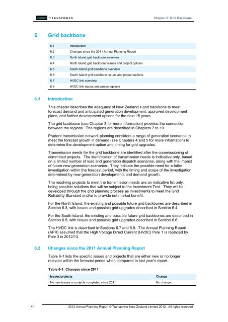
Chapter 6: <strong>Grid</strong> Backbone6 <strong>Grid</strong> <strong>backbone</strong>6.1 Introduction6.2 Changes since the 2011 Annual Planning Report6.3 North Island grid <strong>backbone</strong> overview6.4 North Island grid <strong>backbone</strong> issues and project options6.5 South Island grid <strong>backbone</strong> overview6.6 South Island grid <strong>backbone</strong> issues and project options6.7 HVDC link overview6.8 HVDC link issues and project options6.1 IntroductionThis chapter describes the adequacy of New Zealand’s grid <strong>backbone</strong> to meetforecast demand and anticipated generation development, approved developmentplans, and further development options for the next 15 years.The grid <strong>backbone</strong> (see Chapter 3 for more information) provides the connectionbetween the regions. The regions are described in Chapters 7 to 19.Prudent transmission network planning considers a range of generation scenarios tomeet the forecast growth in demand (see Chapters 4 and 5 for more information) todetermine the development option and timing for grid upgrades.Transmission needs for the grid <strong>backbone</strong> are identified after the commissioning ofcommitted projects. The identification of transmission needs is indicative only, basedon a limited number of load and generation dispatch scenarios, along with the impactof future new generation scenarios. They indicate the possible need for a fullerinvestigation within the forecast period, with the timing and scope of the investigationdetermined by new generation developments and demand growth.The resolving projects to meet the transmission needs are an indicative list only,being possible solutions that will be subject to the Investment Test. They will bedeveloped through the grid planning process as investments to meet the <strong>Grid</strong>Reliability Standard and/or to provide net market benefit.For the North Island, the existing and possible future grid <strong>backbone</strong>s are described inSection 6.3, with issues and possible grid upgrades described in Section 6.4.For the South Island, the existing and possible future grid <strong>backbone</strong>s are described inSection 6.5, with issues and possible grid upgrades described in Section 6.6.The HVDC link is described in Sections 6.7 and 6.8. The Annual Planning Report(APR) assumed that the High Voltage Direct Current (HVDC) Pole 1 is replaced byPole 3 in 2012/13.6.2 Changes since the 2011 Annual Planning ReportTable 6-1 lists the specific issues and projects that are either new or no longerrelevant within the forecast period when compared to last year's report.Table 6-1: Changes since 2011Issues/projectsNo new issues or projects completed since 2011ChangeNo change402012 Annual Planning Report © <strong>Transpower</strong> New Zealand Limited 2012. All rights reserved.
Chapter 6: <strong>Grid</strong> Backbone6.3 North Island grid <strong>backbone</strong> overview6.3.1 Existing North Island transmission configurationThe North Island grid <strong>backbone</strong> comprises the:220 kV circuits from Wellington to Auckland located along the Central NorthIsland corridor220 kV Wairakei Ring circuits (220 kV circuits between Wairakei andWhakamaru) connecting the major hydro and geothermal generation in theCentral North Island to the transmission network, and220 kV circuits from Bunnythorpe to Huntly through Stratford connecting Taranakigeneration to the transmission network.Power flows either north or south on the inter-island HVDC link, depending on thetime of day or year. During daylight periods and normal rainfall patterns in the SouthIsland, power tends to flow north. In non-peak periods (late evenings and earlymornings) and years of low South Island rainfall, power tends to flow south.Figure 6-1 shows a simplified schematic of the existing North Island grid <strong>backbone</strong>.2012 Annual Planning Report © <strong>Transpower</strong> New Zealand Limited 2012. All rights reserved. 41
Chapter 6: <strong>Grid</strong> BackboneFigure 6-1: North Island grid <strong>backbone</strong> schematicOtahuhuTakaniniGlenbrookDruryHuntlyOhinewaiHamiltonTe KowhaiWhakamaruAtiamuriOhakuriTaumarunuiPoihipiTokaanuWairakeiRangipoStratfordTangiwaiBrunswickBunnythorpeLintonKEY220 kV CIRCUIT220 kV SUBSTATION BUSHaywardsGENERATORCAPACITORTEE POINTWilton422012 Annual Planning Report © <strong>Transpower</strong> New Zealand Limited 2012. All rights reserved.
Chapter 6: <strong>Grid</strong> Backbone6.3.2 Future North Island grid <strong>backbone</strong>Figure 6-2 and Figure 6-3 provide an indication of the North Island transmission<strong>backbone</strong> development in the medium term (the next 15 years), and longer term(beyond 2027), respectively.We are building a new double-circuit transmission link from Whakamaru to Auckland,and a new double-circuit transmission line between Wairakei and Whakamaru.We have submitted an Investment Proposal to the Commerce Commission to replaceconductor on the existing 220 kV transmission lines between Bunnythorpe andHaywards. A consequence of the replacement will be to increase capacity on theselines.We will also investigate an increase in transmission capacity north of Bunnythorpe,either through the Central North Island to Whakamaru, and/or through the Taranakiregion and a new line to Whakamaru.In the longer term, we may increase the transmission capacity through the NorthIsland by increasing the operating voltage on the new overhead transmission line intoAuckland to 400 kV. Ultimately we may build a new transmission line connectingBunnythorpe, Whakamaru, and Auckland, but this is highly dependent on future loadand generation growth, and the viability of alternatives.We will also be looking to provide substation diversity at some critical transmissionnodes and strengthen resilience to high impact low probability events.Voltage stability in the Upper North Island is an ongoing issue. We will continue tostudy the additional reactive support requirements to maintain Upper North Islandvoltage stability as regional load continues to grow.2012 Annual Planning Report © <strong>Transpower</strong> New Zealand Limited 2012. All rights reserved. 43
Chapter 6: <strong>Grid</strong> BackboneFigure 6-2: Indicative North Island grid <strong>backbone</strong> schematic to 2027OtahuhuPakurangaGlenbrookTakaniniDruryBrownhill** new double circuit transmission line constructed for400 kV operation but initially operated at 220 kV.OhinewaiHuntlyHamiltonTe KowhaiWhakamaru BAtiamuriOhakuriTaumarunuiTokaanuWhakamaru ATe MihiPoihipiWairakeiRangipoStratfordTangiwaiBrunswickBunnythorpeLintonKEYNEW ASSETSUPGRADED ASSETSHaywardsWilton442012 Annual Planning Report © <strong>Transpower</strong> New Zealand Limited 2012. All rights reserved.
Chapter 6: <strong>Grid</strong> BackboneFigure 6-3: Longer term indicative North Island grid <strong>backbone</strong> schematicOtahuhuPakuranga400 kVTakanini220 kVBrownhill**GlenbrookDrury***400 kVAlthough this diagram shows a fewpossible development paths for thefuture North Island grid <strong>backbone</strong>transmission system, it is not intendedto indicate a preference. Any optionwill be finalised closer to the date thattransmission reinforcement is needed.OhinewaiHuntlyHamilton400 kV* Another possible option is a newHVDC link into Auckland.** New grid exit point(s) south ofOtahuhu, possibly:- north of Drury, and/or- at Brownhill Road by extending the220 kV bus.Te KowhaiWhakamaru BAtiamuriOhakuriTaumarunuiWhakamaru ATokaanuTe MihiPoihipiWairakeiRangipoStratfordTangiwaiBrunswickBunnythorpeKEYLintonNEW ASSETSUPGRADED ASSETSHaywardsWilton6.4 North Island grid <strong>backbone</strong> issues and project optionsThe North Island grid <strong>backbone</strong> comprises five areas indicated in Figure 6-4. Table6-2 summarises issues involving the grid <strong>backbone</strong> for the next 15 years. For moreinformation about a particular issue, refer to the listed section number in Table 6-2.2012 Annual Planning Report © <strong>Transpower</strong> New Zealand Limited 2012. All rights reserved. 45
Chapter 6: <strong>Grid</strong> BackboneFigure 6-4: North Island grid <strong>backbone</strong> areaUpper NorthIsland areaWairakei Ring areaTaranaki areaCentral NorthIsland areaWellington areaTable 6-2: <strong>Grid</strong> <strong>backbone</strong> transmission issuesSectionnumberIssue6.4.1 Upper North Island voltage stability6.4.2 Transmission capacity into Auckland and Northland6.4.3 Wairakei Ring transmission capacity6.4.4 Taranaki transmission capacity6.4.5 Central North Island transmission capacity6.4.6 Wellington area transmission capacity6.4.1 Upper North Island voltage stabilityOverviewThe Upper North Island covers the geographical area north of Huntly, includingGlenbrook, Takanini, Auckland, and the North Isthmus.The transmission capability to supply the Upper North Island load is limited by voltagestability, which in turn is influenced by:generation in Auckland and at Huntlythe reactive power losses due to the transmission system within the Upper NorthIslandthe reactive power losses due to the transmission system supplying the UpperNorth Island area, andthe reactive power demand due to the composition of the load in the area (inparticular the proportion and type of motor load).There are several generator and circuit contingencies that can cause voltage controlproblems. The worst contingencies include the loss of the:462012 Annual Planning Report © <strong>Transpower</strong> New Zealand Limited 2012. All rights reserved.
Chapter 6: <strong>Grid</strong> BackboneOtahuhu combined-cycle gas turbine generatorHuntly E3P generator (Unit 5)220 kV Huntly–Otahuhu 2 circuit, or220 kV Drury–Huntly 1 circuit.The Upper North Island load includes a significant proportion of motor load. Thebehaviour of this load during and following faults influences the regional transmissionvoltage performance. During a severe fault, motors will decelerate and some canstall. The motors will then draw large currents which in turn delay the voltagerecovery after a fault. We have identified that voltage recovery is most at risk in latesummer between mid-January and mid-March, when the greatest amount of motorload is connected.Reactive losses on heavily loaded transmission lines are significant, especiallyfollowing a circuit tripping when the loading of parallel circuits increases.The Upper North Island has an enduring need for voltage support because of itsreliance on long transmission lines from the south for much of its power. Investmentis required every two or three years for voltage support in the Upper North Island.Some component of reactive power support in the Auckland region must be dynamicto avoid the need for shunt capacitor switching after a transmission or generatorcontingency. The dynamic reactive support may be provided by generators,synchronous condensers, static var compensators (SVCs) or static synchronouscompensators (STATCOMs).Approved projectsInvestments in previous years include an SVC at Albany, binary switched capacitorsat Kaitaia, ten capacitor banks totalling 600 Mvar at four substations 12 , and ashort-term contract for reactive support from condensers at Otahuhu 13 . Sixcapacitors are, or soon will be, decommissioned 14 based on condition assessment.We have installed power system monitoring equipment to improve our understandingof the Upper North Island power system, specifically load composition and responseto transient events.Projects approved in 2010 by the Electricity Commission under Part F of theElectricity Governance Rules include:a STATCOM at Penrose, scheduled for commissioning in 2013two STATCOMs at Marsden, scheduled for commissioning in 2014a Reactive Power Controller (RPC) to co-ordinate the various dynamic and staticdevices in the Upper North Island. This work is scheduled to begin in 2012, forcommissioning in 2014/2015, anddemand-side participation.We issued a Request For Proposals for demand-side participation, but the proposalsreceived were all uneconomic. This was an unexpected result, and the demand-sideparticipation framework is being further developed to unlock its potential (see Section2.2 for more information).Other approved projects also have a beneficial effect on voltage stability in the UpperNorth Island by reducing the reactive power losses in the transmission system.121314Capacitors installed in previous years are: Albany 1 x 100 Mvar, Hepburn Road 3 x 50 Mvar,Penrose 4 x 50 Mvar, Otahuhu 2 x 100 Mvar.The condensers belong to Contact Energy, and were once operated as gas turbine generators, Thecontract for the condensers expires in 2013 and will not be renewed, as it is more economic to installother reactive support such as STATCOMs.Capacitors that are, or soon will be, decommissioned are: Albany 2 x 30 Mvar, Henderson1 x 30 Mvar, and Otahuhu 3 x 30 Mvar.2012 Annual Planning Report © <strong>Transpower</strong> New Zealand Limited 2012. All rights reserved. 47
Chapter 6: <strong>Grid</strong> BackboneThe North Auckland and Northland (NAaN) project that increases thetransmission capacity in the Auckland and Northland regions (see Chapter 7,Section 7.8.4 for more information).The North Island <strong>Grid</strong> Upgrade (NIGU) project that increases the transmissioncapacity into the Auckland and Northland regions (see Section 6.4.2 for moreinformation).Even with these approved projects, voltage stability will be an ongoing issue.Resolving projectsWe have commenced an investigation to determine the amount of additional reactivesupport required to relieve the Upper North Island voltage stability issue beyond thecompletion of the NAaN and NIGU projects.Additional reactive support will be required about every two-three years. This will bea mixture of capacitors and dynamic support such as STATCOMs. The benefits ofadvancing series compensation on the new transmission link between Whakamaruand Pakuranga will be evaluated also.The project cost falls within band E. This is a possible investment project to meet the<strong>Grid</strong> Reliability Standard and we anticipate seeking approval from the Commission inthe second half of 2012.6.4.2 Transmission capacity into Auckland and NorthlandOverviewPower transfer to the Upper North Island is dependent on:the generation from Huntly, and the transmission capacity between Huntly andOtahuhu, andgeneration from Whakamaru and south of Whakamaru, and the transmissioncapacity between Whakamaru and Otahuhu.For the existing system, issues that may arise during periods of high demand and lowgeneration in the Auckland area include:an outage of a Huntly–Otahuhu circuit may overload the other Huntly–Otahuhucircuit.an outage of a Huntly–Ohinewai circuit may overload the other Huntly–Ohinewaicircuit.the two 220 kV Otahuhu–Whakamaru circuits may overload during a contingency.an outage of the Hamilton–Whakamaru circuit may overload the two 110 kVArapuni–Hamilton regional circuits.an outage of the Hamilton–Ohinewai circuit may cause low voltage at theHamilton 220 kV bus.Approved projectsThe above issues will be addressed by the North Island <strong>Grid</strong> Upgrade (NIGU). NIGUincludes a number of projects which will:increase the power transfer capacity into Aucklandreduce the loading on the existing 220 kV Otahuhu–Whakamaru and Huntly–Otahuhu circuits, andreduce the reactive support needed in the Upper North Island (see Section 6.4.1).482012 Annual Planning Report © <strong>Transpower</strong> New Zealand Limited 2012. All rights reserved.
Chapter 6: <strong>Grid</strong> BackboneAs part of NIGU, we have just completed conversion of the existing 110 kVPakuranga substation to 220 kV, and the existing Otahuhu–Pakuranga line from110 kV to 220 kV operation 15 .The remaining NIGU projects include:a new substation, Whakamaru B (near the existing Whakamaru substation) and atransition station at Brownhilla double-circuit overhead transmission line approximately 190 km fromWhakamaru B substation to a transition station at Brownhill, which will:• initially operate at 220 kV, and• be capable of 400 kV operation in future.two 220 kV underground cables from the transition station at Brownhill toPakuranga substation, rated at 851/890 MVA summer/winter per cable circuit.After the commissioning of the NIGU projects, eight 220 kV circuits from the south willprimarily supply the Upper North Island, with three diverse routes, comprising:two circuits from Huntly to Otahuhu (the western path)four circuits from Whakamaru to Otahuhu (the central path), andtwo circuits from Whakamaru to Pakuranga (the eastern path).There are also two circuits between Huntly and Ohinewai connecting the western andcentral paths.There is a 220 kV connection between Otahuhu and Pakuranga within the Aucklandregion. The North Auckland and Northland (NAaN) project makes use of thetransmission capacity and diversity provided by Pakuranga to increase the capacityand security within the Auckland and Northland regions (see Chapter 7, Section7.8.4).The Auckland region is also connected by two smaller 110 kV regional circuits fromArapuni via Hamilton, Bombay, and Wiri to Otahuhu, though their contribution isminor compared to the 220 kV circuits.Figure 6-5 shows the grid <strong>backbone</strong> circuits supplying the Upper North Island area.15The Otahuhu–Pakuranga line was constructed at 220 kV, but operated initially at 110 kV.2012 Annual Planning Report © <strong>Transpower</strong> New Zealand Limited 2012. All rights reserved. 49
Chapter 6: <strong>Grid</strong> BackboneFigure 6-5: 220 kV Upper North Island grid <strong>backbone</strong> circuitsOtahuhuPakurangaGlenbrookTakaniniDruryBrownhill** new double circuittransmission line constructedfor 400 kV operation butinitially operated at 220 kV.OhinewaiCircuitDrury–Huntly 1Drury–Glenbrook 1 and 2Drury–Takanini–Otahuhu 1Huntly–Ohinewai 1 and 2Huntly–Takanini 2Hamilton–Ohinewai 1Hamilton–Whakamaru 1Ohinewai–Otahuhu 1 and 2Ohinewai–Whakamaru 1Otahuhu–Whakamaru 1 and 2Otahuhu–Takanini 2Pakuranga–Whakamaru North 1 and 2HuntlyHamiltonSummer/Winterrating694/764 MVA694/762 MVA1123/1200 MVA694/764 MVA694/764 MVA615/671 MVA615/671 MVA615/671 MVA615/671 MVA293/323 MVA678/724 MVA851/890 MVAWhakamaru BWhakamaru AThe following sections assess the transmission capability of the circuits into theAuckland and Northland regions following the committed NIGU projects. Theassessment is based on representative system conditions, to determine how differentgeneration development scenarios interact with the circuits into Auckland andNorthland.System condition 1 (normal summer’s day demand)This system condition tests a low generation scenario in the Auckland and Northlandregion during a normal demand period:normal summer’s day load in the North Island (approximately 85% of summerpeak load)no thermal generation in Auckland and Northland in servicelow renewable generation in Auckland and Northland, andmedium to high generation elsewhere.The circuits into the Auckland and Northland regions have sufficient capacity during anormal demand period and low generation in the Auckland and Northland regions forthe duration of the forecast period.System condition 2 (peak demand)This system condition tests a high demand period in the Auckland and Northlandregions along with the outage of the biggest generator:island peak load in the North Islandhigh generation in the North Islandthe biggest generator in Auckland is out of service, i.e. Otahuhu C or Huntly E3P,and502012 Annual Planning Report © <strong>Transpower</strong> New Zealand Limited 2012. All rights reserved.
Chapter 6: <strong>Grid</strong> Backboneall other thermal generation in Auckland, Northland and Huntly 16 is in service.Through this it was identified that the Hamilton bus voltage may fall below 0.9 p.u. forthe loss of the Hamilton–Ohinewai circuit towards the end of the forecast period.Impact of generation scenariosThe five generation scenarios described in Chapter 5 have the following impacts onthe circuits into Auckland and Northland.For system condition 1, all the generation scenarios have minimal impact within theforecast period.For system condition 2, a low Hamilton bus voltage is seen towards the end of theforecast period in generation scenarios 1 (‘sustainable path’) and 2 (‘South Islandwind’). This is because compared to the other generation scenarios, a lower amountof generation is commissioned in the Northland, Auckland and Waikato regions inthese scenarios.OutagesAn outage of one of the circuits into Auckland and an outage of the biggest generatorin Auckland still maintains n-1 security into Auckland and Northland.Resolving projectsWe will investigate options to resolve the Hamilton bus voltage issue closer to thetime it occurs (see Chapter 9, Section 9.9.2 for more information).Beyond 15 years, the double-circuit line from Whakamaru B to Brownhill will beconverted from 220 kV to its construction voltage of 400 kV. This will also require:220/400 kV transformers and associated works at Whakamaru B substation tointerconnect with the existing 220 kV systema switchyard in the vicinity of the transition station at Brownhill with 220/400 kVtransformers and associated works220 kV underground cables to the Otahuhu substation, andextensions to the Otahuhu switchyard(s).6.4.3 Wairakei Ring transmission capacityOverviewThe Wairakei Ring circuits:connect the major hydro and geothermal generation stations in the North Islandto the grid <strong>backbone</strong>, andsupply the Bay of Plenty region from Atiamuri and Ohakuri.In addition, a new geothermal power station is being built at Te Mihi, and a number ofother generation stations which connect directly or indirectly to the Wairakei Ring arein the planning or consent stage.For the existing system, as this generation develops, an outage of one of theWairakei Ring circuits may begin to constrain north power flows. Specifically, anoutage of the:Whakamaru–Poihipi–Wairakei circuit may overload the Wairakei–Ohakuri–Atiamuri circuits16At Huntly, all generator units are in service except E3P is placed out of service for the study. In the 5generation scenarios, there are new generation connected at Huntly and some units aredecommissioned. It ranges from 630 MW to 1,295 MW in 2027 across the 5 generation scenarios.2012 Annual Planning Report © <strong>Transpower</strong> New Zealand Limited 2012. All rights reserved. 51
Chapter 6: <strong>Grid</strong> BackboneWairakei–Ohakuri–Atiamuri circuits may overload the Whakamaru–Poihipi–Wairakei circuit.Approved projectsTo address the above issues, we are building a 220 kV double-circuit line betweenWairakei and Whakamaru, to replace the existing single-circuit Wairakei–WhakamaruB line. The line is scheduled for commissioning in 2013, and will increase the powerflow capacity through the Wairakei Ring.Figure 6-6 shows the grid <strong>backbone</strong> circuits in the Wairakei Ring area after thecommissioning of the Wairakei Ring project.Figure 6-6: 220 kV Wairakei Ring circuitsWhakamaru BAtiamuriCircuitOhakuri–Wairakei 1Atiamuri–Ohakuri 1Atiamuri–Whakamaru 1Wairakei–Whakamaru 1Wairakei–Te Mihi–Whakamaru 1OhakuriSummer/Winterrating333/358 MVA333/358 MVA333/358 MVA903/994 MVA903/994 MVAWhakamaru ATe MihiPoihipiWairakeiThe following sections assess the Wairakei Ring transmission capability following thecommitted Wairakei to Whakamaru Replacement Line Project. The assessment isbased on representative system conditions, to determine how different generationdevelopment scenarios interact with the Wairakei Ring.System condition 1 (north flow)This system condition tests power flowing north through the circuits in the WairakeiRing towards the Upper North Island:island peak load in the North Islandhigh geothermal generation in the Wairakei Ring areamedium to high generation (including peakers) elsewhere to balance generationwith demand, andHVDC north transfer between 380 MW and, but not exceeding, 1,400 MW.The following issues were identified:The Atiamuri–Ohakuri and Ohakuri–Wairakei circuits may overload for an outageof either the new Te Mihi–Whakamaru or Wairakei–Whakamaru circuits.High generation at Kawerau and low demand in the Bay of Plenty may causehigher circuit loading on the Atiamuri–Ohakuri circuit especially during high northflow through the Wairakei Ring circuits. In this scenario, the Atiamuri–Ohakuricircuit may also overload for an outage of the Edgecumbe–Kawerau circuit.System condition 2 (south flow)This system condition tests power flowing south through the circuits in the WairakeiRing towards the Wellington region and the South Island via the HVDC link:522012 Annual Planning Report © <strong>Transpower</strong> New Zealand Limited 2012. All rights reserved.
Chapter 6: <strong>Grid</strong> Backbonelow North Island load (approximately 45% of peak load)high geothermal generation in the Wairakei Ring areamedium to low generation elsewhere, andHVDC south transfer but not exceeding 950 MW.The Wairakei Ring circuits have sufficient capacity for south power flows for theduration of the forecast period. However, there may be transmission constraintssouth of the Wairakei Ring (see Section 6.4.5).System condition 3 (east flow)This system condition tests the ability of the Wairakei Ring circuits to supply the Bayof Plenty region during high demand and medium generation in that region:island peak load in North Islandhigh geothermal generation in the Wairakei Ring areamedium generation in the Bay of Plenty region with the biggest generator in theregion out of service (Kawerau geothermal generator is out of service).medium to high generation (including peakers) elsewhere to balance generationwith demand, andHVDC north transfer but not exceeding 1,400 MW.The following circuits may overload for this system condition.The Ohakuri–Wairakei circuit overloads for an outage of the Atiamuri–Whakamaru, Te Mihi–Whakamaru or Wairakei–Whakamaru circuits.The Atiamuri–Ohakuri circuit overloads for an outage of the Atiamuri–Whakamaru, Te Mihi–Whakamaru or Wairakei–Whakamaru circuits.The Atiamuri–Whakamaru circuit overloads for an outage of the Ohakuri–Wairakei circuit.Impact of generation scenariosThe five generation scenarios described in Chapter 5 have the following impacts onthe circuits in the Wairakei Ring.For system condition 1 (north power flow through the Wairakei Ring circuits to supplythe Upper North Island), only generation scenarios 1 (‘sustainable path’) and 3(‘medium renewables’) have a significant impact. These generation scenarios havethe lowest net increase in the Upper North Island generation compared to the othergeneration scenarios. Therefore, there are higher levels of power flow through theWairakei Ring to supply the Upper North Island load, which may overload theAtiamuri–Ohakuri and Ohakuri–Wairakei circuits.Generation scenario 1 (‘sustainable path’) has the highest net increase in generationin the Bay of Plenty region compared to the other generation scenarios. Highgeneration and low demand in the Bay of Plenty region may cause the Atiamuri–Ohakuri circuit to overload in a contingent event.For system condition 2 (south power flow through the Wairakei Ring circuits), all thegeneration scenarios have minimal impact on the Wairakei Ring circuits within theforecast period.For system condition 3 (east power flow through the Wairakei Ring), generationscenarios 2 (‘South Island wind’) and 5 (‘high gas discovery’) have the highest impacton circuits supplying the Bay of Plenty region. These generation scenarios have thelowest net increase in generation in the Bay of Plenty region. Therefore, there arehigher levels of power flow through the Wairakei Ring to supply the Bay of Plenty,which may overload the Wairakei–Ohakuri–Atiamuri–Whakamaru circuits.2012 Annual Planning Report © <strong>Transpower</strong> New Zealand Limited 2012. All rights reserved. 53
Chapter 6: <strong>Grid</strong> BackboneOutagesThe main connection to the Bay of Plenty region is through the Wairakei–Ohakuri andAtiamuri–Whakamaru circuits. An outage of either of these circuits puts the wholeBay of Plenty region on n security.All outages within the Wairakei Ring may also cause generation constraints, whichrequire replacement generation in other areas such as the Auckland region.Resolving projectsDuring peak demand periods in the Bay of Plenty region, generation must run in theregion to prevent overloading of the Wairakei–Ohakuri–Atiamuri–Whakamaru circuits.Historically, generation in the Bay of Plenty region has been available during peakperiods, and we expect this will continue in the short term. However, in the longerterm, the region’s dependence on local hydro generation may expose it to insufficienttransmission capacity within the Wairakei Ring in dry years.Transmission solutions to prevent overloading of the Wairakei–Ohakuri–Atiamuri–Whakamaru circuits include:variable line ratings, which will alleviate some of the overloads in the short termreconductoring the Wairakei–Ohakuri–Atiamuri circuits, followed by the Atiamuri–Whakamaru circuit, if required, ora new 220 kV Wairakei–Atiamuri circuit (bypassing Ohakuri), followed by asecond Atiamuri–Whakamaru circuit, if required.The Wairakei–Ohakuri–Atiamuri–Whakamaru circuits have already been thermallyupgraded, and a further thermal upgrade is not technically feasible. A secondWairakei–Atiamuri circuit is one option which keeps the Bay of Plenty region on n-1security during outages of the Wairakei–Ohakuri or Atiamuri–Whakamaru circuits. Itis unlikely that security to the Bay of Plenty during outages will by itself providesufficient benefit to justify the second circuit.We will monitor the generation developments in the Wairakei Ring area and the Bayof Plenty region, to determine if a transmission upgrade investigation is required.6.4.4 Taranaki transmission capacityOverviewTaranaki generation is connected to the North Island grid <strong>backbone</strong> via Stratford withtwo 220 kV circuits north to Huntly and two circuits south to Bunnythorpe.Figure 6-7 shows the grid <strong>backbone</strong> circuits for the Taranaki area betweenBunnythorpe and Huntly.542012 Annual Planning Report © <strong>Transpower</strong> New Zealand Limited 2012. All rights reserved.
Chapter 6: <strong>Grid</strong> BackboneFigure 6-7: 220 kV circuits between Bunnythorpe and HuntlyHuntlyTe KowhaiStratfordTaumarunuiCircuitSummer/WinterratingBunnythorpe–Brunswick 1 and 2 695/712 MVA 1Brunswick–Stratford 1 and 3239/292 MVABrunswick–Stratford 2232/287 MVAHuntly–Stratford 1 354/354 MVA 1Stratford–Taumarunui 1 (from Stratford) 455/455 MVA 2Stratford–Taumarunui 1 (from Taumarunui) 343/343 MVA 2Taumarunui–Te Kowhai 1469/492 MVAHuntly–Te Kowhai 1 (from Huntly) 301/301 MVA 2Huntly–Te Kowhai (from Te Kowhai) 469/492 MVA 21. This rating is due to a component other than the conductor.2. The circuit rating depends on the direction of power flow. This is due toprotection settings.BrunswickBunnythorpeApproved projectsThere are no approved grid <strong>backbone</strong> projects in the Taranaki area.The following sections assess the Taranaki transmission capability following thecommitted upgrades in the North Island. The assessment is based on representativesystem conditions, to determine how different generation development scenariosinteract with the circuits out of Taranaki.System condition 1 (north flow)This system condition tests power flowing north through the circuits between Stratfordand Huntly to Auckland and Northland:island peak load in the North Islandhigh generation in Taranakithe biggest generator in Auckland is out of service i.e. Otahuhu Cmedium to high generation elsewhere to balance generation with demand, andHVDC north transfer varies between 380 MW and 1,400 MW depending ongeneration and demand in the North Island.For this system condition, an outage of one of the Huntly–Stratford circuits may causethe other circuit to overload especially during high Taranaki generation and lowAuckland generation. Also, an outage of one of the Huntly–Stratford circuits maylead to dynamic and transient instability during high Taranaki generation.2012 Annual Planning Report © <strong>Transpower</strong> New Zealand Limited 2012. All rights reserved. 55
Chapter 6: <strong>Grid</strong> BackboneFor high levels of generation in the Taranaki area, power also flows to Bunnythorpebefore flowing north through the Central North Island grid <strong>backbone</strong> 17 .System condition 2 (south flow)This system condition tests power flowing mainly south through the circuits betweenStratford and Bunnythorpe to the HVDC link:low North Island load (approximately 45% of peak load)high generation in Taranakimedium to low generation elsewhere to balance generation with demand, andHVDC varies between 120 MW north transfer and 950 MW south transferdepending on generation and demand in the North Island.For this system condition, an outage of one of the Brunswick–Stratford circuits mayoverload the remaining two Brunswick–Stratford circuits 18 and the parallel 110 kVcircuits between Stratford and Bunnythorpe.The 110 kV circuits that overload are mainly the Hawera–Stratford andWanganui–Waverly circuits, which have been upgraded to a higher rated conductorbut the ratings are still limited by substation equipment.Impact of generation scenariosThe five generation scenarios described in Chapter 5 have the following impacts onthe circuits out of Taranaki.For system condition 1 (north power flow from Stratford to Huntly), generationscenario 3 (‘medium renewables’) has the highest impact at the end of the forecastperiod, as it has the lowest net increase in generation in the Auckland and Northlandarea compared to the other generation scenarios. The significant overloads on theHuntly–Stratford circuits are dependent on:Auckland and Northland loadAuckland and Northland generation, andTaranaki generation.For system condition 2 (south power flow from Stratford to Bunnythorpe), all thegeneration scenarios have minimal impact within the forecast period on the Taranakitransmission capacity except for generation scenario 5 (‘high gas discovery’).Generation scenarios 1 to 4 include the decommissioning of the Taranaki combinedcyclegas turbine while generation scenario 5 does not. This scenario has a netincrease of up to 460 MW of new gas-fired peakers and combined-cycle gas turbines.OutagesAn outage of any of the circuits out of Taranaki i.e. between Stratford and Huntly orbetween Stratford and Bunnythorpe, may cause generation constraints, which requirereplacement generation in other areas.Resolving projectsTo prevent overloads on the circuits out of Taranaki during HVDC north and southflow, the Taranaki generation can be constrained. Alternatively, transmissionsolutions could include:1718Central North Island 220 kV circuits such as Tokaanu–Whakamaru may overload during highTaranaki generation and HVDC north flow. See Section 6.4.5 for more information about this issue.Central North Island 220 kV circuits such as Bunnythorpe–Tokaanu and Bunnythorpe–Tangiwai mayoverload before the Brunswick–Stratford circuits overload for high HVDC south flow. See Section6.4.5 for more information about this issue.562012 Annual Planning Report © <strong>Transpower</strong> New Zealand Limited 2012. All rights reserved.
Chapter 6: <strong>Grid</strong> BackboneSystem condition 1 (north flow)This system condition tests power flowing north through the circuits in the CentralNorth Island towards Whakamaru or Wairakei:island peak load in the North Islandhigh renewable generation including wind, wave, tidal, and solarmedium to high generation (including peakers) elsewhere to balance generationwith demand, andHVDC north transfer varies between 50 MW and 1,400 MW depending on NorthIsland generation and demand.For high generation in the Taranaki area, some of the Taranaki generation flows intoBunnythorpe. This can cause an overload on the Central North Island circuits.The following circuits may overload for this system condition.A Tokaanu–Whakamaru circuit may overload for an outage of the otherTokaanu–Whakamaru circuit, any of the Bunnythorpe–Tangiwai–Rangipo–Wairakei circuits, or one of the circuits between Stratford and Huntly.A Bunnythorpe–Tokaanu circuit may overload for an outage of the otherBunnythorpe–Tokaanu circuit, any section of the Bunnythorpe–Tangiwai–Rangipo–Wairakei circuit, or one of the circuits between Stratford and Huntly.The Bunnythorpe–Tangiwai–Rangipo–Wairakei circuits may overload for anoutage of one of the Bunnythorpe–Tokaanu–Whakamaru circuits or one of thecircuits between Stratford and Huntly.There is a regional 110 kV single circuit between Bunnythorpe and Arapuni (viaMataroa, Ohakune, and Ongarue) which may also overload and constrain northtransfer.System condition 2 (south flow)This system condition tests power flowing south through the circuits in the CentralNorth Island towards Bunnythorpe:low North Island load (approximately 45% of peak load)low renewable generation including wind, wave, tidal, and solarhigh geothermal generation in the Wairakei Ring arealow to medium generation elsewhere to balance generation with demand, andHVDC south transfer varies between 580 MW and 950 MW depending on NorthIsland generation and demand.The following circuits may overload for this system condition.A Bunnythorpe–Tokaanu circuit may overload for an outage of the otherBunnythorpe–Tokaanu circuit or any section of the Bunnythorpe–Tangiwai–Rangipo–Wairakei circuit.A Tokaanu–Whakamaru circuit may overload for an outage of the otherTokaanu–Whakamaru circuit, any section of the Bunnythorpe–Tangiwai–Rangipo–Wairakei circuits, or one of the circuits between Stratford and Huntly.The Bunnythorpe–Tangiwai–Rangipo–Wairakei circuit may overload for outagesof a Bunnythorpe–Tokaanu–Whakamaru circuit or one of the circuits betweenStratford and Huntly.There is also low voltage at Bunnythorpe, Tangiwai, and Tokaanu for high HVDCsouth transfer and low generation in the Lower North Island.The regional 110 kV circuit between Bunnythorpe and Arapuni (via Mataroa,Ohakune, and Ongarue) may also overload and constrain HVDC south transfer.582012 Annual Planning Report © <strong>Transpower</strong> New Zealand Limited 2012. All rights reserved.
Chapter 6: <strong>Grid</strong> BackboneImpact of generation scenariosThe five generation scenarios described in Chapter 5 have the following impacts onthe Central North Island circuits.For system condition 1 (north power flow from Bunnythorpe to Whakamaru/Wairakei),generation scenario 3 (‘medium renewables’) has the highest impact on the circuits inthe Central North Island, as it has the lowest net increase in generation in theAuckland and Northland area compared to the other generation scenarios.For system condition 2 (south power flow from Whakamaru/Wairakei to Bunnythorpe),generation scenarios 4 (‘coal’) and 5 (‘high gas discovery’) have the highest impacton the circuits in the Central North Island, as they have the lowest net increase ingeneration in the Wellington area. With a lower amount of new generation in theWellington area, more power is required to flow through the circuits betweenWhakamaru/Wairakei and Bunnythorpe to supply the demand in the Wellington areaand the South Island via the HVDC link. Low voltage at Bunnythorpe, Tangiwai, andTokaanu only occurs for generation scenario 4, which has the lowest net increase ingeneration in the Lower North Island.OutagesAn outage of any of the Central North Island circuits may cause generationconstraints, which require replacement generation in other areas.Resolving projectsFor the circuits between Whakamaru and Bunnythorpe, the requirement to upgrade islargely dictated by generation development in the area. The upgrade options can beseparated into two tranches depending on the amount of new generation.In tranche 1, the range of options includes:limit the power flow on 110 kV regional network between Mataroa and Ohakunethrough a Special Protection Scheme (SPS), series reactor, phase shiftingtransformer or a permanent system split (putting four regional grid exit points on nsecurity)reconductor the Tokaanu–Whakamaru circuits, andthermally upgrade or reconductor the Bunnythorpe–Tangiwai–Rangipo circuit.Tranche 1 options may enable up to 500 MW of new generation connected at or nearto Bunnythorpe. The project cost falls within band F.In tranche 2, the range of options will enable more generation beyond the options fortranche 1. The range of options includes:reconductor the Bunnythorpe–Tokaanu circuitsprovide new transmission capacity between Bunnythorpe and Whakamaru:• reuse the existing 220 kV single circuit line route between Bunnythorpe andWairakei for a replacement double-circuit• a new double-circuit 220 kV or 400 kV circuit between Bunnythorpe andWhakamaru, or• HVDC light between Bunnythorpe and Whakamaru.a new line in the Taranaki area, from Taumarunui to Whakamaru (to divert powerflow from the Central North Island grid <strong>backbone</strong>), andLower North Island-wide System Protection Scheme to enable new generation.The details and range of options in tranche 2 are still being investigated.2012 Annual Planning Report © <strong>Transpower</strong> New Zealand Limited 2012. All rights reserved. 59
Chapter 6: <strong>Grid</strong> BackboneWe will monitor generation developments in the Central North Island area, todetermine the level of transmission upgrades required including the need for reactivedevices to alleviate the low voltage issues.6.4.6 Wellington area transmission capacityOverviewThe 220 kV circuits in the Wellington area between Bunnythorpe and Wellingtoncomprise:two circuits connecting directly between Haywards and Bunnythorpeone Haywards–Linton–Bunnythorpe circuit, with Tararua Wind Central connectedoff the Linton–Bunnythorpe section of the circuit, andone Wilton–Linton–Bunnythorpe circuit.Figure 6-9 shows the grid <strong>backbone</strong> circuits in the Wellington area.Figure 6-9: 220 kV circuits in the Wellington areaBunnythorpeLintonHaywardsCircuitBunnythorpe–Haywards 1 and 2Bunnythorpe–Linton–Wilton 1Bunnythorpe–Tararua Wind Central–Linton 1Haywards–Linton 1Haywards–Wilton 1Summer/Winterrating307/335 MVA694/764 MVA694/764 MVA694/762 MVA694/739 MVAWiltonApproved projectsThere are no approved grid <strong>backbone</strong> projects for the Wellington area.We submitted an Investment Proposal to the Commerce Commission in December2011 to reconductor the two direct Bunnythorpe–Haywards circuits because ofcondition assessment. The replacement conductor will also provide a small increasein the circuits’ rating (from 307/335 MVA to 355/370 MVA). A decision from theCommerce Commission is expected in the second quarter of 2012.The project cost falls within band F and construction is expected to be completed bythe fourth quarter of 2018.The following sections assess the Wellington area’s transmission capability followingthe committed upgrades in the North Island. The assessment is based onrepresentative system conditions, to determine how different generation developmentscenarios interact with the circuits in the Wellington area.System condition 1 (HVDC north flow)This system condition tests power flowing north through the circuits in the Wellingtonarea towards Bunnythorpe:island peak load in the North Islandhigh renewable generation including wind, wave, tidal, and solarmedium to high generation (including peakers) elsewhere to balance generationwith demand, and602012 Annual Planning Report © <strong>Transpower</strong> New Zealand Limited 2012. All rights reserved.
Chapter 6: <strong>Grid</strong> BackboneHVDC north transfer varies between 50 MW and 1,400 MW depending on NorthIsland generation and demand.The following circuits may overload for this system condition.The two Bunnythorpe–Haywards circuits may overload for outages of theHaywards–Linton–Bunnythorpe circuit (with Tararua Wind Central tee connected)or the Wilton–Linton–Bunnythorpe circuit.The Linton–Bunnythorpe circuit (with Tararua Wind Central tee connected) mayoverload for outages of the Haywards–Wilton circuit or the Wilton–Linton–Bunnythorpe circuit.The Haywards–Linton circuit may overload for an outage of the Linton–Bunnythorpe circuit (with Tararua Wind Central tee connected) under certaingeneration scenarios.The Wilton–Linton–Bunnythorpe circuit may overload for an outage of theHaywards–Wilton circuit under certain generation scenarios.System condition 2 (HVDC south flow)This system condition tests power flowing south through the circuits in the Wellingtonarea towards Haywards and Wilton:low North Island load (approximately 45% of peak load)low renewable generation including wind, wave, tidal, and solarhigh geothermal generation in the Wairakei Ring areamedium to low generation elsewhere, andHVDC south varies between 580 MW and 950 MW depending on North Islandgeneration and demand.For this system condition, the two Bunnythorpe–Haywards circuits may overload foroutages of the Haywards–Linton–Bunnythorpe circuit (with Tararua Wind Central teeconnected) or the Wilton–Linton–Bunnythorpe circuit.Some regional 110 kV circuits may also overload and constrain HVDC south transfer.These are the circuit between Bunnythorpe and Arapuni (via Mataroa, Ohakune, andOngarue) and the two Bunnythorpe–Woodville circuits.There are also voltage issues for the loss of a 220 kV circuit between Bunnythorpeand Wellington during high HVDC south transfer and low generation in the Wellingtonarea.Impact of generation scenariosThe five generation scenarios described in Chapter 5 have the following impacts onthe circuits in the Wellington area.For system condition 1 (north power flow from Wellington to Bunnythorpe), generationscenario 3 (‘medium renewables’) has the highest impact on the circuits in theWellington area, as it has the lowest net increase in generation in the Auckland andNorthland area compared to the other generation scenarios. Generation scenarios 1(‘sustainable path’) and 2 (‘South Island wind’) have high wind generation at theLinton bus and may cause the Haywards–Linton circuit to overload for outages of theLinton–Bunnythorpe circuit, Haywards–Wilton circuit or the Wilton–Linton–Bunnythorpe circuit. The Wilton–Linton–Bunnythorpe circuits may also overload dueto high generation at the Linton bus for an outage of the Haywards–Wilton circuit.For system condition 2 (south power flow from Bunnythorpe to Wellington),generation scenarios 4 (‘coal’) and 5 (‘high gas discovery’) have the highest impacton the circuits in the Wellington area, as they have the lowest net increase ingeneration in the Wellington area. With a lower amount of new generation inWellington, more power is required to flow through the circuits between Bunnythorpe2012 Annual Planning Report © <strong>Transpower</strong> New Zealand Limited 2012. All rights reserved. 61
Chapter 6: <strong>Grid</strong> Backboneand Wellington to supply Wellington area demand and the South Island via the HVDClink. Low voltages at Bunnythorpe and Linton occur only in generation scenario 4,which has the lowest net increase in generation in the Wellington area.OutagesAn outage of any of the 220 kV circuits in the Wellington area during HVDC north orsouth flow may cause generation constraints, which require replacement generationin other areas.Resolving projectsFor the two direct circuits between Bunnythorpe and Haywards, we believe that it isuneconomic to increase their rating to increase the transmission capacity (other thanthe small increase in rating following reconductoring – refer to Approved projectsabove). However, a higher amount of power transfer between Bunnythorpe andHaywards is possible with a Special Protection Scheme (SPS). The SPS willautomatically reduce the power flowing on the HVDC link (after Pole 3 iscommissioned) if the two direct Bunnythorpe–Haywards circuits overload, subject toother constraints within the power system. We will monitor the level of constraintcaused by these circuits to determine when an investigation to implement an SPS isrequired.The overloads on the two circuits between Bunnythorpe and Linton are driven by theamount of generation connected at Linton. We will monitor the amount of generationbeing connected at Linton to determine if a transmission upgrade investigation isrequired.For the two regional 110 kV Bunnythorpe–Woodville circuits, we have a committedproject to install an SPS to increase south flow transmission capacity. We willmonitor new generation connections to determine if an investigation to re-conductorthe circuits to a higher rating is required.There is significant potential wind generation in the Wairarapa. One option toconnect this generation is to build a new 220 kV transmission line from the Wairarapato Bunnythorpe or Linton.622012 Annual Planning Report © <strong>Transpower</strong> New Zealand Limited 2012. All rights reserved.
Chapter 6: <strong>Grid</strong> Backbone6.5 South Island grid <strong>backbone</strong> overview6.5.1 Existing South Island transmission configurationThe South Island grid <strong>backbone</strong> comprises 220 kV circuits with:three circuits from Islington to Kikiwafour circuits from Twizel and Livingstone in the Waitaki Valley area to Islingtoncircuits within the Waitaki Valley, between Twizel and Livingstone, which connectsix large hydro power stations and the HVDC linkthree circuits from Roxburgh to Twizel and Livingstone in the Waitaki Valley area,andfour circuits from Roxburgh to Invercargill/North Makarewa (two via Three MileHill) and nine circuits within the Southland area.Power flows either north or south on the inter-island HVDC link, depending on thetime of day or year. During daylight periods, power tends to flow north to meet peakdemand. However, during light load periods, power can flow south to conserve thelevel of South Island hydro storage, especially during periods of low hydro inflow.Figure 6-10 shows a simplified schematic of the existing South Island grid <strong>backbone</strong>.2012 Annual Planning Report © <strong>Transpower</strong> New Zealand Limited 2012. All rights reserved. 63
Chapter 6: <strong>Grid</strong> BackboneFigure 6-10: South Island grid <strong>backbone</strong> schematicKikiwaSTC-2CulverdenWaiparaBromleyIslingtonSVC-3SVC-9220 kVAshburtonTekapo BTimaruTwizelOhau AOhau BOhau CBenmoreWaitakiAviemoreLivingstoneCromwellClydeNasebyManapouriRoxburghThree Mile HillKEY220 kV CIRCUITNorth MakarewaInvercargillSVC220 kV SUBSTATION BUSGENERATORSTATIC VAR COMPENSATORSTCSTATIC SYNCHRONOUS COMPENSATORTiwaiCAPACITOR642012 Annual Planning Report © <strong>Transpower</strong> New Zealand Limited 2012. All rights reserved.
Chapter 6: <strong>Grid</strong> Backbone6.5.2 Future South Island grid <strong>backbone</strong>Figure 6-10 and Figure 6-11 provide an indication of the South Island transmission<strong>backbone</strong> development in the medium term (the next 15 years), and longer term(beyond 2027), respectively.We will install an additional bus coupler circuit breaker at Islington, to improve voltagestability for the Upper South Island following a bus fault and to increase security.Further investments in the Upper South Island to maintain voltage stability to meetload growth will also be required. Presently we are consulting on two options:increasing the dynamic reactive support at and around the Islington 220 kV bus,andbussing all four 220 kV circuits into the Upper South Island at Geraldine.In the longer term, further upgrades for the Upper South Island may be required forvoltage stability or thermal capacity reasons. Options include:extending the 220 kV grid from Kikiwa to Inangahua in the West Coast region 20 ,to improve voltage stabilitybussing all three circuits north of Islington with an HVDC tap-off near Waipara,anda second Islington–Twizel circuit providing a fifth circuit into the Upper SouthIsland.The Upper South Island voltage stability is an ongoing issue. We will continue tostudy the additional reactive support requirements to maintain Upper South Islandvoltage stability as regional load continues to grow.Within the Waitaki Valley area, there is an approved project to increase thetransmission capacity of the Aviemore–Waitaki–Livingstone circuits. There is also anapproved project to increase the capacity of the Aviemore–Benmore circuits, whichwill be reviewed in 2013 to optimise its implementation date.Between Roxburgh and the Waitaki Valley, there is an approved project to increasethe transmission capacity of the Roxburgh–Clyde circuits. There is also an approvedproject to increase the capacity of the other circuits, which will be reviewed in 2013 tooptimise an implementation date.For the area below Roxburgh, the 110 kV regional network limits the capacity of the220 kV grid <strong>backbone</strong>. There is an approved project to remove this regional gridconstraint. There is also an approved project to further increase the grid <strong>backbone</strong>capacity by installing a series capacitor on the North Makarewa–Three Mile Hillcircuit, which will be reviewed in 2013 to optimise an implementation date.We will also look to provide substation diversity at critical transmission nodes tostrengthen resilience for high impact low probability events.20There is a 220 kV double-circuit transmission line between Inangahua and Kikiwa, which at presenthas a circuit on one side only and is operated at 110 kV.2012 Annual Planning Report © <strong>Transpower</strong> New Zealand Limited 2012. All rights reserved. 65
Chapter 6: <strong>Grid</strong> BackboneFigure 6-11: Indicative South Island grid <strong>backbone</strong> schematic to 2027KikiwaSTC-2* Although this diagram shows newdynamic and static reactive supportsinstalled at Islington, and a newswitching station at Geraldine, this isindicative only as options are stillbeing investigated.*IslingtonSVCSVC-3SVC-9CulverdenWaiparaBromley*AshburtonTekapo BTwizelTimaru*GeraldineOhau AOhau BOhau CBenmoreAviemoreWaitakiCromwellNasebyLivingstoneClydeManapouriRoxburghKEYNEW ASSETSUPGRADED ASSETS220 kVThree Mile HillGoreNorth MakarewaInvercargillTiwai662012 Annual Planning Report © <strong>Transpower</strong> New Zealand Limited 2012. All rights reserved.
Chapter 6: <strong>Grid</strong> BackboneFigure 6-12: Longer term indicative South Island grid <strong>backbone</strong> schematicHaywardsKikiwaSTC-2InangahuaWaiparaCulverden*350 kVIslington* Although this diagram shows a few development pathsfor the future South Island grid <strong>backbone</strong> transmissionsystem, it is not intended to indicate a preference. Optionwill be finalised closer to the date that transmissionreinforcement is needed.STCSVCSVC-3SVC-9**BromleySVCAshburtonTekapo B*GeraldineOhau ATwizelTimaruOhau BOhau CBenmoreAviemoreWaitakiCromwellNasebyLivingstoneClydeManapouriRoxburghKEYNEW ASSETSUPGRADED ASSETSThree Mile HillGoreNorth MakarewaInvercargillTiwai6.6 South Island grid <strong>backbone</strong> issues and project optionsThe South Island grid <strong>backbone</strong> comprises four areas indicated in Figure 6-13. Table6-3 summarises issues involving the South Island grid <strong>backbone</strong> for the next 15years. For more information about a particular issue, refer to the listed sectionnumber.2012 Annual Planning Report © <strong>Transpower</strong> New Zealand Limited 2012. All rights reserved. 67
Chapter 6: <strong>Grid</strong> BackboneTable 6-3: South Island grid <strong>backbone</strong> transmission issuesSectionnumberIssue6.6.1 Upper South Island voltage stability6.6.2 Upper South Island transmission capacity6.6.3 Transmission capacity north of Roxburgh and within the Waitaki Valley6.6.4 Transmission capacity south of RoxburghFigure 6-13: South Island grid <strong>backbone</strong> areaUpper SouthIsland areaWaitaki Valley areaNorth of Roxburgh areaSouth of Roxburgh areaSouthland area6.6.1 Upper South Island voltage stabilityOverviewMost of the Upper South Island load is supplied through four 220 kV circuits from theWaitaki Valley. The Upper South Island area has relatively little generation comparedwith load. The generation is connected to the regional grid or embedded within thedistribution networks.The transmission capacity to supply the Upper South Island is limited by voltagestability. Voltage stability within this area is influenced by:the reactive power losses due to the transmission system within the areathe reactive power demand due to load composition in the area (in particular theproportion and type of motor load), andgeneration in the areaReactive support for the Upper South Island is provided by:synchronous condensers and SVCs at Islingtona STATCOM at Kikiwa, andcapacitor banks at Islington on the grid <strong>backbone</strong> and, within the regional gridscapacitor banks at Islington, Bromley, Southbrook, Blenheim, Stoke, Greymouth,and Hokitika.682012 Annual Planning Report © <strong>Transpower</strong> New Zealand Limited 2012. All rights reserved.
Chapter 6: <strong>Grid</strong> BackboneThe contingencies which may cause a voltage stability issue are:from winter 2016, an outage of an Islington bus section which disconnects anumber of transmission elements 21 , increasing the reactive power that will beabsorbed by the remaining in-service circuits and transformersfrom winter 2017, an outage of the Islington–Tekapo B circuit, andfrom 2017, an outage of an Ashburton bus section.Approved projectsWe regularly invest in grid upgrades to raise the voltage stability limit, to match loadgrowth. Recent investments include a second SVC at Islington and a STATCOM atKikiwa. Most recently, we installed a Reactive Power Controller (RPC) at Islington toco-ordinate various dynamic and static devices in the Upper South Island.We intend to install an additional bus coupler circuit breaker at Islington to addressUpper South Island voltage stability up to 2017.Voltage stability will be an ongoing issue which will require regular investments tomatch load growth.Impact of generation scenariosThe five generation scenarios described in Chapter 5 have the following impacts onthe Upper South Island <strong>backbone</strong> grid.All generation scenarios have new generation or demand side reduction within theUpper South Island. This will improve voltage stability, which may defer or replacethe need for transmission investment. Generation scenarios 1 (‘sustainable path’), 2(‘South Island wind’) and 3 (‘medium renewables’) have the highest amount of newgeneration. Generation scenarios 4 (‘coal’) and 5 (‘high gas discovery’) have theleast new generation over the next five years, and would be insufficient to defertransmission investment.OutagesAn outage of a circuit or other transmission element for maintenance will increase thereactive power losses of the transmission system. This requires maintenance to bescheduled for a low load period, load reduction, generation to be constrained on,and/or additional investment in reactive support.Resolving projectsWe will install a sixth bus coupler at Islington to create an additional bus zone tominimise the equipment tripping following a bus fault, and so improve voltagestability.We have also commenced an investigation to determine the amount of additionalreactive support required in the next tranche of investments to relieve the UpperSouth Island voltage stability issue. Transmission options include:a combination of static and dynamic reactive support around Islington andBromley, and/orsectionalising the 220 kV circuits from the Waitaki Valley to Islington by bussingthem at a new switching station near Geraldine; this also requires a short sectionof new transmission line to bring all circuits to Geraldine.In the longer-term, transmission options include:about 350 Mvar of additional reactive support may be required by 2027, and21The critical Islington bus section outage disconnects: Islington–Tekapo B, Islington–Waipara–Culverden–Kikiwa 2, a capacitor bank, and T7 (220/66 kV transformer).2012 Annual Planning Report © <strong>Transpower</strong> New Zealand Limited 2012. All rights reserved. 69
Chapter 6: <strong>Grid</strong> Backbonereinforcing the Upper South Island transmission capacity (see Section 6.6.2),which also addresses the voltage stability issue.6.6.2 Upper South Island transmission capacityOverviewPower transfer to the Upper South Island is through four 220 kV circuits from theWaitaki Valley.The Islington 220 kV bus is a single major node, supplying a large proportion of theload in Christchurch (along with Bromley), Nelson-Marlborough and the West Coast.There is a risk that high impact low probability single events at Islington can cause asignificant or total loss of supply, either with all equipment in service or duringmaintenance outages.Approved projectsThere are no approved grid <strong>backbone</strong> projects in the Upper South Island area fortransmission capacity.System condition (north flow)The Upper South Island has relatively little generation compared with the load, evenat minimum load. Therefore, power always flows from the Waitaki Valley northwards.The n-1 transmission (thermal) limit for the Upper South Island area is forecast tobind towards the end or just beyond the forecast period (2027).Impact of generation scenariosThe five generation scenarios described in chapter 5 all have new generation north ofIslington, or demand response to reduce peak demand. More generation or demandresponse defers the onset of the n-1 transmission limit.Outages“Outage windows” are required so a circuit can be taken out of service formaintenance while managing the grid to provide n-1 security. The number andduration of outage windows available for maintenance depends on the load, loadmanagement, and generation within the area. It is possible that insufficient outagewindows will be available within the forecast period to enable the requiredmaintenance, or for upgrading circuits.Resolving projectsOptions to address the n-1 transmission capacity towards the end of the forecastperiod include:an HVDC tap-off from the existing HVDC line north of Christchurcha new transmission line to Ashburton or Islington.These resolving projects may need to be brought forward a few years to ensure thereare enough opportunities to take equipment out of service for maintenance.We will monitor the loading on the Upper South Island circuits to determine when atransmission upgrade investigation is required.702012 Annual Planning Report © <strong>Transpower</strong> New Zealand Limited 2012. All rights reserved.
Chapter 6: <strong>Grid</strong> Backbone6.6.3 Transmission capacity north of Roxburgh and within the Waitaki ValleyOverviewTwo sub-areas make up the grid <strong>backbone</strong> in the area: within the Waitaki Valley, andfrom Roxburgh to the Waitaki Valley.The grid <strong>backbone</strong> within the Waitaki Valley connects:the Upper South Island area, at Twizel and Livingstonethe Waitaki Valley hydro generators 22 at six substationsthe inter-island HVDC link at Benmore, andthe transmission system to Roxburgh, from Twizel and Livingstone.The direction and amount of power flowing through the circuits within the WaitakiValley depends on the load in the Upper South Island, the generation in the area, theamount and direction of HVDC transfer, and the net Otago-Southland load.The grid <strong>backbone</strong> from Roxburgh to the Waitaki Valley provides throughtransmissionto the Otago/Southland area. The direction of the power flow may benorth or south, depending on the generation and load in the Otago-Southland area.The power flow within the sub-area is also significantly influenced by the generationat Clyde and, to a lesser extent, by the load off-take at Cromwell and Naseby.Approved projectsThe Clutha–Upper Waitaki Lines Project (CUWLP) is an approved suite of projects 23to increase transmission capacity for:low generation in the Otago-Southland area, which causes high ‘south’ powerflows from within the Waitaki Valley to Roxburgh, andhigh generation in the Otago-Southland area, which causes high ‘north’ powerflows from Roxburgh to the Waitaki Valley.The first tranche of projects is to increase the transmission capacity to address highsouth power flows. We will:duplex the Clyde–Roxburgh 1 and 2 circuits in 2013, andduplex the Aviemore–Waitaki–Livingstone circuits in 2014.Duplexing these circuits approximately doubles the south transmission thermalcapacity 24 to export power from the Waitaki Valley to Roxburgh, (from 250-280 MW to560-590 MW) 25 . There is no significant change in the north transmission thermalcapacity.The second tranche of projects is to:duplex the Roxburgh–Naseby–Livingstone circuitsduplex the Aviemore–Benmore 1 and 2 circuits, andthermally upgrade Cromwell–Twizel 1 and 2 circuits.22232425The six hydro power stations that connect to the grid <strong>backbone</strong> in the Waitaki Valley are: Ohau A,Ohau B, Ohau C, Benmore, Aviemore, Waitaki.The Clutha–Upper Waitaki Lines Project (CUWLP) was previously referred to as the Lower SouthIsland Renewables <strong>Grid</strong> Upgrade Project, approved by the Electricity Commission in August 2010.The increase in south transmission capacity occurs only after all the referenced circuits areduplexed; there is no significant increase in south transmission capacity with only some of thecircuits duplexed.The amount of power that can be exported from the Waitaki Valley to Roxburgh varies withgeneration, particularly generation at Clyde power station, and varies to a lesser extent with load.The limits are measured across the Livingstone–Naseby and Cromwell–Twizel 1 and 2 circuits in theRoxburgh–Waitaki Valley area.2012 Annual Planning Report © <strong>Transpower</strong> New Zealand Limited 2012. All rights reserved. 71
Chapter 6: <strong>Grid</strong> BackboneThe primary benefit of the second tranche of projects is to increase the northtransmission thermal capacity. When there is high generation in the Otago-Southlandarea, and at Roxburgh and Clyde, power is exported to the Upper South Island areaand/or the HVDC link at Benmore. The increase in transmission thermal capacity isprogressive, with increased transmission capacity available at the completion of eachupgrade. The north transmission thermal capacity increases from its existing level of200-590 MW to 790-1,260 MW 26 once all the upgrades are completed.The justification for increasing the north transmission thermal capacity is twofold, to:enable full output from existing generators at Clyde, Roxburgh and theOtago/Southland area, andenable new generation projects in the Otago/Southland area. We will review thesecond tranche of projects in 2013, to optimise the timing of the upgrades.The second tranche also significantly increases the south transmission thermalcapacity, to 560–590 MW. However, it is expected that most of this southtransmission capacity will not be required.Figure 6-14 shows the circuits in the Waitaki Valley after the upgrades.Figure 6-14: 220 kV circuits between Roxburgh and Twizel after CUWLP upgradeTwizelOhau BOhau CAviemoreCromwellClydeBenmoreWaitakiNaseby LivingstoneCircuitSummer/WinterratingAviemore–Benmore 1 and 2 609/671 MVA 1Aviemore–Waitaki 1609/671 MVALivingstone–Waitaki 1609/671 MVALivingstone–Naseby 1 609/671 MVA 1Naseby–Roxburgh 1 609/671 MVA 1Clyde–Cromwell–Twizel 1 and 2 561/617 MVA 1Clyde–Roxburgh 1 and 2 347/382 MVABenmore–Twizel 1404/493 MVABenmore–Ohau B 1561/617 MVAOhau B–Twizel 3694/760 MVABenmore–Ohau C 2561/617 MVAOhau C–Twizel 4694/764 MVA1 The timing to upgrade these circuits will bereviewed in 2013. The summer/winter rating forthese circuits prior to upgrade is:202/246 MVA for Aviemore–Benmore 1 and 2,Roxburgh–Naseby–Livingstone 1, and385/470 MVA for Cromwell–Twizel 1 and 2.RoxburghThe following sections assess the transmission capability following the CUWLPupgrade. The assessment is based on representative system conditions, todetermine how different generation development scenarios interact with the WaitakiValley area.System condition 1 (north flow)This system condition tests power flowing from the Lower South Island to theupgraded HVDC link:maximum South Island generation26The amount of power that can be sent from Roxburgh to the Waitaki Valley varies with generationand load. The large range for north transmission capacity is mainly due to the effect of generationat Clyde, ranging from full output of 432 MW to 0 MW. The limits are measured across the Naseby–Roxburgh and Clyde–Roxburgh 1 and 2 circuits.722012 Annual Planning Report © <strong>Transpower</strong> New Zealand Limited 2012. All rights reserved.
Chapter 6: <strong>Grid</strong> Backboneoff peak South Island load (approximately 62% of island peak)maximum HVDC north transfer of 1,400 MWThere were no issues with transmission capacity for north flow for the forecast period.System condition 2 (south flow)This system condition tests power flowing south of Roxburgh/Clyde during a period ofextremely low southern generation fully utilising the upgraded HVDC links south flowcapacity. To avoid overloading the grid <strong>backbone</strong> (after the CUWLP projects arecompleted):in 2018, a minimum total of about 362 MW of generation is required atManapouri, Roxburgh and Clyde power stationsin 2027, a minimum total of about 670 MW is required at Manapouri, Roxburghand Clyde power stations.Impact of generation scenariosThe five generation scenarios described in Chapter 5 have the following impacts onthe circuits within the Waitaki Valley area.There were no issues with transmission capacity for north flow for all generationscenarios.High levels of power flow south towards Roxburgh, with high levels of HVDC southflow, overloaded the Benmore–Twizel circuit.As noted in the previous section for system condition 2 (south flow), minimum levelsof generation are required south of Roxburgh/Clyde. Any new generation south ofRoxburgh increases the options for providing the minimum generation requirements,assisting in the management of the power system.OutagesThe transmission capacity is reduced during outages, which may require generationin the Waitaki Valley or Lower South Island area to be constrained.Resolving projectsFor very high power flows from the Waitaki Valley to the Lower South Island, theBenmore–Twizel circuit capacity will need to be increased. Transmission solutions toprevent overloading of the Benmore–Twizel circuit include 27 :variable line ratings to alleviate some overloads in the short term, andthermally upgrading and/or reconductoring the Benmore–Twizel circuit.We will monitor the loading of the Benmore–Twizel circuit to determine if atransmission upgrade investigation is required.Any further increase in south transmission capacity beyond that provided by the suiteof projects provided by CUWLP will require a new transmission line. We will monitorthe load and minimum generation levels required to determine if a new lineinvestigation is required. The present load forecasts do not indicate the need for anew transmission line.27We believe that only a relatively small increase in the rating of the Benmore–Twizel circuit is required(about 20%), and that reconductoring the circuit is not required.2012 Annual Planning Report © <strong>Transpower</strong> New Zealand Limited 2012. All rights reserved. 73
Chapter 6: <strong>Grid</strong> Backbone6.6.4 Transmission capacity south of RoxburghOverviewThe grid <strong>backbone</strong> south of Roxburgh is primarily a six circuit “triangle” betweenRoxburgh, Three Mile Hill and Invercargill/North Makarewa. There are also ninecircuits connecting Invercargill, North Makarewa, Manapouri and Tiwai.There is a low capacity 110 kV regional network which operates in parallel with thegrid <strong>backbone</strong> between Roxburgh, Halfway Bush and Invercargill (see Chapter 19).The capacity of this regional network limits the capacity of the grid <strong>backbone</strong>.The magnitude and direction of power flows on the grid <strong>backbone</strong> are dominated bythe large hydro generator at Manapouri and the large load at Tiwai.Presently, the main concern for the grid <strong>backbone</strong> in this area is the transmissioncapacity supplying the regional load when Manapouri generation is low andSouthland demand is high. An outage of one of the two Invercargill–Roxburghcircuits may result in:overloading of the other Invercargill–Roxburgh circuitlow voltages in Southland, andoverloading of the regional 110 kV network between Gore and Roxburgh and theRoxburgh 220/110 kV transformer (see Chapter 19 for more information).These issues are presently managed by constraining on minimum levels ofgeneration and voltage support at Manapouri.Figure 6-15 shows the 220 kV grid <strong>backbone</strong> circuits south of Roxburgh.Figure 6-15: <strong>Grid</strong> <strong>backbone</strong> circuits south of RoxburghManapouriNorth MakarewaTiwaiRoxburgh Circuit Summer/WinterratingInvercargill–Roxburgh 1 and 2347/382 MVAInvercargill–Manapouri 2311/380 MVAInvercargill–North Makarewa 1 404/457 MVA 1Three Manapouri–North Makarewa 1, 2 and 3 311/380 MVAInvercargill–Tiwai 1 and 2 385/457 MVAMile HillGoreNorth Makarewa–Tiwai 1 and 2 385/470 MVARoxburgh–Three Mile Hill 1 and 2 385/470 MVAInvercargillNorth Makarewa–Three Mile Hill 1 and 2 347/382 MVA1. The winter rating is presently limited by a substation componentlimit; with this limit resolved, the winter rating will be 493 MVA.2. The winter rating is presently limited by a substation componentlimit; with this limit resolved, the winter rating will be 470 MVA.Approved projectsThe Lower South Island Reliability <strong>Grid</strong> Upgrade Plan is a suite of projects toincrease the grid <strong>backbone</strong> transmission capacity for power flow south fromRoxburgh.Projects to remove the constraint on the grid <strong>backbone</strong> caused by the regional110 kV grid include (see Chapter 19 for more information):replacing the Roxburgh 220/110 kV transformer with a higher rated transformer inNovember 2012 (this will slightly ease, but not remove, the existing constraints),andproviding a 220/110 kV connection at Gore, and reconfigure the 110 kV networkin 2014 (this will provide a measureable increase in south transmission capacity).There is also an approved project to further increase the south transmission capacityby installing a series capacitor on one of the two North Makarewa–Three Mile Hill742012 Annual Planning Report © <strong>Transpower</strong> New Zealand Limited 2012. All rights reserved.
Chapter 6: <strong>Grid</strong> Backbonecircuits. The timing for this series capacitor will be reviewed in 2013, to optimise thetiming of the upgrade.System condition 1 (north flow)This system condition tests power flowing north to Roxburgh:maximum South Island generationoff peak South Island load (approximately 62% of island peak)maximum HVDC north transfer of 1,400 MWThere are no issues with the transmission capacity south of Roxburgh during northpower flow for the forecast period.System condition 2 (south flow)This system condition tests power flowing south of Roxburgh during periods of lowgeneration, particularly at Manapouri. To avoid overloading of the grid <strong>backbone</strong>(after the Lower South Island Reliability upgrades are completed) requires increasedminimum generation in the Southland area as the load in the area increases. In2027, approximately 350 MW of generation is required (principally from Manapouri) toavoid overloading of the grid <strong>backbone</strong> circuits supplying the Southland load.Impact of Generation scenariosThe five generation scenarios described in Chapter 5 have the following impacts onthe circuits south of Roxburgh.Generation scenario 4 (‘coal’) connects new generation at North Makarewa (240 MWwind in 2018, 400 MW peak thermal in 2025). This will cause the Invercargill–NorthMakarewa circuit to overload, even with all circuits in service.Connecting new generation to a North Makarewa–Gore–Three Mile Hill circuit maycause the circuit to overload.There are no other grid <strong>backbone</strong> issues with additional generation (although allgeneration scenarios have 110 kV regional grid issues, see Chapter 19).Any additional generation will assist in managing the power system during periods oflow generation.OutagesThe transmission capacity is reduced during outages, which will constrain theminimum and maximum generation in the Otago-Southland area.Resolving projectsThe above issues are emerging late in the forecast period.Transmission solutions to prevent overloading of the Invercargill–North Makarewacircuit include a combination of:reconfiguring the grid by bussing the Invercargill–Manapouri circuit at NorthMakarewathermally upgrading the Invercargill–North Makarewa circuit(s), possiblycombined with variable line ratings, and/orreconductoring the Invercargill–North Makarewa circuits.Transmission solutions to prevent overloading of the North Makarewa–Gore–ThreeMile Hill circuit include:a protection scheme to automatically reduce generation if the circuit overloads2012 Annual Planning Report © <strong>Transpower</strong> New Zealand Limited 2012. All rights reserved. 75
Chapter 6: <strong>Grid</strong> Backbonea thermal upgrade of the circuits, combined with variable line rating and/ora reconductor of (part of) the circuit.Any further increase in south transmission capacity following completion of the LowerSouth Island Reliability projects will require a new transmission line. The presentload forecasts do not indicate the need for a new transmission line.The low voltage during high levels of south transmission can be addressed by:increasing the rating of the existing North Makarewa capacitors from 50 Mvar to75 Mvar 28additional capacitorsoperating Manapouri generators at 0 MW to provide voltage support.28The two existing 50 Mvar capacitors at North Makarewa are designed to be easily upgraded to75 Mvar.762012 Annual Planning Report © <strong>Transpower</strong> New Zealand Limited 2012. All rights reserved.
Chapter 6: <strong>Grid</strong> Backbone6.7 HVDC link overviewThe High Voltage Direct Current (HVDC) link connects the North and South Islands.For the North Island, the HVDC link provides access to the South Island’s large hydrogeneration capacity, which may be important for the North Island in peak winterperiods. For the South Island, the HVDC link provides access to the North Island’sgas and coal generation, which is important for the South Island during dry periods.Without the HVDC link, more generation in both the North and South Islands wouldbe needed. In addition, the HVDC link is essential for the electricity market as itallows generators in the North and South Islands to compete, putting downwardpressure on prices and minimising the need to invest in expensive new generatingstations. The HVDC link also plays an important part in allowing renewable energysources to be managed between the two islands.6.7.1 Existing HVDC link configurationFigure 6-16 shows a simplified schematic of the existing HVDC link, which comprises:a mercury arc converter (Pole 1), with a converter station at Benmore in theSouth Island and Haywards in the North Islanda thyristor converter (Pole 2), with a converter station at Benmore in the SouthIsland and Haywards in the North Islandprotection and control systems at Benmore and Haywardsa 350 kV bipolar transmission line, 534 km long from Benmore to Fighting Bay onthe shore of Cook Strait in the South Island and 37 km long from Haywards toOteranga Bay on the shore of Cook Strait in the North Islandthree 350 kV undersea 40 km cables, with cable terminal stations at Fighting Bayand Oteranga Bay, anda land electrode at Bog Roy near Benmore in the South Island and a shoreelectrode at Te Hikowhenua near Haywards in the North Island.Figure 6-16: Existing HVDC linkC7HAYWARDS110 kVF147.5 MvarF247.5 MvarT1HAYWARDS220 kVBENMORE220 kVT2F150.5 MvarBENMORE16 kVVG1P1AVG2+ 270 kV535 km DC linesection – SouthIslandCable 6Pole 1 assetsPole 2 assets35 km DC linesectionNorth IslandVG4P1BVG3C8C10C9C160 MvarC2R140 MvarT260 MvarT5Ground (Earth/Sea) Return Current modeF379.3 MvarF479.3 MvarPole 2(existing thyristorConverters 700 MW)- 350 kV40 km Cook StraitCablesCable 5Cable 4C3 C435 MvareachF3106.3 MvarF4106.3 MvarR540 Mvar6.7.2 Future HVDC link configurationFigure 6-17 shows a simplified schematic of the HVDC link as it will be following thecompletion of the Pole 3 project in 2012/13. The Pole 3 project will replace the Pole 1mercury arc converters with new converters similar to the existing Pole 2 converters,and connected to the 220 kV buses at Haywards and Benmore. The work includes:2012 Annual Planning Report © <strong>Transpower</strong> New Zealand Limited 2012. All rights reserved. 77
Chapter 6: <strong>Grid</strong> Backbonenew thyristor based converters at Benmore and Haywards, including theassociated converter transformers and DC smoothing reactorsnew 220 kV AC filters at Benmore and Haywardsreplacement of the existing 110 kV AC filters at Haywardsrefurbishment of all synchronous condensers at Haywards and new 110/11 kVtransformers for four of the condensers, andreplacement of HVDC protection and controls.Figure 6-17: Pole 2/Pole 3 HVDC linkCable 5+ 350 kVCable 6New 220 kV Filter/sNew 220 kVFilter/sPole 3Thyristorconverters(700 MW)New StatcomT1C7ExistingC8Stage 1 – 1000 MWStage 2 – 1200 MWC160 MvarR140 MvarT2C9C10BENMORE220kVF379.3 MvarF479.3 Mvar- 350 kV535 km DCline sectionSouth IslandCable 440 km Cook StraitCablesPole 2existingThyristorconverters(700 MW)35 km DC linesection NorthIslandF3106. 3 MvarF4106. 3 MvarC2HAYWARDS220kVC3 C435 Mvareach60 MvarT5R540 MvarHAYWARDS110kVC7-C1065 MvareachNew5 th /7 thFilter/sFigure 6-18 shows a simplified diagram for a possible further expansion of the HVDClink to 1,400 MW north capacity following completion of the Pole 3 project. Thiswould involve the installation of:one additional submarine cableadditional filters at both Benmore and Haywards, andadditional dynamic reactive support at Haywards.Figure 6-18: Possible future HVDC linkCable 5+ 350 kVCable 6220 kV Filter/sStatcom220 kVFilter/sPole 3Thyristorconverters(700 MW)New 220 kV Filter/sNew StatcomT1C7New 220 kVFilter/sExisting aftercompletion of Stage 2Stage 3 – 1400 MWC160 MvarR140 MvarT2C8C9C10BENMORE220kVF379.3 MvarF479.3 Mvar- 350 kV535 km DCline sectionSouth IslandCable 7Cable 440 km Cook StraitCablesPole 2Thyristorconverters(700 MW)35 km DC linesection NorthIslandF3106. 3 MvarF4106. 3 MvarC2HAYWARDS220kVC3 C435 Mvareach60 MvarT5R540 MvarHAYWARDS110kVC7-C1065 Mvareach5 th /7 thFilter/s782012 Annual Planning Report © <strong>Transpower</strong> New Zealand Limited 2012. All rights reserved.
Chapter 6: <strong>Grid</strong> Backbone6.8 HVDC link issues and project options6.8.1 HVDC link capacityIn 1992, the HVDC link capacity was 1,240 MW, with a Pole 1 capacity of 640 MWand a Pole 2 capacity of 700 MW.The HVDC link capacity is now significantly lower. Pole 1 is available for only limitedoperation, including north transfer only of between 130 MW and 200 MW. Pole 2 isnormally available, with a maximum transfer of 700 MW. However, with only Pole 2 inoperation, the HVDC link transfer is dependent on the reserve cover available, whichsignificantly reduces the maximum practical transfer limit.It is economic to restore the HVDC link capacity.The Pole 3 project, to replace Pole 1, will provide an HVDC link capacity of 1,000 MW(north and south power flow), with a possible increase to 1,200 MW in 2014. It willnot always be possible to use the full capacity of the HVDC link. Power transferbetween the North and South Islands may be limited by the availability ofinstantaneous reserves and the capacity of the North and South Island transmissionnetworks (refer to Sections 6.4 and 6.6 respectively).The other sections of the Annual Planning Report assume that the Pole 3 project toreplace Pole 1 is completed in 2012/13.6.8.2 State of existing equipmentPole 1Pole 1 was commissioned in 1965. Half of the original Pole 1 was decommissionedin December 2009.The remaining half of Pole 1 is available under limited conditions: for normaloperation, in response to <strong>Grid</strong> emergencies, and for testing. The conditions includenorth transfer between 130 MW and 200 MW, with automatic controls unavailable(except frequency modulation). Other conditions include a limit on the number ofstarts, minimum operating time per start and cumulative operating time 29 .When Pole 1 is not operating, HVDC bipole operation is not available. Without bipoleoperation, the HVDC is in monopolar operation, which results in:reduced HVDC capacity (one pole rather than two poles in operation)increased reserve cover from generation and load required for a Pole trip, andground (sea/earth) return current.With regard to the reserve cover required, in bipole operation should one pole failthen the remaining pole can increase its power transfer, which provides some selfcover. This could be partial or full load cover depending on pre-fault power flow ofthe remaining pole. There is no self cover possible in monopolar operation with onlyHVDC Pole 2 in service.The maximum possible transfer with only Pole 2 in service is 700 MW. However, thenormal link transfer is dependent on the reserve cover available. This significantlyreduces the practical transfer limit at most times.Also, a planned or unplanned outage under monopolar operation decouples the twoislands, reducing the generation available to both islands and introducing priceseparation (or reduced competition).29For further details of the HVDC Pole 1 offer, see http://www.transpower.co.nz/grid-owner-notices.2012 Annual Planning Report © <strong>Transpower</strong> New Zealand Limited 2012. All rights reserved. 79
Chapter 6: <strong>Grid</strong> BackboneWith regard to ground (sea/earth) return current, in monopolar operation all of theHVDC current flows in the ground. 30 To date, we have not had any problems withground return current, other than wear on the sea/earth electrodes.The effect of the restricted operating conditions for Pole 1 highlights the need for itsreplacement.Pole 2Pole 2 was commissioned in 1991, with a design life of 35 years for the main circuitequipment, although most of the equipment is expected to last longer. Some maincircuit equipment is also common to Pole 1 and Pole 2 (neutral bus and electrode lineequipment), which was also installed in the early 1990s.The nominal rating of Pole 2 is 560 MW, with a continuous overload of 700 MW. Thecontinuous overload has proved very beneficial for limiting reserve requirements andmanaging emergency conditions.HVDC controlsAll the HVDC Pole 1 and bipole controls and protections date from when Pole 2 wasinstalled in the early 1990’s. These digital control systems face obsolescencebecause the lifetime of control systems (about 15-20 years) is shorter than that of themain circuit equipment, thus requiring at least one full replacement within the lifetimeof the HVDC converter equipment.HVDC transmission linesThe transmission line was originally built for +/- 250 kV 1200 A operation (600 MWbipole operation). During the hybrid link upgrade, the line was re-insulated to operateat 350 kV and thermally upgraded for maximum continuous current of 2000 A.Therefore, the line is capable of 700 MW per pole or 1,400 MW bipole operation.Most of the conductor on the line in the North Island is nearing the end of itsserviceable life, based on condition assessment. Most of the conductor in the SouthIsland is expected to have a remaining service life of several decades.About 100 of the 1,530 towers in the South Island need to be replaced to correct anumber of conductor clearance and tower strength issues as part of the linemaintenance work.HVDC submarine cablesThree cables (each rated 500 MW at 350 kV) were installed as part of the Hybrid DClink upgrade project in the early 1990s.Between 1991 and 2004, the three cables had performed well with no major issues orfailures. In October 2004, a cable failed and was out of service for six months whilerepairs were carried out. It was fortunate that this fault was in shallow water inOteranga Bay so it could be repaired using a locally available barge, with sufficienttime to mobilise a repair before the limited weather window in February/March ended.While the cause of failure is difficult to establish, and the balance of probabilitiesindicates that it is likely to be a localised problem, it is also possible that there is alatent design weakness or manufacturing defect which could result in another fault inthe cable, or even one of the other cables.30In balanced bipole operation, the dc current in both poles is equal and opposite (within an accuracyof about 4 amps). Thus the current in one Pole returns through the other Pole, and the 4 amps ofunbalanced current flows in the ground (sea/earth) electrode.802012 Annual Planning Report © <strong>Transpower</strong> New Zealand Limited 2012. All rights reserved.
Chapter 6: <strong>Grid</strong> BackboneThe connection and commissioning of Pole 3 has the potential to significantly affectthe operation of the power system and the electricity market. An industry group hasbeen established to coordinate outage and commissioning activities to minimisethese impacts.HVDC converters (Stage 1 – 1,000 MW)Pole 3 will have a nominal operating DC voltage of 350 kV and a continuous currentrating of 2000 A, to give a 700 MW converter. The upper limit on the voltage is set bythe existing line design and cable ratings. The maximum nominal current is limited bythe line rating and the continuous rating of the new Pole 3 equipment.A 30 minute overload capacity of 1,000 MW for Pole 3 reduces the overall systemreserve requirements.HVDC transfer north up to 1,000 MW in balanced 500/500 MW bipole operation ispossible.Only three cables are available, which limits the self cover of the HVDC for a pole trip:Pole 3 will have two cables connected, so the short-term 1,000 MW capacity ofPole 3 is matched by the 1,000 MW cable capacity, but may be limited by thesteady-state 700 MW rating of the transmission line. Pole 3 will provide aminimum cover up to 700 MW for a failure of Pole 2.Pole 2 will have one cable connected, so the 700 MW capacity of Pole 2 will belimited by the 500 MW rating of the cable. Pole 2 will provide cover up to500 MW for a failure of Pole 3.As discussed in Section 6.8.1, the south transfer capability is limited by the capacityof the AC network in the North and South Islands, and varies significantly with thesystem demand in the Wellington region because of the AC system limitation. TheHVDC controls will apply a maximum south transfer limit of 750 MW to represent thisAC system limitation with all equipment in service and at a time of minimum systemdemand. The south transfer capability will reduce below this value as the demandincreases (and during equipment outages).110 kV filters at HaywardsThe 110 kV connected filters at Haywards, installed as part of the original HVDC Linkin the mid 1960s, will be replaced by 5 th /7 th harmonic filters.Synchronous condensers at HaywardsThe eight existing condensers will be retained and refurbished. The two condensersthat are connected to the Pole 1 mercury arc valve converter transformers will bereconnected to the 110 kV busbars with new transformers after Pole 1 isdecommissioned.Pole 2 and Bipole protection and controlThe Pole 2 and Bipole control systems will be replaced with identical technology tothat of new Pole 3. The Pole 2 valve firing controls will be replaced as part of the newPole 2 control system, and will interface to the existing valve based electronics (whichwill be retained) at the thyristors.The new control system will be very flexible. It will monitor and control the HVDCtransfer to manage system conditions at Haywards and Benmore and on the ACnetwork at Haywards. The flexibility of the new control system will provide options tomodify it, allowing the AC network to operate above the n-1 limit by relying on theHVDC control system to prevent post-contingency overloads.822012 Annual Planning Report © <strong>Transpower</strong> New Zealand Limited 2012. All rights reserved.
Chapter 6: <strong>Grid</strong> BackboneHaywards STATCOM (Stage 2 – 1,200 MW)In addition to the existing synchronous condensers, additional dynamic reactivepower capacity will be required to achieve HVDC capacity greater than 1,000 MW,driven by two major functional requirements to:provide reactive support and improve voltage stabilitylimit excessive transient or temporary overvoltage (TOV) following a bipole trip.A STATCOM with a substantial overload rating will provide the necessary dynamicreactive support for HVDC capacity of 1,200 MW. The STATCOM has a nominalrating of +60/-60 Mvar and a short-term rating which is expected to be a minimum of+100/-180 Mvar.HVDC north transfer up to 1,200 MW is possible with unbalanced 700/500 MWoperation of Pole 3/Pole 2.Only three cables are available, which limits the self-cover of the HVDC for a pole tripas described for Stage 1.As for Stage 1, the south transfer capability is limited by the capacity of the ACnetwork and will vary significantly with the system demand in the Wellington region.The HVDC controls at Stage 2 will limit the maximum south transfer to 850 MW withall equipment in service and at a time of minimum system demand. The increasefrom Stage 1 is due to the additional reactive support provided by the STATCOM.The south transfer capability will reduce below this value as the demand increases(and during equipment outages).HVDC line ratingEach of the poles on the HVDC line has a steady state rating of 700 MW, whereasPole 3 will have a minimum short-term rating of 1,000 MW for 30 minutes. The shorttermrating of the line depends on its pre-contingency loading and ambient airtemperature. At times, the full short-term rating of Pole 3 may be restricted by therating of the line.6.8.4 Further HVDC developmentsHVDC link expansion to 1,400 MWFollowing the Pole 3 project, the HVDC Link can be further expanded to 1,400 MWnorth transfer capacity with the installation of:one additional submarine cableadditional filters at both Benmore and Haywards, andadditional dynamic reactive support at Haywards.Figure 6-18 (in Section 6.7.2) shows a simplified diagram for this possible upgrade.The HVDC controls will limit the maximum south transfer to 950 MW with allequipment in service and at a time of minimum system demand. The increase fromStage 2 is due to the additional reactive support at Haywards. The south transfercapability will reduce below this value as the demand increases (and duringequipment outages)When planning for the additional cable, the condition and risks associated with theexisting cables will also be reviewed and the need for a spare (fifth) cable will beassessed.The timing for this possible upgrade will be assessed following completion of thePole 3 project. The earliest anticipated date for expansion to 1,400 MW is presently2017 and we anticipate seeking approval from the Commission in 2014. This wouldbe a major capex proposal and our project reference is HVDC-TRAN-DEV-03.2012 Annual Planning Report © <strong>Transpower</strong> New Zealand Limited 2012. All rights reserved. 83
Chapter 6: <strong>Grid</strong> BackboneWe anticipate that a capacity increase to 1,400 MW will provide sufficient capacity toenable diversity of generation in the North and South Islands for the foreseeablefuture.HVDC line ratingThe HVDC line’s capacity could be increased to allow the unconstrained use of theconverters’ short-term overload rating for all operating conditions. We will monitor theuse of the HVDC link to determine if and when an investigation for an upgrade of theHVDC line may be required. This is a possible major capex proposal and weanticipate seeking approval for this project at a date to be advised. Our projectreference is HVDC-TRAN-DEV-02.842012 Annual Planning Report © <strong>Transpower</strong> New Zealand Limited 2012. All rights reserved.