User's Manual - Crown Broadcast
User's Manual - Crown Broadcast
User's Manual - Crown Broadcast
You also want an ePaper? Increase the reach of your titles
YUMPU automatically turns print PDFs into web optimized ePapers that Google loves.
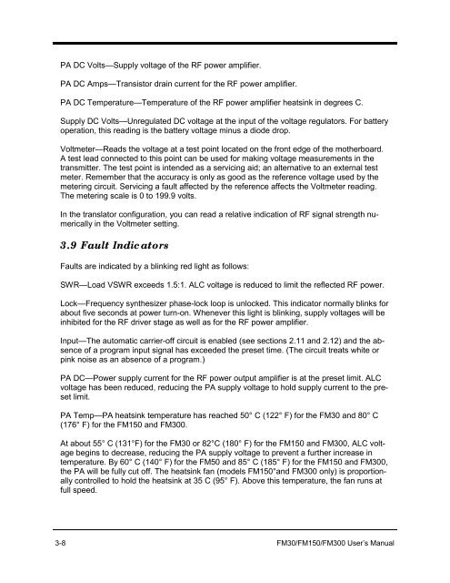
PA DC Volts—Supply voltage of the RF power amplifier.PA DC Amps—Transistor drain current for the RF power amplifier.PA DC Temperature—Temperature of the RF power amplifier heatsink in degrees C.Supply DC Volts—Unregulated DC voltage at the input of the voltage regulators. For batteryoperation, this reading is the battery voltage minus a diode drop.Voltmeter—Reads the voltage at a test point located on the front edge of the motherboard.A test lead connected to this point can be used for making voltage measurements in thetransmitter. The test point is intended as a servicing aid; an alternative to an external testmeter. Remember that the accuracy is only as good as the reference voltage used by themetering circuit. Servicing a fault affected by the reference affects the Voltmeter reading.The metering scale is 0 to 199.9 volts.In the translator configuration, you can read a relative indication of RF signal strength numericallyin the Voltmeter setting.3.9 Fault IndicatorsFaults are indicated by a blinking red light as follows:SWR—Load VSWR exceeds 1.5:1. ALC voltage is reduced to limit the reflected RF power.Lock—Frequency synthesizer phase-lock loop is unlocked. This indicator normally blinks forabout five seconds at power turn-on. Whenever this light is blinking, supply voltages will beinhibited for the RF driver stage as well as for the RF power amplifier.Input—The automatic carrier-off circuit is enabled (see sections 2.11 and 2.12) and the absenceof a program input signal has exceeded the preset time. (The circuit treats white orpink noise as an absence of a program.)PA DC—Power supply current for the RF power output amplifier is at the preset limit. ALCvoltage has been reduced, reducing the PA supply voltage to hold supply current to the presetlimit.PA Temp—PA heatsink temperature has reached 50° C (122° F) for the FM30 and 80° C(176° F) for the FM150 and FM300.At about 55° C (131°F) for the FM30 or 82°C (180° F) for the FM150 and FM300, ALC voltagebegins to decrease, reducing the PA supply voltage to prevent a further increase intemperature. By 60° C (140° F) for the FM50 and 85° C (185° F) for the FM150 and FM300,the PA will be fully cut off. The heatsink fan (models FM150°and FM300 only) is proportionallycontrolled to hold the heatsink at 35 C (95° F). Above this temperature, the fan runs atfull speed.3-8 FM30/FM150/FM300 User’s <strong>Manual</strong>


