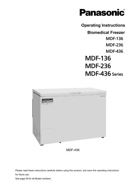
MDF-136 MDF-236 MDF-436 Series - Panasonic Biomedical
MDF-136 MDF-236 MDF-436 Series - Panasonic Biomedical
MDF-136 MDF-236 MDF-436 Series - Panasonic Biomedical
- No tags were found...

You also want an ePaper? Increase the reach of your titles
YUMPU automatically turns print PDFs into web optimized ePapers that Google loves.
INTRODUCTIONRead this operating instructions carefully before using the appliance and follow the instructions forsafety operation.Our company never guarantee any safety if the appliance is used for any objects other than intendeduse or used by any procedures other than those mentioned in this operating instructions.Keep this operating instructions in an adequate place to refer to it as necessary.The contents of the operating instructions will be subjected to change without notice due to theimprovement of performance or functions.Contact our sales representative or agent if any page of the operating instructions is lost or page orderis incorrect.Contact our sales representative or agent if any point in this operating instructions is unclear or if thereare any inaccuracies.No part of this operating instructions may be reproduced in any form without the expressed writtenpermission of our company.CAUTIONOur company guarantees the product under certain warranty conditions. Our company in noway shall be responsible for any loss of content or damage of content.2
PRECAUTIONS FOR SAFE OPERATIONIt is imperative that the user complies with this operating instructionsas it contains important safety advice.Items and procedures are described so that you can use this unit correctly and safely.If the precautions advised are followed, this will prevent possible injury to the user andany other person.Precautions are illustrated in the following way:WARNINGFailure to observe WARNING signs could result in a hazard to personnelpossibly resulting in serious injury or death.CAUTIONFailure to observe CAUTION signs could result in injury to personnel anddamage to the unit and associated property.Symbol shows;this symbol means caution.this symbol means an action is prohibited.this symbol means an instruction must be followed.Be sure to keep this operating instructions in a place accessible to users of this unit.3
PRECAUTIONS FOR SAFE OPERATIONWARNINGDo not use the unit outdoors. Current leakage or electric shock may result if the unit is exposed torain water.Only qualified engineers or service personnel should install the unit. The installation byunqualified personnel may cause electric shock or fire.Install the unit on a sturdy floor and take an adequate precaution to prevent the unit fromturning over. If the floor is not strong enough or the installation site is not adequate, this may resultin injury from the unit falling or tipping over.Never install the unit in a humid place or a place where it is likely to be splashed by water.Deterioration of the insulation may result which could cause current leakage or electric shock.Never install the unit in a flammable or volatile location. This may cause explosion or fire.Never install the unit where acid or corrosive gases are present as current leakage or electricshock may result due to corrosion.Always ground (earth) the unit to prevent electric shock. If the power supply outlet is notgrounded, it will be necessary to install a ground by qualified engineers.Never ground the unit through a gas pipe, water main, telephone line or lightning rod. Suchgrounding may cause electric shock in the case of an incomplete circuit.Connect the unit to a power source as indicated on the rating label attached to the unit. Use ofany other voltage or frequency other than that on the rating label may cause fire or electric shock.Never store volatile or flammable substances in this unit if the container cannot be sealed. Thesemay cause explosion or fire.Do not insert metal objects such as a pin or a wire into any vent, gap or any outlet on the unit.This may cause electric shock or injury by accidental contact with moving parts.Use this unit in safe area when treating the poison, harmful or radiate articles. Improper usemay cause bad effect on your health or environment.Turn off the power switch (if provided) and disconnect the power supply to the unit prior to anyrepair or maintenance of the unit in order to prevent electric shock or injury.Do not touch any electrical parts (such as power supply plug) or operate switches with a wethand. This may cause electric shock.4
PRECAUTIONS FOR SAFE OPERATIONWARNINGEnsure you do not inhale or consume medication or aerosols from around the unit at the time ofmaintenance. These may be harmful to your health.Never splash water directly onto the unit as this may cause electric shock or short circuit.Never put containers with liquid on the unit as this may cause electric shock or short circuit whenthe liquid is spilled.Never bind, process, or step on the power supply cord, or never damage or break the powersupply plug. A broken supply cord or plug may cause fire or electric shock.Do not use the supply cord if its plug is loose. Such supply cord may cause fire or electric shock.Never disassemble, repair, or modify the unit yourself. Any such work carried out by anunauthorized person may result in fire, or electric shock or injury due to a malfunction.Disconnect the power supply plug if there is something wrong with the unit. Continuedabnormal operation may cause electric shock or fire.When removing the plug from the power supply outlet, grip the power supply plug, not the cord.Pulling the cord may result in electric shock or fire by short circuit.Disconnect the power supply plug before moving the unit. Take care not to damage the powercord. A damaged cord may cause electric shock or fire.Disconnect the power plug when the unit is not used for long periods. Keeping the connectionmay cause electric shock, current leakage, or fire due to the deterioration of insulation.If the unit is to be stored unused in an unsupervised area for an extended period, ensure thatchildren do not have access and that door cannot be closed completely.The disposal of the unit should be accomplished by appropriate personnel. Remove door toprevent accidents such as suffocation.Do not put the packing plastic bag within reach of children as suffocation may result.5
PRECAUTIONS FOR SAFE OPERATIONCAUTIONUse a dedicated power source (a dedicated circuit with a breaker) as indicated on the rating labelattached to the unit. A branched circuit may cause fire resulting from abnormal heating.Connect the power supply plug to the power source firmly after removing the dust on the plug.A dusty plug or improper insertion may cause a heat or ignition.Never store corrosive substances such as acid or alkali in this unit if the container cannot besealed. These may cause corrosion of inner components or electric parts.Check the setting when starting up of operation after power failure or turning off of powerswitch. The stored items may be damaged due to the change of setting.Be careful not to tip over the unit during movement to prevent damage or injury.Prepare a safety check sheet when you request any repair or maintenance for the safety of servicepersonnel.6
ENVIRONMENTAL CONDITIONSThis equipment is designed to be safe at least under the following conditions (based on the IEC 61010-1):Indoor use;Altitude up to 2000 m;Ambient temperature 5 o C to 40 o C;Maximum relative humidity 80% for temperature up to 31 o C decreasing linearly to 50% relative humidityat 40 o C;Mains supply voltage fluctuations up to ±10% of the nominal voltage;Transient overvoltages up to the levels of OVERVOLTAGE CATEGORY II;Temporary OVERVOLTAGES occurring on the mains supply;Applicable pollution degree of the intended environment (POLUTION DEGREE 2 in most cases);7
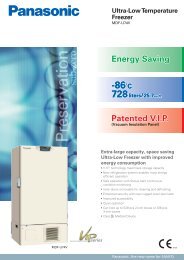
FREEZER COMPONENTS123948765<strong>MDF</strong>-<strong>236</strong>10121113148
FREEZER COMPONENTS1. Door: To open the door, grip the handle.2. Handle: Always grip this handle to open and close the door.3. Lock: Turn counterclockwise to 180 o with a key and the door is securely locked.4. Access port: This is used for leading the measuring cable from the chamber to the outside.5. Drain port: The water accumulated on the bottom of the chamber can be drained through this port.6. Caster: 4 casters are provided to facilitate moving of the cabinet. At the time of installation, makesure that the front 2 casters are not contact with the floor, by adjusting the leveling feet.7. Leveling foot: 2 feet are provided on the front side (right and left). Keep the unit in level byadjusting these feet at the installation.8. Space for temperature recorder: A temperature recorder (optional part) can be attached here. Seepage 26 “Temperature recorder (OPTION)”.9. Control panel: To display the temperature setting and running condition. See page 10 for thedetails.10. Door gasket: This provides a tight door seal and prevents cold air leak. Keep clean.11. Basket: Used for storing the materials in the chamber.12. Remote alarm terminal (on back side): This is used to notice an alarm condition of the unit toremote location. Refer to page 13 “Remote alarm terminal”.13. Battery switch: This is a switch for power failure. Always set the switch in ON position. Be sureto turn off this switch to save the battery if the freezer is not in operating for the long period (more than 1month).14. Power switch: This is for turning ON/OFF the power to the unit. ON – “I” OFF – “○”. This hasa function as an over-current protection breaker (15 A).9
FREEZER COMPONENTSControl panel1 28 7 6 5 4 31. Alarm lamp (ALARM): This lamp will flash when the unit is in alarm condition.2. Digital temperature indicator: This indicator shows the current chamber temperature or settemperature.3. Numerical value shift key ( ): Pressing this key in the setting mode causes the numerical value toshift. ON-OFF of key lock can be selected by pressing this key in the key lock mode.4. Digit shift key ( ): Pressing this key in the setting mode causes the changeable digit to shift. Keylock mode is led by pressing this key for more than 5 seconds in the temperature display mode.5. Set key (SET): Temperature setting mode is led by pressing this key. Once the key is pressed, thechangeable digit is flashed. Pressing this key again after setting desired temperature, the setting isstored into computer memory. If there is no key operation for 90 seconds during the temperature settingmode, the temperature setting mode is invalid automatically. See page 14 for the details.6. Defrost key (DEF): By pressing this key for 5 seconds, the refrigerating operation is stopped.Pressing this key again after defrosting leads resumption of the operation.Note: The refrigerating operation never resume automatically after defrosting.7. Alarm buzzer stop key (BUZZER): Buzzer stop key. Should a further abnormality occur, the buzzerwill sound automatically.8. Alarm test key (ALARM TEST): Test key for alarm device. By pressing this key, the alarm lamp isflashed, remote alarm is activated and buzzer sounds. This means all alarm function operate correctly.This key is available only during normal running.10
INSTALLATION SITETo operate this unit properly and to obtain maximum performance, install the unit in a location with thefollowing conditions:A location not subjected to direct sunlightDo not install the unit under direct sunlight. Installation in a location subjected to direct sunlight cannotobtain the intended performance.A location with adequate ventilationLeave at least 10 cm around the unit for ventilation. Poor ventilation will result in a reduction of theperformance and consequently the failure.A location away from heat generating sourcesAvoid installing the unit near heat-emitting appliances such as a heater or a boiler etc. Heat candecrease the intended performance of the unit.A location with little temperature changeInstall the unit under stable ambient temperature. The allowable ambient temperature is between -5 and+35 o C.A location with a sturdy and level floorAlways install the unit on a sturdy and level floor. The uneven floor or tilted installation may cause failureor injury. Install the unit in stable condition to avoid the vibration or noise. Unstable condition maycause vibration or noise.WARNINGInstall the unit on a sturdy floor. If the floor is not strong enough or the installation site is not adequate,this may result in injury from the unit falling or tipping over.Select a level and sturdy floor for installation. This precaution will prevent the unit from tipping.Improper installation may result in water spillage or injury from the unit tipping over.A location not prone to high humidityInstall the unit in the ambient of 80% R.H. or less humidity. Installation under high humidity may causecurrent leakage or electric shock.WARNINGDo not use the unit outdoors. Current leakage or electric shock may result if the unit is exposed to rainwater.Never install the unit in a humid place or a place where it is likely to be splashed by water.Deterioration of the insulation may result which could cause current leakage or electric shock.A location without flammable or corrosive gasNever install the unit in a flammable or volatile location. This may cause explosion or fire or may result inthe current leakage or electric shock by the corrosion of the electrical components.A location without the possibility of anything fallAvoid installing the unit in the location where anything can fall down onto the unit. This may cause thebreakdown or failure of the unit.11
INSTALLATION1. Removing the packaging materials and tapesRemove all transportation packaging materials and tapes. Open the door and ventilate the unit. If theoutside panels are dirty, clean them with a diluted neutral dishwashing detergent. (Undiluted detergentcan damage the plastic components. For the dilution, refer to the instruction of the detergent.) After thecleaning with the diluted detergent, always wipe it off with a wet cloth. Then wipe off the panels with a drycloth.Note:Remove the cable tie for banding the power supply cord.Prolonged banding may cause the corrosion of the cordcoating2. Adjust the leveling footExtend the leveling feet by rotating them counterclockwiseto contact them to the floor.Ensure the unit is level.Leveling foot4. Ground (earth)The ground (earth) is for preventing the electric shock in the case of the electrical insulation is somehowdegraded. Always ground the unit at the time of installation.WARNINGUse a power supply outlet with ground (earth) to prevent electric shock. If the power supply outlet isnot grounded, it is necessary to install a ground by qualified engineers.Never ground the unit through a gas pipe, water main, telephone line or lightning rod. Suchgrounding may cause electric shock in the case of an incomplete circuit.12
START-UP OF UNITFollow the procedures for the initial and consequent operations of the unit.1. Turn the power switch ON with the chamber empty.2. Turn ON the battery switch.3. Set the chamber temperature to a desired value.4. Allow the unit to achieve the desired chamber temperature.5. Check that the alarm lamp is flashed and the buzzer is activated by pressing alarm test key (ALARMTEST). The remote alarm is also operated. E09 is displayed on the control panel if the battery switch isOFF.6. Now you can put articles into the chamber gradually to minimize the temperature rise.Note:When starting the operation of the freezer for the first time, the alarm lamp (ALARM) blinks after the startof operation. When the chamber temperature reaches around the set temperature, then the alarm lampgoes out (The remote alarm is not activated).If the buttery switch is turned ON before turning ON the power of the freezer, the power failure alarm isactivated and the buzzer sounds and the remote alarm is also activated after the start of operation.Check that the battery switch is OFF before turning ON the freezer.Operation after power failureThe set value is memorized by nonvolatile memory. Accordingly, the freezer resumes the operation withsetting before power failure.When the freezer is recovered from power failure with the chamber temperature higher than the presettemperature, then the high temperature alarm is activated and the buzzer sounds and the remote alarm isalso activated.REMOTE ALARM TERMINALWARNINGAlways disconnect the power supply cord before connecting an alarm device to the remote alarmterminal.The terminal of the remote alarm is installed at the backof the unit. The alarm is outputted from this terminal.Contact capacity is DC 30 V, 2 A.Contact output: At normal condition “Open”At abnormal condition “Close”Note:The remote alarm is stopped by pressing the alarmbuzzer stop key (BUZZER) as the remote alarm isoperated in conjunction with the buzzer except for thepower failure alarm and alarm test.The contact is closed in the case of power failure.Terminal13
CHAMBER TEMPERATURE SETTINGTable 1 shows the basic procedure for setting the chamber temperature. Perform key operations in thesequence indicated in the table. The example in the table is based on the assumption that the desiredtemperature is -35 o C.Note: The unit is set at the factory that the set temperature is -30 o C.Table 1. Basic operation sequence (Example: Chamber temperature -35 o C)Description of operation Key operated Indication after operation1 Switch on the freezer. ----The current chamber temperature isdisplayed.2 Press set key. SET The second digit is flashed3 Press digit shift key.4Press numerical value shift key andscroll the figure to 5.When pressed, the settabledigit moves.When pressed, the figure of settabledigit changes.5 Press set key. SETSet temperature is memorized and thecurrent chamber temperature isdisplayed.Note:• The temperature set mode returns to the temperature display mode automatically when 90 seconds haspassed without any key operation.Although the value of the chamber temperature setting can range between -18 o C and -40 o C, theguaranteed temperature without load is -35 o C at ambient temperature of 35 o C.Key lock functionThis unit is provided with the key lock function. When the key lock is ON, change of temperature settingthrough the key pad is not available. The key lock is set in OFF at the factory.Display Mode FunctionKey lock is OFFEnable to change of temperature settingKey lock is ONDisable to change of temperature settingTable 2. Procedure for key lock setting (change from key lock OFF to key lock ON)Description of operation Key operated Indication after operation1---- The current chamber temperature isdisplayed.2 Press digit shift key for 5 seconds. The first digit is flashed.3Press numerical value shift key andscroll the figure to 1.When pressed, the figure of settabledigit changes.4 Press set key. SETThe key lock is set to ON.The current chamber temperature isdisplayed.• The key lock set mode returns to the temperature display mode automatically when 90 seconds haspassed without any key operation.14
ALARM TEMPERATURE SETTINGThis unit is provided with both high and low temperature alarms. The temperature at which the alarm isactivated will be changed.The available set range for high temperature alarm is between +5 o C and +15 o C, and -5 o C and -15 o C forlow temperature alarm against the set temperature.Note: The temperature alarm is set at ±10 o C of the set temperature at the factory.Display Mode FunctionHigh temperature alarm set See Table 3 on page 15Low temperature alarm set See Table 4 on page 15As an example, Table 3 shows the procedure to set the high temperature alarm so that the alarm canactivate when the chamber temperature is 5 o C higher than the set temperature.Table 4 shows the procedure to set the low temperature alarm so that the alarm can activate when thechamber temperature is 5 o C lower than the set temperature.Table 3. Procedure for setting high temperature alarmDescription of operation Key operated Indication after operation123Press numerical value shift key for5 seconds.Press numerical value shift key andscroll the figure to 1.---- The current chamber temperature isdisplayed.The first digit is flashed.When pressed, the figure of settabledigit changes.4 Press set key. SET The first digit is flashed.Set the temperature to 005 with the5 digit shift key and numerical valueshift key.6 Press set key. SETWhen pressed, the figure of settabledigit changes.When pressed, the figure of settabledigit changes.Alarm temperature is memorized andthe current chamber temperature isdisplayed.Table 4. Procedure for setting low temperature alarmDescription of operation Key operated Indication after operation123Press numerical value shift key for5 seconds.Press numerical value shift key andscroll the figure to 2.4 Press set key. SET5Set the temperature to -05 with thedigit shift key and numerical valueshift key.---- The current chamber temperature isdisplayed.The first digit is flashed.When pressed, the figure of settabledigit changes.The first digit is flashed.Pressing the key shifts the digit which can be set.When pressed, the figure of settabledigit changes.6 Press set key. SETAlarm temperature is memorized andthe current chamber temperature isdisplayed.• The alarm temperature set mode returns to the temperature display mode automatically when 90seconds has passed without any key operation.15
SETTING OF ALARM RESUME TIMEThe alarm buzzer and remote alarm are stopped by pressing alarm buzzer stop key (BUZZER) on thecontrol panel during alarm condition. The alarm buzzer and remote alarm will be activated again aftercertain suspension if the alarm condition is continued. The suspension time can be set by following theprocedure shown in the Table 5 below.The example in the table is based on the assumption that the desired duration is 20 minutes.Note: The duration is set in 30 minutes at the factory.Table 5. Setting procedure for alarm resuming time (change from 30 minutes to 20 minutes)Description of operation Key operated Indication after operation1 ----2Press numerical value shift key for5 seconds.The current chamber temperature isdisplayed.The first digit is flashed.3Set the figure to F25 with thedigit shift key and numerical valueshift key.4 Press set key. SET5Set the figure to 020 with thenumerical value shift key.6 Press set key. SETPressing the key shifts the digit which can be set.When pressed, the figure of settabledigit changes.The current resume time is displayed.The second digit is flashed.When pressed, the figure of settabledigit changes.Alarm resume time is memorized andthe current chamber temperature isdisplayed.• The settable alarm resume time are 10, 20, 30, 40, 50, or 60 minutes. The buzzer and remote alarmwould not resume if the resume time is set in 000.• The setting of alarm resume time cannot be changed during the defrosting.• The buzzer and alarm lamp during power failure or alarm testing cannot be stopped.• The alarm resume time set mode returns to the temperature display mode automatically when 90seconds has passed without any key operation.16
ALARMS & SAFETY FUNCTIONSThis unit has the alarms and safety functions shown in Table 6, and also self diagnostic functions.Table 6. Alarms and safety functionsAlarm & Safety Situation Indication Buzzer Safety operationIf the chamber temperature is higher Alarm lamp is flashed.High temperatureIntermittent tone with Remote alarm with 15than the temperature at which the Digital temperaturealarm15 minutes delay. minutes delay.high temperature alarm is activated. indicator is flashed.Low temperaturealarmPower failure alarmThermal sensorabnormalityIf the chamber temperature is lowerthan the temperature at which thelow temperature alarm is activated.In the case of power failure.When power switch is turned OFF.When the power to the unit isdisconnected.When there is no key pressing ineach setting mode for 90 seconds.Alarm lamp is flashed.Digital temperatureindicator is flashed.Intermittent tone with15 minutes delay.Remote alarm with 15minutes delay.Alarm lamp is flashed. Intermittent tone Remote alarm.Chamber temperature is----- Finishing of eachAuto-returndisplayed.setting mode.Change of setting isKey lock When the key lock is “ON”. ----- -----disable.Alarm lamp is flashed.Remote alarm.If the thermal sensor is disconnected. E01 and chamber temp. Intermittent toneContinuous running.are displayed alternately.Thermal sensorabnormality(<strong>MDF</strong>-<strong>436</strong> only)If the thermal sensor is short-circuited.If the protective sensor for compressoris disconnected.If the protective sensor for compressoris short-circuited.Alarm lamp is flashed.E02 and chamber temp.are displayed alternately.Alarm lamp is flashed.E03 and chamber temp.are displayed alternately.Alarm lamp is flashed.E04 and chamber temp.are displayed alternately.Intermittent toneIntermittent toneIntermittent toneRemote alarm.Continuous running.Remote alarm.Normal operation.Remote alarm.Normal operation.Battery switch When the battery switch is OFF at thechecktime of alarm test.E09 is flashed. Intermittent tone Remote alarm.In the case of failure of compressorcooling fan motor.Compressor temp.abnormality(<strong>MDF</strong>-<strong>436</strong> only)In the case of abnormal hightemperature due to the dust on thecondenser.E10 is flashed.Intermittent toneRemote alarm.Compressor stopsrunning.In the case of abnormal high ambienttemperature.Note:• The above power failure alarm is available when the battery switch is ON and the battery is charged.If the battery switch is OFF or the battery is discharged, only the remote alarm is activated.• The power failure alarm can be kept about 12 hours with the battery charged completely. 2-dayoperation of the freezer is needed to charge the battery full.• The chamber temperature is displayed for 5 seconds if the alarm buzzer stop key (BUZZER) isdepressed during the power failure alarm.• The remote alarm is stopped by pressing alarm buzzer stop key (BUZZER) as the remote alarm isoperated in conjunction with the buzzer, except for the power failure alarm.• After power failure, the operation is resumed with the condition before power failure since thetemperature setting and alarm temperature setting are memorized in a nonvolatile memory.• The battery for power failure alarm is an article for consumption. It is recommended that the batterywill be replaced about every 3 years. Contact our sales representative or agent at the time ofreplacement of the battery.17
ROUTINE MAINTENANCEWARNINGAlways disconnect the power supply to the unit prior to any repair or maintenance of the unit inorder to prevent electric shock or injury.Ensure you do not inhale or consume medication or aerosols from around the unit at the time ofmaintenance. These may be harmful to your health.Cleaning of cabinet• Clean the unit once a month. Regular cleaning keeps the unit looking new.• Use a dry cloth to wipe off small amounts of dirt on the outside and inside of the unit and all accessories.If the outside panels are dirty, clean them with a diluted neutral dishwashing detergent. (Undiluteddetergent can damage the plastic components. For the dilution, refer to the instruction of the detergent.)After the cleaning with the diluted detergent, always wipe it off with a wet cloth. Then wipe off the cabinetor accessories with a dry cloth.• Never pour water onto or into the unit. Doing so can damage the electric insulation and cause failure.• The compressor and other mechanical parts are completely sealed. This unit requires absolutely nolubrication.DefrostingThis freezer is direct-cooling type and the frost is built on the chamber wall during long term operation.The excessive frost possibly make some gap between the cabinet and door gasket, which may causepoor cooling. Remove the frost inside the chamber once a month. Following shows the procedure forremoving the chamber frost.1. Temporarily move all the contents of chamber to another freezer.2. Press the defrost key (DEF) for 5 seconds to stop the refrigerating operation. While the refrigeratingoperation is stopped, the current chamber temperature and dF is displayed on the control panelalternatively.3. Open the door. Leave the freezer as it is.4. Remove the cap of drain port on the bottom of the chamber and drain the accumulated water.5. Wipe up the water remaining in the chamber and then replace the cap of drain port.6. Press the defrost key (DEF) so that the refrigerating operation can be started.7. Once the chamber temperature has dropped to the desired temperature, place the original contentsback in the freezer chamber.Note:After the defrosting, the refrigerating operation is never resumed automatically. Make sure to press thedefrost key (DEF) to start the freezer operation after defrosting.While the freezer stops refrigerating operation for defrosting, neither high temperature alarm nor lowtemperature alarm is effective.18
TROUBLE SHOOTINGMalfunctionThe chamber is not cooledat allThe cooling is poorWhen the unit does notaccept changes of setuptemperatureNoiseCheck/RemedyThe circuit breaker of power source is active.The voltage is too low. (In this case, call an electrician.)The power switch is not ON.The large amount of articles (load) is stored in the chamber atone time.The freezer is in defrost condition.The ambient temperature is too high.The door is not closed firmly.The large amount of frost is built on the chamber wall.The set temperature is not inputted properly.The freezer is in the direct sunlight.There is any heating source near the freezer.A rubber cap and insulation for the access port are not setcorrectly.You put too many unfrozen articles into the freezer compartment.The key lock is set in ON mode.The freezer is not installed on the sturdy floor.The freezer is not leveled with the leveling feet.There is anything touching the frame.The freezer is in the status immediately after start up.The unit sometimes causes a noise when the chamber temperatureis high due to the large load. The noise gets less and lessaccompanying with the cooling of the chamber.Note:If the malfunction is not eliminated after checking the above items, or the malfunction is not shown in theabove table, contact our sales representative or agent.19
DISPOSAL OF UNITWARNINGIf the unit is to be stored unused in an unsupervised area for an extended period ensure that children donot have access and door cannot be closed completely.The disposal of the unit should be accomplished by appropriate personnel. Always remove doorto prevent accidents such as suffocation.Recycle of batteryThe unit contains a rechargeable battery. The battery is recyclable. At the endof it’s useful life, check with you local solid officials option or proper disposal.廢 電 池請 回 收*Label indication is obliged to comply with Taiwanese battery regulation.Decontamination of unitBefore disposing a biomedical freezer with biohazardous danger, decontaminate the biomedical freezer tothe extent possible by the user.20
DISPOSAL OF UNIT(English)FOR EU USERSThe symbol mark and recycling systems described below apply to EU countries and do not apply tocountries in other areas of the world.Your PANASONIC product is designed and manufactured with high quality materials and componentswhich can be recycled and/or reused.The symbol mark means that electrical and electronic equipment, batteries and accumulators, at theirend-of-life, should be disposed of separately from your household waste.Note:If a chemical symbol is printed beneath the symbol mark, this chemical symbol means that the battery oraccumulator contains a heavy metal at a certain concentration. This will be indicated as follows: Hg:mercury, Cd: cadmium, Pb: leadIn the European Union there are separate collection systems for used electrical and electronic equipment,batteries and accumulators.Please, dispose of them correctly at your local community waste collection/recycling centre.Please, help us to conserve the environment we live in!(German)Für EU-StaatenDas Symbol und das erwähnte Wiederverwertungssystem gelten nur für die Länder der EU und nicht fürandere Länder oder Gebiete in der Welt.Die Produkte von PANASONIC werden aus hochwertigen Materialien und Komponenten gefertigt, die sichwieder verwenden lassen.Das Symbol bedeutet, dass elektrische oder elektronische Geräte, Batterien und Akkus am Ende ihrerLebensdauer nicht im Haushaltmüll entsorgt werden dürfen.Hinweis:Ein chemisches Zeichen unter dem Symbol bedeutet, dass die Batterie bzw. der Akku Schwermetalle ingewissen Konzentrationen enthält. Die Metalle werden wie folgt bezeichnet: Hg: Quecksilber, Cd:Kadmium, Pb: BleiIn der Europäischen Union gibt es separate Sammelstellen für elektrische und elektronische Geräte,Batterien und Akkus.Entsorgen Sie solche Geräte bitte richtig in der kommunalen Sammelstelle bzw. im Recyclingzentrum.Helfen Sie mit, die Umwelt in der wir leben, zu schützen.21
DISPOSAL OF UNIT(French)POUR LES UTILISATEURS DE UELe symbole et les systèmes de recyclage évoqués ci-dessous s'appliquent uniquement aux pays de UE.Votre produit PANASONIC est conçu et fabriqué avec des composants et des matériaux de hautesqualités qui peuvent être recyclés et/ou réutilisés.Le symbole signifie que les équipements électriques et électroniques, les batteries et les accumulateursne doivent pas être mis au rebut avec les déchets domestiques à l'issue de leur durée de vie.Remarque:Si un symbole chimique est imprimé sous le symbole, le symbole chimique indique que la batterie oul'accumulateur contient une certaine concentration de métaux lourds. Les métaux sont indiqués de lamanière suivante: Hg: mercure, Cd: cadmium, Pb: plomb.Il existe différents systèmes de collecte pour les équipements électriques et électroniques, les batteries etles accumulateurs usagés au sein de l'Union européenne.Veuillez mettre les équipements au rebut de manière correcte, auprès de votre centre de recyclage/decollecte des déchets local.Aidez-nous à préserver l'environnement dans lequel nous vivons!Les machines ou appareils électriques et électroniques contiennent fréquemment des matières qui, sielles sont traitées ou éliminées de manière inappropriée, peuvent s’avérer potentiellement dangereusespour la santé humaine et pour l’environnement.Cependant, ces matières sont nécessaires au bon fonctionnement de votre appareil ou de votre machine.Pour cette raison, il vous est demandé de ne pas vous débarrasser de votre appareil ou machine usagéavec vos ordures ménagères.(Spanish)PARA USUARIOS DE LA UNION EUROPEAEl símbolo y los sistemas de reciclado descriptos a continuación se aplican para países de la UniónEuropea y no se aplica para países en otras áreas del mundo.Su producto PANASONIC fue diseñado y fabricado con materiales de alta calidad y componentes quepueden ser reciclados y/o vueltos a usar.El símbolo significa que los equipos eléctricos y electrónicos, baterías y acumuladores, al final de su vidaútil, debe ser desechados separadamente de sus residuos domiciliarios.Nota:Si hay un símbolo químico impreso debajo del símbolo, este símbolo químico significa que la batería oacumulador contiene una cierta concentración de un metal pesado. Esto es indicado de la siguientemanera: Hg: mercurio, Cd: cadmio, Pb: plomoEn la Unión Europea hay sistemas de recolección separados para equipos eléctricos y electrónicos,baterías y acumuladores usados.Por favor, disponga de ellos correctamente en el centro de recolección de residuos/reciclado de lacomunidad de su localidad.Por favor, ayúdenos a proteger el medio ambiente en que vivimos!22
DISPOSAL OF UNIT(Portuguese)PARA UTILIZADORES DA UEO símbolo e os sistemas de reciclagem descritos abaixo aplicam-se aos países da UE e não se aplicamaos países noutras áreas do mundo.O seu produto PANASONIC foi concebido e fabricado com materiais e componentes de elevadaqualidade que podem ser reciclados e/ou reutilizados.O símbolo significa que o equipamento eléctrico e electrónico, baterias e acumuladores, em final de vida,não devem ser deitados fora juntamente com o lixo doméstico.Atenção:Se estiver impresso um símbolo químico debaixo do símbolo de , este símbolo químico significa que abateria ou acumulador contém um metal pesado numa determinada concentração. Estará indicado daseguinte forma: Hg: mercúrio, Cd: cádmio, Pb: chumboNa União Europeia existem sistemas de recolha separados para equipamento eléctrico e electrónico,baterias e acumuladores.Por favor, entregue-os no seu centro de reciclagem/recolha de lixo local.Por favor, ajude-nos a conservar o ambiente!(Italian)PER UTENTI UEIl simbolo e i sistemi di riciclaggio descritti di seguito si applicano esclusivamente ai paesi dell’UE.Questo prodotto PANASONIC è stato progettato e realizzato con materiali e componenti di elevata qualitàche possono essere riciclati e/o riutilizzati.Il simbolo di riciclaggio mostrato di seguito indica che i dispositivi elettrici ed elettronici, le batterie e gliaccumulatori, una volta esauriti, devono essere smaltiti separatamente rispetto ai rifiuti domestici.Nota:Se sotto il simbolo di riciclaggio appare un simbolo chimico, esso sta ad indicare che la batteria ol’accumulatore contengono metalli pesanti a determinate concentrazioni. Questo viene specificato comesegue: Hg: mercurio, Cd: cadmio, Pb: piombo.Nell’Unione europea esistono diversi sistemi per la raccolta dei rifiuti speciali quali i dispositivi elettrici edelettronici, le batterie e gli accumulatori.Si raccomanda di provvedere allo smaltimento di tali rifiuti secondo quanto previsto dalle normative vigentiin materia.Aiutaci a conservare l’ambiente!23
DISPOSAL OF UNIT(Dutch)VOOR GEBRUIKERS IN DE EUHet symbool en de recycleersystemen die hieronder beschreven worden, zijn van toepassing op delanden in de EU en zijn niet van toepassing op landen in andere delen van de wereld.Uw PANASONIC product is ontworpen en gemaakt met materialen en onderdelen van hoge kwaliteit, diegerecycleerd en opnieuw gebruikt kunnen worden.Het symbool betekent dat elektrische en elektronische apparatuur, batterijen en accu's aan het eind vanhun leven apart van uw huisafval weggegooid moeten worden.Let op:Indien een chemisch symbool afgedrukt staat onder het symbool, betekent dit chemisch symbool dat debatterij of accu een zwaar metaal met een bepaalde concentratie bevat. Dit wordt als volgt aangegeven:Hg: kwik, Cd: cadmium, Pb: loodIn de Europese Unie zijn afzonderlijke inzamelingssystemen voor gebruikte elektrische en elektronischeapparatuur, batterijen en accu's.Wilt u deze op de juiste manier weggooien bij uw plaatselijk afvalinzameling-/recyclingcentrum in uwbuurt?Help ons het milieu waarin wij leven in stand te houden!(Swedish)FÖR ANVÄNDARE INOM EUDen symbolmärkning och de återvinningssystem som beskrivs här nedan gäller länder inom EU och gällerinte länder i någon annan del av världen.Din PANASONIC-produkt har konstruerats och tillverkats med delar och material av hög kvalitet, som kanåtervinnas och/eller återanvändas.Symbolmärkningen innebär att elektrisk och elektronisk utrustning, batterier och ackumulatorer, vid slutetav deras livslängd, inte får slängas som hushållsavfall utan skall slängas separat.Observera:Om en kemisk symbol finns tryckt under denna symbolmärkning, betyder denna kemiska symbol attbatteriet eller ackumulatorn innehåller en tungmetall med en viss koncentration. Detta indikeras påföljande sätt: Hg: kvicksilver, Cd: kadmium, Pb: blyI den Europeiska Unionen finns det separata uppsamlingssystem för använd elektrisk och elektroniskutrustning, batterier och ackumulatorer.Gör dig av med sådana saker på rätt sätt på den speciella lokala platsen för återsamling/återanvändning.Hjälp oss att bevara den miljö vi lever i!24
DISPOSAL OF BATTERYLocation of a nickel-metal-hydride batteryThis unit is provided a nickel-metal-hydride battery for the power failure alarm. The battery is located inthe electrical box at the back of the product. (Fig. 1)The high voltage components are enclosed in the electrical box. The cover should be removedby a qualified engineer or a service personnel only to prevent the electric shock.Disposal of nickel-metal-hydride battery1. Turn off the power switch and disconnect the power supply plug.2. As shown in the Fig. 2, remove 6 fixing screws on the electrical box and remove the electrical boxcover.3. Remove 2 screws for mounting plate fixing the battery. (Fig. 3)4. Disconnect the battery connector.5. Take out the battery. (Fig. 4)Handling of batteryCover the battery terminal with an insulating tape to avoid the short circuit. Then follow the procedure forrecycling or proper disposal.Electrical boxFig. 1Fig. 2BatteryMounting plateScrewBattery▼▼Fig. 3Mounting plateFig. 425
TEMPERATURE RECORDER (OPTION)WARNINGAlways disconnect the power supply to the unit prior to attachment of a temperature recorder inorder to prevent electric shock or injury.A temperature recorders is available for this freezer as the optional component. The type of the recorderis MTR-G85A/MTR-G85C. For the attachment, the recorder fixing (<strong>MDF</strong>-S740) is necessary. Consultour sales representative or agent for the temperature recorder installation.Setting of MTR-G85A/MTR-G85CPen armPen lifterChart guidesBackup batteryChart hub coverRecording paperInk penKey lockLatchpaper speed selectorFast feed buttonZero adjustment screwPilot lampPower switchLoading the ink pen:1. Slightly raise the end of the pen lifter and remove from the penlifter stopper. Then rotate clockwise as shown in Fig. 1.2. Remove the ink pen from the bag and remove its cap. The capcan be conveniently kept on the cap holder located at the upper leftcorner.3. Press both sides of the pen arm as indicated by the arrows to openthe head clamp at A and B. (See to Fig. 2 illustration 1)4. Position the ink pen so that the guide pins fit into the guide holeson the pen arm. (See to Fig. 2 illustration 2)5. Press the two sides of the head clamp as indicated by the arrowsto secure the ink pen. (See to Fig. 2 illustration 3) From the sideview, the cartridge should fit perfectly on the arm. Confirm that thepen arm is attached to both sides of the ink pen.6. After loading the ink pen, return the pen lifter to the original position.Confirm that the pen lifter has securely entered the pen lifter stopper.123Fig. 1Ink penInk penPen armFig. 226
TEMPERATURE RECORDER (OPTION)Starting recording and setting the time:Turn the power switch ON. The ink pen will move inwardon the circular recording paper and stop temporarily at the0% position (equivalent to the 40 o C line). Then the ink penwill move to the position which indicates the measuredtemperature. (Fig. 3)Time setting method:Place the recording paper at a position slightly in front of thedesired time (the recording paper is rotated to the left). Setthe time by using the fast feed button to quickly rotate therecording paper.The fast feed button can be used to accurately set the time.Ink penHourTemperature0% positionequivalent to40 o C lineFig. 3When the recording paper speed is set to 32 days:The center of the recording paper is divided into 32 equalsections. The lines extending from these lines serve as the32-day time scale. (Fig. 4)Stopping recording:1. Turn OFF the power switch.2. When recording is stopped for a prescribed period, placethe caps back on the ink pen to prevent the ink fromevaporating.Fig. 4Replacing the recording paper:1. Slightly raise the end of the pen lifter and remove from the pen lifter stopper. Rotate the tip of the penclockwise until it rests on top of the pen lifter.2. Remove the chart hub cover, and then replace the recording paper.3. Place the chart hub cover. Remove and dispose of the piece of paper. Confirm that the new recordingpaper is inside of the chart guides.4. Set the correct time.27
SPECIFICATIONSProduct nameExternal dimensionsInternal dimensions<strong>Biomedical</strong> Freezer<strong>MDF</strong>-<strong>136</strong>W640 mm x D687 mm xH881 mmW525 mm x D440 mm xH715 mm<strong>Biomedical</strong> Freezer<strong>MDF</strong>-<strong>236</strong>W905 mm x D687 mm xH881 mmW790 mm x D440 mm xH715 mm<strong>Biomedical</strong> Freezer<strong>MDF</strong>-<strong>436</strong>W1265 mm x D807 mm xH905 mmW1140 mm x D550 mm xH735 mmEffective capacity 138 L 221 L 426 LExteriorPainted steelInteriorColored aluminum plateDoorPainted steelInsulationRigid polyurethane foamed-in placeBasketsPolyethylene coated steel wireAccess portDiameter 17 mm, Right side and bottom leftCompressor Hermetic type, 175 W Hermetic type, 350 WCondenserFin & tube + wire & tube typeWire and tube typeFan motor 2 WEvaporatorAluminum tube on sheet typeRefrigerantR-404ATemperature controller Electronics controller (between -18 and -40 o C)Temperature display Digital display (between -50 and +50 o C)Temperature sensorThermister sensorTemperature alarmFlash of digital indicator and alarm lamp, Buzzer, (Remote alarm)Accessories1 set of key, 1 Scraper,2 baskets1 set of key, 1 Scraper,3 baskets1 set of key, 1 Scraper,4 basketsWeight 45 kg 54 kg 71 kgBatteryFor power failure alarm, Nickel-metal-hydride battery, DC 6 V, 1100 mAhAutomatic chargeOptional componentTemperature recorder (MTR-G85A, MTR-G85C)Recorder fixing (<strong>MDF</strong>-S740)Storage basketsNote:Design or specifications will be subject to change without notice.Refer to the updated catalog when ordering an optional component.The battery for power failure alarm is an article for consumption. It is recommended that the battery willbe replaced about every three years. Contact our sales representative or agent at the time ofreplacement of the battery for recycling.28
PERFORMANCEProduct nameModel number<strong>MDF</strong>-<strong>136</strong>-PA<strong>MDF</strong>-<strong>136</strong>-PT<strong>Biomedical</strong> Freezer<strong>MDF</strong>-<strong>136</strong><strong>MDF</strong>-<strong>136</strong>-PK<strong>MDF</strong>-<strong>136</strong>-PE<strong>MDF</strong>-<strong>136</strong>-PP<strong>MDF</strong>-<strong>136</strong>-PUCooling performance-35 o C (ambient temperature; 35 o C, no load)Temperature control range-20 o C to -35 o CRated voltage AC 110 V/115V AC 220 V AC 220 V/230 V/240 VRated frequency 60 Hz 50 Hz/60 Hz 50 HzRated power consumption 140 W/140 W 145 W/150 W 145 W/145 W/145 WNoise levelMaximum pressure37 dB [A] (background noise; 20 dB)2.57 MPaProduct nameModel number<strong>MDF</strong>-<strong>236</strong>-PA<strong>MDF</strong>-<strong>236</strong>-PT<strong>Biomedical</strong> Freezer<strong>MDF</strong>-<strong>236</strong><strong>MDF</strong>-<strong>236</strong>-PK<strong>MDF</strong>-<strong>236</strong>-PE<strong>MDF</strong>-<strong>236</strong>-PP<strong>MDF</strong>-<strong>236</strong>-PUCooling performance-35 o C (ambient temperature; 35 o C, no load)Temperature control range-20 o C to -35 o CRated voltage AC 110 V/115V AC 220 V AC 220 V/230 V/240 VRated frequency 60 Hz 50 Hz/60 Hz 50 HzRated power consumption 140 W/140 W 160 W/170 W 160 W/160 W/160 WNoise levelMaximum pressure36 dB [A] (background noise; 20 dB)2.26 MPaProduct nameModel number<strong>MDF</strong>-<strong>436</strong>-PA<strong>MDF</strong>-<strong>436</strong>-PT<strong>Biomedical</strong> Freezer<strong>MDF</strong>-<strong>436</strong><strong>MDF</strong>-<strong>436</strong>-PK<strong>MDF</strong>-<strong>436</strong>-PE<strong>MDF</strong>-<strong>436</strong>-PP<strong>MDF</strong>-<strong>436</strong>-PUCooling performance-35 o C (ambient temperature; 35 o C, no load)Temperature control range-20 o C to -35 o CRated voltage AC 110 V/115V AC 220 V AC 220 V/230 V/240 VRated frequency 60 Hz 50 Hz/60 Hz 50 HzRated power consumption 230 W/230 W 220 W/220 W 220 W/220 W/220 WNoise levelMaximum pressureNote :The unit with CE mark complies with EC directives.40 dB [A] (background noise; 20 dB)2.18 MPa29
CAUTIONPlease fill in this form before servicing.Hand over this form to the service engineer to keep for his and your safety.Safety check sheet1. Freezer contents :Risk of infection:Risk of toxicity:Risk from radioactive sources:□Yes□Yes□Yes□Yes□No□No□No□No(List all potentially hazardous materials that have been stored in this unit.)Notes :2. Contamination of the unitUnit interiorNo contaminationDecontaminatedContaminatedOthers:□Yes□Yes□Yes□Yes□No□No□No□No3. Instructions for safe repair/maintenance of the unita) The unit is safe to work onb) There is some danger (see below)□Yes□Yes□No□NoProcedure to be adhered to in order to reduce safety risk indicated in b) below.Date :Signature :Address, Division :Telephone :Product name :<strong>Biomedical</strong> FreezerProduct :<strong>MDF</strong>-Serial number : Date of Installation :Please decontaminate the unit yourself before calling the service engineer.30
1-1-1 Sakata, Oizumi-Machi, Ora-Gun, Gunma 370-0596 Japan© <strong>Panasonic</strong> Healthcare Co., Ltd. 2012Printed in Japan7FB6P151279001S0412-10412