1955-57 delphi power steering box installation - Eckler's Classic ...
1955-57 delphi power steering box installation - Eckler's Classic ...
1955-57 delphi power steering box installation - Eckler's Classic ...
- No tags were found...

Create successful ePaper yourself
Turn your PDF publications into a flip-book with our unique Google optimized e-Paper software.
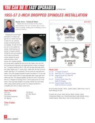
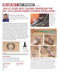
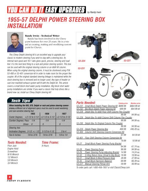
y Randy Irwin<strong>1955</strong>-<strong>57</strong> DELPHI POWER STEERING BOXINSTALLATIONRandy Irwin - Technical Wr i t e rRandy has been involved in the Chevyp a rts business for over 25 years. He is a wizardat creating, making and modifying customp a rts for Chevys.This Chevy Delphi <strong>steering</strong> kit is an excellent way to upgrade yourclassic to modern <strong>steering</strong> if you wish to stay with a <strong>steering</strong> <strong>box</strong>. Itsinternal rack spool and 16:1 ratio gives quick, precise, <strong>steering</strong> and roadfeel. It is the next best thing to a rack and pinion <strong>steering</strong> system. This <strong>box</strong>can be used with the original <strong>steering</strong> column or an ididit tilt column.When using the original <strong>steering</strong> column, it must be shortened using P/N53-400 or 53-401 conversion kit in order to make room for the proper flexcoupler. All of the original standard <strong>steering</strong> linkage is maintained while thestock <strong>steering</strong> <strong>box</strong> is removed and no longer used. Any type of header orcast iron manifold exhaust system will fit with the Delphi kit. This articlecovers a small block short water pump <strong>installation</strong>. Big block short waterpump <strong>installation</strong>s are similar. If you want a classic that truly drives like abrand new car, install our Chevy Delphi <strong>steering</strong> kit!53-22453-23153-227Tech TipsWhen installing the 605, 670, Delphi or rack and pinion <strong>steering</strong> conversi o n s, a different set of alignment specs must be used to avoid wanderingand over-sensitive <strong>steering</strong> feel:<strong>1955</strong> 1956 19<strong>57</strong>Caster Degrees: +2-1/2 to 3-1/2 +2-1/2 to 3-1/2 +2-1/2 to 3-1/2Camber Degrees: Pass- -1/4 -1/4 -1/4Steering AxisTools Needed:Floor JackEngine HoistScrewdriver9/16 Wrench1/2 Wrench5/8 Wrench3/4 WrenchDriver- 0 0 0Inclination Degrees: 3-1/2 +/- 1/2 3-1/2 to 4 1/2 3 to 4Toe-In Inches: 1/8 to 3/16 1/8 to 3/16 1/8 to 1/4Time Frame:8-HoursParts Needed: Catalog price Member price53-231 Small Block Delphi Power Steering Kit $699.99 $664.99 kit53-232 Big Block Delphi Power Steering Kit 699.99 664.99 kit53-228 Delphi Box To ididit Floor Shift Column Flex Coupler99.99 94.99 ea.53-229 Delphi Box To ididit Column Shift Column Flex Coupler99.99 94.99 ea.53-230 Delphi Box To Original Column Flex Coupler99.99 94.99 ea.53-224 Delphi Power Steering Box 469.99 446.49 ea.53-400 Column Shift Steering Column Conversion Kit67.99 64.59 kit53-401 Floor Shift Steering Column Conversion Kit19.99 18.99 kit53-27 Small Block Power Steering Pump Bracket64.99 61.74 ea.53-28 Power Steering Pump 99.99 94.99 ea.53-29 Power Steering Pump Adjusting Bracket 14.99 14.24 ea.53-50 O-Ring Return Hose (Small & Big Block) 19.99 18.99 ea.53-51 Small Block O-Ring Pressure Hose 39.99 37.99 ea.18-35 Small Block Harmonic Balancer 69.99 66.49 ea.53-227 Manual Steering Pitman Arm 59.99 56.99 ea.To order parts call 1-800-456-19<strong>57</strong> or visit <strong>Classic</strong>Chevy.com10CHEVY CLA SS I CS
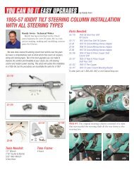
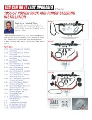
#1a #1bPhoto #1a & 1b: The original <strong>steering</strong> <strong>box</strong> is bolted to theframe with three 3/8” carriage bolts and nuts. The stock mastj a c ket (<strong>steering</strong> column) protrudes through the firewall about3-1/2”. The <strong>steering</strong> shaft that connects the <strong>steering</strong> <strong>box</strong> to the<strong>steering</strong> wheel is part of the <strong>steering</strong> <strong>box</strong> and not removable.53-228 53-229 53-230Photo #4: A flex coupler (rag joint) is used to connect the<strong>steering</strong> <strong>box</strong> to the <strong>steering</strong> column to improve road feel byreducing the transfer of bumps and vibration to the <strong>steering</strong>wheel. Three different couplers are available so the stockcolumn or any aft e rm a r ket column can be used with theDelphi <strong>box</strong>. The bottom of each of the couplers is 17millimeter female to connect to the <strong>steering</strong> <strong>box</strong>. The top ofeach coupler is where the difference is. Follow the chart belowto determine the correct coupler to be used for your part i c u l a ra p p l i c a t i o n .53-228 17mm Delphi <strong>box</strong> to columns with 3/4”-DD shaft53-229 17mm Delphi <strong>box</strong> to columns with 1”-DD shaft53-230 17mm Delphi <strong>box</strong> to columns with 3/4”- spline shaftPhoto #2a & 2b: The new#2aDelphi <strong>power</strong> <strong>steering</strong> <strong>box</strong>has a one piece case and is bolted to the frame using theoriginal three holes in the frame. The input shaft on the Delphi<strong>box</strong> is a male 17 millimeter double-D.#2b #5a #5bPhoto #5a & 5b: The coupler is held to the <strong>steering</strong> <strong>box</strong> shaftand <strong>steering</strong> column shaft with set screws and lock nuts.#3bPhoto #3a & 3b: The Delphi#3a<strong>box</strong> includes new bolts toattach the <strong>box</strong> to the frame. With the <strong>box</strong> bolted to the frame,the clearance between the <strong>box</strong> and the exhaust is the same onthe Delphi <strong>box</strong> and the original one. The Delphi <strong>box</strong> is tallerthan the original <strong>box</strong> at the firewall. If the stock mast jacket isgoing to be used, P/N 53-400 mast jacket conversion forcolumn shift or 53 - 401 for floor shift (refer to CCI web site fora copy of the tech article) will need to be used.#6a #6bPhoto #6a & 6b & 6c: T h eoriginal front motor mountsattach to the front of the engineon each side of the harm o n i cb a l a n c e r. The driver’s sidemount will be replaced with acombination left front motormount and <strong>power</strong> <strong>steering</strong> #6cpump mounting bracket. Thisb r a c ket can also be used as the <strong>power</strong> <strong>steering</strong> pump bracke tonly if the engine is side mounted. Using an engine hoist orfloor jack under the oil pan, slightly raise the engine to take theload off the front engine mounts.11SEPTEMBER 2007
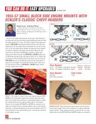
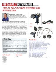
#11a#11b#7a #7bPhoto #7a & 7b: Remove the stock left front motor mount andreplace it with bracket P/N 53-27. The new bracket is held tothe engine block with the supplied grade-5 bolts and lockwashers.Photo #8: With thepump bracket in place,lower the engine downand install the newupper rubber cushion,washer and nut.#11cPhoto #11a & 11b & 11c: T h epump adjusting arm P/N 53-2 9 connects to the upper studon the back of the pump andto the upper water pump bolton the driver’s side of the engine. At the stud on the rear of thepump, a supplied flat washer, lock washer and nut is used. Atthe water pump the stock water pump bolt can be used.Photo #12: The bolt-onc r a n k s h a ft pulley P/N 53-3 4 will drive the <strong>power</strong><strong>steering</strong> pump. If theengine has the stockh a rmonic balancer withthe riveted-on pulley, itwill need to be updatedwith a pulley that acceptsbolt-on pulleys. P/N 18-35 is a 6-1/8” diameter harm o n i cbalancer that will accept bolt-on pulleys.#9a #9bPhoto #9a & 9b: There are two studs on the back of the <strong>power</strong><strong>steering</strong> pump P/N 53-28. The lower stud keys into the rearslot on the <strong>power</strong> <strong>steering</strong> pump bracket. On the front of thepump there are four 3/8” holes. The lower hole is used toattach the pump to the <strong>power</strong> <strong>steering</strong> pump bracke t .#13a #13b#13d#13c#10a #10bPhoto #10a & 10b: Place the pump into the <strong>power</strong> <strong>steering</strong>pump bracket. The rear stud is secured to the bracket with asupplied flat washer, lock washer and nut. The front of thepump is held to the bracket with a supplied 3/4” long bolt andlock washer.Photo #13a & 13b & 13c & 13d& 13e: The crankshaft pulleyfor the <strong>power</strong> <strong>steering</strong> pumpP/N 53-34 is the third groovepulley for the crankshaft. Thispulley is made to fit inside a#13esingle or double groove pulley.The double groove pulley P/N 51-03 has two collars that willkey into the single groove pulley P/N 53-34. With the pulleyskeyed together, they can be bolted to the harmonic balancer.12CHEVY CLA SS I CS
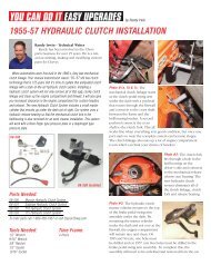
#14a #14bPhoto #14a & 14b: The <strong>power</strong> <strong>steering</strong> pump pulley is held tothe pump with a locking nut. There is a key on the shaft thatlocks the pulley to the pump shaft. Install the <strong>power</strong> <strong>steering</strong>pump pulley P/N 53-30 onto the pump shaft and torque thenut to 45 ft-lbs.Photo #18: T h er e t u rn hose P/N 53-5 0 has a 16millimeter male O-ring fitting on oneend and is straightcut hose at the otherend. The male end ofthe hose connects tothe smaller fitting onthe <strong>steering</strong> <strong>box</strong>. Thehose end connects tothe barbed nipple on the back of the pump using a small hoseclamp. Enjoy your new <strong>power</strong> <strong>steering</strong> <strong>box</strong>! Good luck.#15a #15bPhoto #15a & 15b: Next, install the <strong>power</strong> <strong>steering</strong> belt P/N 41-1 0 . The pump will lean inward leaving enough clearancebetween the pump reservoir and the upper control arm stud.#16a#16bPhoto #16a & 16b: The Delphi <strong>box</strong> uses O-ring fittings. Thistype of fitting does not require any sealer on the threads. Just asmall amount of oil is needed when attaching the hoses to the<strong>steering</strong> <strong>box</strong>.#17a #17bPhoto #17a & 17b: The pressure hose P/N 53-51 has an 18millimeter male O-ring fitting on one end and a 3/8” flare nuton the other end. The male end of the hose connects to thelarger fitting on the <strong>steering</strong> <strong>box</strong>. The flare nut connects to themale fitting on the back of the <strong>power</strong> <strong>steering</strong> pump.13SEPTEMBER 2007