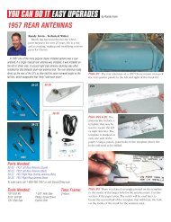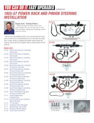
1955-57 power rack and pinion steering - Ecklers Classic Chevy
1955-57 power rack and pinion steering - Ecklers Classic Chevy
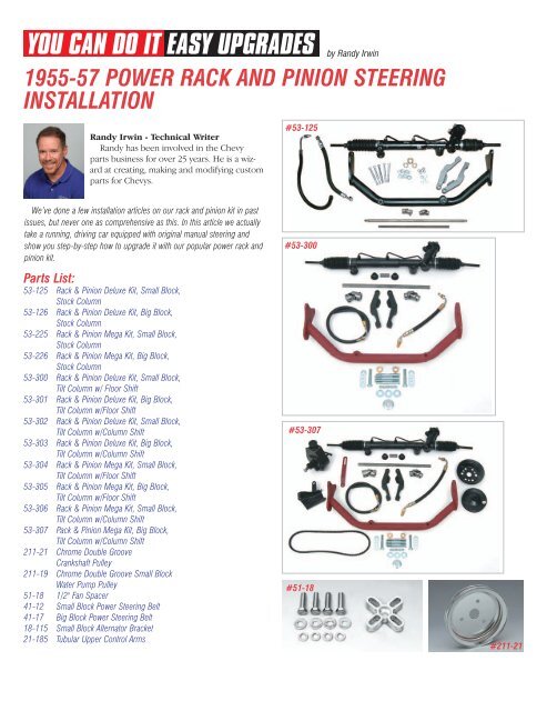
1955-57 power rack and pinion steering - Ecklers Classic Chevy
- No tags were found...

You also want an ePaper? Increase the reach of your titles
YUMPU automatically turns print PDFs into web optimized ePapers that Google loves.
15a15bPhoto 14: The Eckler’s<strong>Classic</strong> <strong>Chevy</strong> Rack <strong>and</strong>Pinion crossmember is sostrong you can use it tojack up the front end! Other<strong>rack</strong> kits on the market usea flimsy lightweightsupport or braces that donot tie the frame railstogether.18a 18b 18cPhotos 18a, 18b & 18c:Now we are ready toconnect the U-joints <strong>and</strong> shaft from the<strong>rack</strong> <strong>and</strong> <strong>pinion</strong> to the <strong>steering</strong> column,but we have a problem. The existing non-CCI headers that are onour project car are right in the way. If we had some side room,we could add the 3rd U-joint support kit P/N 53-317 <strong>and</strong> snakethe shaft around the header tubes, but there is just no room hereto do that. Instead, we will remove the left h<strong>and</strong> header only <strong>and</strong>replace it with the Eckler’s <strong>Classic</strong> <strong>Chevy</strong> 3/4-length left headerP/N 24-53C-LH.19a 19b 19cPhotos 15a & 15b:The <strong>rack</strong> <strong>and</strong><strong>pinion</strong> kit includes new <strong>steering</strong> knuckles (<strong>steering</strong> arms) that are1-5/8" shorter than the original ones. The shorter arms arenecessary to maintain the original <strong>steering</strong> radius.16a16bPhotos 19a, 19b & 19c: The <strong>rack</strong> & <strong>pinion</strong> kit includes two largebrass bushings. One of the two bushings will fit into the bottomof the original mast jacket to support the lower end of the new<strong>steering</strong> shaft. Choose the correct size bushing that will slide upinto the bottom of the mast jacket <strong>and</strong> drive the bushing in sothat it is flush with the bottom of the tube.Photos 16a & 16b: The original <strong>steering</strong> arms are bolted to thespindles with two 7/16" bolts <strong>and</strong> nuts. Remove the two nuts <strong>and</strong>install the new arms.17a17b17cPhotos 17a, 17b & 17c: The Eckler’s<strong>Classic</strong> <strong>Chevy</strong> Rack <strong>and</strong> Pinion Kitutilizes the original outer tie rod ends<strong>and</strong> adjusting sleeves so there are nometric parts installed on your <strong>Classic</strong>!The outer tie rod ends <strong>and</strong> adjustingsleeves were in perfect shape on ourproject car so we will reuse them. If theywere bad, the adjusting sleeves areavailable new as P/N 21-08 <strong>and</strong> theouter tie rod ends P/N 21-07. Install theadjusting sleeves <strong>and</strong> tie rod ends <strong>and</strong>set the toe in as close as you can fornow. Once the <strong>rack</strong> <strong>and</strong> <strong>pinion</strong> iscompletely installed, the car will need tobe taken to the alignment shop.Photo 20: When using an original <strong>steering</strong> column, a new shaft<strong>steering</strong> shaft kit is supplied with the <strong>rack</strong> <strong>and</strong> <strong>pinion</strong> kit. Thisincludes the column shaft, the intermediate shaft <strong>and</strong> upper <strong>and</strong>lower U-joints.21a21bPhotos 21a & 21b: The U-joints are held to the intermediate shaftwith set screws <strong>and</strong> jam nuts. Make sure when the shaft isinstalled in the U-joint that the shaft does not protrude past theinside of the yoke. If it does, the shaft will make contact with theopposing yoke of the U-joint <strong>and</strong> create a bind.
22a 22b 22c26Photos 22a, 22b & 22c: First, install the lower U-joint onto thedouble-D shaft. Once the U-joint has been located on the shaft,tighten the one set screw on the flat of the double-D shaft. Theset screw will leave a mark on the shaft. Next, using a 5/16" drillbit, drill a dimple in the shaft at the mark. The dimple is used asa seat for the set screw.23a23bPhotos 26: Theupper U-joint is thelarger of the two U-joints supplied. Thetop of the U-jointhas 3/4"-36 splinesto match the <strong>steering</strong> column shaft <strong>and</strong> the bottom of the U-jointhas a 3/4" double-D to match the intermediate shaft.27a27bPhotos 23a & 23b: The input shaft on the <strong>rack</strong> <strong>and</strong> <strong>pinion</strong> unithas a coped-out area for the set screw. With the set screw seatedin the coped out area, the input shaft will be flush with the insideU-joint yoke.24a24bPhotos 24a & 24b: Thenew <strong>steering</strong> columnshaft has 3/4" - 36splines at the bottom ofthe shaft <strong>and</strong> the samesplines <strong>and</strong> threads at the top like the original. The same splinesat the top allows you to use the stock <strong>steering</strong> wheel or anyaftermarket <strong>steering</strong> wheel.Photos 27a & 27b: Install the lower U-joint <strong>and</strong> shaft on to the<strong>rack</strong> <strong>and</strong> <strong>pinion</strong> unit making sure the set screw is seated in thecoped out area on the input shaft. Lay the 3/4" double-D shaftnext to the upper U-joint <strong>and</strong> mark the shaft where it will need tobe cut to properly engage the yoke on the joint. The intermediateshaft is long enough to reach the firewall even if a late model tiltcolumn were installed28a28b25Photos 25: Installthe <strong>steering</strong> wheelor <strong>steering</strong> wheeladapter on theshaft <strong>and</strong> slide theshaft down intothe <strong>steering</strong>column. Place apiece ofcardboard orfolded-over paperbetween the uppermast jacket <strong>and</strong><strong>steering</strong> wheel or adapter. You want to achieve a 1/16" or so gapbetween the <strong>steering</strong> wheel hub <strong>and</strong> <strong>steering</strong> column.Photos 28a & 28b: The shaft can be cut with a hack saw, b<strong>and</strong>saw or chop saw. With the intermediate shaft cut, remove theupper U-joint from the <strong>steering</strong> shaft, install the now shortenedintermediate shaft <strong>and</strong> lower U-joint to the <strong>rack</strong> <strong>and</strong> <strong>pinion</strong>,install the upper U-joint the intermediate shaft <strong>and</strong> slide the<strong>steering</strong> shaft into the upper U-joint.Photo 29: With the upper U-joint inplace, tighten the one set screw onthe flat of the 3/4" double-D makinga mark. Remove the intermediateshaft <strong>and</strong> U-joints, remove the upperU-joint <strong>and</strong> drill a dimple in theshaft just like you did for the lowerU-joint for the set screw.
Photo 30: With the U-jointslocated on the intermediateshaft, we gave the shaft <strong>and</strong> U-joints a shot of gloss black paint.35a35b32a32bPhotos 32a & 32b: We have removed the left h<strong>and</strong> header only<strong>and</strong> replaced it with the Eckler’s <strong>Classic</strong> <strong>Chevy</strong> 3/4-length headerP/N 24-53C-LH. This header can be purchased as a pair P/N 24-53 (uncoated) or P/N 24-53C (coated). The #24-53 headers willwork with stock front mounts or any br<strong>and</strong> side mounts,automatic column shift or manual transmissions, with or withoutmechanical clutch linkage <strong>and</strong> with either straight or angle plugheads. With the #24-53 headers there is plenty of room for thelower U-joint <strong>and</strong> shaft on the driver’s side.33a33bPhotos 35a & 35b: Future plans include adding air conditioning,so we will install a double groove pulley along with the thirdt<strong>rack</strong> pulley on the balancer. All three pulleys together measure1-3/4" deep. Using the marks on the fan shroud as the referencepoint, cut a 1-3/4" deep notch in the shroud. A fine tooth hacksaw or tin snips works great to cut the aluminum shroud.36a36bPhotos 36a & 36b: The <strong>power</strong> <strong>steering</strong> pump mounts to the frontof the engine down low on the driver’s side. The pump mountingb<strong>rack</strong>et P/N 53-27 or 53-27C can be used as the <strong>power</strong> <strong>steering</strong>pump mounting b<strong>rack</strong>et on cars with side engine mounts or as acombination front engine mounting b<strong>rack</strong>et <strong>and</strong> pump mountingb<strong>rack</strong>et on engines with front mounts.37a37b33cPhotos 33a, 33b & 33c: The upperbearing in the <strong>steering</strong> column P/N 53-21 was bad so this was the perfect timeto change it before we installed the<strong>steering</strong> shaft, the <strong>steering</strong> wheel adapter<strong>and</strong> the intermediate with U-joints. Witheverything set <strong>and</strong> the screws on the U-joints locked down, we had a 1/16" gap between the <strong>steering</strong>wheel adapter <strong>and</strong> the top of the <strong>steering</strong> column. This gap willkeep the <strong>steering</strong> wheel adapter from touching the paintedsurface of the turn signal housing.Photos 37a & 37b: Thepump b<strong>rack</strong>et P/N 53-27(small block short waterpump) is held to the front of the engine with two 3/8" X 3/4" bolt<strong>and</strong> lock washers provided.38a 38b 38c34a34bPhotos 34a & 34b: A third t<strong>rack</strong> pulley must be added to thecrankshaft to drive the <strong>power</strong> <strong>steering</strong> pump. By adding a thirdt<strong>rack</strong> pulley to the crankshaft, the fan shroud will need to benotched. Mark the shroud <strong>and</strong> remove.Photos 38a, 38b & 38c: The <strong>power</strong> <strong>steering</strong> pump P/N 53-28 isheld to the b<strong>rack</strong>et with a 3/8" X 3/4" bolt <strong>and</strong> lock washer infront <strong>and</strong> a stud at the rear that uses a 3/8" flat washer, lockwasher <strong>and</strong> nut provided with the b<strong>rack</strong>et. With the pump inplace, we now see that the shroud will need to be trimmed for the<strong>power</strong> <strong>steering</strong> pump pulley. This would be true with a big blockor small block engine.
39a39b43a43bPhotos 39a & 39b: Using the <strong>power</strong> <strong>steering</strong> pump pulley P/N53-50 as a pattern, cut a template of the pulley.40a40b43cPhotos 43a, 43b & 43c: Startingslow, trim the shroud with a cutoffwheel or tin snips until thepulley will clear the fan shroudwith the pump adjusted all theway out. This will require the fanshroud to be installed <strong>and</strong>removed several times.44a44bPhotos 40a & 40b: With the <strong>power</strong> <strong>steering</strong> pump reservoirtouching the upper control arm stud, place the cardboard pulleytemplate on the <strong>power</strong> <strong>steering</strong> pump shaft <strong>and</strong> mark the fanshroud at the fan blade opening where it will need to be trimmed.41a 41b 41c44c44dPhotos 41a, 41b & 41c: When the <strong>power</strong> <strong>steering</strong> pump wasinstalled, the shaft made a mark on the shroud. Using the twomarks that were made with the pulley template, center thetemplate on the scratch that the pump shaft made <strong>and</strong> mark theouter circumference of the template. Next, make several smalldiameter marks on the shroud to be used as reference pointswhen trimming the shroud.42a42bPhotos 42a & 42b: First, drill a 1-3/4" hole at the center of themarkings to line up with the <strong>power</strong> <strong>steering</strong> pump shaft when thepump is adjusted as far out as it will go.Photos 44a, 44b, 44c & 44d: With the pump <strong>and</strong> the singlegroove <strong>power</strong> <strong>steering</strong> pump crankshaft pulley P/N 53-34installed, you can see that the fan shroud is in the way of thebelt. Mark the shroud where the fan belt is going to travel <strong>and</strong>once again remove the shroud <strong>and</strong> trim it for the <strong>power</strong> <strong>steering</strong>pump belt.Photo 45: Before we installedthe fan shroud for the last time,we made a template of thecut-outs on the shroud. If yougo to our websitewww.classicchevy.com <strong>and</strong> pullup either P/N 18-306 or P/N 18-307 fan shroud, you c<strong>and</strong>ownload the template. Or if you wish you can send a selfaddressedenvelope attn: CCI Tech Dept Fan Shroud Template<strong>and</strong> we will be glad to send you a copy.
46a46b46cPhoto 50: Now you may install thefan shroud for the last time. The legson the shroud get trapped between thecore support <strong>and</strong> the radiator to finishthings off.46dPhotos 46a, 46b, 46c & 46d: Thefirst groove on our balancerpulleys closest to the harmonicbalancer will drive the waterpump <strong>and</strong> alternator. The secondgroove is for the water pump <strong>and</strong>air conditioning compressor <strong>and</strong>the third groove runs the <strong>power</strong><strong>steering</strong>. The single groove, chrome, <strong>power</strong> <strong>steering</strong> pump pulleyP/N 53-34C fits inside the double groove, chrome pulley P/N211-19. The pulleys are held to the harmonic balancer with three3/8" X 3/4" bolts. Lower the fan shroud down in the enginecompartment <strong>and</strong> lean it back on the engine <strong>and</strong> install thecrankshaft pulleys.51a 51b 51cPhotos 51a, 51b & 51c:The slotted end of thepump adjusting arm P/N 53-29 or 53-29C anchors to the back ofthe <strong>power</strong> <strong>steering</strong> pump with a 3/8" flat washer, lock washer<strong>and</strong> nut. The other end of the adjusting arm attaches to the upperwater pump bolt.52a52b47a47bPhotos 52a & 52b: The pressure hose P/N 53-38 (small block) orP/N 53-74 (big block) has a brass fitting on the end where itattaches to the pump <strong>and</strong> an 18 millimeter male O-ring fittingwhere it attaches to the <strong>rack</strong> <strong>and</strong> <strong>pinion</strong>. The brass fitting screwsinto the female inverted hole in the back of the pump.Photos 47a & 47b: Next, install the water pump <strong>and</strong> water pumppulley. A chrome double groove pulley P/N 211-19 will be used.48a48bPhoto 53: The return hose uses a hoseclamp at the <strong>power</strong> <strong>steering</strong> pump <strong>and</strong>has a 16 millimeter male O-ring fittingwhere it attaches to the <strong>rack</strong> <strong>and</strong> <strong>pinion</strong>.Photos 48a & 48b: A 1/2" fan spacer P/N 51-18 is installedbetween the fan blade <strong>and</strong> water pump pulley so that the tips ofthe fan blade will clear the third t<strong>rack</strong> pulley on the crankshaft.49a 49b 49cPhoto 54: The 18 millimeterpressure port on the <strong>rack</strong> <strong>and</strong> <strong>pinion</strong>is to the left of the input shaft whilethe 16 millimeter return port is tothe right of the input shaft.55a55bPhotos 49a, 49b & 49c:We are going to swap outthe black double groove pulley P/N 53-30 on the <strong>power</strong> <strong>steering</strong>pump for the billet aluminum chrome single groove pulley P/N53-311 for a more custom look. The pulley is keyed to the pumpshaft <strong>and</strong> is held in place with a nut supplied with the pump.Photos 55a & 55b: Beforescrewing the hose fittings intothe <strong>rack</strong> <strong>and</strong> <strong>pinion</strong>, make sure you lubricate the O-rings with alight coat of <strong>power</strong> <strong>steering</strong> fluid. When routing the hoses, makesure they are well away from the hot exhaust <strong>and</strong> the harmonicbalancer. We routed our hoses under the side engine mount.
Photo <strong>57</strong>: Install the <strong>power</strong><strong>steering</strong> pump belt P/N 41-12(small block) or P/N 41-17(big block) <strong>and</strong> adjust.Photo 56: The return hose will needto be cut to length <strong>and</strong> attached to the<strong>power</strong> <strong>steering</strong> pump with thesupplied hose clamp. The pressurehose screws onto the new brassfitting on the back of the pump.Photo 58: Our projectcar had the alternatormounted to theoutboard side of thedriver’s valve cover.This will no longerwork with the pumpmounted down low onthe driver’s side of theengine. Our P/N 18-115 alternator b<strong>rack</strong>et will mount thealternator on the inboard side of the driver’s valve cover allowingthe belt to clear properly.With the front wheels off the ground, fill the <strong>power</strong> <strong>steering</strong>pump with <strong>power</strong> <strong>steering</strong> fluid <strong>and</strong> start the engine. With theengine running, turn the wheels all the way to the left <strong>and</strong> then tothe right ten or 15 times to work the air out of the system. Putthe car back on the ground, top off the <strong>power</strong> <strong>steering</strong> fluid <strong>and</strong>take it for a test drive. Remember the toe-in setting is only close<strong>and</strong> the car will need to be aligned. Below are the correctalignment specifications that must be used to make the car driveproperly. Do not use original alignment specs printed in the ShopManuals! If proper caster specifications cannot be achieved,upper tubular control arms with offset shafts <strong>and</strong> ball joints P/N21-185 will need to be installed.Driver’s SidePassenger SideCaster 2-1/2 to 3-1/2 Degrees Positive 2-1/2 to 3-1/2 Degrees PositiveCamber 0-Degrees 1/4-Degree NegativeToe In 1/8" to 3/16"Good Luck!