1955-57 power rack and pinion steering - Ecklers Classic Chevy
1955-57 power rack and pinion steering - Ecklers Classic Chevy
1955-57 power rack and pinion steering - Ecklers Classic Chevy
- No tags were found...

You also want an ePaper? Increase the reach of your titles
YUMPU automatically turns print PDFs into web optimized ePapers that Google loves.
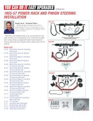
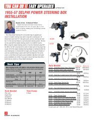
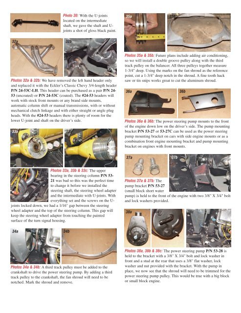
Photo 30: With the U-jointslocated on the intermediateshaft, we gave the shaft <strong>and</strong> U-joints a shot of gloss black paint.35a35b32a32bPhotos 32a & 32b: We have removed the left h<strong>and</strong> header only<strong>and</strong> replaced it with the Eckler’s <strong>Classic</strong> <strong>Chevy</strong> 3/4-length headerP/N 24-53C-LH. This header can be purchased as a pair P/N 24-53 (uncoated) or P/N 24-53C (coated). The #24-53 headers willwork with stock front mounts or any br<strong>and</strong> side mounts,automatic column shift or manual transmissions, with or withoutmechanical clutch linkage <strong>and</strong> with either straight or angle plugheads. With the #24-53 headers there is plenty of room for thelower U-joint <strong>and</strong> shaft on the driver’s side.33a33bPhotos 35a & 35b: Future plans include adding air conditioning,so we will install a double groove pulley along with the thirdt<strong>rack</strong> pulley on the balancer. All three pulleys together measure1-3/4" deep. Using the marks on the fan shroud as the referencepoint, cut a 1-3/4" deep notch in the shroud. A fine tooth hacksaw or tin snips works great to cut the aluminum shroud.36a36bPhotos 36a & 36b: The <strong>power</strong> <strong>steering</strong> pump mounts to the frontof the engine down low on the driver’s side. The pump mountingb<strong>rack</strong>et P/N 53-27 or 53-27C can be used as the <strong>power</strong> <strong>steering</strong>pump mounting b<strong>rack</strong>et on cars with side engine mounts or as acombination front engine mounting b<strong>rack</strong>et <strong>and</strong> pump mountingb<strong>rack</strong>et on engines with front mounts.37a37b33cPhotos 33a, 33b & 33c: The upperbearing in the <strong>steering</strong> column P/N 53-21 was bad so this was the perfect timeto change it before we installed the<strong>steering</strong> shaft, the <strong>steering</strong> wheel adapter<strong>and</strong> the intermediate with U-joints. Witheverything set <strong>and</strong> the screws on the U-joints locked down, we had a 1/16" gap between the <strong>steering</strong>wheel adapter <strong>and</strong> the top of the <strong>steering</strong> column. This gap willkeep the <strong>steering</strong> wheel adapter from touching the paintedsurface of the turn signal housing.Photos 37a & 37b: Thepump b<strong>rack</strong>et P/N 53-27(small block short waterpump) is held to the front of the engine with two 3/8" X 3/4" bolt<strong>and</strong> lock washers provided.38a 38b 38c34a34bPhotos 34a & 34b: A third t<strong>rack</strong> pulley must be added to thecrankshaft to drive the <strong>power</strong> <strong>steering</strong> pump. By adding a thirdt<strong>rack</strong> pulley to the crankshaft, the fan shroud will need to benotched. Mark the shroud <strong>and</strong> remove.Photos 38a, 38b & 38c: The <strong>power</strong> <strong>steering</strong> pump P/N 53-28 isheld to the b<strong>rack</strong>et with a 3/8" X 3/4" bolt <strong>and</strong> lock washer infront <strong>and</strong> a stud at the rear that uses a 3/8" flat washer, lockwasher <strong>and</strong> nut provided with the b<strong>rack</strong>et. With the pump inplace, we now see that the shroud will need to be trimmed for the<strong>power</strong> <strong>steering</strong> pump pulley. This would be true with a big blockor small block engine.