1955-57 power rack and pinion steering - Ecklers Classic Chevy
1955-57 power rack and pinion steering - Ecklers Classic Chevy
1955-57 power rack and pinion steering - Ecklers Classic Chevy
- No tags were found...

You also want an ePaper? Increase the reach of your titles
YUMPU automatically turns print PDFs into web optimized ePapers that Google loves.
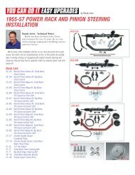
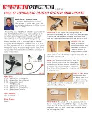
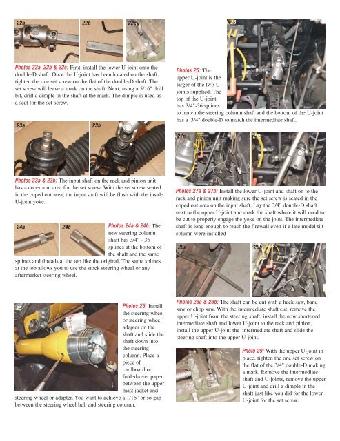
22a 22b 22c26Photos 22a, 22b & 22c: First, install the lower U-joint onto thedouble-D shaft. Once the U-joint has been located on the shaft,tighten the one set screw on the flat of the double-D shaft. Theset screw will leave a mark on the shaft. Next, using a 5/16" drillbit, drill a dimple in the shaft at the mark. The dimple is used asa seat for the set screw.23a23bPhotos 26: Theupper U-joint is thelarger of the two U-joints supplied. Thetop of the U-jointhas 3/4"-36 splinesto match the <strong>steering</strong> column shaft <strong>and</strong> the bottom of the U-jointhas a 3/4" double-D to match the intermediate shaft.27a27bPhotos 23a & 23b: The input shaft on the <strong>rack</strong> <strong>and</strong> <strong>pinion</strong> unithas a coped-out area for the set screw. With the set screw seatedin the coped out area, the input shaft will be flush with the insideU-joint yoke.24a24bPhotos 24a & 24b: Thenew <strong>steering</strong> columnshaft has 3/4" - 36splines at the bottom ofthe shaft <strong>and</strong> the samesplines <strong>and</strong> threads at the top like the original. The same splinesat the top allows you to use the stock <strong>steering</strong> wheel or anyaftermarket <strong>steering</strong> wheel.Photos 27a & 27b: Install the lower U-joint <strong>and</strong> shaft on to the<strong>rack</strong> <strong>and</strong> <strong>pinion</strong> unit making sure the set screw is seated in thecoped out area on the input shaft. Lay the 3/4" double-D shaftnext to the upper U-joint <strong>and</strong> mark the shaft where it will need tobe cut to properly engage the yoke on the joint. The intermediateshaft is long enough to reach the firewall even if a late model tiltcolumn were installed28a28b25Photos 25: Installthe <strong>steering</strong> wheelor <strong>steering</strong> wheeladapter on theshaft <strong>and</strong> slide theshaft down intothe <strong>steering</strong>column. Place apiece ofcardboard orfolded-over paperbetween the uppermast jacket <strong>and</strong><strong>steering</strong> wheel or adapter. You want to achieve a 1/16" or so gapbetween the <strong>steering</strong> wheel hub <strong>and</strong> <strong>steering</strong> column.Photos 28a & 28b: The shaft can be cut with a hack saw, b<strong>and</strong>saw or chop saw. With the intermediate shaft cut, remove theupper U-joint from the <strong>steering</strong> shaft, install the now shortenedintermediate shaft <strong>and</strong> lower U-joint to the <strong>rack</strong> <strong>and</strong> <strong>pinion</strong>,install the upper U-joint the intermediate shaft <strong>and</strong> slide the<strong>steering</strong> shaft into the upper U-joint.Photo 29: With the upper U-joint inplace, tighten the one set screw onthe flat of the 3/4" double-D makinga mark. Remove the intermediateshaft <strong>and</strong> U-joints, remove the upperU-joint <strong>and</strong> drill a dimple in theshaft just like you did for the lowerU-joint for the set screw.