PNOZ X9P Data sheet
PNOZ X9P Data sheet
PNOZ X9P Data sheet
- No tags were found...

You also want an ePaper? Increase the reach of your titles
YUMPU automatically turns print PDFs into web optimized ePapers that Google loves.
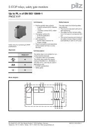
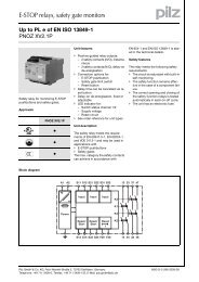
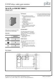
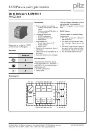
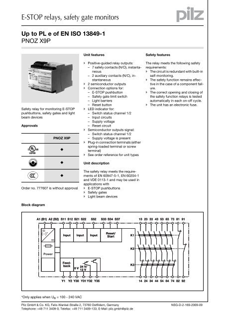
E-STOP relays, safety gate monitorsUp to PL e of EN ISO 13849-1<strong>PNOZ</strong> <strong>X9P</strong>Function description][Funktionen_einkanalig Single-channel operation: no redundancyin the input circuit, earthfaults in the reset and input circuitare detected.][Funktionen_zweikanalig_ohne_quer Dual-channel operation without detectionof shorts across contacts:redundant input circuit, detects– earth faults in the reset and inputcircuit,– short circuits in the input circuitand, with a monitored reset, inthe reset circuit too.][Funktionen_zweikanalig_mit_quer_berTiming diagram Dual-channel operation with detectionof shorts across contacts: redundantinput circuit, detects– earth faults in the reset and inputcircuit,– short circuits in the input circuitand, with a monitored reset, inthe reset circuit too,– shorts between contacts in theinput circuit.][Funktionen_autoStart Automatic start: Unit is active oncethe input circuit has been closed.][Funktionen_manuStart Manual reset: Unit is active oncethe input circuit is closed and thenthe reset circuit is closed.][Funktionen_berStart_allg Monitored reset: Unit is active once– the input circuit is closed andthen the reset circuit is closedand opened again.– the reset circuit is closed andthen opened again once the inputcircuit is closed.][Funktionen_Kontaktvervielfachung Increase in the number of availableinstantaneous safety contacts byconnecting contact expansionmodules or external contactors.][Zeitdiagram_auto_manu_ueber1_aux_semiRUN_semiCH1 23a b a bPOWERReset/StartInputOutput safeOutput aux.Out semi RUNOut semi CHt1 t2 t1 t2t1 t2 t1 t2t1 t2 t1 t2t3Key Power: Supply voltage Reset/Start: Reset circuit S33-S34 Input: Input circuits S11-S12, S21-S22, S52 Output safe: Safety contacts 13-14,23-24, 33-34, 43-44, 53-54, 63-64,73-74 Output aux: Auxiliary contacts 81-82, 91-92Wiring][Verdrahtung_Si_Hi_unverzPlease note: Information given in the “Technicaldetails” must be followed. Outputs 13-14, 23-24, 33-34, 43-44, 53-54, 63-64, 73-74 are safetycontacts, outputs 81-82, 91-92 areauxiliary contacts (e.g. for display). To prevent contact welding, a fuseshould be connected before theoutput contacts (see technical details). Out semi RUN: Semiconductor outputsupply voltage Y35 Out semi CH: Semiconductor outputswitch status Y32 : Automatic reset : Manual reset : Monitored reset a: Input circuit closes before resetcircuit Calculation of the max. cabling runsl max in the input circuit:I max=R lmaxR l/ kmR lmax = max. overall cable resistance(see technical details)R l /km = cable resistance/km Use copper wire that can withstand60/75 °C. b: Reset circuit closes before inputcircuit t 1 : Switch-on delay t 2 : Delay-on de-energisation t 3 : Recovery time Sufficient fuse protection must beprovided on all output contacts withcapacitive and inductive loads.Pilz GmbH & Co. KG, Felix-Wankel-Straße 2, 73760 Ostfildern, GermanyTelephone: +49 711 3409-0, Telefax: +49 711 3409-133, E-Mail: pilz.gmbh@pilz.deNSG-D-2-169-2009-09-2
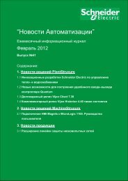
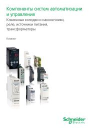
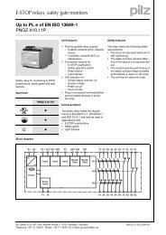
E-STOP relays, safety gate monitorsUp to PL e of EN ISO 13849-1<strong>PNOZ</strong> <strong>X9P</strong> Reset circuitReset circuitAutomatic resetE-STOP/safety gate wiring (single-channeland dual-channel without shorts acrosscontacts)S33E-STOP/safety gate wiring(dual-channel with shorts across contacts)S12S34S34Manual resetS33S3S12S3S34S34Monitored resetS33S34Y1S37S3S12S34Y1S37S3 Feedback circuitFeedback circuitContacts from external contactorsY1Y213 (23 ... 73)14 (24 ... 74)K5K6K5K6L1N Semiconductor outputY31Y32Y35Y3024 V DC/12 V DCSPS InputSPS Input0 V KeyS1/S2S3E-STOP/safety gate switchReset buttonSwitch operatedGate openGate closedPilz GmbH & Co. KG, Felix-Wankel-Straße 2, 73760 Ostfildern, GermanyTelephone: +49 711 3409-0, Telefax: +49 711 3409-133, E-Mail: pilz.gmbh@pilz.deNSG-D-2-169-2009-09-4
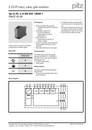
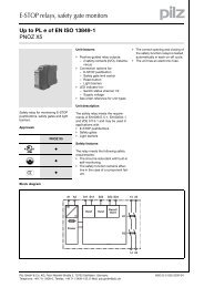
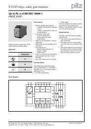
E-STOP relays, safety gate monitorsUp to PL e of EN ISO 13849-1<strong>PNOZ</strong> <strong>X9P</strong>Terminal configurationKlemmenbelegungU B = 12 VDC/24 VDCS11 S12 S12 S21S22Y1 Y2P3A1 S33 S34 S33 81 81 91 13 23 33 43 53 63 73P4P5<strong>PNOZ</strong> <strong>X9P</strong>POWER STARTIN -IN -CH. 1 - OUTCH. 2 - OUT8181 9113 23 33 43 53 63738282 9214 24 34 44 54 6474P4P5A2 Y1 S37 82 82 92 14 24 34 44 54 64 74P3Y30 Y31 Y32 Y35 S11 S52U B = 24 VDC/100 -240 VACS11 S12 S12 S21S22Y1 Y2P3A1 B1 S33 S34 S33 81 81 91 13 23 33 43 53 63 73P4P5<strong>PNOZ</strong> <strong>X9P</strong> ACPOWER STARTIN -IN -CH. 1 - OUTCH. 2 - OUT8181 9113 23 33 43 53 63738282 9214 24 34 44 54 647420162P4P5A2 B2 Y1 S37 82 82 92 14 24 34 44 54 64 74P3Y30 Y31 Y32 Y35 S11 S52InstallationMontage_<strong>PNOZ</strong>_X The safety relay should be installedin a control cabinet with a protectiontype of at least IP54. Use the notch on the rear of the unitto attach it to a DIN rail. Ensure the unit is mounted securelyon a vertical DIN rail (35 mm) by usinga fixing element (e.g. retainingbracket or an end angle).DimensionsAbmessungen* with spring-loaded terminals121 (4.76")94 (3.70") 90(3.54")* 101 (3.98")Pilz GmbH & Co. KG, Felix-Wankel-Straße 2, 73760 Ostfildern, GermanyTelephone: +49 711 3409-0, Telefax: +49 711 3409-133, E-Mail: pilz.gmbh@pilz.deNSG-D-2-169-2009-09
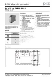
E-STOP relays, safety gate monitorsUp to PL e of EN ISO 13849-1<strong>PNOZ</strong> <strong>X9P</strong>Notice][WICHTIG_PDB_altThis data <strong>sheet</strong> is only intended for useduring configuration. For installationand operation, please refer to the operatinginstructions supplied with theunit.Service life graphD Nennbetriebstrom (A)GB Nominal operating current (A)F Courant coupé (A)ECorriente nominal de servicio (A)I Corrente di esercizio nominale (A)NL Nominale bedrijfsstroom (A)101AC1: 230 VDC13: 24 VLebensdauerkurveAC15: 230 VDC1: 24 VAC1: 400 V0.110 100 1000 10000D Schaltspielzahl x 10 3ENúmero de ciclos x 10 3F Nombre de manœuvres x 10 3 NL Aantal schakelingen x 10 3GB Cycles x 10 3I Numero dei cicli di commutazione x 10 3][Technische Daten <strong>PNOZ</strong>Technical detailsElectrical dataSupply voltageSupply voltage U B AC100 - 240 VSupply voltage U B DC12 V, 24 VVoltage tolerance -15 %/+10 % Order no.: 777606, 777609, 787606, 787609-20 %/+20 % Order no.: 777607Power consumption at U B AC 8.5 VA Order no.: 777606, 787606Power consumption at U B DC 5.5 W Order no.: 777606, 777609, 787606, 7876097.0 W Order no.: 777607Frequency range AC50 - 60 HzResidual ripple DC 160 %Voltage and current atInput circuit DC: 12.0 V Order no.: 777607130.0 mA Order no.: 77760724.0 V Order no.: 777606, 777609, 787606, 78760950.0 mA Order no.: 777606, 777609, 787606, 787609Reset circuit DC: 12.0 V Order no.: 777607100.0 mA Order no.: 777606, 777609, 787606, 78760924.0 V Order no.: 777606, 777609, 787606, 787609200.0 mA Order no.: 777607Feedback loop DC: 12.0 V Order no.: 777607100.0 mA Order no.: 777606, 777609, 787606, 78760924.0 V Order no.: 777606, 777609, 787606, 787609200.0 mA Order no.: 777607Number of output contactsSafety contacts (S) instantaneous: 7Auxiliary contacts (N/C): 2Utilisation category in accordance with EN 60947-4-1Safety contacts: AC1 at 240 VI min : 0.01 A , I max : 8.0 AP max : 2000 VASafety contacts: DC1 at 24 VI min : 0.01 A , I max : 8.0 AP max : 200 WAuxiliary contacts: AC1 at 240 VI min : 0.01 A , I max : 8.0 AP max : 2000 VAAuxiliary contacts: DC1 at 24 VI min : 0.01 A , I max : 8.0 AP max : 200 WUtilisation category in accordance with EN 60947-5-1Safety contacts: AC15 at 230 VI max : 5.0 ASafety contacts: DC13 at 24 V (6 cycles/min)I max : 7.0 AAuxiliary contacts: AC15 at 230 VI max : 5.0 AAuxiliary contacts: DC13 at 24 V (6 cycles/min)I max : 7.0 AContact materialAgSnO2 + 0.2 µm AuPilz GmbH & Co. KG, Felix-Wankel-Straße 2, 73760 Ostfildern, GermanyTelephone: +49 711 3409-0, Telefax: +49 711 3409-133, E-Mail: pilz.gmbh@pilz.deNSG-D-2-169-2009-09-6
E-STOP relays, safety gate monitorsUp to PL e of EN ISO 13849-1<strong>PNOZ</strong> <strong>X9P</strong>Electrical dataExternal contact fuse protection (I K = 1 kA) to EN 60947-5-1Blow-out fuse, quickSafety contacts:10 AAuxiliary contacts:10 ABlow-out fuse, slowSafety contacts:6 AAuxiliary contacts:6 ACircuit breaker 24 VAC/DC, characteristic B/CSafety contacts:6 AAuxiliary contacts:6 ASemiconductor outputs (short circuit proof) 12.0 V Order no.: 77760724.0 V Order no.: 777606, 777609, 787606, 787609 DC,20 mAExternal supply voltage 12.0 V Order no.: 77760724.0 V Order no.: 777606, 777609, 787606, 787609 DCVoltage tolerance -20 %/+20 %Max. overall cable resistance R lmaxinput circuits, reset circuitssingle-channel at U B DC 45 Ohm Order no.: 777606, 777609, 787606, 7876098 Ohm Order no.: 777607single-channel at U B AC 45 Ohm Order no.: 777606, 787606dual-channel without detect. of shorts across contacts at U B DC 15 Ohm Order no.: 77760790 Ohm Order no.: 777606, 777609, 787606, 787609dual-channel without detect. of shorts across contacts at U B AC 90 Ohm Order no.: 777606, 787606dual-channel with detect. of shorts across contacts at U B DC 15 Ohm Order no.: 777606, 777609, 787606, 7876098 Ohm Order no.: 777607dual-channel with detect. of shorts across contacts at U B AC 15 Ohm Order no.: 777606, 787606Safety-related characteristic dataPL in accordance with EN ISO 13849-1 PL e (Cat. 4)Category in accordance with EN 954-1 Cat. 4SIL CL in accordance with EN IEC 62061 SIL CL 3PFH in accordance with EN IEC 620612.31E-09SIL in accordance with IEC 61511 SIL 3PFD in accordance with IEC 615112.03E-06t M in years 20TimesSwitch-on delaywith automatic reset typ. 130 ms Order no.: 777607200 ms Order no.: 777606, 777609, 787606, 787609with automatic reset max. 200 ms Order no.: 777607250 ms Order no.: 777606, 777609, 787606, 787609with automatic reset after power on typ. 150 ms Order no.: 777607220 ms Order no.: 777606, 777609, 787606, 787609with automatic reset after power on max. 220 ms Order no.: 777607300 ms Order no.: 777606, 777609, 787606, 787609with manual reset typ. 150 ms Order no.: 777607200 ms Order no.: 777606, 777609, 787606, 787609with manual reset max. 200 ms Order no.: 777607250 ms Order no.: 777606, 777609, 787606, 787609on monitored reset with falling edge typ. 100 ms Order no.: 777607150 ms Order no.: 777606, 777609, 787606, 787609on monitored reset with falling edge max. 150 ms Order no.: 777607220 ms Order no.: 777606, 777609, 787606, 787609Pilz GmbH & Co. KG, Felix-Wankel-Straße 2, 73760 Ostfildern, GermanyTelephone: +49 711 3409-0, Telefax: +49 711 3409-133, E-Mail: pilz.gmbh@pilz.deNSG-D-2-169-2009-09
E-STOP relays, safety gate monitorsUp to PL e of EN ISO 13849-1<strong>PNOZ</strong> <strong>X9P</strong>Mechanical dataDimensionsHeight 101.0 mm Order no.: 787606, 78760994.0 mm Order no.: 777606, 777607, 777609Width90.0 mmDepth121.0 mmWeight 570 g Order no.: 787609575 g Order no.: 787606580 g Order no.: 777607, 777609585 g Order no.: 777606Technische Daten_Satz NormenThe standards current on 2006-06 apply.][Dauerstrom_ACDCConventional thermal currentNumber of contacts I th (A) at U B DC I th (A) at U B AC1 8.00 A 8.00 A Order no.: 777606, 7876062 8.00 A 8.00 A Order no.: 777606, 7876063 8.00 A 8.00 A Order no.: 777606, 7876064 7.00 A 7.00 A Order no.: 777606, 7876065 6.00 A 6.00 A Order no.: 777606, 7876066 5.50 A 5.50 A Order no.: 777606, 7876067 5.00 A 5.00 A Order no.: 777606, 787606BestelldatenOrder referenceType Features Terminals Order no.<strong>PNOZ</strong> <strong>X9P</strong> C 110 - 240 VAC 24 VDC Spring-loaded terminals 787 606<strong>PNOZ</strong> <strong>X9P</strong> 110 - 240 VAC 24 VDC Screw terminals 777 606<strong>PNOZ</strong> <strong>X9P</strong> C 24 VDC Spring-loaded terminals 787 609<strong>PNOZ</strong> <strong>X9P</strong> 24 VDC Screw terminals 777 609<strong>PNOZ</strong> <strong>X9P</strong> 12 VDC Screw terminals 777 607Pilz GmbH & Co. KG, Felix-Wankel-Straße 2, 73760 Ostfildern, GermanyTelephone: +49 711 3409-0, Telefax: +49 711 3409-133, E-Mail: pilz.gmbh@pilz.deNSG-D-2-169-2009-09