
You also want an ePaper? Increase the reach of your titles
YUMPU automatically turns print PDFs into web optimized ePapers that Google loves.
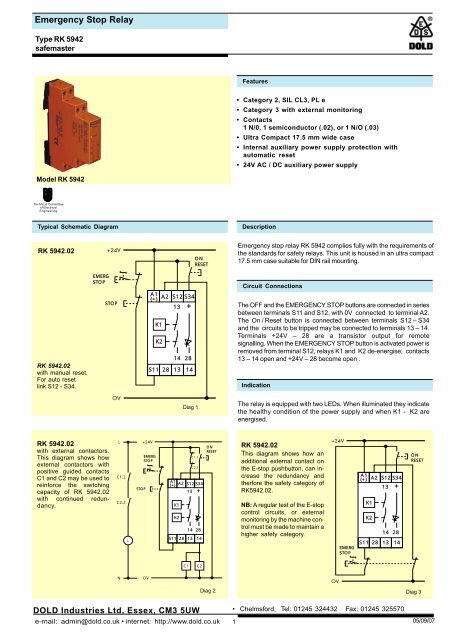
<strong>Emergency</strong> <strong>Stop</strong> <strong>Relay</strong>Type RK 5942safemasterFeatures• Category 2, SIL CL3, PL e• Category 3 with external monitoring• Contacts1 N/0, 1 semiconductor (.02), or 1 N/O (.03)• Ultra Compact 17.5 mm wide case• Internal auxiliary power supply protection withautomatic reset• 24V AC / DC auxiliary power supplyModel RK 5942Technical Committeeof ElectricalEngineeringTypical Schematic Diagram DescriptionRK 5942.02RK 5942.02with manual reset.For auto resetlink S12 - S34.EMERGSTOPSTOPA1(+)A2 S12 S3413K1K2S11 2814 2813+14ONRESET<strong>Emergency</strong> stop relay RK 5942 complies fully with the requirements ofthe standards for safety relays. This unit is housed in an ultra compact17.5 mm case suitable for DIN rail mounting.Circuit ConnectionsThe OFF and the EMERGENCY STOP buttons are connected in seriesbetween terminals S11 and S12, with 0V connected to terminal A2.The On / Reset button is connected between terminals S12 – S34and the circuits to be tripped may be connected to terminals 13 – 14.Terminals +24V – 28 are a transistor output for remotesignalling. When the EMERGENCY STOP button is activated power isremoved from terminal S12, relays K1 and K2 de-energise, contacts13 – 14 open and +24V – 28 become open .IndicationDiag 1The relay is equipped with two LEDs. When illuminated they indicatethe healthy condition of the power supply and when K1 - K2 areenergised.RK 5942.02with external contactors.This diagram shows howexternal contactors withpositive guided contactsC1 and C2 may be used toreinforce the switchingcapacity of RK 5942.02with continued redundancy.LC1.2C2.2LSTOPEMERGSTOPA1(+)K1K2A2 S12 S341314 28S11 28 13C1.1C2.1+14ONRESETRK 5942.02This diagram shows how anadditional external contact onthe E-stop pushbutton, can increasethe redundancy andtherfore the safety category ofRK5942.02.NB: A regular test of the E-stopcontrol circuits, or externalmonitoring by the machine controlmust be made to maintain ahigher safety category.EMERGSTOPA1(+)K1K2S11 28A2 S12 S341314 2813+14ONRESETC1C2NDiag 2Diag 3DOLD Industries Ltd, Essex, CM3 5UWe-mail: admin@dold.co.uk • internet: http://www.dold.co.uk• Chelmsford, Tel: 01245 324432 Fax: 01245 325570105/09/07
<strong>Emergency</strong> <strong>Stop</strong> <strong>Relay</strong>Type RK 5942safemasterRK 5942.02 with LG5929.60 Extension Modules+24VEMERGSTOPONRESETSTOPA1(+)K1K2A2 S12 S3413+A1 13K1K22333 43 53Y1A1 13K1K22333 43 53Y114 28S11 281314A2 14 24 34 44 54 Y2A2 14 24 34 44 54 Y20VRK 5942.02 LG5929.60 LG5929.60Diag 4Specifications Terminal LayoutNominal Voltage (Vn) 24Vac/dcBurden 5.5VA ac,2.2W dcVoltage Tolerance 0.8... 1.1Vn ac, 0.8… 1.2Vn dcControl Voltage 24V dcContacts 1N/O, 1 S/C or 1N/OMax Switching Capacity 5A ac (cos ø 1 – 0.7)5A dc see dataContinuous Current Rating see dataContact Life Mechanical 30 x 10 6 operationsSemiconductor Rating 24Vdc, 100mAContact Life Electrical see dataDerating Capacity AC15, 3A, 250V ac(for Heavy Inductive Loads) DC13, 4A, 24V dcMin Switching Voltage & Current 10V, 15mA ac/dcMax Switching Voltage 250V ac, 250V dcMax Switching Power 1200VA (AC1) 192W dcMax Switching Frequency 600 operations/hourReaction Times Reset 80msE-STOP