E-STOP relays, safety gate monitors
E-STOP relays, safety gate monitors
E-STOP relays, safety gate monitors
- No tags were found...

Create successful ePaper yourself
Turn your PDF publications into a flip-book with our unique Google optimized e-Paper software.
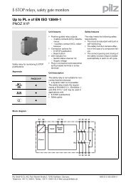
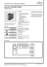
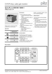
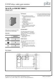
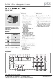
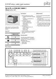
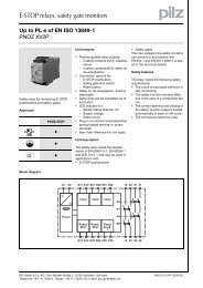
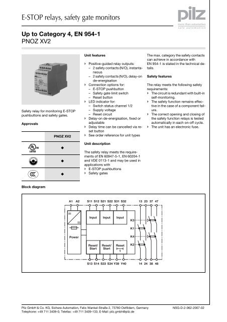
E-<strong>STOP</strong> <strong>relays</strong>, <strong>safety</strong> <strong>gate</strong> <strong>monitors</strong>Up to Category 4, EN 954-1PNOZ XV2Function description Single-channel operation: no redundancyin the input circuit, earthfaults in the reset circuit are detected. Dual-channel operation with detectionof shorts across contacts: redundantinput circuit, detectsTiming diagram– earth faults in the reset and inputcircuit,– short circuits in the input circuitand, with a monitored reset, inthe reset circuit too,– shorts between contacts in theinput circuit. Automatic start: Unit is active oncethe input circuit has been closed. Monitored reset: Unit is active oncethe input circuit is closed and oncethe reset circuit is closed after thewaiting period has elapsed(see technical details). Increase in the number of availablecontacts by connecting contact expandermodules or external contactors/<strong>relays</strong>.1 2POWERReset/StartReset t vInputOutput safeOutput safe delt1 t2 t3 t1 t2 t3 t4 t1 t2 t3 t5 t4 t1 t2 t3Key Power: Supply voltage Reset/start: Reset circuit S13-S14,S33-S34 Reset t v : Y39-Y40 Input: Input circuits S11-S12, S21-S22, S31-S32WiringPlease note: Information given in the “Technicaldetails” must be followed. Outputs 13-14, 23-24 are instantaneous<strong>safety</strong> contacts, outputs 37-38, 47-48 are delay-on de-energisation<strong>safety</strong> contacts. To prevent contact welding, a fuseshould be connected before theoutput contacts (see technical details). Calculation of the max. cable runsl max in the input circuit: Output safe: Safety contacts, instantaneous13-14, 23-24 Output safe del: Safety contacts,delayed 37-38, 47-48 : Automatic reset : Monitored reset Sufficient fuse protection must beprovided on all output contacts withcapacitive and inductive loads. t 1 : Switch-on delay t 2 : Delay-on de-energisation t 3 : Delay time t 4 : Waiting period t 5 : Recovery timeI max=R lmaxR l/ kmR lmax = max. overall cable resistance(see technical details)R l / km = cable resistance/km Use copper wire that can withstand60/75 °C.Pilz GmbH & Co. KG, Sichere Automation, Felix-Wankel-Straße 2, 73760 Ostfildern, GermanyTelephone: +49 711 3409-0, Telefax: +49 711 3409-133, E-Mail: pilz.gmbh@pilz.deNSG-D-2-062-2007-02-2
E-<strong>STOP</strong> <strong>relays</strong>, <strong>safety</strong> <strong>gate</strong> <strong>monitors</strong>Up to Category 4, EN 954-1PNOZ XV2Preparing for operation Supply voltageSupply voltage AC DCA1 L+A2 L- Input circuitInput circuit Single-channel Dual-channelE-<strong>STOP</strong>without detection of shorts across contactsS21S12S11S1S22S32S31E-<strong>STOP</strong>with detection of shorts across contactsS22S1S11S32S12S31S21Safety <strong>gate</strong>without detection of shorts across contactsS12S1S21S11S22S32S31Safety <strong>gate</strong>with detection of shorts across contactsS11S22S21S1S2S12S32S31Pilz GmbH & Co. KG, Sichere Automation, Felix-Wankel-Straße 2, 73760 Ostfildern, GermanyTelephone: +49 711 3409-0, Telefax: +49 711 3409-133, E-Mail: pilz.gmbh@pilz.deNSG-D-2-062-2007-02
E-<strong>STOP</strong> <strong>relays</strong>, <strong>safety</strong> <strong>gate</strong> <strong>monitors</strong>Up to Category 4, EN 954-1PNOZ XV2 Reset circuitReset circuitAutomatic resetE-<strong>STOP</strong> wiring (single-channel)Safety <strong>gate</strong> (single-channel)S13E-<strong>STOP</strong> wiring (dual-channel)Safety <strong>gate</strong> (dual-channel)S14S13S14S1S2Monitored resetS33S34S13S14S3S33S34S13S14S3 Reset delay timeReset Without reset With resetLink or N/C contactY39Y39Y40Y40 Feedback loopFeedback loop Automatic reset Monitored resetContacts from external contactorsS13S1413 (23)14 (24)K5K6K5K6L1NS33S3413 (23)14 (24)K5S3K6K5K6L1N KeyS1/S2S3E-<strong>STOP</strong>/<strong>safety</strong> <strong>gate</strong> switchReset buttonSwitch operatedGate openGate closedPilz GmbH & Co. KG, Sichere Automation, Felix-Wankel-Straße 2, 73760 Ostfildern, GermanyTelephone: +49 711 3409-0, Telefax: +49 711 3409-133, E-Mail: pilz.gmbh@pilz.deNSG-D-2-062-2007-02-4
E-<strong>STOP</strong> <strong>relays</strong>, <strong>safety</strong> <strong>gate</strong> <strong>monitors</strong>Up to Category 4, EN 954-1PNOZ XV2Terminal configurationInstallationDimensions The <strong>safety</strong> relay should be installedin a control cabinet with a protectiontype of at least IP54. Use the notch on the rear of the unitto attach it to a DIN rail. Ensure the unit is mounted securelyon a vertical DIN rail (35 mm) by usinga fixing element (e.g. retainingbracket or an end angle).121 (4.76")75 (2.95")87 (3.42")45(1.77")Pilz GmbH & Co. KG, Sichere Automation, Felix-Wankel-Straße 2, 73760 Ostfildern, GermanyTelephone: +49 711 3409-0, Telefax: +49 711 3409-133, E-Mail: pilz.gmbh@pilz.deNSG-D-2-062-2007-02
E-<strong>STOP</strong> <strong>relays</strong>, <strong>safety</strong> <strong>gate</strong> <strong>monitors</strong>Up to Category 4, EN 954-1PNOZ XV2NoticeService life graphThis data sheet is only intended for useduring configuration. For installationand operation, please refer to the operatinginstructions supplied with theunit.D Nennbetriebstrom (A)GB Nominal operating current (A)F Courant coupé (A)E Corriente nominal de servicio (A)I Corrente di esercizio nominale (A)NL Nominale bedrijfsstroom (A)101AC15: 230 VDC13: 24 VDC1: 24 VAC1: 230 V0.110 100 1000 10000D Schaltspielzahl x 10 3E Número de ciclos x 10 3F Nombre de manœuvres x 10 3 NL Aantal schakelingen x 10 3GB Cycles x 10 3I Numero dei cicli di commutazione x 10 3Technical detailsElectrical dataSupply voltageSupply voltage U B DC24 VVoltage tolerance -15 %/+10 %Power consumption at U B DC4.5 WResidual ripple DC 160 %Voltage and current atInput circuit DC: 24.0 V35.0 mAReset circuit DC: 24.0 V40.0 mAFeedback loop DC: 24.0 V3.5 mANumber of output contactsSafety contacts (S) instantaneous: 2Safety contacts (N/O), delayed: 2Category of output contacts in accordance with EN 954-1Safety contacts (S) instantaneous: 4Delay time
E-<strong>STOP</strong> <strong>relays</strong>, <strong>safety</strong> <strong>gate</strong> <strong>monitors</strong>Up to Category 4, EN 954-1PNOZ XV2Electrical dataExternal contact fuse protection (I K = 1 kA) to EN 60947-5-1Blow-out fuse, quickSafety contacts:10 ASafety contacts, delayed:10 ABlow-out fuse, slowSafety contacts:6 ASafety contacts, delayed:6 ACircuit breaker 24 VAC/DC, characteristic B/CSafety contacts:6 ASafety contacts, delayed:6 AMax. overall cable resistance R lmaxinput circuits, reset circuitssingle-channel at U B DC100 Ohmdual-channel with detect. of shorts across contacts at U B DC 10 OhmTimesSwitch-on delaywith automatic reset typ.350 mswith automatic reset max.650 mswith automatic reset after power on typ.385 mswith automatic reset after power on max.700 mson monitored reset with rising edge typ.35 mson monitored reset with rising edge max.70 msDelay-on de-energisationwith E-<strong>STOP</strong> typ.15 mswith E-<strong>STOP</strong> max.30 mswith power failure typ.85 mswith power failure max.200 msRecovery time at max. switching frequency 1/safter E-<strong>STOP</strong>50 ms +tvafter power failure250 msDelay time t V : selectable 0,00 s; 0,50 s; 1,00 s; 2,00 s; 4,00 s; 6,00 s; 8,00 s; 10,00 s; 15,00s; 20,00 s; 25,00 s; 30,00 s Order no.: 7745000,10 s; 0,20 s; 0,30 s; 0,40 s; 0,50 s; 0,60 s; 0,70 s; 0,80 s; 1,00 s;1,50 s; 2,00 s; 3,00 s Order no.: 7745020,00 s; 5,00 s; 10,00 s; 20,00 s; 40,00 s; 60,00 s; 80,00 s; 100,00s; 150,00 s; 200,00 s; 250,00 s; 300,00 s Order no.: 774508Delay time t V : fixed 0.50 s Order no.: 77450410.00 s Order no.: 7745063.00 s Order no.: 774505Repetition accuracy 2 %Time accuracy-15% / +15% +50 msWaiting period with a monitored resetwith rising edge300 msMin. start pulse duration with a monitored resetwith rising edge30 msSimultaneity, channel 1 and 2∞Supply interruption before de-energisation20 msEnvironmental dataEMC EN 60947-5-1, EN 61000-6-2Vibration to EN 60068-2-6Frequency10 - 55 HzAmplitude0.35 mmClimatic suitability EN 60068-2-78Airgap creepage in accordance with EN 60947-1Pollution degree 2Rated insulation voltage250 VRated impulse withstand voltage4.0 kVAmbient temperature -10 - 55 °CPilz GmbH & Co. KG, Sichere Automation, Felix-Wankel-Straße 2, 73760 Ostfildern, GermanyTelephone: +49 711 3409-0, Telefax: +49 711 3409-133, E-Mail: pilz.gmbh@pilz.deNSG-D-2-062-2007-02
E-<strong>STOP</strong> <strong>relays</strong>, <strong>safety</strong> <strong>gate</strong> <strong>monitors</strong>Up to Category 4, EN 954-1PNOZ XV2Environmental dataStorage temperature -40 - 85 °CProtection typeMounting (e.g. cabinet)IP54HousingIP40TerminalsIP20Mechanical dataHousing materialHousingPPO UL 94 V0FrontABS UL 94 V0Max. cross section of external conductors with screw terminals1 core flexible 0.20 - 4.00 mm² , 24 - 10 AWG2 core, same cross section, flexible:with crimp connectors, without insulating sleeve0.20 - 2.50 mm² , 24 - 14 AWGwithout crimp connectors or with TWIN crimp connectors 0.20 - 2.50 mm² , 24 - 14 AWGTorque setting with screw terminals0.60 NmDimensionsHeight87.0 mmWidth45.0 mmDepth121.0 mmWeight 340 g Order no.: 774504, 774505, 774506350 g Order no.: 774500, 774502, 774508The standards current on 11/03 apply.Conventional thermal currentI th (A) at U B DC1 contact 8.00 A2 contacts 6.80 A3 contacts 5.50 A4 contacts 4.80 AOrder referenceType Features Terminals Order no.PNOZ XV2 24 VDC 0.5 s fixed Screw terminals 774 504PNOZ XV2 24 VDC 3.0 s fixed Screw terminals 774 505PNOZ XV2 24 VDC 10.0 s fixed Screw terminals 774 506PNOZ XV2 24 VDC 3 s selectable Screw terminals 774 502PNOZ XV2 24 VDC 30 s selectable Screw terminals 774 500PNOZ XV2 24 VDC 300 s selectable Screw terminals 774 508Pilz GmbH & Co. KG, Sichere Automation, Felix-Wankel-Straße 2, 73760 Ostfildern, GermanyTelephone: +49 711 3409-0, Telefax: +49 711 3409-133, E-Mail: pilz.gmbh@pilz.deNSG-D-2-062-2007-02-8