MPH series video encoders - Teleste
MPH series video encoders - Teleste
MPH series video encoders - Teleste
- No tags were found...

Create successful ePaper yourself
Turn your PDF publications into a flip-book with our unique Google optimized e-Paper software.
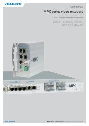
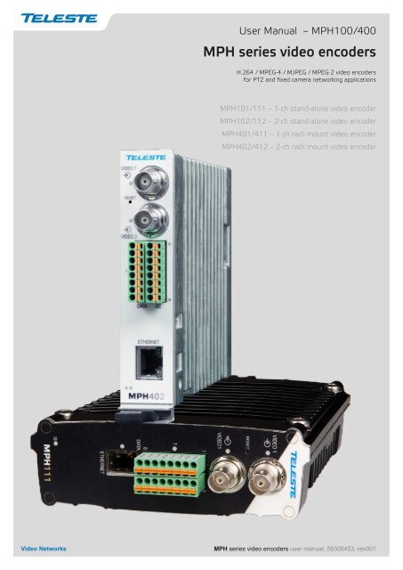
User Manual – <strong>MPH</strong>100/400<strong>MPH</strong> <strong>series</strong> <strong>video</strong> <strong>encoders</strong>H.264 / MPEG-4 / MJPEG / MPEG-2 <strong>video</strong> <strong>encoders</strong>for PTZ and fixed camera networking applications<strong>MPH</strong>101/111 – 1-ch stand-alone <strong>video</strong> encoder<strong>MPH</strong>102/112 – 2-ch stand-alone <strong>video</strong> encoder<strong>MPH</strong>401/411 – 1-ch rack mount <strong>video</strong> encoder<strong>MPH</strong>402/412 – 2-ch rack mount <strong>video</strong> encoder<strong>MPH</strong> <strong>series</strong> <strong>video</strong> <strong>encoders</strong> user manual, 59300453, rev001
Contents<strong>MPH</strong> Series Video Encoders Introduction.............................................................................................................. 1General............................................................................................................................................................... 1Firmware version................................................................................................................................................. 1<strong>MPH</strong> Series Video Encoders Front and Rear Panel............................................................................................2-3<strong>MPH</strong>100/400 <strong>series</strong> <strong>video</strong> <strong>encoders</strong> mechanical connections........................................................................... 3Getting started........................................................................................................................................................... 4Quick instructions................................................................................................................................................ 4Device’s IP address............................................................................................................................................. 4<strong>MPH</strong>100/400 Series Combinatios............................................................................................................................. 5Ethernet Interface...................................................................................................................................................6-7Ethernet connections.......................................................................................................................................... 6Fixed electrical interface..................................................................................................................................... 6Power over Ethernet (PoE) option....................................................................................................................... 6Optical interface.................................................................................................................................................. 6Management Interface............................................................................................................................................... 8General............................................................................................................................................................... 8WebUI................................................................................................................................................................. 8ONVIF................................................................................................................................................................. 8CLI – Command Line Interface........................................................................................................................... 8Web user interface (WebUI)...................................................................................................................................... 9General............................................................................................................................................................... 9System requirements for WebUI......................................................................................................................... 9Operation............................................................................................................................................................ 9Starting WebUI session.................................................................................................................................... 10User levels and permissions............................................................................................................................. 10Configuring Video Channels..............................................................................................................................12-20Video connection.............................................................................................................................................. 12Video channel configuration.............................................................................................................................. 12Video streaming methods................................................................................................................................. 12Media profile...................................................................................................................................................... 13Video Interfaces ............................................................................................................................................... 14Video Source and Sinks ................................................................................................................................... 15Video Encoders ................................................................................................................................................ 16Video stream multiplication............................................................................................................................... 19Video streaming performance........................................................................................................................... 20Configuring Data Channels................................................................................................................................23-27Data connections.............................................................................................................................................. 23Data type descriptions...................................................................................................................................... 24Data termination and biasing............................................................................................................................ 24Data interfaces configuration ........................................................................................................................... 25Data 1 & 2 (WebUI)........................................................................................................................................... 25Tunneling Protocol............................................................................................................................................ 26ONVIF PTZ service .......................................................................................................................................... 27Configuring Contact Closure Channels...........................................................................................................28-30Contact closure loop (CCL) connection............................................................................................................ 28Contact closure inputs...................................................................................................................................... 28Contact closure output...................................................................................................................................... 28Video Analytics Configurations ............................................................................................................................ 31Metadata Configurations......................................................................................................................................... 32Network Settings......................................................................................................................................................34Date & Time Settings............................................................................................................................................... 35Device Management................................................................................................................................................ 36Services Settings..................................................................................................................................................... 37User management.................................................................................................................................................... 38Command Line Interface - CLI................................................................................................................................ 39General.............................................................................................................................................................39System requirements for CLI............................................................................................................................ 39Connection methods - Local serial connection................................................................................................. 40Connection methods - TCP/IP.......................................................................................................................... 41Detailed descriptions of CLI commands........................................................................................................... 42<strong>MPH</strong> features............................................................................................................................................................ 47Copyright acknowledgements................................................................................................................................50
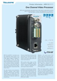
<strong>MPH</strong> Series Video Encoders Front and Rear Panel<strong>MPH</strong>100 stand-alone encoder (example view from <strong>MPH</strong>111 device)5GroundVIDEO 1RESETReset buttonM - Led. Power andstatus indicator ledVIDEO 119T8 16DATACCMETHERNET<strong>MPH</strong>111T - Led. Terminalserver indicator ledM - Led. Power andstatus indicator led5Ground12...24 VDC_+GNDFront panel1 2 3 4Back panel<strong>MPH</strong>400 rack mount encoder (example view from <strong>MPH</strong>402 device)VIDEO 1RESETReset button1VIDEO 2192512...24 VDC_+T8 16DATA CCT - Led. Terminalserver indicator led3Back panelETHERNET4M<strong>MPH</strong>402Front panelM - Led. Power andstatus indicator led62 <strong>MPH</strong>100/400 <strong>series</strong> <strong>video</strong> <strong>encoders</strong> WebUI user manual
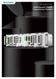
D x2 C C x2 E x1<strong>MPH</strong>100/400 <strong>series</strong> <strong>video</strong> <strong>encoders</strong> mechanical connections1. Video input 1 (BNC female) and indicator led.2. Video input 2 (BNC female) for 2-ch versions orVideo loop through port for 1-ch versions and indicator led.3. 16-pin screw terminal and T indicator led:Data interfaces, EIA RS422/485 (data1), EIA RS232 (data 2) /managementinterface (CLI) or general purpose serial port.Contact closure interfaces (cc input 1, cc input 2, cc output)4. Ethernet interface, fixed (RJ-45 female) or socket for SFP module(available with a variety of types).5. Power supply connector (2-pin screw terminal, +12...28 VDC).6. Handle (<strong>MPH</strong>400 <strong>series</strong> only).Reset button: Device software reboot and hard/soft factorydefaults restoration (see section Factory reset).Ground: Device ground connection.Led Colour ModeOFF / DarkPower offYellowDevice starts upRedDevice self-test failedM GreenPower on / Device is functionalBlinking GreenDevice is being accessed from any interface.Whenever device is accesed from WebUI, CLI or ONVIFinterface, led blinks 2s. During software update, LED willblink throughout the firmware image transfer duration.M - (module/power led) LED indicator operation. This LED indicates powerstatus, factory reset, interface activity.Factory resetThe factory reset can be done via WebUI, CLI, or using the pin-hole resetbutton on the front panel of device. There are two types of factory resets;Soft factory and Hard factory reset. The Soft factory reset restores all,except IP configuration to the default factory settings. The Hard factoryreset restores all settings to default factory settings.Reset pinholeThe reset pinhole is a button that resets the device to its original defaultsettings. To use this button, insert a stiff wire (such as a straightened paperclip) into the pinhole. If you release the button immediately the device willreboot with current settings. But if you hold the button you can restore thedefault settings as following table shows.Led Colour ModeM6 x (short) green blinks atboot time2 x (short) red blinks24 x yellow blinks at boot time(after the 6 green blinks)4 x (short) red blinksTime window to select Soft factory reset.If reset button is released in this time window, softfactory reset is selected.Soft factory reset shall be applied.Wait until device has fully started (power led green).Time window to select Hard factory reset.If reset button is released in this time window, hardfactory reset is selected.Hard factory reset shall be applied.Wait until device has fully started (power led green).<strong>MPH</strong>100/400 <strong>series</strong> <strong>video</strong> <strong>encoders</strong> WebUI user manual 3
Getting startedQuick instructions11234Install the temperature hardened stand-alone <strong>MPH</strong>100 <strong>series</strong> encoder tothe installation location. A +12 V supply voltage is provided by a CPS25x<strong>series</strong> power supply (see example picture beside), or alternately throughthe LAN cable (CAT5) when using Power over Ethernet (PoE) technology.Install the rack mount <strong>MPH</strong>400 <strong>series</strong> encoder into a MSR416 installationframe equipped with a MPS12x <strong>series</strong> power supply.Connect all needed signals to their respective connectors on thedevice’s front panel:• Data and contact closure signals to the screw terminal connector.• CVBS <strong>video</strong> signals to the BNC female connector(s).• Ethernet network to Ethernet connector.Switch on the power and wait until the power led “M” lits green (start-uptime approx. 100 secs). This indicates that the device hardware isoperating properly and ready for usage.Note! If led doesn’t lit green, refer to “M- LED indicator” section toknow the status of the device.Log on to the device using the IP address assigned by DHCP server,or locally from a Mgmt port (CLI) and then set all necessary settings inthe device.Note! If network doesn’t contain DHCP server, then the <strong>MPH</strong> <strong>encoders</strong>hall use Zeroconf (link-local) as DHCP fallback.Device’s IP addressThere are two ways of assigning IP address to the <strong>MPH</strong> device. The IPaddress can be automatically assigned via DHCP, or you can set itmanually as a static IP address. Factory default IP settings for thedevice is DHCP enabled.By default when you have DHCP server in the network, DHCP serverassigns an IP address automatically to the <strong>MPH</strong> encoder. The DHCP serveroffers an IP address from its address pool when a device is starting up.CPS25x <strong>series</strong> powersupply for <strong>MPH</strong>100 device.If DHCP server is not available device uses zero configuration (link-localaddress) as DHCP fallback. With Zeroconf protocol <strong>MPH</strong> chooses an IPaddress randomly in the IP range from 169.254.0.1 to 169.254.255.254.Alternatively you can manually assign the IP address, subnet mask andgateway address to the unit.If there is no DHCP address in the network, the unit chooses randomlyan IP address from the private IP range 169.254.0.1 - 169.254.255.254.In this case in order to find the chosen IP address you have two options.You can use <strong>Teleste</strong> <strong>MPH</strong> Discovery Tool to browse all the availableONVIF compliment devices in the network, note that your PC IP addressshould be in the same IP range. Second option is, connecting to the<strong>MPH</strong> device locally via the serial port and use the CLI (Command LineInterface) to see device IP address.See section Network command to see how to change IP address via CLI.4 <strong>MPH</strong>100/400 <strong>series</strong> <strong>video</strong> <strong>encoders</strong> WebUI user manual
<strong>MPH</strong>100/400 Series CombinatiosElectrical RJ-45 Ethernet interface.Small form-factor pluggable (SFP) Ethernet interface.One <strong>video</strong> input.Two <strong>video</strong> inputs.One <strong>video</strong> input.Two <strong>video</strong> inputs.VIDEO 1VIDEO 1VIDEO 1VIDEO 1RESETRESETRESETRESETVIDEO 1VIDEO 2VIDEO 1VIDEO 219191919Stand-alone. Rack-mounted.T8 16DATACCETHERNETM<strong>MPH</strong>101VIDEO 1RESETVIDEO 119T8 16DATA CCT8 16DATACCETHERNETM<strong>MPH</strong>102VIDEO 1RESETVIDEO 219T8 16DATA CCT8 16DATACCETHERNETM<strong>MPH</strong>111T8 16DATACCETHERNETM<strong>MPH</strong>112VIDEO 1RESETVIDEO 219T8 16DATACCETHERNETETHERNETETHERNETM<strong>MPH</strong>401M<strong>MPH</strong>402M<strong>MPH</strong>412<strong>MPH</strong>100/400 <strong>series</strong> <strong>video</strong> <strong>encoders</strong> WebUI user manual 5
Ethernet InterfaceEthernet connectionsElectrical Ethernet connector (RJ-45).<strong>MPH</strong> encoder supports both Fast Ethernet and Gigabit Ethernet connectionspeeds. Ethernet interface type is either a fixed electrical (copper), orhas support for a small form-factor pluggable transceiver (SFP) module.Supported SFP transceivers are specified by <strong>Teleste</strong>. Please see the latestlits of available products.Led Colour Mode21GreenBlinking GreenOFF / DarkOrangeOFF / DarkLink upTrafficNo link1000 Mbps100 MbpsEthernet port’s led indicator operation(RJ-45 connector).Led Colour ModeSFPGreenBlinking GreenOFF / DarkLink upTrafficNo linkEthernet port’s led indicator operation(when SFP optical connector).Fixed electrical interfaceThe electrical Ethernet connector type is a RJ-45 female. The connector isfixed (except Gigabit model with GTA/GTR type of SFP). Depending onthe model, the Ethernet interface speed is 10/100BASE-T (Fast Ethernet)or 10/100/1000BASE-T (Gigabit Ethernet).Power over Ethernet (PoE) option<strong>MPH</strong>100 <strong>series</strong> <strong>encoders</strong> supports PoE standard (802.3af). This meansthat the <strong>encoders</strong> can be powered through the LAN cable (CAT5) withoutthe need of individual power supplies.Requirements for the use of PoE:• A Power over Ethernet (PoE) compliant switch or hub.• MLH251 license activation.INVISIBLE LASERRADIATIONCLASS 1Note! 100BASE-FX SFP module isalways supported, 1000BASE-X SFPmodule has to be activated with therequired license (MLH241).Optical interfaceThe optical Ethernet interface is type of a small form-factor pluggable(SFP). SFP modules for optical Ethernet operation are available with avariety of different types, allowing users to select the suitable module forto provide the required optical reach over the available optical fibre type.The optical connector type is LC (single or dual). Depending on themodel, the Ethernet interface speed is 100BASE-F (Fast Ethernet) or1000BASE-X (Gigabit Ethernet). The optical output level is constant andcannot be adjusted.When installing the fibre optic cable, do not exceed the minimumbending radius when connecting cable to the system.Optical Ethernet connection meets class 1 laser safety requirements ofIEC 60825-2: 2004 and US department of health services 21 CFR1040.10 and 1040.11 (1990) when operated within the specified temperature,power supply and duty cycle ranges.6 <strong>MPH</strong>100/400 <strong>series</strong> <strong>video</strong> <strong>encoders</strong> WebUI user manual
How to unplug or plug-in the SFP transceiver moduleIf your up-link port requirements change, simply unplug the existing SFPmodule, and plug-in the new module. The SFP transceiver modulesmust be installed before the encoder is powered on.2 fibre version 1 fibre versionTx Rx Tx/RxSFP plug-in optical transceiver module.The SFP transceiver module has a bale-clasp latch that makes easier toinstall or remove the module. Protect the SFP module by inserting aclean dustplug into the module after you remove the fiber cable. Be sureto clean the optic surfaces of the fiber cable before you plug the cableinto another module. When using 2 fibre version SFP, select carefullythe correct optical port for TX and RX operation.To unplug and plug-in the SFP module, follow these steps1. Open the bale clasp on the SFP module by pressing the claspdownward until it is in a horizontal position.2. Use a small flat-blade screwdriver or other long, narrow instrument topush on the hinge pin to unlock the SFP cage latch.Optical connector is the type of LC.3. Grasp the SFP module by the bale clasp and gently pull it out of theSFP cage.To plug-in the module:1. Orient the transceiver with the bale clasp on the bottom, close thebale clasp by pushing it up over the transceiver, then gently insertthe transceiver into the port until it clicks into place.bale claspNote! Reboot the device when the SFP is changed.Some generic notes for successfull optical connections:latchSFP module’s locking release points.• Ensure that the fiber patch cord is damage-free (fiber condition canbe easily checked by a visible laser tester)• Do not exceed the minimum bending radius of the fibre• Avoid sharp corners on cable shelves and in cable managementin overall• Make sure that correct optical connectors are used• Open connectors are always secured by dustcaps during maintenance• Always before mating clean all connectors (wet cleaning by highpurity alcohol & drying, or dry cleaning with reel-based lint-free wipes,fiber adapters may require special ferrule end-face cleaning tools)• Before making any visual inspections ensure that system has beenshutdown or no optical power is present• For fault finding at least a optical power meter is required, a complexfiber cable environment may require use of an OTDR equipment<strong>MPH</strong>100/400 <strong>series</strong> <strong>video</strong> <strong>encoders</strong> WebUI user manual 7
Management Interface9 10 11 12 13 14 15 16General<strong>MPH</strong> <strong>encoders</strong> support web user interface (WebUI), ONVIF configurationinterface and command line user interface (CLI) for various configurationpurposes.1 2 3 4 5 6 7 8PC/PSIONReceivedataTransmitdataSystemgroundD9femaleScrewterminal2 63 7DATA 2 TXDATA 2 RXDATA 2 GND<strong>MPH</strong>encoderMgmtoutputMgmtinput5 8 GroundLocal management connection (CLI)and management cable (CIC506)pinout (D9 female/screw terminal).WebUI<strong>MPH</strong> <strong>series</strong> <strong>video</strong> <strong>encoders</strong> can be fully configured using Web user interface(WebUI). You can access the Web user interface via web browser.ONVIF<strong>MPH</strong> <strong>series</strong> <strong>video</strong> encoder support ONVIF (Open Network VideoInterface Forum) global interface (version 1.02).CLI – Command Line Interface<strong>MPH</strong> <strong>series</strong> <strong>video</strong> encoder include a command line interface (CLI) forconfiguration purposes. The CLI is a text-based interface that allows theuser to interact with the operating system by entering commands andoptional arguments. CLI is accessible through any terminal emulatorapplication (e.g. Hyper Terminal or PuTTY). The command structure isthe same for all session types. A typical CLI usage is to access thedevice IP address settings. By default the data channel 2 is set for CLIusage. The data channel 2 can be set to normal RS232 data mode withWebUI when needed.Note! Data 2 channel can be set either general RS232 datatransport mode or CLI mode (not simultaneously). The defaultfactory setting is CLI mode (Hard and soft factory reset restoresthe data channel 2 to the CLI mode).Local CLI connectionThe local CLI session can be establish via data channel 2 by using aserial data connection (RS232) cable (type <strong>Teleste</strong> CIC506).Note! Data 2 port must be set to CLI mode .Remote CLI connectionOver the IP network you can make Telnet or SSH connection to open thecommand line interface remotely. SSH protocol secures your data session.8 <strong>MPH</strong>100/400 <strong>series</strong> <strong>video</strong> <strong>encoders</strong> WebUI user manual
Web user interface (WebUI)GeneralThe <strong>MPH</strong> <strong>series</strong> <strong>video</strong> <strong>encoders</strong> can be fully configured using Webuser interface (WebUI). You can access the Web user interface viayour web browser, eg. Mozilla Firefox (recommended), InternetExplorer, Apple Safari and Google Chrome. The Secure HTTP(HTTPS) feature is supported in <strong>MPH</strong> <strong>encoders</strong>.System requirements for WebUI• Network connection• Ethernet cable• Browser installed (Mozilla Firefox recommended)OperationWeb user interface consists of several menus and pages. Only onepage can be loaded at the same time. You can open a page by clickingthe related menu (see picture below).The Web user interface has the following menu structure:The information on configuration pages is shown in data fields or boxes.The settings can be changed in the data fields and boxes having whitebackground. The unavailable or read-only options are grayed out. Placethe cursor in the desired data field or box and enter a new setting.Settings are entered by ticking a checkbox or clicking on a radio button,by selecting from a pull-down list or by scrolling digits with the help ofspin buttons.Press keyboard’s F5 button to refresh the WebUI page view.When changing the settings, always clickconfirm settings.button toBy clicking this button on a pageyou can see more settings.<strong>MPH</strong>100/400 <strong>series</strong> <strong>video</strong> <strong>encoders</strong> WebUI user manual 9
Starting WebUI sessionTo create a WebUI session, first enter the device IP address into theweb browser’s address bar (see section Device’s IP address). Thefollowing LOGIN window appears on the screen. Enter the requiredusername and password (see bottom) in the fields and then clickto continue --> Web user interface’s MAINPAGE appears on the screen.The Web user interface session to <strong>MPH</strong> <strong>series</strong> <strong>video</strong> encoder isnow activated.adminadminLogin window with the default username and password (for administrator).User levels and permissionsThe user management supports three different user levels of which eachhas specific priviledges as shown below. The individual usernames, passwordsand approved user level can be changed via the WebUI and CLI.Page Operation User Operator AdministratorGeneral Access x xSDP download x xMainLog download x xStart/Stop x xRTSP link copy x xGeneral Access - xVideo Encoder Save - xCancel - xGeneral Access - xBackup - xRestore - xRead and writeReboot device - x access to allMaintenance Soft factory reset - x pages and allsettingsHard factory reset - -Software upload - -Software download - -License install - -General Access x xSave x xCancel x xUserChange password x xManagementChange user group - -View/Edit other users - -Add User - -10 <strong>MPH</strong>100/400 <strong>series</strong> <strong>video</strong> <strong>encoders</strong> WebUI user manual
Hint! You can open sdp file with the VLC player toview the stream, but notice the following requirements:Stream port number should be even number.If you are using multicast stream, ensure that youhave set valid multicast IP address.Make sure that windows firewall is turned off.Type:Serial Number:HW Version:SW Version:Uptime:Current time:Self Test Result:Current Temperature:Type:Encoder:Multicast /Unicast:Target Address:Target Port:Camera Status:Stream Status:SDP:Download short term logs:Download long term logs:MAIN PAGEThe MAIN PAGE is opened after the WebUI session has been establishedto the <strong>MPH</strong>100/400 <strong>series</strong> <strong>video</strong> encoder.<strong>MPH</strong>100/400 encoder contains six (6) encoding profiles, which can beindividually configured. On this page you can see each profile’s currentstatus and start/stop their <strong>video</strong> streaming.PROPERTIESDevice type (configuration map code)Device serial numberDevice hardware versionDevice firmware versionDevice uptimeDevice current timeDevice test resultCurrent ambient temperatureSTATUSHere you can see each profile’s current status.Stream type (Video)Encoding format (H.264/MJPEG/MPEG-4,MPEG-2)Video transmission mode (multicast/unicast)Multicast: Multicast IP address / multicast groupUnicast: IP address of receiving decoderUDP port numberCamera status (Ok/No signal)Video stream status (On/Off)Link to SDP file (Session Description Protocol). The SDP file containsstream parameters that are meant for 3rd party applications (e.g. SWdecoders) to open/view the stream.Debug log fileDebug log file<strong>MPH</strong>100/400 <strong>series</strong> <strong>video</strong> <strong>encoders</strong> WebUI user manual 11
Configuring Video ChannelsVideo connectionNote! <strong>MPH</strong> encoder has automaticNTSC/PAL <strong>video</strong> format detection.When changing the <strong>video</strong> format, thedevice must reboot.123VIDEO INTERFACES(Physical <strong>video</strong> input)VIDEO SOURCE CONFIGURATIONS(Video overlay settings)VIDEO ENCODER CONFIGURATIONS(6 encoding combinations)<strong>MPH</strong> encoder is available in one and two <strong>video</strong> input models. Onechannel model has equipped with additional loop-though output connector.The <strong>video</strong> connector type is a BNC female. The <strong>video</strong> input impedanceis 75 Ω. The nominal input level is 1 Vpp. Video inputs areequipped with dual colour VIDEO indicator led’s on the front panel.Video port settings can be configured from web user interface (WebUI).Led Colour Video modeGreenVideo connector is used as <strong>video</strong> input and is locked tovalid <strong>video</strong> signalVideo1(Short)BlinkingGreenOrangeOff / DarkThe <strong>video</strong> input is not used in any active media profile,but is locked to <strong>video</strong>Video connector is used as <strong>video</strong> input, but no valid<strong>video</strong> signal is detectedPower is OFF or device is restarting.45MEDIA PROFILE CONFIGURATIONS(up to 12 media profiles)MAIN PAGE(Start / Stop <strong>video</strong> streaming)Step-by-step flowchart how to configure<strong>video</strong> channel in the <strong>MPH</strong> encoder.Led Colour Video modeGreenVideo connector is used as <strong>video</strong> input and is locked tovalid <strong>video</strong> signalVideo2(Short)BlinkingGreenOrangeOff / DarkThe <strong>video</strong> input is not used in any active media profile,but is locked to <strong>video</strong>Video connector is used as <strong>video</strong> input, but no valid<strong>video</strong> signal is detectedPower is OFF or device is restarting, or configured forloop-through output (1-ch version only)CameraMonitorloop-through<strong>MPH</strong><strong>MPH</strong>101/111 and <strong>MPH</strong>401/411 containsone <strong>video</strong> input (with loop-through).Note! One channel <strong>MPH</strong> encoder’ssecond <strong>video</strong> connector is loopthroughport for an analog monitor.It is designed to transmit the sameanalog <strong>video</strong> signal out that isreceived from <strong>video</strong> input.Video channel configuration<strong>MPH</strong> is an ONVIF compliant encoder and <strong>video</strong> channel configuration isdesigned according to ONVIF standard.Note! Before modifying the configuration of a <strong>video</strong> profile, makesure that <strong>video</strong> stream is stopped on the MAIN page.Camera 1Camera 2<strong>MPH</strong>102/112 and <strong>MPH</strong>402/412contains two <strong>video</strong> inputs.<strong>MPH</strong>Video streaming methodsVideo input is the physical <strong>video</strong> connector (BCN female) available forCVBS signal. Naturally each <strong>video</strong> input can be connected to a camera orany other standard PAL or NTSC <strong>video</strong> source.12 <strong>MPH</strong>100/400 <strong>series</strong> <strong>video</strong> <strong>encoders</strong> WebUI user manual
Media profile<strong>MPH</strong> <strong>series</strong> <strong>encoders</strong> has a total of six (6) media profiles. Each mediaprofile can be set separately for individual resolution, frame rate, GOPstructure and bitrate, within the processing power of the device.Click “Media Profiles” under the Media Configuration menu. MediaProfile Configurations page appears on the screen. On this page youcan associate virtual <strong>video</strong> sources with physical <strong>video</strong> inputs andencoding profiles.MEDIA PROFILEVIDEO INTERFACE• Brightness, contrast & saturation• Privacy zone maskingBy default this page contains six different media profiles. It is possible tocreate up to twelve (12) different media profiles on this page.Note! It is not possible to change encoding format /resolution and<strong>video</strong> input settings on this page.VIDEO SOURCE CONFIGURATION• Physical <strong>video</strong> interface selection• Text overlayClick to seemore settings.Click this to createcopy from profile.ENCODER CONFIGURATION• Destination IP address- primary stream• Additional IP address(es)- stream multiplication• Dynamic streams (RTSP)METADATA• Events• Analytics (Motion detection,tampering detection• Destination IP address- primary stream• Additional IP address(es)- stream multiplication• Dynamic streams (RTSP)Streams output (RTP)Description how the <strong>video</strong> encoder,a <strong>video</strong> source and <strong>video</strong> input isassembled to the media profile.Name:Video Source ConfigurationAssigned configuration:Video Encoder ConfigurationAssigned configuration:PTZ ConfigurationAssigned configuration:Metadata ConfigurationAssigned configuration:Video Analytics ConfigurationAssigned configuration:Media Profile Configurations page.User defined alias name for media profile (max 63 chars)._________________________________________________________Select assigned <strong>video</strong> source configuration._________________________________________________________Select assigned <strong>video</strong> encoder configuration._________________________________________________________Select assigned PTZ configuration._________________________________________________________Select assigned metadata configuration._________________________________________________________Select assigned <strong>video</strong> analytics configuration.<strong>MPH</strong>100/400 <strong>series</strong> <strong>video</strong> <strong>encoders</strong> WebUI user manual 13
1. Video InterfacesClick “Video Interfaces” under the Interface Configuration menu. VideoInterfaces page appears on the screen. In this page you can see thenumber of physical <strong>video</strong> inputs available and adjust the brightness,contrast and saturation values for them.Video status. The colour bar reflectthe status of the <strong>video</strong>. Green colourbar means that there is <strong>video</strong> signal.Yellow colour bar with text tells thatthere is no <strong>video</strong>.Screenshot from the current <strong>video</strong>.Here you see how the media profile isassigned to a <strong>video</strong> interface.When monitoring an area for security,there may be certain parts within thecamera’s field of view that need to bekept private. Masking is a feature thatenables these areas to be concealedfrom view.Brightness, Contrast and Saturationvalues for the <strong>video</strong> channel.VIDEO INTERFACES page.User can configure the encoder toautomatically hide certain areas witha mask, which can be adjusted interms of its colour.Mask editor shows a screenshot fromcamera view and overlays atranslucent mask on the image.Draw mode: Masked (highlighted)areas are private areas that areremoved (concealed) fromcamera’s view.Brush size: Select brush sizefor masking.Mask color: Depending on thebrightness of the image snapshot,appropriate mask preview color canbe chosen. This color affects thepreview on mask editor only anddoesn’t reflect on the streaming <strong>video</strong>.Masked/Highlighted areaMASK EDITOR page contains settings for hiding certain areas from theencoded picture.14 <strong>MPH</strong>100/400 <strong>series</strong> <strong>video</strong> <strong>encoders</strong> WebUI user manual
2. Video Source and SinksClick “Video Source and Sinks” under the Media Configuration menu.Video Source Configurations page appears on the screen. Videooverlay settings can be changed on this page, you can enter a text andtime/date on the <strong>video</strong>.Note! Date and time settings can be changed from Date & Time page.There are four different virtual <strong>video</strong> sources available for <strong>video</strong> inputs.This feature allows you to set four different views with/without <strong>video</strong>overlay content.Video Source Configurations page.<strong>MPH</strong>100/400 <strong>series</strong> <strong>video</strong> <strong>encoders</strong> WebUI user manual 15
3. Video EncodersClick “Video Encoders” under the Media Configuration menu. VideoEncoder Configurations page appears on the screen. Video encodingsettings can be configured on this page, e.g. select format (MJPEG,MPEG-2, MPEG-4 and H.264), set resolution, bit rate, frame rate andmulticast IP/port settings for each profile.This page contains (by default) six different customizable encodingprofiles. This feature allows you to set six different <strong>video</strong> encodingcombinations, each with their own settings.On this page you can also add multiplied multicast/unicast streams fromeach encoder.Click this to see more settings.CommonName:Resolution:Video Encoder Configurations page._________________________________________________________User defined alias name for <strong>video</strong> profile (max 63 chars).Video resolution, either QCIF/CIF/2CIF/4CIF/Half D1 or D1.16 <strong>MPH</strong>100/400 <strong>series</strong> <strong>video</strong> <strong>encoders</strong> WebUI user manual
VBR (Variable Bit Rate) <strong>video</strong> aims atconstant quality, but as the bit ratefluctuates over time.CBR (Constant Bit Rate) <strong>video</strong>fluctuates in quality, while its multiplexingbehaviour is easy to predict.Because in unconstrained VBR <strong>video</strong>the bit rate fluctuation might be toolarge, capped VBR <strong>video</strong> is proposedas an alternative. Capped VBR <strong>video</strong>aims at a constant quality, but when incertain intervals this requires a toohigh bit rate, the bit rate is limited(i.e.,capped) in order to support more<strong>video</strong> flows on the links, at theexpense of a quality reduction.Note! Only even port numbers canbe used for RTP, and then thefollowing odd port number shall beused for RTCP (RFC 1889).UsageProfiles:MPEG-2 Options:P frame interval:GOP format:MPEG-4 Options:Simple profile:Video Encoder Configurations page._________________________________________________________Here you see how the media profile is assigned to a <strong>video</strong> source._________________________________________________________There are three options; Every frame = IP, Every second frame = IBP,Every third frame = IBBP.MPEG-2 GOP format._________________________________________________________Simple Profile (SP) is recommended only for decoder compatibility.Interlacing toolsets are not used.<strong>MPH</strong>100/400 <strong>series</strong> <strong>video</strong> <strong>encoders</strong> WebUI user manual 17
Advanced simple profile:H.264 options:Baseline:Main:Rate control:Rate control type:Frame rate (1...30fps):Encode Interval (1...30):GOP length:Image quality (1%...100%):Bitrate (128...20000):Trigger configuration:Enabled:Timeout:Event subscription (for triggering):Topic:Rule name:Topics:Message content filter:RTSP options:Session timeout:Streaming Configuration:Destination address:Destination port:TTL (Time To Live)(0...255):Auto start:Quality of Service (DSCP)(0...63):Transmission mode:Container:Advanced Simple Profile (ASP) Level 5 enables Macroblock-AdaptiveFrame/Field Coding (MBAFF) which offers better image quality andbetter compression ratio with interlaced <strong>video</strong> signal. Recommendedchoice when interlaced stream is selected (D1 and Half-D1 resolutions)._________________________________________________________Baseline Profile (BP) Level 3 is recommended only for decoder compatibility.Interlacing toolsets are not used.Main Profile (MP) Level supports field encoding which which offersbetter image quality and better compression ratio with interlaced <strong>video</strong>signal. Recommended choice when interlaced stream is selected (D1and Half-D1 resolutions)._________________________________________________________Defines <strong>video</strong> bitrate mode. There are three options available, variablebitrate (VBR), constant bitrate (CBR) or capped VBR. Rate control is atrade off between quality fluctuations and bit rate variability.Defines <strong>video</strong> frame rate (adjustable 1...30fps for PAL/NTSC).Defines encoding frame interval; for instance when encoding interval is 1,all frames are encoded, value 2 means, every second frame is encoded.Specifies the order in which intra- and inter-frames are arranged. TheGOP is a group of successive pictures within an encoded <strong>video</strong> stream.Each coded <strong>video</strong> stream consists of successive GOPs. From the picturescontained in it, the visible frames are generated. For instance if you25 FPS <strong>video</strong> stream, GOP= 25 means one I-frame per full frame.GOP = 13 means two I-frames per full frame. GOP = 5 means 5 I-frames,20 p-frames per secondEncoded <strong>video</strong> image quality, can adjust in VBR or capped VBR mode.Encoded <strong>video</strong> bitrate, 128Kbps...15Mbps.___________________________________________________________________________________________________________________________________________________________________________Timeout for RTSP session_________________________________________________________Destination IP address. Multicast: Multicast IP address / multicast group.This multicast IP address has to be same at both encoder and correspongingdecoders. Unicast: IP address of receiving decoder.UDP port number (0...65536). This number has to be same at bothencoder and decoder pairs.Time-To-Live for <strong>video</strong> packets = number of hops that a packet is permittedto travel before being discarded by a router.Video streaming will automatically start after reboot. Changing autostartdoes not immediately start or stop streams.(Differentiated Services Code Point) field lets you set bits in the stream IPheader allowing a network device to apply rules such as how the packet isforwarded in the network and QoS (Quality of service) management.All frames is the default option and enables the encoder to pass (stream)all frames (I and P frames). I frames enables encoder to send onlyI-frames, meaning filtering all P frames. Paused = pause streaming.RTP (Real-time Transport Protocol), SRTP (Secure Real-time TransportProtocol) or TS (MPEG transport stream).18 <strong>MPH</strong>100/400 <strong>series</strong> <strong>video</strong> <strong>encoders</strong> WebUI user manual
Note! Only even port numbers canbe used for RTP, and then thefollowing odd port number shall beused for RTCP (RFC 1889).Stream multiplication:Destination address:Destination port:Quality of Service (DSCP):Transmission mode::Video stream multiplicationEach <strong>video</strong> encoding profile can be assigned with five (5) different destinationaddresses (primary stream and additional streams). These addressescan be freely set to unicast, multicast or a combination of these. In additionthere is a tick box that enables to filter out P-frames from each outputstream for low frame rate applications. This approach provides for a verycost efficient dual streaming in situations where the low frame rate streamis a direct subset of the higher frame rate stream. In practise this meansthat the number of I-frames is the common nominator. As an example, one<strong>MPH</strong>102 unit can stream (unicast or multicast) 2 x D1@25fps for monitoringand 4 x 2CIF@3fps (unicast or multicast) for recording simultaneously.The precondition is, the number of I-frames per second in the primarystream should match to frame rate of the low frame rate stream. In theexample above the I-frame interval of the primary stream would need to be8 (GOP = IPPPPPPPIPPPPPPPIPP…) generating 3 I-frames per secondthus resulting in 3fps stream when P-frames are filtered out. The use ofmultiple destination addresses up to a certain degree doesn’t load theMPU; however one should take into account that the aggregate bit rate ofall output streams does not exceed the capacity of the 100Mbps interface.Destination IP address. Multicast: Multicast IP address / multicast group.This multicast IP address has to be same at both encoder andcorresponging decoders. Unicast: IP address of receiving decoder.UDP port number (0...65536). This number has to be same at bothencoder and decoder pairs.Differentiated Services Code Point field lets you set bits in the stream IPheader allowing a network device to apply rules such as how the packet isforwarded in the network and QoS (Quality of service) management.All frames is the default option and enables the encoder to pass (stream)all frames (I and P frames). I frames enables encoder to send onlyI-frames, meaning filtering all P frames. Paused = pause streaming.Adds new copy from stream.<strong>MPH</strong>100/400 <strong>series</strong> <strong>video</strong> <strong>encoders</strong> WebUI user manual 19
Video streaming performanceThe following performance table shows the performance of<strong>MPH</strong>100/400 devices in encoding and streaming <strong>video</strong> signal per<strong>video</strong> input simultaneously.Total <strong>video</strong> sessions = original <strong>video</strong> stream + multiplied streams.SRTP (Secure Real-time Transport Protocol) = encrypted RTP stream.De-interlacing is done by choosing right profile.Configurations for single input in dual input devices (NTSC/PAL)MPEG-2/MPEG-4/H.264Encoder 1MPEG-2/MPEG-4/H.264Encoder 2MPEG-2/MPEG-4/H.264Encoder 3MPEG-2/MPEG-4/H.264Encoder 4DeinterlacePrivacyzonemaskingMotiondetectionTamperingTextoverlayTotalsessionsSRTPsessionsD1 30fps6Mbps4CIF 30fps6Mbps30 fps Yes40 chars/encoder3 3D1 30fps6Mbps4CIF 15fps6Mbps15 fps YesQCIF5fpsYes40 chars/encoder3 3D1 30fps6Mbps2CIF 30fps3MbpsYesQCIF5fpsYes40 chars/encoder3 3CIF 30fps1.5MbpsCIF 30fps1.5MbpsCIF 30fps1.5MbpsCIF 30fps1.5MbpsYesQCIF5fpsYes40 chars/encoder4 4Configurations for single input in single input devices (NTSC/PAL)MPEG-2/MPEG-4/H.264Encoder 1MPEG-2/MPEG-4/H.264Encoder 2MPEG-2/MPEG-4/H.264Encoder 3MPEG-2/MPEG-4/H.264Encoder 4DeinterlacePrivacyzonemaskingMotiondetectionTamperingTextoverlayTotalsessionsSRTPsessionsD1 30fps6MpbsD1 30fps 6Mpbs4CIF 30fps6Mbps4CIF 30fps6Mbps30fpsYesQCIF5fpsYes40 chars/encoder8 4Available <strong>video</strong> streaming performance for <strong>MPH</strong>100/400 <strong>series</strong> <strong>encoders</strong>.Note! Video traffic could overload Fast Ethernet throughputdepending on number of streams/bitrate combination. Be surethat the configuration does not exceed Fast Ethernet portthroughput. E.g. as an example: <strong>MPH</strong>102 number of encodedstreams 32, bitrate 4000 kbps = 128 Mbps -> Fast Ethernetthroughput is exceeded.20 <strong>MPH</strong>100/400 <strong>series</strong> <strong>video</strong> <strong>encoders</strong> WebUI user manual
Recommended GOP sizesfor H.264 encoding.Rate Control ModeGOPMin Max RecommendedCBR 7 3000 60 -->Capped VBR 7 3000 15 -->VBR 7 3000 7 -->Recommended GOP sizesfor MPEG-4 encoding.Rate Control ModeGOPMin Max RecommendedCBR 7 120 60...120Capped VBR 7 120 15...120VBR 7 120 7...120Recommended GOP sizesfor MPEG-2 encoding.Rate Control ModeGOPMin Max RecommendedCBR 7 120 60...120Capped VBR 7 120 15...120VBR 7 120 7...120D1Half D1 4 CIF 2 CIF CIF QCIFField Encoding Not available H.264 Base Profile (BP)Level 3Deinterlacer x One field usedField Encoding x Not available H.264 Main Profile (MP)Level 3Deinterlacer x One field usedField Encoding x MPEG-2 Main Profile (MP)Main LevelDeinterlacer x One field usedMBAFFDeinterlacer x One field usedMPEG-4 Simple Profile (SP)Level 5MBAFF x MPEG-4 Advanced SimpleProfile (ASP)Deinterlacer x One field usedLevel 5Field EncodingDeinterlacer x One field usedType field value 0Type specific field values 1 & 2 0xMJPEGSupported interlace coding tools for the <strong>MPH</strong> <strong>video</strong> <strong>encoders</strong>.22 <strong>MPH</strong>100/400 <strong>series</strong> <strong>video</strong> <strong>encoders</strong> WebUI user manual
Configuring Data Channels9 10 11 12 13 14 15 16Data connectionsThe <strong>MPH</strong>100/400 encoder provides two independent bi-directional datachannels. Supported data modes for data channel 1 are RS422, RS485-2w and RS485-4w. Data channel 2 is fixed for RS232 mode only. Dataport settings can be configured from web user interface (WebUI) orCommand Line Interface (CLI).1 2 3 4 5 6 7 8DATA 1 OUT+DATA 1 OUT-DATA 1 IN+DATA 1 IN-DATA 1 GNDDATA 2 TXDATA 2 RXDATA 2 GNDLower screw terminal connector onfront panel is used for data connections.Data channel 1 is fully configurable and supports RS422, RS485 2-wireand RS485 4-wire modes .ONVIF PTZ service is only available fromdata channel 1, whereas data channel 2 is used either for RS232 datamode or command-line interface usage. Both channels support tunnellingprotocol and can be connected to the PTZ controller application.The default factory settings are:• Data channel 1: RS485-2w• Data channel 2: mode is set to CLI (Command Line Interface) usagePin Signal RS232 RS422 RS485-2w RS485-4w1OUT + OUT +2 OUT - OUT -3 Data 1IN + IN/OUT + IN +4 IN - IN/OUT - IN -5 Ground Ground Ground6TX7 Data 2RX8 GroundData connector’s pinout and supported data types.Led Colour ModeGreenActive Connection.Terminal server TCP connection is established.TBlinking GreenOn stream.OFF / DarkNo stream.T - (terminal server) Led indicator operation. This LED indicates thestatus of Terminal server activity on RS422/485 port.Data 1 Data 2Tunnelling protocol x xONVIF PTZ protocolxRS232xRS422, RS485xCommand line interfacex<strong>MPH</strong> unit provides two data channels for PTZ cameras on Terminalserver page.<strong>MPH</strong>100/400 <strong>series</strong> <strong>video</strong> <strong>encoders</strong> WebUI user manual 23
<strong>MPH</strong> EncoderSlaveData type descriptionsTxRx-++-678DATA2 TXDATA2 RXTx / Rx+-DATA2 GNDGround shieldRS232 is an unbalanced data format (i.e. the signal wire workingagainst a reference – ground). Simplex RS232 requires two connections(signal and ground). Full-duplex RS232 requires three connections(signal TX, signal RX and ground).RS422 is a balanced data format. Simplex RS422 requires three dataconnections (+/- and ground). Full-duplex RS422 requires five dataconnections (in+/in-, out+/out- and ground).RS485-2w data connection diagram.A 2-wire RS485 network is implementedas a half-duplex system using singletwisted-pair cabling. This means thatdata can flow in both directions but onlyin one direction at a time.<strong>MPH</strong> EncoderTxRx+-+-1 DATA1 OUT+2 DATA1 OUT-3 DATA1 IN+4 DATA1 IN-5 DATA1 GND+Tx-+Rx-Ground shieldSlaveRS422 / RS485-4w dataconnection diagram.A 4-wire RS485 network can beimplemented as a full-duplex systemusing two twisted-pair buses whereeach bus is used for each directionof transmission.RS485 is used for full-multipoint communications where multiple transceiverdevices may be connected to a single twisted-pair signal cable.Most RS485 systems use a Master/Slave architecture, where eachSlave unit has a unique address and responds only to packetsaddressed to that unit. Packets are generated by the Master (e.g. CCTVcontroller keyboard), which periodically ‘polls’ all connected Slave units(e.g. CCTV camera receiver units). The Slave unit that has beenaddressed then sends the appropriate reply packet back to the Master.Slave units have no means of initiating communication without the riskof a collision so they need to be assigned the ‘right to transmit’ by theMaster (by polling). RS485 exists in two versions, 2-wire and 4-wire.Data termination and biasingTermination is used to match impedance of a node to the impedance ofthe transmission line being used. When impedance are mismatched, thetransmitted signal is not completely absorbed by the load and a portionis reflected back into the transmission line. If the source, transmissionline and load impedance are equal these reflections are eliminated.Biasing -> the lines will be biased to known voltages and nodes will notinterpret the noise from undriven lines as actual data; without biasingresistors, the data lines float in such a way that electrical noise sensitivityis greatest when all device stations are silent or unpowered.TxRx+-+-RS4852-wireLineTermination120ΩLineBiasing680ΩDATA1 OUT+DATA1 OUT-DATA1 IN+DATA1 IN+Groundshield<strong>MPH</strong>’s internal functionality for datachannel 1 termination and biasing.+5V680ΩData modeRS232RS422RS485 - 2wRS485 - 4wInput termination optionsNoneNo term (with failsafe)Line termination (120 Ω)No term (with failsafe)Hard bias (forced 680 Ω line biasing)Line termination (120 Ω)No term (with failsafe)Hard bias (forced 680 Ω line biasing)Line termination (120 Ω)Data input termination options for data channels. Data terminationconnects 120 Ω between pins. Hard bias connects 680 Ω (+input) to +5Vand GND (- input).Termination and biasing settings viewfrom WebUI.24 <strong>MPH</strong>100/400 <strong>series</strong> <strong>video</strong> <strong>encoders</strong> WebUI user manual
CommonName:Mode:Baud rate:Data bits:Parity:Stop bits:Termination:Biasing:Usage ModelMode:Data interfaces configurationAn analog PTZ camera can be controlled remotely over an IP networkvia the <strong>MPH</strong> encoder’s serial port (RS-232/422/485). <strong>MPH</strong> <strong>encoders</strong>supports two ways to control PTZ camera, ONVIF PTZ service andtransparent RS-data tunneling.Click “Terminal Server” under the Interface Configuration menu.Terminal Server - Data Ports page appears on the screen. Data portsettings can be changed on this page.Data 1 & 2 (WebUI)_________________________________________________________User defined alias name for data interface (max 64 chars)Data connection protocol towards the external device, options areRS422, RS485 2-wire and RS485 4-wire (Data 1) and RS232 (Data 2)Data channel connection speed (range 600...230 400 bps)Number of data bits. Options are 5, 6, 7, 8 & 9A data-checking technique, which uses an extra bit, Options are Even,Odd & N (None)Options are 1 or 2Enabled/disabled (Data 1). The dafault setting is enabled.Enabled/disabled (Data 1). The dafault setting is disabled._________________________________________________________Data usage mode. By <strong>MPH</strong> encoder you can control PTZ cameras viatwo protocols, Tunnelling Protocol and OnVIF.<strong>MPH</strong>100/400 <strong>series</strong> <strong>video</strong> <strong>encoders</strong> WebUI user manual 25
Tunneling ProtocolData port mode can be set to thetunneling protocol usage from theTerminal Server page.Tunnelling Protocol enables you to establish point to point connectionbetween encoder, decoder and management system. There are threeoptions, TCP server, TCP client and UDP multicast.Tunneling ConfigurationProtocol:Address:Port:StatusState:Client / server based connected is done by TCP client / server protocol. Ifthe encoder is set to be “TCP Server”, then the decoder or managementsystem must be set to “TCP Client”, or vice versa. In UDP multicastmode, you can use a joystick to control multiple cameras and connectioncan be point to multipoint.Destination IP addressUDP port number (0...65535). This number has to be same at both encoderand decoder pairs_________________________________________________________Shows data port’s state.Note! In order to have correct channel status information, you cancheck the followings:• Device address is configured correctly in PTZ nodes page.• Serial Port configuration : connection mode (RS-485 4-wire, etc),Baud rate, and parity. in terminal server page.• PTZ configuration is added to a media profile. PTZ configuration“PTZ1” by default is added to media Profile 1.Data counter: Data port’s traffic counter.26 <strong>MPH</strong>100/400 <strong>series</strong> <strong>video</strong> <strong>encoders</strong> WebUI user manual
ONVIF PTZ service1. In order to activate the ONVIF PTZprotocol, data port mode must be firstset to the ONVIF PTZ service usagefrom the Terminal Server page.ONVIF PTZ service lets you control the camera from ONVIF clientapplication. ONVIF PTZ service is available from data channel 1. Itmeans that <strong>MPH</strong> converts ONVIF PTZ commands to Pelco Dcommands and transmits that to the camera via Data channel 1.2. Next on the PTZ Nodes page you need to set a Bus address for thecamera, you can have two cameras using the same Data port with differentbus addresses.3. Then on the PTZ configurations page you can set limitations for PTZoperations. For each PTZ node you can limit speed, pan, tilt and zoom.1TERMINAL SERVICE(enable ONVIF PTZ on DATA 1)2PTZ NODE(set a bus address for camera)3PTZ CONFIGURATIONS(set limitations for PTZ operations)4MEDIA PROFILE(PTZ configurations assignment)Step-by-step flowchart how toconfigure ONVIF PTZ data 1 channelin the <strong>MPH</strong> encoder.4. Finally on the Media profiles page you need to assign the PTZconfiguration to the media profile where the camera is connected to.<strong>MPH</strong>100/400 <strong>series</strong> <strong>video</strong> <strong>encoders</strong> WebUI user manual 27
Configuring Contact Closure ChannelsOUTPUTOUTPUTVcc (10mA)INPUT 1+INPUT 1-INPUT GNDINPUT 2+INPUT 2-Contact closure loop (CCL) connectionThe <strong>MPH</strong>100/400 <strong>series</strong> <strong>video</strong> <strong>encoders</strong> provide two inputs and onecontact closure output channel line.9 16Relay on/off(30VDC/0.6A)Upper screw terminal connector(pins 9...16) on front panel is usedfor contact closure connections.or+ -Current looplogical 0(0...+1.4VDC,logical 1(+2.2...+30VDC)Short circuiton/offContact closure inputsThere are two different CC input connection types. First one is for a normalshort circuit which is called “dry contact closure”. Dry contact closureenables you to switch ON & OFF input signals between connector’scontact pins (internal power source). Second type is called “Optoisolated”current loop input signals (logical 0 = 0.0VDC...+1.4VDC and logical 1 =+2.2VDC...+30.0VDC) between contact pins (external power source).Input pins nominal current consumption is 3 mA.Contact closure outputCC output is a normal relay on/off - output signal (30V / 0.6A) betweenconnector’s contact pins.Note! If votlage output is needed from output, do not use Vcc(10mA) pin for it. Instead use external voltage source or devicepower supply for it. See an example connection bottom.OUTPUTOUTPUT9 16Vcc out(+12...24VDC)28 <strong>MPH</strong>100/400 <strong>series</strong> <strong>video</strong> <strong>encoders</strong> WebUI user manual
CommonName:Input filter:Filtering time:StatusLogical State:Time of last change:Change counter:Tunneling protocolProtocol:Address:Port:Connection status:ONVIF RulesRule Type:Rule Name:Messages:Message Data:Contact closure interfaces configurationClick “Digital I/O” under the Interface Configuration menu. ContactClosure / Inputs & Outputs page appears on the screen. Contactclosure settings can be changed on this page.Contact closure input 1 & 2_________________________________________________________User defined alias name for contact closure interface (max 64 chars)Monitors how many state changes happen (from close to open or viceversa) during the time frame given by “Filter Time” parameter. If duringthis time frame CC input state changes more than once, the input stateis set as “unstable”.Time frame for “Input Filter” (100...2000 ms)._________________________________________________________The default state for CC input (open/closed).Shows the time when the last cc state was changed.Shows the total number of state changes that has been registered by agiven input CC._________________________________________________________IP connection type. There are three options: “TCP Client - Connects to” ,“TCP Server - Listens at” and “UDP multicast - Sends to”.Destination IP address.UDP port number (0...65535). This number has to be same at both encoderand decoder pairs.Shows connection status. The status can be active, disabled orno connection._________________________________________________________<strong>MPH</strong>100/400 <strong>series</strong> <strong>video</strong> <strong>encoders</strong> WebUI user manual 29
Note! When Contact closuretunneling is used, Bistable modeis only applicable. Monostablemode is applicable when relayoutput is controlled by ONVIFcommands from ONVIF client.Contact closure outputCommonName:Idle State:Mode:Delay time:StatusLogical State:State SourceMode:Tunneling protocolProtocol:Address:Port:Connection status:Event SubscriptionCC output can be controlled either with ONVIF Commands (SetRelay-OutputState) or by receiving state using tunneling protocol._________________________________________________________User defined alias name for contact closure interface (max 64 chars)User defined default standby mode for contact closure output pins.Open means that the output relay is open in inactive mode.Close means the output relay is closed in inactive mode.Contact closure output state has two modes; Monostable and Bistable.Bistable – After changing the state, the relay remains in this state.Monostable – After changing the state, the relay returns to its idle stateafter the specified time.Time period in monostable mode when state changes back to the idle state._________________________________________________________Current CC output state._________________________________________________________Definition how to control the CC output. Options are:ONVIF Commands only, Tunneling Protocol and ONVIF Message Filter_________________________________________________________There are three connection types. Point-to-point (Client/server) basedconnection which is done by TCP client / server protocol. If the encoder isset to be TCP Server, then the decoder or management system must beset to TCP Client, or vice versa. In UDP multicast mode, you can controlmultiple devices and connection can be point to multipoint.Destination IP addressUDP port number (0...65535). This number has to be same at both encoderand decoder pairsCurrent CC connection status_________________________________________________________30 <strong>MPH</strong>100/400 <strong>series</strong> <strong>video</strong> <strong>encoders</strong> WebUI user manual
Video Analytics configuration isactivated if the configuration isincluded in at least one of the profiles.Note! Profile does not needto be activated when configuring<strong>video</strong> analytics settings.User can add/remove rules(maximum of 5 rules are supportedper configuration).CommonType:Name:UsageProfiles:ParametersEngine Cfg Name:Sensitivity:Learning time:Mask:RulesType:Name:Threshold (0%..100%):Messages:Video Analytics ConfigurationsClick “Video Analytics” under the Media Configuration menu. VideoAnalytics Configurations page appears on the screen. Video Analyticssettings can be configured on this page. All the parameters can beconfigured dynamically i.e. when <strong>video</strong> analytics configuration is active._________________________________________________________Adaptive motion detection.User defined name for <strong>video</strong> analytics configuration object (max 64 chars)._________________________________________________________Not Supported._________________________________________________________User defined name for <strong>video</strong> analytics engine configuration (max 64 chars).Motion detection algorithm sensitivity. Range is 1-100%Motion detection algorithm learning rate.When monitoring an area for security, there may be certain parts withinthe camera’s field of view that need to be kept private. Masking is afeature that enables these areas to be concealed from view._________________________________________________________Motion detection threshold.User defined name for rule (max 64 chars).Threshold percentage to trigger rule. Range is 0-100%<strong>MPH</strong>100/400 <strong>series</strong> <strong>video</strong> <strong>encoders</strong> WebUI user manual 31
Metadata is a data channel andone of the Onvif features which cancarry events, PTZ status, and/or<strong>video</strong> analytics data for network<strong>video</strong> devices.Note! Only even port numbers canbe used for RTP, and then thefollowing odd port number shall beused for RTCP (RFC 1889).Metadata ConfigurationsNote! Parameters cannot bechanged when streaming is active.CommonName:AnalyticsScene Description:PTZ StatusStatus:Position:Event SubscriptionTopics:Message content filter:Multicast ConfigurationDestination address:Destination port:Time To Live (TTL) (1..255):Auto start:Quality of Service (DSCP):Click “Metadata” under the Media Configuration menu. MetadataConfigurations page appears on the screen. You can add a metadataconfiguration to an existing media profile, adding a metadata configurationto a profile means that streams using that profile contain metadata. Fourmetadata configurations are supported. In addition to <strong>video</strong> analyticsinformation, metadata can transmit PTZ camera status and position to theOnvif client. Carrying other events such as “loss of <strong>video</strong> signal” is done bymetadata channel. Metadata transmits <strong>video</strong> analytics information likemotion detection over RTP stream in XML format. Currently <strong>MPH</strong> transmitsmotion detection information, PTZ camera status (feedback) and <strong>video</strong> lossevent over metadata channel._________________________________________________________User defined alias name for metadata configuration (max 64 chars)._________________________________________________________Enable/disable scene description. When enabled, adds <strong>video</strong> analyticsresults from each analyzed frame to metadata. With motion detection thisincludes amount of motion detected and defined threshold level._________________________________________________________Enable/disable PTZ control status.Enable/disable PTZ camera position.Event subscription defines which events are included to metadata stream.Event subscription topics.Event subscription message content filter._________________________________________________________You can set a multicast address and port number for a Metadata stream,the multicast address can be the same as <strong>video</strong> stream multicast addressbut with different port number.Multicast Time-To-Live for metadata packets.If enabled, metadata streaming starts automatically after reboot (does notimmediately start or stop streams).Defines QoS class in differentiated services (DiffServ) traffic management.DSCP (Differentiated Services Code Point) is a field in the IP headers thataffects the priority of packet in the network per hop basis.32 <strong>MPH</strong>100/400 <strong>series</strong> <strong>video</strong> <strong>encoders</strong> WebUI user manual
CommonType:Module:Link status:Ethernet MAC:Link Level ConfigurationMode:MTU (1000 to 1500):IPv4 ConfigurationEnable IPv4:IP address resolution:IP address:Netmask:Gateway:Network SettingsClick “Network” under the Media Configuration menu. NetworkSettings page appears on the screen. Device’s network settings can bechanged on this page.Ethernet Interface_________________________________________________________Device’s Ethernet Interface type.Shows the status of SFP module.Shows the current link status and connection type.MAC address of the device._________________________________________________________You can select the connection mode, Auto negotiation or fixed rate.You can adjust the maximum transmission unit based on your connectiontype, default value is 1492 bytes. The MTU range is from 68 to1500._________________________________________________________IPv4 enabled (change not supported).You can set a static IP address for the unit (in case of static IP the usercan set IP address, subnet mask and gateway address) or select DHCPmode to obtain IP address automatically. When you enable ZeroConfprotocol, the device will set an IP address randomly to itself if it fails tofind the DHCP server after few trials.IP address of the device.Netmask address of the device.Gateway address for router definition.<strong>MPH</strong>100/400 <strong>series</strong> <strong>video</strong> <strong>encoders</strong> WebUI user manual 33
Hostname ConfigurationHostname:Domain Name Server ConfigurationDNS configuration mode:Search domains:DNS servers:Network Time Protocol (NTP) ConfigurationNTP configuration mode:NTP servers:Network SettingsClick “Network” under the Media Configuration menu. NetworkSettings page appears on the screen. Device’s network settings can bechanged on this page._________________________________________________________User defined hostname for device (max 64 chars). If the DHCP server isconfigured to assign a hostname to the unit, it will be used, and will beshown here.Note! Underline is not allowed, use only marks A...Z, a...z, 0...9and – (dash)_________________________________________________________If the unit needs to resolve an URL to an IP address by sending a nameresolution query, (for instance NTP server given in URL form fromDHCP) you need to enter at least one DNS server IP address.Static Mode or DHCP Mode. In Static NTP mode you can set up to 3NTP servers, change the priority by moving the servers up and downand no needed servers can be deleted. The server on the top of the listhas the highest priority and decreases down the list. In DHCP mode allcontrols are disabled and the priority is assigned by the DHCP server.Searches the given DNS domain (e.g. teleste.com) for lookup an IPaddress; you can add up to three domain names. You can change theDNS domains’ priority by moving them up and down. The top of the listhas the highest priority.Sends name resolution query to then given DNS servers, you can add upto three DNS sever. You can change the DNS servers’ priority by movingthem up and down. The one on the top of the list has the highest priority._________________________________________________________If you select DHCP server to control DNS and NTP settings, the manuallyentered DNS and NTP servers will be discarded.You can add up to three NTP servers for time synchronisation. You canchange the NTP servers’ priority by moving them up and down. The oneon the top of the list has the highest priority.34 <strong>MPH</strong>100/400 <strong>series</strong> <strong>video</strong> <strong>encoders</strong> WebUI user manual
Local TimeTime zone:Local time:System time:Time SourceMode:NTP infoStatus:Current NTP servers:Manual timeSet UTC time:Time & Date FormatDate:Time:Date & Time SettingsClick “Date & Time” under the Administration menu. Date & TimeSettings page appears on the screen. Device’s Date & Time settingscan be changed on this page. This page also shows the system time andthe local time calculated using the time zone set on the device._________________________________________________________Selected time zone. Defines how conversion from system time (UTC) tolocal time is done. For user the local time is shown, for example in <strong>video</strong>text overlay timestamps. Conversion also takes daylight saving time into account.Shows local time.Shows system time (allways in GMT)._________________________________________________________Source for the clock, either manual or NTP synchronized._________________________________________________________NTP status (synchronization OK, No NTP servers configured).Shows configured NTP servers IP address._________________________________________________________Set UTC time manually._________________________________________________________Select date format type.Select time format type.Notes! If month is entered as 14, the date will change to Februaryof the next year and if date is entered as 32, the date will changeto the 1st of the next month if the number of days in the currentmonth is 31.The date and time entered in the boxes has to match the formatspecified. If the required date is 1st Jan 2011 , it has to be enteredas 01/01/2011 and not as 1/1/2011. The latter setting will throw upan error when saved.<strong>MPH</strong>100/400 <strong>series</strong> <strong>video</strong> <strong>encoders</strong> WebUI user manual 35
Note! After the software has beenupdated, please clear your browser’scache to ensure the correctoperation of WebUI.Note! A new license will replace theold one.Device ManagementConfiguration BackupBackup:Restore:Device controlReboot Device:Soft Factory Reset:Hard Factory Reset:Software updateCurrent software:Upload:Download from URL:License managementDevice serial number:License status:Current license:Install license:License features:Click “Maintenance” under the Administration menu. DeviceManagement page appears on the screen. This page allows you tomake configuration backup and restore, reboot the device, apply softand hard factory resets, update software and install new license key(s)._________________________________________________________Click ckup to store the current configuration to a file.Click ckup to find/select the stored configuration file to the device andthen click ckup to save the configuration file to the device.Device restarts automatically after pressing this button._________________________________________________________Click Reboot button to restart the device.Click Reboot b utton to make a soft factory reset to the device ->restores all, except IP configuration to the default factory settings.Click Reboot b utto n to make a hard factory reset to the device ->restores all settings to default factory settings._________________________________________________________Shows device’s current firmware version.Click ckup to find/select the new firmware file to the device and thenclick ck to upload the firmware file to the device. Device restartsautomatically after pressing this button.Click ckup to upload the new firmware file from user specifiedserver (TFTP, FTP and HTTP) to the device. An example of FTP URL:“tftp://FTP_SERVER_IP/<strong>MPH</strong>-1-2.0.10-2.bin”. Device restarts automaticallyafter pressing this button._________________________________________________________Shows device serial number.Shows current licence status.Shows device’s current licence(s).Copy a licence code here and then clickto take thelicense to use. Device restarts automatically after pressing this button.Shows installed and available licences for device.36 <strong>MPH</strong>100/400 <strong>series</strong> <strong>video</strong> <strong>encoders</strong> WebUI user manual
The Real Time Streaming Protocol(RTSP) ia a network protocol used toestablish and control media sessionsbetween devices. For example, a<strong>video</strong> Decoder sends RTSP playcommand to the <strong>video</strong> Encoder.Note! If port clash is detected whileconfiguring RTSP server port, devicegives an error message and disablesRTSP server. After that you have togive an unused (valid) port andenable RTSP server again.Session Announcement Protocol (SAP) isa protocol for broadcasting multicastsession information. A SAP listeningapplication can listen to the SAP multicastIP address and construct a guide of alladvertised multicast sessions (RFC 2974).SAP uses Session Description Protocol(SDP) as the format of the sessiondescriptions. Announcement data is sentusing IP multicast and UDP.Network ServicesHTTP enabled:HTTP port:RTSP enabled:RTSP port:Session Announcement Protocol (SAP)Enabled:Multicast TTL:Announcement interval:Administrative scope:Device DiscoveryWS-Discovery enabled:Simple Network Management Protocol (SNMP)SNMP v2c enabled:Read community:Write community:Trap destination 1...4:SyslogServer:Services SettingsClick “Services” under the Administration menu. Services Settingspage appears on the screen. This page allows you to enable/disabledifferent network services available and configure following parametersof services:_________________________________________________________HTTP is always enabled.Port 80 is used always.Enable/disable RTSP (Real time streaming protocol) server.Configure RTSP server port._________________________________________________________Enable/Disable SAP service.Multicast Time-To-Live for SAP packets (1...255).SAP timing in seconds (1...999). Retransmit time of SAP-packet. Thistime has to be same at both encoder and decoder pairs.Range of multicast IP addresses advertised with SAP. When the streammulticast address is within the SAP scope, end of the scope is used.Otherwise default SAP-address 224.2.127.254 is used. Default SAPscopeis 239.0.0.0 - 239.255.255.255._________________________________________________________This enables ONVIF device discovery feature.Currently this service is not upported.Enable/Disable SAP SNMP v2c protocol.Specifies the read only community (public or private).Specifies the write community (public or private).Trap Destination defines the IP address of an Agent receiving traps_________________________________________________________Syslog is a standard for computer data logging. By using syslog you cancollect messages sent from <strong>MPH</strong> on the syslog sever.Shows syslog server IP address. If this field is left blank then remotelogging is disabled.<strong>MPH</strong>100/400 <strong>series</strong> <strong>video</strong> <strong>encoders</strong> WebUI user manual 37
UsersUsername:Password:User Level:Functionality / Allowed usersUser managementClick “User management” under the Administration menu. Usermanagement page appears on the screen. This page allows you modifyuser settings._________________________________________________________Shows device user accounts. All user accounts are protected by a username and a password. Administrator user can create and remove user.Set username for user.Set password for user.Select user level for user._________________________________________________________Shows permissions for different users.38 <strong>MPH</strong>100/400 <strong>series</strong> <strong>video</strong> <strong>encoders</strong> WebUI user manual
Command Line Interface - CLIGeneralThe <strong>MPH</strong> <strong>series</strong> <strong>video</strong> encoder unit includes a command line interface(CLI) for configuration purposes. The CLI is a screen interface thatallows the user to interact with the operating system by entering commandsand optional arguments.The <strong>MPH</strong> supports CLI over UART (RS-232), Telnet and SSH.CLI is accessed through any terminal emulator application. The commandstructure is the same for all session types.Note! PuTTY is a free and open source terminal emulator applicationwhich can act as a client for the SSH, Telnet, rlogin, and rawTCP computing protocols and as a serial console client. Tera Termhas comparable features to PuTTY. Hyper Terminal is notincluded in Windows Vista or later.The CLI can be accessed in the following ways:• Serial data connection (RS232), via Data 2 port, with a serialconnection cable.• TCP/IP connection, via active Ethernet port.System requirements for CLIConnection through Data 1 port locally (UART):* PC equipped with terminal emulator application supporting VT100 /102 or ANSI protocols, e.g. Hyper Terminal, PuTTY or Tera Term.* RS232-cable (type <strong>Teleste</strong> CIC506)Connection through Ethernet port remotely (Telnet/SSH):* PC equipped with terminal emulator application supporting SecureShell (SSH) network protocol, e.g. PuTTY or Tera Term.* Ethernet-connection<strong>MPH</strong>100/400 <strong>series</strong> <strong>video</strong> <strong>encoders</strong> CLI user manual 39
Setting ValueEmulation VT100, VT102 or ANSIProtocol RS232 (serial)Baud rate 115 200 kbpsData bits 8Parity NoneStop bits 1Flow control NonePort settings to local serial (RS-232) connection.Serial (COM port) settings in Putty.Connection methods - Local serial connectionThis chapter describes how to connect to CLI locally (viaserial cable) using Putty terminal emulator application.1. Start the Putty terminal emulator application. Wait untilthe following “Putty Configuration” window appears onthe screen.2. Select Serial category to continue. The following “Optionscontrolling local serial lines” window appears onthe screen.3. Choose COM port where the serial (RS232) cable isconnected, e.g. COM4 port and then set here the values asdescribed in table beside. Click OPEN to continue. Theblank “COM4 - PuTTY” window appears on the screen.4. To activate the terminal connection first press Enter -->“<strong>MPH</strong>102-f login:” appears on the screen (<strong>MPH</strong> namedepends on device in question).5. Enter the required user name and the password (admin/admin for administrator). The <strong>MPH</strong> Hyper Terminalwindow appears on the screen. The terminal connectionto <strong>MPH</strong> <strong>series</strong> <strong>video</strong> encoder device is now completedand you can now use the CLI commands to managementthe device.The terminal connection can be terminated by selecting File/Exit, Alt+F4 or clicking x on the right upper corner of HyperTerminal window.COM port settings in Putty.40 <strong>MPH</strong>100/400 <strong>series</strong> <strong>video</strong> <strong>encoders</strong> CLI user manual
Connection methods - TCP/IPThis chapter describes how to connect to CLI via TCP/IP connectionusing Putty terminal emulator application. The same menus that aredisplayed on a local terminal are instantly available over an IP network.1. Start the PuTTY application. Wait until the following “PuTTY Configuration”window appears on the screen:Required settings:IP address:Device IP addressPort: 22Connection type: SSHPuTTY application view (Windows XP).2. Enter the device IP address into the “Host Name (or IP address)”address bar and click to continue.The following “PuTTY” window appears on the screen:Telnet program view.3. Enter the required user name and the password. The following“172.16.200.5 - PuTTY” window appears on the screen:The CLI connection to <strong>MPH</strong> <strong>series</strong> <strong>video</strong> encoder is now completed andyou can now use the CLI commands to management the device.The CLI connection can be terminated by entering command exit.<strong>MPH</strong>100/400 <strong>series</strong> <strong>video</strong> <strong>encoders</strong> CLI user manual 41
CommanduphelpexitDescriptionJump to previous levelDisplays a list of availablecommands in levelExits the sessionDetailed descriptions of CLI commandsCLI lets you enter several commands. To execute a command, pressenter after typing command. By entering “Help” command you get a listof all available commands. To get more information about how to use aspecific command you can enter “Help command”.Ctrl+C is the interrupt key and returns user to the prompt.Note! letters can be typed either lowercase or uppercase.Main menuEnter the help command to view a CLI main menu:**************************************Main menu**************************************datetimesub menudevmgmtsub menunetworksub menuuphelpexit-------------------------Datetime commandEnter the datetime command to view datetime menu:**************************************datetime menu**************************************setutcuphelpexit-------------------------Use the setutc command to changedevice date and time settings.Entering help setutc displays a list of options for setutc command:setutc [] []Description:Sets UTC date and time parameters. If no arguments are passed,the command will display current date and time: manual/ntpIf manual mode is selected, then date and time should beprovided[]: Date in DD/MM/YYYY format[]: Time in HH:MM:SS 24 hour format42 <strong>MPH</strong>100/400 <strong>series</strong> <strong>video</strong> <strong>encoders</strong> CLI user manual
Devmgmt commandEnter the devmgmt command to view devmgmt menu:**************************************devmgmt menu**************************************rebootsoftfactoryresethardfactoryresetlicenseupdateswversionswudgetconfputconfuphelpexit-------------------------Available CLI commands in devmgmt menu. These commands allowsyou to manage device, as make factory resets, update firmware andsave/restore device settings.Use the reboot command to restartthe device.Entering help reboot displays information about the reboot command:rebootDescription:Reboot the device.Use the softfactoryreset command tomake soft factory reset to the device.Entering help softfactoryreset displays information about thesoftfactoryreset command:softfactoryresetDescription:Soft factory resets the device. Specific configurations willbe reset to factory defaults. The device will reboot on thiscommandUse the hartfactoryreset command tomake hard factory reset to the device.Entering help hartfactoryreset displays information about thehartfactoryreset command:hardfactoryresetDescription:Hard factory resets the device. All configurations will bereset to factory defaults. The device will reboot on thiscommand<strong>MPH</strong>100/400 <strong>series</strong> <strong>video</strong> <strong>encoders</strong> CLI user manual 43
Entering help licenseupdate displays information aboutthe licenseupdate command:Use the licenseupdate command toactivate a new licence to the device.licenseupdate []Description:Update product license key. The license key will be validatedagainst device serial number before updating. The devicewill reboot after successfully updating the license key. Ifthe licensekey is not provided, this command will print thecurrent license key[]: Product license key string. If this string isnot provided, current license key will be displayedExample:licenseupdate <strong>MPH</strong>-1A-E1CGAX-AXXAXXOX-XXXXXXXX,HL00000000,0,EJPKOJ-XLJAYA-I72CA2Use the swversion command toview the current firmware version ofthe device.Entering help swversion displays information aboutthe swversion command:swversionDescription:Prints the current software versionUse the swud command to changedevice’s firmware.Entering help swud displays information about the swud command:swud Description:Downloads software image from tftp and update. Device willreboot once the software image is downloaded successfully: String of upto 128 characters with tftp:///software_image formatExample:swud tftp://192.168.36.148/tvelightimage.binUse the getconf command todownload stored configuration froma TFTP - server.Entering help getconf displays information about the getconf command:getconf Description:Download configuration file from tftp server and restoreconfigurations. Device will reboot once the file is downloadedsuccessfullyExample:getconf -ip=192.168.36.148 -file=tve.cfgUse the putconf command toupload the current configuration toa TFTP - server.Entering help putconf displays information about the putconf command:putconf Description:Upload configuration file to tftp server for backup. The filename can be chosen by the userExample:putconf -ip=192.168.36.148 -file=tve.cfg44 <strong>MPH</strong>100/400 <strong>series</strong> <strong>video</strong> <strong>encoders</strong> CLI user manual
Network commandEnter the network command to view network menu:**************************************network menu**************************************linkstatuslinkleveliphostnamednsntpuphelpexit-------------------------Use CLI commands in network menu to configure device IP settings.Use the linkstatus command to seeinformation from the network interfaceand link status.Entering help linkstatus displays information about the linkstatus command:linkstatusDescription:Displays network interface and link statusUse the linklevel command to set linkmode and mtu size.Entering help linklevel displays information about the linklevel command:linklevel [] []Description:Sets the link mode and/or mtu size.mode_str: Can be one of the following:auto : Auto negotiation100FD : 100 mbps full duplex100HD : 100 mbps half duplexmtu_size: MTU size in bytes (Valid range: 64 to 1500)If no arguments are passed, the command will display currentconfigurationUse the ip command to changedevice IP settings.Entering help ip displays information about the ip command:ip [] [][]Description:Sets the IP mode. Also sets IP address, subnet and gateway incase of static IP mode onlyIf no arguments are passed, the command will display thecurrent configuration.An example how to change deviceIP address, subnet and gateway:networkip -mode=static -addr=172.31.252.13-mask=255.255.0.0 -gate=172.31.2.1: static / dhcpIf manual mode is selected, then ip address, subnet mask andgate way also should be provided[]: IP address[]: Subnet mask[]: Default gatewayCaution: If ip address is changed, you might have to loginusing new IP address. Change in IP address might make thedevice in-accessbile from your network if configured to adifferent subnet<strong>MPH</strong>100/400 <strong>series</strong> <strong>video</strong> <strong>encoders</strong> CLI user manual 45
Entering help hostname displays information aboutthe hostname command:Use the hostname command to seta hostname to the device.hostname []Description:Sets the hostname. If no arguments are passed, the commandwill display current configuration[]: Hostname upto 32 characters (withoutspecial characters or spaces)Use the dns command to set DNSparameters to the device.Entering help dns displays information about the dns command:dns [][]Description:Sets DNS parameters. If no arguments are passed, the commandwill display current configuration: manual/dhcpIf manual mode is selected, search domains and dns serversshould be provideddhcp mode is available only if ‘ip mode’ is set to DHCP.Otherwise only manual mode is available.[]: Comma seperated list of search domainsEnteringin decreasinghelp swudorderdisplaysof priorityinformation(Uptoabout3 searchthe swuddomainscommand:aresupported)[]: Comma seperated list of dns servers indecreasing order of priority (Upto 3 search dns servers aresupported)Use the swud command to changedevice’s firmware.Entering help ntp displays information about the ntp command:ntp []Description:Sets NTP parameters. If no arguments are passed, the commandwill display current configuration: manual/dhcpIf manual mode is selected, ntp server list should be provideddhcp mode is available only if ‘ip mode’ is set to DHCP.Otherwise only manual mode is available.[]: Comma seperated list of ntp servers indecreasing order of priority (Upto 3 search ntp servers aresupported)46 <strong>MPH</strong>100/400 <strong>series</strong> <strong>video</strong> <strong>encoders</strong> CLI user manual
<strong>MPH</strong> featuresVideo <strong>MPH</strong>101/111 <strong>MPH</strong>102/112 <strong>MPH</strong>401/411 <strong>MPH</strong>402/412CVBS Video input(s) 1 (with loop-through) 2 1 (with loop-through) 2DVI Video input -Encoding channels up to 4Total streams up to 8 up to 6 up to 8 up to 6CodingResolutionFrame rate (fps)Performance (max. 25/30 fps)H.264, MJPEG,MPEG-4*, MPEG-2*ONVIFSNMPMotion detectionCamera tamperingText overlaySAPNTPRTSP1 x 4CIF/D14 x 25/30fpsH.264/MJPEG/MPEG-4*/MPEG-2*2 x 4CIF/D12 x 25/30fpsQCIF/CIF/2CIF/4CIF,½D1/D11...25 PAL, 1...30 NTSCYesYesYesYesYes1 x 4CIF/D14 x 25/30fpsYes (Session Announcement Protocol)Yes (Network Time Protocol)Yes (Real Time Streaming Protocol)Data channels 2StandardData 1: RS422/485, Data 2: RS232Audio channels -Coding -Contact closuresEthernet portsProtocolsSFP transceivers*Fast EthernetGigabit EthernetManagement2 in, 1 out1 x 10/100/1000*Base-T or 1 x 100/1000*Base-Fx (SFP)RTP, UDP, TCP, IP, HTTP, DHCP, SSH, Telnet, DHCP, DNS, ZeroConf, ICMP, ARP, QoSFast/Gigabit EthernetMMF/SMF 1310nm2 x 4CIF/D12 x 25/30fpsMMF/SMF 1310nm / SMF 1550nm / CWDM (ITU G.694.2) / SMF bidi 1310 / 1490/1550nmWebUI / SNMP / CLI (password protected user groups with different user levels, CLI via serial or SSH connection)Size (H x W x D) 41 x 129 x 166.5 mm (1.6 x 5.1 x 6.6”) 130 x 26 x 170 mm (5.12 x 1.02 x 6.69”)Operating temperature -34...+74 °C (-29...+165 °F) -10...+60 °C (-14...+140 °F)Power consumptionPower Over Ethernet PoE+, 802.11at, 7.5W (class 3) -5.5 W<strong>MPH</strong>100/400 <strong>series</strong> <strong>video</strong> <strong>encoders</strong> user manual 47
Notes48 <strong>MPH</strong>100/400 <strong>series</strong> <strong>video</strong> <strong>encoders</strong> user manual
Notes<strong>MPH</strong>100/400 <strong>series</strong> <strong>video</strong> <strong>encoders</strong> user manual 49
Legal declarationsCopyright © 2012 <strong>Teleste</strong> Corporation. All rights reserved.TELESTE is a registered trademark of <strong>Teleste</strong> Corporation. Other product andservice marks are property of their respective owners.This document is protected by copyright laws. Unauthorized distribution orreproduction of this document is strictly prohibited.<strong>Teleste</strong> reserves the right to make changes to any of the products described inthis document without notice and all specifications are subject to change withoutnotice. Current product specifications are stated in the latest versions of detailedproduct specifications.To the maximum extent permitted by applicable law, under no circumstances shall<strong>Teleste</strong> be responsible for any loss of data or income or any special, incidental,consequential or indirect damages howsoever caused.The contents of this document are provided “as is”. Except as required by applicablelaw, no warranties of any kind, either express or implied, including, but not limitedto, the implied warranties of merchantability and fitness for a particular purpose, aremade in relation to the accuracy, reliability or contents of this document.<strong>Teleste</strong> reserves the right to revise this document or withdraw it at any timewithout notice.<strong>Teleste</strong> CorporationP.O. Box 323FI-20101 TurkuStreet address: Seponkatu 1, 20660 LittoinenFINLANDwww.teleste.com