MPX Series Video Encoders Front Panel - Teleste
MPX Series Video Encoders Front Panel - Teleste
MPX Series Video Encoders Front Panel - Teleste
- No tags were found...

You also want an ePaper? Increase the reach of your titles
YUMPU automatically turns print PDFs into web optimized ePapers that Google loves.
<strong>MPX</strong> <strong>Series</strong> <strong>Video</strong> <strong>Encoders</strong> IntroductionStand-alone video encoder with 1/2/4/8 video inputs,bi-directional data, audio and contact closure channelsGeneralMany similarities exist between the MPC-E1, MPC-E2, MPC-E4,MPC-EZ and <strong>MPX</strong>-E8; the main difference being the number of videochannels available and the mechanics. <strong>MPX</strong> series video encoders are ahigh performance, stand-alone, temperature-hardened network videoprocessing products encoding real time video in mission criticalapplications for customers in Transportation, City Center Monitoring, andCorporate Security. MPC series encoders are compact size stand-alonevideo processing products in the <strong>MPX</strong> platform. <strong>MPX</strong>-E8 is a 1U high/19”wide size stand-alone video processing product in the <strong>MPX</strong> platform.<strong>MPX</strong> series video encoders provides in addition to transparent link ofPAL or NTSC video signal, bi-directional audio, independently confi g-urable general-purpose bi-directional asynchronous data and optionalbi-directional contact closure channels.The encoded signal from <strong>MPX</strong> series encoder can be decoded with <strong>MPX</strong>or VMX series decoder, as well as with industry standard decoders suchas Quicktime and VLC. The transmission is accomplished over10/100Base-Tx or 100Base-Fx network utilizing IP/Ethernet streaming.<strong>MPX</strong> series video encoders are equipped with the MPEG-4, MJPEGand MPEG-2 video encoding engine. Available encoding combinationsare MPEG-4 and MJPEG or MPEG-4, MJPEG and MPEG-2 (MPEG-2is an add-on option, and should to be ordered separately).The MPEG-4 video encoding engine is compliant with the ISO/IEC14496-2 (MPEG-4@SP L5) simple profi le standard. The MJPEGvideo encoding engine is compliant with the ISO/IEC 13818-2 standard.The MPEG-2 video encoding engine is compliant with the ISO/IEC13818 (MPEG-2 MP@ML) standard.Audio is encoded according to the μ-law ITU G.711 standard.General-purpose asynchronous data channels are transferredseparately from the encoded video and audio signals.Firmware versionThe functionality and operation of the devices described in this manualapplies for fi rmware version 4.6.4.Note! It is highly recommended to use the same fi rmware versionsin both encoder and decoder to ensure that all features aresupported by both devices (e.g. encoder 4.6.4 and decoder 4.6.3).Note! The <strong>MPX</strong> series decoder supports MJPEG decoding fromfi rmware version 4.3.x.<strong>MPX</strong> series video encoders user manual 1
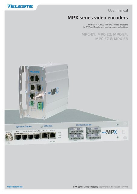
MPC series video encoders mechanical connections1. <strong>Video</strong> input(s) connector (BNC female) and indicator leds.2. Contact closure interfaces (4-pin screw terminal).*3. Led indicators. See tables below for detailed description.4. Power supply connector (2-pin screw terminal, +12 VDC).5. Management connection (CLI) (RJ-45 female).6. Fast Ethernet up-link interface (port A). Either electrical (RJ-45 female)or optical (LC).7. Data interfaces, EIA RS232/422/485 (RJ-45 female).8. Audio line connection (RJ-45 female).9. Fast Ethernet interface (port B), fi xed (RJ-45 female).** optionalLed Colour ModeTGreenBlinking greenYellowDarkPort confi guredOn streamLink missingPort not confi guredT - (terminal server) Led indicator operation.Led Colour ModeLGreenYellowDarkLink OKLink missing or level too lowNot in useL - (Ethernet network link) led indicator operationOnly A-port up and confi gured:- Green when A-port has cable connected- Yellow when A-port has not cable (B-port doesn’t affect)Only B-port up and confi gured:- Green when B-port has cable connected- Yellow when B-port has not cable (A-port doesn’t affect)Both A- and B- ports up and confi gured:- Green when both A- and B-ports has cable connected- Yellow when either of the cables is disconnectedLed Colour ModeMGreenBlinking greenRedPower ONDevice is being confi gured from the webinterfaceHardware errorM - (module) Led indicator operation.<strong>MPX</strong> series video encoders user manual 3
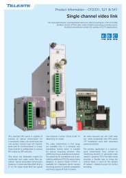
TL<strong>MPX</strong> <strong>Series</strong> <strong>Video</strong> <strong>Encoders</strong> <strong>Front</strong> <strong>Panel</strong><strong>MPX</strong>-E8 combinationsContact ClosureAudio1 23 43 47 8781 25 6M6MTLContact ClosureInput Output76MEthernetPort APort BTx Rx54EthernetTPort AL6Port BTx Rx54EthernetPort APort BTx Rx54Terminal Server<strong>Video</strong> Encoder<strong>Video</strong> 1 <strong>Video</strong> 2 <strong>Video</strong> 3 <strong>Video</strong> 4 <strong>Video</strong> 5 <strong>Video</strong> 6 <strong>Video</strong> 7 <strong>Video</strong> 8 Data 1 Data 2 Data 3 Mgmt321Vx8 Dx3 Ax8 C C x4 Ex2Terminal Server<strong>Video</strong> Encoder<strong>Video</strong> 1 <strong>Video</strong> 2 <strong>Video</strong> 3 <strong>Video</strong> 4 <strong>Video</strong> 5 <strong>Video</strong> 6 <strong>Video</strong> 7 <strong>Video</strong> 8 Data 1 Data 2 Data 3 Audio/Mgmt321Vx8 Dx3 Ax2 C C x8 Ex2Terminal Server<strong>Video</strong> Encoder<strong>Video</strong> 1 <strong>Video</strong> 2 <strong>Video</strong> 3 <strong>Video</strong> 4 <strong>Video</strong> 5 <strong>Video</strong> 6 <strong>Video</strong> 7 <strong>Video</strong> 8 Data 1 Data 2 Data 3 Audio/Mgmt321Vx8 Dx3 Ax2 Ex24 <strong>MPX</strong> series video encoders user manual
<strong>MPX</strong> series video encoders mechanical connections1. <strong>Video</strong> input(s) connector (BNC female) and indicator leds.2. Data interfaces, EIA RS232/422/485 (RJ-45 female).3. Management connection (CLI) (RJ-45 female) andAudio line connection, two channel (RJ-45 female).4. Fast Ethernet interface (port B), fi xed (RJ-45 female).5. Fast Ethernet up-link interface (port A). Either electrical (RJ-45 female)or optical (LC).*6. Led indicators. See tables below for detailed description.7. Contact closure interfaces (8-pin screw terminal).*8. Audio line connection, eight channel (RJ-45 female).** optionalLed Colour ModeTGreenBlinking greenYellowDarkPort confi guredOn streamLink missingPort not confi guredT - (terminal server) Led indicator operation.Led Colour ModeLGreenYellowDarkLink OKLink missing or level too lowNot in useL - (Ethernet network link) led indicator operationOnly A-port up and confi gured:- Green when A-port has cable connected- Yellow when A-port has not cable (B-port doesn’t affect)Only B-port up and confi gured:- Green when B-port has cable connected- Yellow when B-port has not cable (A-port doesn’t affect)Both A- and B- ports up and confi gured:- Green when both A- and B-ports has cable connected- Yellow when either of the cables is disconnectedLed Colour ModeMGreenBlinking greenRedPower ONDevice is being confi gured from the webinterfaceHardware errorM - (module) Led indicator operation.<strong>MPX</strong> series video encoders user manual 5
InstallationQuick instructions1234567Install the temperature hardened stand-alone <strong>MPX</strong> encoder device to theinstallation location. A +12 V supply voltage is provided by a CPS25xseries power supply (see example picture bottom).Switch on the system power and wait a until the “L” and “M”- indicatorson the front panel of the device are lit. The “M” (=module) should litgreen to show that hardware is operating properly.Connect all needed data/audio signals to their respective connectors onthe device’s front panel.Connect a CVBS video signals to the BNC female connectorson the device.Connect the Ethernet 100Base-TX/FX network to “Fast Ethernet”connector on the device’s front panel.Note! A local WebUI connection can be created by this connectorusing an Ethernet cable such as <strong>Teleste</strong> OPUS1CAA0300X crossconnection cable (when CAT-5 interface).Create management connection to the device either over an Ethernetnetwork or from a Mgmt port and then set all necessary settings in thedevice. Factory default settings for the device are the following:10.9.96.10 (IP, eth0, Ethernet port A)255.255.255.0 (Netmask, eth0, Ethernet port A)10.9.96.1 (Gateway)Make sure that the device is not indicating any alarms or warnings.The “L” and “M” - indicators on the front panel should now lit green.Note! If the “M” indicator is red, the device in question has ahardware error and service is needed.CPS25x series power supply for MPC device.CPS25x series power supply for <strong>MPX</strong> device.6 <strong>MPX</strong> series video encoders user manual
ConnectionsGeneralAll products in the <strong>MPX</strong> family have the same connection scheme intheir connectors. Depending on the model, there are <strong>Video</strong>, Data,Audio, Contact closure, Mgmt & Ethernet connections.<strong>Video</strong> connectionsNote! Alternatively the video inputimpedance can be set to high mode(MPC-EZ and MPC-E1 HW versionG onwards).The video connector type is a BNC female. The video input impedanceis 75 Ω. The nominal input level is 1 Vpp. <strong>Video</strong> inputs are wequippedwith dual colour VIDEO indicator led’s on the front panel. <strong>Video</strong> portsettings can be confi gured from web user interface (WebUI).Led Colour <strong>Video</strong> mode<strong>Video</strong>GreenYellowDarkPort confi gured and video OKPort confi gured and no videoPort not confi gured<strong>Video</strong> indicator led operation.Data connectionsAll data connectors provide one bi-directional data channel. Data portsettings can be confi gured from web user interface (WebUI). Supporteddata types are RS232, RS422, RS485-2w and RS485-4w.A recommended cable for data connection is <strong>Teleste</strong> CIC603.MPC dataconnectors (2 xRJ-45 female).<strong>MPX</strong> dataconnectors (3 xRJ-45 female).PinColour1 White / green stripe2 Green3 White / orange stripe4 Blue5 White / blue stripe6 Orange7 White / brown stripe8 BrownCIC603 cable’s pinout / wire colors(RJ-45 male / open wires).Pin RS232 RS422 RS485-2w RS485-4w1 out + in / out + out +2 out out - in / out - out -3 in - in / out - in -45 Ground Ground Ground Ground6 in in + in / out + in +78 Ground Ground Ground GroundData connector’s pinout and supported data types.RS232 is an unbalanced data format (i.e. the signal wire workingagainst a reference – ground). Simplex RS232 requires two connections(signal and ground). Full-duplex RS232 requires three connections(signal TX, signal RX and ground).<strong>MPX</strong> series video encoders user manual 7
RS422 is a balanced data format. Simplex RS422 requires three dataconnections (+/- and ground). Full-duplex RS422 requires fi ve dataconnections (in+/in-, out+/out- and ground).RS485 is used for full-multipoint communications where multipletransceiver devices may be connected to a single twisted-pair signalcable. Most RS485 systems use a Master/Slave architecture, whereeach Slave unit has a unique address and responds only to packetsaddressed to that unit. Packets are generated by the Master (e.g. CCTVcontroller keyboard), which periodically ‘polls’ all connected Slave units(e.g. CCTV camera receiver units). The Slave unit that has beenaddressed then sends the appropriate reply packet back to the Master.Slave units have no means of initiating communication without the riskof a collision so they need to be assigned the ‘right to transmit’ by theMaster (by polling). RS485 exists in two versions, 2-wire and 4-wire.MasterDecoderEncoderSlave+Pin 1++Pin 1+Tx / RxTxTxTx / Rx-Pin 2--Pin 2-EthernetPin 3--Pin 3RxRxPin 6++Pin 6GNDPin 5Pin 8Pin 5Pin 8GNDRS485-2w data connection diagram.A 2-wire RS485 network is implemented as a half-duplex system usingsingle twisted-pair cabling. This means that data can fl ow in bothdirections but only in one direction at a time.Note! Wiring for the 2-wire mode needs to be done externallyon the connector.MasterDecoderEncoderSlave+Pin 1++Pin 1+TxTxTxTx-Pin 2--Pin 2-Ethernet-Pin 3--Pin 3-RxRxRxRx+Pin 6++Pin 6+GNDPin 5Pin 8Pin 5Pin 8GNDRS422 / RS485-4w data connection diagram.A 4-wire RS485 network can be implemented as a full-duplex systemusing two twisted-pair buses where each bus is used for each directionof transmission.8 <strong>MPX</strong> series video encoders user manual
Data termination and biasingThe hardware support for RS-data line termination and biasing isavailable from version F onwards for all MPC encoders/decoders and<strong>MPX</strong> E8 encoders. The <strong>MPX</strong> D8 decoder does not have this support.Termination is used to match impedance of a node to the impedance ofthe transmission line being used. When impedance are mismatched, thetransmitted signal is not completely absorbed by the load and a portionis refl ected back into the transmission line. If the source, transmissionline and load impedance are equal these refl ections are eliminated.Biasing -> the lines will be biased to known voltages and nodes will notinterpret the noise from undriven lines as actual data; without biasingresistors, the data lines fl oat in such a way that electrical noisesensitivity is greatest when all device stations are silent or unpowered.RS4852-wireLineTerminationLineBiasing+5VRx+-120Ω680Ω680ΩPin 6Pin 3Tx-+Pin 2Pin 1Data modeRS232RS422RS485 - 2wRS485 - 4wInput termination optionsNoneNo term (with failsafe)Line termination (120 Ω)No term (with failsafe)Hard bias (forced 680 Ω line biasing)Line termination (120 Ω)No term (with failsafe)Hard bias (forced 680 Ω line biasing)Line termination (120 Ω)Data input termination options for data channels. Data termination connects 120Ω between pins. Hard bias connects 680 Ω (+input) to +5V and GND (- input).<strong>MPX</strong> series video encoders user manual 9
Audio connection (MPC/<strong>MPX</strong> two/four audio channel models)Audio connector, two audio channelMPC/<strong>MPX</strong> models (1 x RJ-45 female).The Audio connector(s) provides two bi-directional audio channels,which can be used for one stereo audio or two mono audio purposes.The audio interface supports unbalanced wiring. The audio impedanceis constant and cannot be adjusted. The audio input impedance is >10kΩ and the output impedance is 10 kΩ). Alternatively the audio input impedance can be setto 600 Ω (this setting requires balanced wiring for both channels). Theaudio output impedance is set to 10 Ω. The audio channels operatesindependently, i.e. despite the absence of all video signals.Pin Balanced signal Unbalanced signalAudio connectors, eight audio channel<strong>MPX</strong> models (4 x RJ-45 female).1 Audio 1 out - GND2 Audio 1 out + Audio 1 out3 Audio 2 out - GND4 Audio 2 in + Audio 2 in5 Audio 2 in - GND6 Audio 2 out + Audio 2 out7 Audio 1 in - GND8 Audio 1 in + Audio 1 inAudio connector’s pinout (eight audio channel models). A recommendedaudio cable is <strong>Teleste</strong> CIC603.Note! RJ-45 connector’s shield is grounded.10 <strong>MPX</strong> series video encoders user manual
Mgmt connectionMgmt connector (RJ-45 female).PinCCIN+ IN-CC inputor+ -TTLlevel voltageSignal1 Ground2 Mgmt out3 Ground456 Mgmt in78Mgmt connector’s pinout. Arecommended management cable is<strong>Teleste</strong> CIC504.CCIN+ IN-ShortcircuitContact closure connections.CC outputCCOUTRelay on/off(24V / 1A)The Mgmt (Management) connector provides one bi-directional(RS232) data channel. The Mgmt connection is for local confi gurationand control of <strong>MPX</strong> series encoders. The command line interface (CLI)is intended for administration use, and can be accessed locally usingserial terminal program or remotely using telnet program. Typical use ofthe CLI is to set up the IP address for the encoder, update the encoder’ssoftware and for remote diagnostics.PC/PSION D9 female RJ-45 male <strong>MPX</strong> encoderReceive data 2 2 Mgmt outputTransmit data 3 6 Mgmt inputSystem ground 5 1 GroundManagement cable (CIC504) pinout (D9 female / RJ-45 male).Contact closure loop (CCL) connection (optional)The MPC series video encoders provides optionally 1 or 3 bi-directionalcontact closure channel lines. The <strong>MPX</strong> series video encoders providesoptionally 4 or 8 bi-directional contact closure channel lines.There are optionally two different CC input connection ways, one for anormal short circuit (dry contact closure) on / off - input signals betweenconnector’s contact pins (internal power source) and one for TTL levelvoltage input signals (data rate max 5 Hz, sink current 20 mA at 5V DC)between contact pins (external power source). CC output is a normalrelay on/off - output signal (24V / 1A) between connector’s contact pins.Depending on the model, the CCL connector type is a 4 or 8 - pinscrew terminal.<strong>MPX</strong> series video encoders user manual 11
Ethernet connectionsEthernet connector (CAT5).Pin Signal1 Tx +2 Tx -3 Rx +456 Rx -78Ethernet connector’s pinout (CAT5).The Fast Ethernet Port A (eth0) interface is 10/100Base-TX or100Base-FX Ethernet network interface. The connector type is either aRJ-45 female (when electrical) or LC (when optical). The 100Base-FXFast Ethernet Port A interface is a small form-factor pluggable (SFP).The Fast Ethernet Port B (eth1) interface is a fi xed 10/100Base-TXEthernet interface. The connector type is a RJ-45 female.Led Colour Ethernet mode21OrangeBlinking orangeDarkYellowDarkLink upOn streamReceiving data100 Mbps10 MbpsEthernet port’s (A & B) led indicator operation.Fibre connectionThe optical Ethernet up-link interface is a small form-factor pluggable(SFP). The small form-factor pluggable is a specifi cation for a newgeneration of optical modular transceivers. The optical output level isconstant and cannot be adjusted.When installing the fi bre optic cable, do not exceed the minimumbending radius when connecting cable to the system.2 fibre version 1 fibre versionTx Rx Tx/RxSFP plug-in optical transceiver module.Note! For correct optical operation ensure that all optical connectorsare cleaned immediately before mating. Connectors shouldalways be cleaned using high purity alcohol (e.g. methyl orisopropyl alcohol). Dry the surfaces using clean compressed airor other equivalent pressurised gas. The optical connectors onthe equipment should always be protected with dustcaps whenthere is no fi bre inserted.Optical Ethernet connection meets class 1 laser safety requirements ofIEC 60825-2: 2004 and US department of health services 21 CFR1040.10 and 1040.11 (1990) when operated within the specifi edtemperature, power supply and duty cycle ranges.INVISIBLE LASERRADIATIONOptical connector is the type of LC.CLASS 112 <strong>MPX</strong> series video encoders user manual
How to unplug or plug-in the SFP transceiver moduleIf your up-link port requirements change, simply unplug the existing SFPmodule, and plug-in the new module. The SFP transceiver modulesmust be installed before the encoder is powered on.The SFP transceiver module has a bale-clasp latch that makes easier toinstall or remove the module. Protect the SFP module by inserting aclean dustplug into the module after you remove the fi ber cable. Be sureto clean the optic surfaces of the fi ber cable before you plug the cableinto another module. When using 2 fi bre version SFP, check whichconnector plug is send (Tx) and which is receive (Rx) .Bail clasplatchhinge pinSFP module’s locking release points.To unplug and plug-in the SFP module, follow these steps1. Open the bale clasp on the SFP module by pressing the claspdownward until it is in a horizontal position.2. Use a small fl at-blade screwdriver or other long, narrow instrument topush on the hinge pin to unlock the SFP cage latch.3. Grasp the SFP module by the bale clasp and gently pull it out of theSFP cage.To plug-in the module:4. Orient the transceiver with the bale clasp on the bottom, close thebale clasp by pushing it up over the transceiver, then gently insertthe transceiver into the port until it clicks into place.<strong>MPX</strong> series video encoders user manual 13
<strong>Video</strong> streaming<strong>Video</strong> 1MPUMPC-E1 contains one video input andone media processing unit (MPU).<strong>Video</strong> 1MPU1<strong>Video</strong> streaming methodsBlock diagrams on the left side describe the way how <strong>MPX</strong> seriesencoder physical video input(s) are internally connected to MPU(s).<strong>Video</strong> input is the physical video connector (BCN female) available forCVBS signal. MPU is a part of <strong>MPX</strong> series encoder’s hardware whosemission is to process media (video, audio, pictures). Naturally each videoinput can be connected to a camera or any other standard PAL or NTSCvideo source.<strong>Video</strong> 2MPU2Encoding profileMPC-EZ contains two video inputs andtwo media processing units (MPUs).<strong>Video</strong> 1<strong>Video</strong> 2<strong>Video</strong> 1<strong>Video</strong> 2<strong>Video</strong> 3<strong>Video</strong> 4MPUMPC-E2 contains two video inputs andone media processing unit (MPU).MPU1MPU2MPC-E4 contains four video inputs andtwo media processing units (MPUs).<strong>Video</strong> 1<strong>Video</strong> 2<strong>Video</strong> 3<strong>Video</strong> 4<strong>Video</strong> 5<strong>Video</strong> 6<strong>Video</strong> 7<strong>Video</strong> 8MPU1MPU2MPU3MPU4<strong>MPX</strong>-E8 contains eight video inputs andfour media processing units (MPUs).Note! A single MPU can not encode allMPEG-4, MJPEG and MPEG-2 videostandards simultaneously.<strong>MPX</strong> series encoders has a total of four encoding profi les available forvideo inputs that are connected to one MPU. Inputs in this context meaninputs that are hardware connected to one MPU. Each encoding profi lecan be set separately for individual resolution, frame rate, GOPstructure and I/P-frame complexity, within the calculation power of theMPU. In case of full resolution and full frame rate video, such as D1 and4CIF, one profi le takes almost the full capacity of one MPU.<strong>Video</strong> inputMPUPicture uploadServer directory URLConnectionDestination IP addressStream multiplicationJPEGimage capturePrimarystreamAdditional destination IP addressAdditional destination IP addressAdditional destination IP addressAdditional destination IP addressThis block diagram describes single encoding profi le max. performance.<strong>Video</strong> MPC-E1 MPC-E2 MPC-E4 MPC-EZ <strong>MPX</strong>-E8Inputs (video connectors) 1 2 4 2 8Encoding profi les 4 4 8 8 16Output streams (total) 20 20 40 40 80JPEG captures 4 4 8 8 16Available video streaming performance for <strong>MPX</strong> series encoders.Note! <strong>MPX</strong> series encoders video streaming performance couldoverload Fast Ethernet throughput depending on number ofstreams/bitrate combination. Be sure that the confi guration doesnot exceed Fast Ethernet port throughput. E.g. as an example:MPC-E4 number of encoded streams 30, bitrate 4000 kbps = 120Mbps -> Fast Ethernet throughput is exceeded.additional streams14 <strong>MPX</strong> series video encoders user manual
<strong>Video</strong> stream multiplicationEach video encoding profi le can be assigned with fi ve (5) differentdestination addresses (primary stream and additional streams). Theseaddresses can be freely set to unicast, multicast or a combination ofthese. In addition there is a tick box that enables to fi lter out P-frames fromeach output stream for low frame rate applications. This approachprovides for a very cost effi cient dual streaming in situations where the lowframe rate stream is a direct subset of the higher frame rate stream. Inpractise this means that the number of I-frames is the common nominator.As an example, one MPC-E4 unit can stream (unicast or multicast) 4 x2CIF@25fps for monitoring and 4 x 2CIF@3fps (unicast or multicast) forrecording simultaneously. The precondition of this is that the number ofI-frames per second in the primary stream is confi gured with I-frameinterval setting to match the frame rate of the low fps stream. In theexample above the I-frame interval of the primary stream would need tobe 8 (GOP = IPPPPPPPIPPPPPPPIPP…) generating 3 I-frames persecond thus resulting in 3fps stream when P-frames are fi ltered out.The use of multiple destination addresses up to a certain degree doesn’tload the MPU; however one should take into account that the aggregatebit rate of all output streams does not exceed the capacity of the100Mbps interface.JPEG image captureAdditionally there is a JPEG image capture feature that allows takingJPEG snapshots from the video and storing them into a ftp server. It isalso possible view JPEG captures with http. There are four JPEGcapture channels available for each MPU. See pages 32-35 how toconfi gure JPEG image captures (i.e. picture upload settings).<strong>MPX</strong> series video encoders user manual 15
How to change the settingsGeneralThis chapter tells how you can confi gure and check the settings of <strong>MPX</strong>series video encoders with the help of web user interface (WebUI) orcommand line interface (CLI).Web user interface (WebUI)<strong>Teleste</strong>’s WebUI provides an user friendly way to confi gure and manage<strong>MPX</strong> series video encoders. WebUI can be accessed using Internetbrowser such as Internet Explorer.Command line interface (CLI)<strong>Teleste</strong>’s <strong>MPX</strong> series video encoders include also a text-based userinterface (CLI) for confi guration purposes. CLI is accessed through anyterminal emulator application, locally using serial connection (e.g. HyperTerminal) or remotely using TCP/IP (e.g. PuTTY).User groupsThere are different user levels, which are determined by the usernameand password. The username and password can be change via theWebUI and CLI.User group Username Password AuthorityAdministrator admin easixRead and write access toall pages and all settingsOperators - - Read-only accessUser groups for WebUI and CLI.Note! See section user management, page 38.Factory resetThe factory reset can be done via CLI with eraseconf command (seepage 63), or enabling interactive mode while rebooting/starting thedevice (requires connection through management port locally).Note! CLI’s eraseconf command doesn’t clear IP confi guration.How to enable the interactive mode:1. Connect to the device via management port (as local CLI connectionmethod), see page 562. Reboot the switch3. While the switch is restarting, press Ctrl-C when the “Press Ctrl-Cnow to activate interactive mode” text appears on the screen4. Select the required mode (enter letter and press enter):• f - clears all confi guration (including IP-confi guration)• c - clears confi guration (all execpt IP-confi guration)16 <strong>MPX</strong> series video encoders user manual
Web user interface (WebUI)GeneralThe <strong>MPX</strong> series video encoders can be fully controlled using Web userinterface (WebUI). You can access the Web user interface either locallyusing Ethenet crossover cable such as <strong>Teleste</strong> OPUS1CAA0300X(when CAT-5 interface) or remotely over the Ethernet connection.System requirements for WebUI* PC equipped with an Ethernet Network card and an Internetbrowser installed* Cross-connected Ethernet cable (e.g. type OPUS1CAA0300X)OperationWeb user interface window consists of several pages. Only one page isvisible at the time. You can activate a page simply by clicking the page’sheading (see picture below).The Web user interface has the following confi guration display pagesthat are introduced in this document:The information on confi guration pages is shown in data fi elds or boxes.The settings can be changed in the data fi elds and boxes having whitebackground. Place the cursor in the desired data fi eld or box and entera new setting. Some settings are entered by ticking a checkbox orclicking on a radio button, by selecting from a pull-down list or byscrolling digits with the help of spin buttons.Information without datafi eld or box is a read only parameter and cannotbe changed.Press keyboard’s F5 button to refresh the WebUI page view.When changing the settings, always click OK buttonto confi rm settings.<strong>MPX</strong> series video encoders WebUI user manual 17
StartingTo create a WebUI session to the device, fi rst enter the device IPaddress into the web browser’s address bar, i.e. 172.31.6.9. The followingWeb user interface’s MAIN PAGE will appear on the screen. Writethe required username and password (see bottom) in the fi elds and thenclickbutton to continue --> Web user interface’s MAIN PAGEappears on the screen (see picture above). <strong>Front</strong> panel M-led blinks forsuccessful login.The Web user interface session to <strong>MPX</strong> series video encoders isnow active.Note! User can logout either by selecting Logout from menu baror by closing the browser. WebUI session can also automaticallyexpire and logout within 60 minutes if no activity.admineasixNote! <strong>MPX</strong> series video encoders default factory IP addressis 10.9.96.1018 <strong>MPX</strong> series video encoders WebUI user manual
Logged in as:Host:Type:Serial Number:HW Version:SW Version:Uptime:Current time:Extra:Product:Device Status:MAIN PAGEThe MAIN PAGE is opened after the WebUI session has beenestablished to the <strong>MPX</strong> series video encoder. This page shows device’scurrent properties and alerts.User’s authority classAlias name for the device (uniquely identifi es each device in the network)and it’s IP addressPROPERTIESDevice type (part number)Device serial numberDevice hardware versionDevice fi rmware versionDevice uptimeDevice current timeADDITIONAL INFORMATIONTimestamp for the release of fi rmwareFirmware type (e.g. in encoders <strong>MPX</strong>-E and in decoders <strong>MPX</strong>-D)ALERTSShows device’s current status. The colour bar change color to refl ect thestatus of the device. Green colour bar with Ok text indicates that there isno alert(s). Yellow colour bar with text indicates that there is alert(s).<strong>MPX</strong> series video encoders WebUI user manual 19
When monitoring an area for security, there may becertain parts within the camera’s fi eld of view thatneed to be kept private. Masking is a feature thatenables these areas to be concealed from view.Input:Status:Brightness:Contrast:Saturation:Colour mode:Impedance:Masking:VIDEO INPUT SETTINGSClick “<strong>Video</strong> Inputs” menu under the Confi guration heading. <strong>Video</strong> inputsettings page appears on the screen. This page shows device’s videoinput settings.PROPERTIESAlias name for the video inputShows video status. The colour bar change color to refl ect the status ofthe video. Green colour bar means that there is no alert(s). Yellowcolour bar with text tells that there is alert(s).Brightness value for the video channelContrast value for the video channelSaturation value for the video channelColour mode for video inputImpedance for video inputShows masking status20 <strong>MPX</strong> series video encoders WebUI user manual
Masking settings can bechanged by clicking this linkInput:Brightness:Contrast:Saturation:Colour Mode:Impedance:Masking:Masking Mode:Mask Editor:VIDEO INPUT SETTINGS - MODIFYClick “Edit <strong>Video</strong> Inputs” menu under the Confi guration heading. <strong>Video</strong>input settings page appears on the screen. This page shows device’svideo input settings.PROPERTIESAlias name for the video inputBrightness value for the video channel (+/-50%]Contrast value for the video channel (+/-50%)Saturation value for the video channel (+/-100%)The colour mode for each video input can be set to match with the typeof camera connected:- Auto: Day and Night camera- Colour: Colour camera- B&W: Black & White cameraNote! With some day/night camera models the transition betweenB&W and colour mode is not always correctly detected. In thiscase it is recommended to set the Colour Mode manually toColour or B&W.Not in useWhen monitoring an area for security, there may be certain parts withinthe camera’s fi eld of view that need to be kept private. Masking is afeature that enables these areas to be concealed from view.Normal or fully masked. In the normal mode masking area is adjustablewith mask editor and in the fully masked mode whole area is masked(darken picture)Opens the mask editor window, where the user can confi gure theencoder to automatically hide certain areas with a mask, which can beadjusted in terms of its colour.<strong>MPX</strong> series video encoders WebUI user manual 21
Painted area is chosen for watching.Refresh video:Painting mode:Masking mode:Brush size:Mask colour:VIDEO INPUT SETTINGS - MODIFYClick Mask Editor menu under the VIDEO INPUT SETTINGS - MODIFYheading. Mask editor page appears on the screen. User can confi gure theencoder to automatically hide certain areas with a mask, which can beadjusted in terms of its colour.MASK EDITOR - VIDEO INPUT 1MASK EDITOR page contains settings for hiding certain areas from theencoded picture.EDIT TOOLSEnables/disables automatic video refreshingPainting mode adds area for watching --> highlights areaMasking mode removes area for watching --> hides areaSelect brush size for masking (x 1/2/3/4)Select brush colour for masking (gray/red/green/blue)22 <strong>MPX</strong> series video encoders WebUI user manual
Device video encoding settingscan be changed by clicking this linkLink To SDP fi le (Session Description Protocol). The SDPfi le contains stream parameters that are meant for 3rd partyapplications (e.g. SW decoders) to open/view the stream.<strong>Video</strong> standard:Input:Stream name:Status:Destination IP address:UDP port:Resolution: (*MJPEG only)Bitrate:Framerate:VIDEO ENCODING SETTINGSClick “<strong>Video</strong>” menu under the Confi guration heading. Depending on thecofi guration, either MPEG4, MJPEG or MJPEG2 encoding settings pageappears on the screen. This page shows device’s video encoding settings.<strong>Video</strong> standard type (PAL or NTSC), can be change from COMMONSETTINGS - MODIFY pageActive video input(s)User defi nable alias name for the video input<strong>Video</strong> status, either active or no signalMulticast: Multicast IP address / multicast groupUnicast: IP address of receiving decoderUDP port number<strong>Video</strong> resolution, either QCIF/CIF/2CIF/4CIFad/4CIF/4CIFpi* or D1Encoded video bitrate, 9.6 Kbps...8 Mbps (MPEG-4/MJPEG/MPEG-2)Encoded video framerate, 1...30 fps (MPEG-4/MJPEG/MPEG-2)Edit <strong>Video</strong> Encoding Settings:Opens video encoding settings pageResolution PAL NTSC Framerate Interlaced NoteD1 720 x 576 720 x 480 25 PAL, 30 NTSC YesHALF D1 352 x 576 352 x 480 25 PAL, 30 NTSC Yes4CIFad 704 x 576 704 x 480 1...25 PAL, 1...30 NTSC Yes4CIF 704 x 576 704 x 480 1...25 PAL, 1...30 NTSC No4CIFpi 704 x 576 704 x 480 1...25 PAL, 1...30 NTSC Yes MJPEG only2CIF 704 x 288 704 x 240 1...25 PAL, 1...30 NTSC NoCIF 352 x 288 352 x 240 1...25 PAL, 1...30 NTSC NoQCIF 176 x 144 176 x 112 1...25 PAL, 1...30 NTSC NoAvailable video resolutions.<strong>MPX</strong> series video encoders WebUI user manual 23
QP (QuantizationParameter) 1 to 31.1 means best quality andhigher bit-rate requirement,31 means low picturequality and lower bit-raterequirement.VIDEO ENCODING SETTINGS - MODIFY4CIF resolutions4CIF - This mode takes oneof the fields from theinterlaced video source andscales it up into 4CIF imagebefore the encoding takesplace. This mode isintended to be shown inprogressive monitor.4CIFad - This modecombines odd and evenfi elds from the interlacedvideo source with motionadaptive de-interlace fi lter.This is optimum mode forprogressive monitor.4CIFpi - This mode is anequivalent to D1 except forthe resolution. It combinesodd and even fi elds from theinterlaced video sourcewithout any advancedprocessing. This is optimummode for decoder feedinganalogue monitor. In case ofprogressive monitor, theproper decoding of thismode requires the use ofde-interlacing fi lter in theSW decoder.Click “Edit video encoding settings” menu under the VIDEO ENCODINGSETTINGS heading. <strong>Video</strong> encoding settings - modify / Common pageappears on the screen. Device video common settings can be changed onthis page.VIDEO SETTINGS - MODIFY pages (Common, Connection, StreamMultiplication, Advanced, <strong>Video</strong> Overlay Position and <strong>Video</strong> OverlayContent) contain one (MPC-E1/E2) or two (MPC-E4) or four (<strong>MPX</strong>-E8)MEDIA PROCESSING UNIT (MPU) blocks. Each MPU contains fourseparated encoding profi les which can be individually confi gured.MEDIA PROCESSING UNITInput: Enable/disable video inputName: User defi nable alias name for the video input (max 16 chars)Active: Active/inactive video inputResolution: <strong>Video</strong> resolution, either QCIF/CIF/2CIF/4CIFpi/4CIF/4CIFpi/half D1 or D1.The processing bar next to MEDIA PROCESSING UNIT 1...4 header informencoding capacity of the device. The processing bar colour must be green,if the processing bar goes to red, the resolution settings are not acceptableBitrate mode: Encoded video bitrate mode, either CBR (1...8192 kbps), VBR or VBRcapped (1...31 QP / 0...100%). The capped value defi nes the maximumallowed bit-rateBitrate: Encoded video bitrate;MPEG-4 / MJPEG: 9.6 Kbps...8 Mbps, MPEG-2: 128 Kbps...8 MbpsFramerate: Encoded video framerate;MPEG-4 and MJPEG: 1...25 for PAL, 1...30 for NTSCMPEG-2:25 for PAL, 30 for NTSCNote! have to be integer value24 <strong>MPX</strong> series video encoders WebUI user manual
VIDEO ENCODING SETTINGS - MODIFYRTCP note:RTP is used in conjunctionwith the RTP Control Protocol(RTCP). While RTP carriesthe media streams (e.g.,audio and video), RTCP isused to monitor transmissionstatistics and aidssynchronization of multiplestreams. When bothprotocols are used inconjunction, RTP isoriginated and received oneven port numbers and theassociated RTCPcommunication uses the nexthigher odd port number. Ifport numbers are configureddifferently, then unexpectedproblems may occur indecoding. RTCP designed tosynchronize the video andaudio timestamps accordingto NTP time when theytransfer over RTP.For instance :6006 <strong>Video</strong> RTP6007 <strong>Video</strong> RTCP6008 Audio 32k RTP6009 Audio RTCPDestination IP address:UDP port:DSCP:P-Frame Filter:Click “Connection” menu under the VIDEO ENCODINGSETTINGS - MODIFY heading. <strong>Video</strong> encoding settings -modify / connection page appears on the screen. Devicevideo connection settings can be changed on this page.MEDIA PROCESSING UNITMulticast: Multicast IP address / multicast group.This multicast IP address has to be same at both encoder andcorresponging decodersNote! Gateway address is necessary for multicasting.Device IP and gateway addresses must be in the samenetwork. The Gateway address must be set before enablingmulticast.Unicast: IP address of receiving decoderUDP port number (0...65535). This number has to be sameat both encoder and decoder pairsNote! Although both even and odd UDP port numbersare supported, it is recommended to use even portnumbers to ensure compatibility with some of thestandard software decoders.(Defi nition of the Differentiated Services) fi eld lets you set bitsin the stream IP header allowing a network device to applyrules such as how the packet is forwarded in the network andQoS (Quality of service) management.Enable/disable to fi lter out P-frames from selected outputstream for low frame rate applications.Note! P-Filter is not possible for interlased video, suchas D1 or Half D1.<strong>MPX</strong> series video encoders WebUI user manual 25
VIDEO ENCODING SETTINGS - MODIFYAdditional Destination IP Address:Additional UDP Port:DSCP:P-Frame Filter:Click “Stream Multiplication” menu under the VIDEO ENCODINGSETTINGS - MODIFY heading. Vide settings modify / streammultiplication page appears on the screen.Device video stream multiplication settings can be changed on this page.MEDIA PROCESSING UNITThese addresses can be freely set to unicast, multicast or a combinationof theseAdditional UDP port number (0...65535). This number has to be same atboth encoder and corresponging decoders(Defi nition of the Differentiated Services) fi eld lets you set bits in the streamIP header allowing a network device to apply rules such as how the packetis forwarded in the network and QoS (Quality of service) management.Enable/disable to fi lter out P-frames from selected output stream for lowframe rate applications.Note! P-Filter is not possible for interlased video, such as D1 orHalf D1.26 <strong>MPX</strong> series video encoders WebUI user manual
VIDEO ENCODING SETTINGS - MODIFYIntraframe period:I/P Frame Size (CBR):GOP Format:Click “Advanced” menu under the VIDEO ENCODING SETTINGS -MODIFY heading. <strong>Video</strong> settings modify / advanced page appears on thescreen. Device video advanced settings can be changed on this page.MEDIA PROCESSING UNITThis value, PAL (1..50), NTSC (1..60), indicates the I-frame interval withregards to the defi ned frame rate setting. A value of n will result inI-frame being generated every n th frame, i.e.n = 1 --> GOP = IIIIII....n = 2 --> GOP = IPIPIP....n = 3 --> GOP = IPPIPPIPP...Consequently the number of I-frames per second is dictated by theframe rate setting. With e.g. n=3 the result is following:Frame rate = 25 --> 8 I-frame per secondFrame rate = 3 --> 1 I-frame per secondI/P frame size (100...1000 %). Used only in CBR mode. This valueprovides the I-frame/P-frame size ratio (how much bigger I-frames arethan P-frames in per cents). Some example values present bottom.MPEG-2 GOP format, selectable I, IP, IBP, IBBPDefault valueParametervalue %SizeratioExplanation100 1 I-frames are the same size than P-frames250 2.5 I-frames are 2,5 times bigger size than P-frames500 5 I-frames are 5 times bigger size than P-frames<strong>MPX</strong> series video encoders WebUI user manual 27
VIDEO ENCODING SETTINGS - MODIFYVertical Position:Horizontal Position:Margin:Horizontal Aligment:Font Size:<strong>Video</strong> overlay is a technique used to display a text over on a video.Click “<strong>Video</strong> Overlay Position” menu under the VIDEO ENCODINGSETTINGS - MODIFY heading. <strong>Video</strong> settings modify / video overlayposition page appears on the screen. Device video overlay position settingscan be changed on this page, i.e. what is text position on the screen.MEDIA PROCESSING UNITText position, either top, center or bottom of screenText position, either left, center or right of screenText top margin (0...100 %)Text aligment, either auto, left, center or rightText font size (1...30)28 <strong>MPX</strong> series video encoders WebUI user manual
VIDEO ENCODING SETTINGS - MODIFYPre Text:Timestamp1:Timestamp2:Post Text:Click “<strong>Video</strong> Overlay Content” menu under the VIDEO ENCODINGSETTINGS - MODIFY heading. <strong>Video</strong> MPEG4 settings modify / videooverlay content page appears on the screen. Device video overlaycontent settings can be changed on this page, i.e. enter text content andis time and/or date shown or not.MEDIA PROCESSING UNITEnter text before time/data stamp (max 32 chars)Time/date stamp(s)Time/date stamp(s)Enter text after time/data stamp (max 32 chars)<strong>MPX</strong> series video encoders WebUI user manual 29
Link To SDP fi le (Session Description Protocol). The SDP fi le contains stream parametersthat are meant for 3rd party applications (e.g. SW decoders) to open/view the stream.CodecSamplerateConnector/Volume:Name:IP address:Port:Mode:Connector:AUDIO SETTINGSClick “Audio” menu under the Confi guration heading. Audio settingspage appears on the screen. This page shows device’s audio settings.CODEC SETTINGSAudio codec name.Audio codecs samplerate.SOCKET SETTINGSAudio IN Left: Audio volume value (0...100%).Audio IN Right: Audio volume value (0...100%).STREAM SETTINGSUser defi nable alias name for the audio stream.Destination IP address:- Multicast: Multicast IP address / multicast group.- Unicast: IP address of receiving encoder.Note! Gateway address is necessary for multicasting.Device IP and gateway addresses must be in the same network.The Gateway address must be set before enabling multicast.UDP port number.Audio channel mode.Audio connector (Audio in/out).Edit Audio Settings:Opens audio settings page30 <strong>MPX</strong> series video encoders WebUI user manual
CodecSamplerateConnector:AUDIO IN/OUT tickbox:Name:IP address:Port:DSCPMode:Connector:AUDIO SETTINGS - MODIFYClick “Edit Audio Settings” menu under the AUDIO SETTINGSheading. Audio settings modify page appears on the screen. Deviceaudio settings can be changed on this page.CODEC SETTINGSAudio codec.Select one of the available samplerate values (8KHz or 32 KHz).(Setting a higher samplerate value improves audio fi le quality andincreases its size).SOCKET SETTINGSAudio IN Left / Volume: Set a value for audio left volume (0...100%).Audio IN Right / Volume: Set a value for audio right volume (0...100%).STREAM SETTINGSEnable/disable audio channel.User defi nable name/description for the audio stream (max 16 chars).Destination IP address.Multicast: Multicast IP address / multicast group. This multicast IPaddress has to be same at both encoder and corresponging decoders.Unicast: IP address of receiving encoder.UDP port number (0...65535). This number has to be same at bothencoder and decoder pairs.(Defi nition of the Differentiated Services) fi eld lets you set bits in the streamIP header allowing a network device to apply rules such as how the packetis forwarded in the network and QoS (Quality of service) management.Audio channel mode.Audio connector (Audio in/out).<strong>MPX</strong> series video encoders WebUI user manual 31
<strong>Video</strong> standard:Primary Server Directory URL:Secondary Server Directory URL:Input:Active:Status:Resolution:Quality:Update Period:Latest Picture:PICTURE UPLOAD SETTINGSClick “Pictures” menu under the Confi guration heading. Picture uploadsettings page appears on the screen. This page shows device’s pictureupload settings.<strong>Video</strong> standard type (PAL or NTSC), can be change from COMMONSETTINGS - MODIFY pageSERVER SETTINGSPrimary FTP server where the pictures will be uploadedBackup FTP server where the pictures will be uploaded in case thatprimary FTP server failsPicture uploading source (video channel)Active picture uploadsPicture uploading status. The possible values in this fi eld are:-Transmission OK-Transmission failed: The connection with FTP is lost-Error in source fi le reading: There was an error when reading the lastuploaded picture-Disabled-Activated: This messages is shown after activating an previously disabledpicture channelPicture resolution, either QCIF/CIF/2CIF or 4CIF (NTSC or PAL)Picture quality in percentsPicture update periodShow latest picture informationUploaded pictures will be named following the rule:img_mpu00X_chX_YYYYMMDD_HHMMSS.jpeg, where:- mpu00X is the source DSP unit- chx is the souce video channel- YYYYMMDD is the date in format year/month/day- HHMMSS is the time in format hour/minute/second32 <strong>MPX</strong> series video encoders WebUI user manual
%1_%2_%3_%d.%m.%Y_at_%H:%M:%S:%4.jpgFor example: The template %1_%2_%3_%d.%m.%Y_at_%H:%M:%S:%4.jpgwill generate a fi lename --> HostName_mpu002_0_10.06.2009_at_11:55:01:946.jpg%1 The device hostname%2 The MPU ID%3 The channel number in MPU as a decimal (range 0 to 3)%4 The milliseconds as a decimal number (range 000 to 999)Primary Server Directory URL:Secondary Server Directory URL:Input:Active:Filename Template:Enable FTP:Enable HTTP:Resolution:Quality:Update Period:PICTURE UPLOAD SETTINGS - MODIFYClick “Edit Picture Upload Settings” menu under the SERVERSETTINGS heading. Picture upload settings - modify page appears on thescreen. Device picture upload settings can be changed on this page.VIDEO UPLOAD SETTINGS - MODIFY/Common page contains one(MPC-E1/E2) or two (MPC-E4) MEDIA PROCESSING UNIT blocks.Picture upload enables the sending of JPEG snapshots to two different ftpserver directories. Each MPU contains four separated picture uploadingprofi les which can be individually confi gured.SERVER SETTINGSURL in the format ftp://user:password@server IP address:port/folder/URL in the format ftp://user:password@server IP address:port/folder/E.g. ftp://mpx-unit:admin@172.16.100.3:21/mpx-images/- mpx-unit is user name for the ftp server- admin is password for the ftp server- 172.16.100.3 is IP address of the FTP server- 21 is the FTP server port- mpx-images is the directory where the pictures will be storedin the ftp server MEDIA PROCESSING UNITEnable/disable picture uploadingActive/inactive picture uploadingName template (Max 128 characters) is similar to strftime(3) function inlinux and it is used to format the JPEG fi lename when FTP option is used.Enable/disable FTP serverIf enabled, video snapshots are available from URL http://”encoder’s IPaddress”/snapshot, e.g. http://172.16.200.5/snapshotPicture resolution, either QCIF/CIF/2CIF or 4CIFPicture quality value (0...100%)Picture update period (1...9999 seconds)<strong>MPX</strong> series video encoders WebUI user manual 33
PICTURE UPLOAD SETTINGS - MODIFYVertical Position:Horizontal Position:Margin:Horizontal Aligment:Font Size:<strong>Video</strong> overlay is a technique used to display a text over on a picture.Click “<strong>Video</strong> Overlay Position” menu under the PICTURE UPLOADSETTINGS - MODIFY heading. Picture upload settings modify / videooverlay position page appears on the screen. Device picture overlayposition settings can be changed on this page, i.e. what is text position onthe screen.MEDIA PROCESSING UNITText position, either top, center or bottom of screenText position, either left, center or right of screenText top margin (0...100 %)Text aligment, either auto, left, center or rightText font size (1...30)34 <strong>MPX</strong> series video encoders WebUI user manual
PICTURE UPLOAD SETTINGS - MODIFYClick “<strong>Video</strong> Overlay Content” menu under the PICTURE UPLOADSETTINGS - MODIFY heading. Picture upload settings modify / videooverlay content page appears on the screen. Device picture overlaycontent settings can be changed on this page, i.e. enter text content andis time and/or date shown or not.Pre Text:Timestamp1:Timestamp2:Post Text:MEDIA PROCESSING UNITEnter text before time/data stamp (max 32 chars)Time/date stamp(s)Time/date stamp(s)Enter text after time/data stamp (max 32 chars)<strong>MPX</strong> series video encoders WebUI user manual 35
Input:Name:Status:Algorithm:Sensitivity:Learning Time:Name:Status:Source:Target:Threshold:Filter:Action:Action Params:MOTION DETECTION SETTINGSClick “Motion detection” menu under the Confi guration heading. Motiondetection settings page appears on the screen. This page shows device’smotion detection settings.MOTION DETECTIONShows the analog video input which is set used to detect motionUser defi nable name for the motion detection sensorMotion detection sensor statusShows which algorithm is set to detect motion. Options are Comparativeor AdaptativeShows the motion detection sensor sensitivity. Range is 0-100%Shows the time during the motion detection sensor will learnthe video backgroundACTIONSUser defi nable name for motion detection actionMotion detection action statusShows which motion detection sensor is associated to the action.Shows the video stream which the action will be performed overShows the amount of motion detected on the video that will trigger theaction to be performed. Range is 0-100%Once the amount of motion detected has exceeded the “Threshold”value, sensor´s “motion detected” state is true. This state will be remainunchanged for “Filter” time (in milisecs)Shows what action is performed over the target video stream. Optionsare “Add MD info to RTP packets” / “Draw MD meter to image”Not available36 <strong>MPX</strong> series video encoders WebUI user manual
Input:Name:Active:Algorithm (Comparative/Adaptive):Sensitivity:Learning Time:MOTION DETECTION SETTINGS - MODIFYClick “Edit Motion Detection and Action Settings” menu under theMOTION DETECTION AND ACTION SETTINGS heading. Motiondetection settings - modify / Motion Detection page appears on the screen.Device motion detection settings can be changed on this page.MOTION DETECTION SETTINGS - MODIFY page contains one (MPC-E1/E2) or two (MPC-E4) or four (<strong>MPX</strong>-E8) MEDIA PROCESSING UNITblocks. Each MPU has eight motion detection configurable action schemes.MEDIA PROCESSING UNIT<strong>Video</strong> input numberUser-defi ned alias name for this motion detectionEnables / disables this confi gurationComparative detection:for indoor detections. Compares an image to the previous imageAdaptive detection:Suitable for outdoor detections. System learns the background and tries toavoid generating faulty motion detections from objects like waving leavesThe amount of pixels changes required to detect the motionAdaptive detection only. The time required to learn the new background<strong>MPX</strong> series video encoders WebUI user manual 37
As an example:-Threshold: 30%-Filter: 5000 ms --> (5 secs)-Action: Add MD info to RTP packetsThis means that the amount of motiondetected on the video must be over30% before sensor´s “motion detected”state becomes true. This state willremain true at least for 5 secs, nomatter what happens in the videoimage. The action triggered by thedetected motion will send MD info overthe video stream.MOTION DETECTION SETTINGS - MODIFYClick “Edit Motion Detection and Action Settings” menu under theMOTION DETECTION AND ACTION SETTINGS heading. Motiondetection settings - modify / Motion Detection page appears on the screen.Device motion detection settings can be changed on this page.MOTION DETECTION SETTINGS - MODIFY page contains one (MPC-E1/E2) or two (MPC-E4) or four (<strong>MPX</strong>-E8) MEDIA PROCESSING UNITblocks. Each MPU has eight motion detection configurable action schemes.MEDIA PROCESSING UNITACT:Name:Active:Source:Target:Threshold:Filter:Action:Add MD info to RTP packets:Draw MD meter to image:Enables/disables confi gurable action scheme (ACT1, ACT2, ACT3...)Identifi es the action with a nameActivates/deactivates the actionSelects the motion detection sensor to be associated to the actionSelects the video stream which the action will be performed overAdjusts the amount of motion detected on the video that will trigger theaction to be performed. Range from 0-100%Adjusts the time the threshold value has to be exceeded before theaction will be performedSelects what action will be performed over the target video stream.There are 2 options:Motion detection related data will be included in the video stream forremote processing (i.e.: VMX alarms)Note! MD info is inserted as RTP extensions to the video stream.Some video decoders cannot cope with the extensions although theyare defi ned in the corresponding RFC. VLC is one of them.A meter showing the amount of motion detected will be overlaid to theimage. This action is performed always, no matter what all the rest ofsettings are38 <strong>MPX</strong> series video encoders WebUI user manual
MOTION DETECTION MASKClick “Mask Editor” menu under the MEDIA PROCESSING UNITheading. Motion detection mask page appears on the screen. Devicemotion detection masking settings can be changed on this page.MOTION DETECTION SETTINGS - MASK page contains settings formotion detection masking. Coloured area is not chosen for motiondetection. Highlighted (painted) are is chosen for motion detection.MASKING SETTINGSEnable masking:Enables/disables the motion detection maskingRefresh video:Painting mode:Masking mode:Brush size:Mask colour:EDIT TOOLSEnables/disables automatic video refreshingEnables/disables painting mode. Painting mode adds areafor motion detection --> highlights chosen areaEnables/disables masking mode. Masking mode removes areafor motion detection --> hides chosen areaSelect brush size for masking (x 1/2/3/4)Select brush colour for masking (gray/red/green/blue)<strong>MPX</strong> series video encoders WebUI user manual 39
Name:Status:Connection Type:IP address:Port:Mode:Baudrate - Databits - Parity - StopbitsBaudrate:Bits:Parity:Stopbits:TERMINAL SERVER SETTINGSClick “Terminal Server” menu under the Confi guration heading.Terminal server settings page appears on the screen. This page showsdevice’s terminal server settings.User defi nable alias name for data interfaceData status (connected/no connection)TCP server, TCP client or UDP multicastDestination IP addressUDP port numberData connection protocolData channel connection speedNumber of data bitsN = none, P = parityStopbits, either 1 or 2Edit Terminal Server Settings: Opens terminal server settings - modify page40 <strong>MPX</strong> series video encoders WebUI user manual
Note! See page 9 fordetailed descriptionSerial port:Name:Connection Type:Active:IP address:Port:Mode:Baudrate:Bits:Parity:Stopbits:Term:Bias:TERMINAL SERVER SETTINGS - MODIFYClick “Edit Terminal Server Settings” menu under the TERMINALSERVER SETTINGS heading. Terminal server settings modify pageappears on the screen. Device terminal server settings can be changedon this page.Enable/disable required data interfaceUser defi nable alias name for data interface (max 16 chars)Point-to-point type data transmission is established by selecting the“TCP server” and “TCP client” settings between the data ports (if theencoder is set to be “TCP server”, then the encoder must be set to “TCPclient”, or vice versa). In UDP multicast mode the service mode isdetected automatically.Set active when required data channel is taken in useDestination IP addressUDP port number (0...65535). This number has to be same at bothencoder and decoder pairsData connection protocol towards the external device, options areRS232/422/485 2-wire/485 4-wireData channel connection speed (range 2400...115200 bps)Number of data bits. Options are 5, 6, 7, 8 & 9A data-checking technique, which uses an extra bitOptions are 1 or 2Selected/unselectedSelected/unselected<strong>MPX</strong> series video encoders WebUI user manual 41
CONTACT CLOSURE SETTINGSClick “Contact Closure” menu under the Confi guration heading.Contact Closure settings page appears on the screen. This page showsdevice’s contact closure settings.Input/output Mode:CC mode, either disabled, individual or groupInput/output:Name:Status:Connection Type:IP address:Port:Input Filter:State:Normal State:Counter:Time Stamp:Input name:INDIVIDUAL INPUT/OUTPUT SETTINGSCC channel numberUser defi nable alias name for CC interfaceCC status, either active, disabled or no connectionTCP client, TCP server, UDP multicast or SNMPDestination IP addressUDP/TCP port numberIf enabled, it shows “Filter Time” value in millisecondsActual CC state. The possible values are “open”, “closed” and“unstable” (this last one only if “Input Filter” feature is enabled).The default state for a given CC outputShows the total number of state changes that has been registered by agiven input CCShows the date and time for the last state changeName of the remote input CC to which local output CC is connectedEdit Contact Closure Settings: Opens contact closure settings - modify page42 <strong>MPX</strong> series video encoders WebUI user manual
Input/Output ModeIndividual:Group:Disabled:Active:Name:Connection Type:IP Address:Port:Input Filter:Filter Time:Normal State:CONTACT CLOSURE SETTINGS - MODIFYClick “Edit Contact Closure Settings” menu under the CONTACTCLOSURE SETTINGS heading. Contact closure settings modify pageappears on the screen. Device contact closure settings can be changedon this page.Each input/output is confi gured independiently and they workcompletely isolated from each otherAll inputs/outputs share the same confi guration and the status of allchannels will be transmitted togetherCC is disabledINDIVIDUAL INPUT/OUTPUT SETTINGSOnly available when individual CC channels are in use. Set active whenrequired CC channel (CC input/output 1...8) is taken in useUser defi nable alias name for CC interface (max 16 chars)TCP client TCP server, UDP multicast or SNMP. If SNMP is selected, allsettings will be confi gured and controlled via SNMP protocol remotelyDestination IP addressUDP/TCP port number (0...65535)Monitors how many state changes happen (from close to open or viceversa) during the time frame given by “Filter Time” parameter. If duringthis time frame CC input state changes more than once, the input stateis set as “unstable”.Time frame for “Input Filter” (100...2000 ms)The default state for a given CC output (open/closed)<strong>MPX</strong> series video encoders WebUI user manual 43
SAP Service:Multicast TTL:Announcement Interval (s):Administrative scope:SESSION ANNOUNCEMENT PROTOCOL SETTINGSSAP (Session Announcement Protocol) is a protocol that is used toassist the advertisement of multicast multimedia conferences and othermulticast sessions, and to communicate the relevant session setupinformation to prospective participants. RFC 2974 describes the protocol.Click “SAP” menu under the Confi guration heading. Sessionannouncement protocol settings page appears on the screen. This pageshows device’s SAP settings.Service mode, either enabled / disabledMulticast Time-To-Live for SAP packetsSAP timing in secondsRange of IP addresses which create a private notifi cation channelEdit SAP Settings: Opens session announcement protocol - modify page44 <strong>MPX</strong> series video encoders WebUI user manual
SAP Service:Multicast TTL:Announcement Interval (s):Administrative scope:Example:SAP SETTINGS - MODIFYClick “Edit SAP Settings” menu under the SESSIONANNOUNCEMENT PROTOCOL SETTINGS heading. Sessionannouncement protocol settings modify page appears on the screen.Device SAP settings can be changed on this page.Service enabled / disabledMulticast Time-To-Live for SAP packets (1...255)SAP timing in seconds (1...999). Retransmit time of SAP-packet. Thistime has to be same at both encoder and decoder pairsRange of multicast IP addresses advertised with SAP. When the streammulticast address is within the SAP scope, end of the scope is used.Otherwise default SAP-address 224.2.127.254 is used.Default SAP-scope is 239.0.0.0 - 239.255.255.255 - more info about theadministratively scoped block inhttp://www.iana.org/assignments/multicast-addresses/<strong>Video</strong> streams are multicasted to 239.0.1.x, where x is any value from 0-254- Administrative scope for SAP could be set then to 239.0.1.0 - 239.0.1.255,which covers all video streams- With these settings, the IP address used by SAP to advertise the videostreams will be 239.0.1.255 (the last one of the range selected for SAP)This method of SAP advertisement is useful to organize the advertisements.This way we can create isolated SAP advertisement channels. Receivers willlisten to the SAP advertisement channel of their interest only.- Encoder group #1 -> SAP administrative scope 239.0.1.0 - 239.0.1.255 -->SAP advertisement address: 239.0.1.255- Encoder group #2 -> SAP administrative scope 239.0.2.0 - 239.0.2.255 -->SAP advertisement address: 239.0.2.255- Decoder group #1 -> Interested only in encoder group #1 -> SAPadvertisement address to listen to: 239.0.1.255 -> SAP administrative scope239.0.1.0 - 239.0.1.255- Decoder group #2 -> Interested only in encoder group #2 -> SAPadvertisement address to listen to: 239.0.2.255 -> SAP administrative scope239.0.2.0 - 239.0.2.255<strong>MPX</strong> series video encoders WebUI user manual 45
RTSP Service:Current bandwidth:Maximum bandwidth:Input:REAL TIME STREAMING PROTOCOL (RTSP) SETTINGSThe Real Time Streaming Protocol (RTSP) ia a network protocol usedto establish and control media sessions between devices. For example,a video Decoder sends RTSP play command to the video Encoder.The video then is transmitted via RTP (Real-time Transport Protocol) orUDP (User Datagram Protocol) over a unicast or multicast session.Click “RTSP” menu under the Confi guration heading. Real time streamingprotocol settings page appears on the screen. This page shows device’sRTSP settings.Service mode, either enabled / disabledShows the current bandwidth used by all channelsMaximum bandwidth allocated for all channelsRange of IP addresses which create a private notifi cation channelEdit RTSP Settings: Opens real time streaming protocol - modify page46 <strong>MPX</strong> series video encoders WebUI user manual
RTSP Service:Current bandwidth:Maximum bandwidth:Input:REAL TIME STREAMING PROTOCOL (RTSP) SETTINGSClick “Edit RTSP Settings” menu under the REAL TIME STREAMINGPROTOCOL (RTSP) SETTINGS heading. Real time streaming protocolsettings modify page appears on the screen. Device’s RTSP settings canbe changed on this page.Service mode, either enabled / disabledShows the current bandwidth used by all channelsDefi nes the maximum bandwidth allocated for all channels. The RTSPstream will not be played if the total bandwidth from all channelsexceeds the Maximum BandwidthRange of IP addresses which create a private notifi cation channelThe RSTP-stream address is defi ned in following format: /, where the stream id is corresponding to theencoding profi le number of the device.Example with <strong>MPX</strong> E8:Device IP address: 192.168.222.3Stream id: Input 8 confi gured to fi rst encoding profi le of mediaprocessor 4 -> stream13URL for RTSP stream: rtsp://192.168.222.3/stream13<strong>MPX</strong> series video encoders WebUI user manual 47
<strong>Video</strong> Standard:Join Multicast Group with TX Streams:COMMON SETTINGSClick “Common” menu under the Confi guration heading. Commonsettings settings page appears on the screen. This page shows device’sgeneral options.GENERAL OPTIONS<strong>Video</strong> standard type (PAL or NTSC),Either enabled / disabledEdit Common Settings: Opens common settings - modify page48 <strong>MPX</strong> series video encoders WebUI user manual
<strong>Video</strong> Standard:Join Multicast Group with TX Streams:COMMON SETTINGSClick “Edit Common Settings” menu under the GENERAL OPTIONSheading. Common settings - modify page appears on the screen.Device common settings can be changed on this page:GENERAL OPTIONSSet video standard type, either PAL or NTSCYes or No. This option defi nes whether the encoder joins its ownmulticast group or not. Typically this is not required but it might beneeded for some switches.<strong>MPX</strong> series video encoders WebUI user manual 49
NETWORKClick “Network” menu under the Administration heading. Networkconfi guration page appears on the screen. This page shows device’snetwork settings.Hostname:Alias name for the deviceInterface:Status:IP address:Netmask:MAC:Speed/Duplex:MTU:Destination:Netmask:Gateway:Interface:ETHERNET INTERFACESInterface name, eth0 = Ethernet port A & eth1 = Ethernet port BNetwork statusIP address of the deviceNetmask address of the deviceMAC address of the deviceTransmission parameters, network connection type and speedMTU (Maximum Transmission Unit) valueIP ROUTESDestination IP addressMask for subnet defi nitionGateway address for router defi nition. Gateway address is necessaryfor multicasting video. Device and gateway addresses should be in thesame networkNote! Gateway address should be set before enablingmulticast videoOptions are eth0 and eth150 <strong>MPX</strong> series video encoders WebUI user manual
NETWORK - MODIFYClick “Edit Ethernet Interfaces” menu under the Ethernet Interfacesheading. Network - modify /Ethernet interfaces page appears on thescreen. Device Ethernet interface settings can be changed on this page.Hostname:User defi nable alias name for the deviceEnabled:DHCP:IP address:Netmask:Speed/Duplex:MTU:ETHERNET INTERFACESEnables/disables Ethernet interface. Depending on the model, there iseither one or two Ethernet ports available (eth0 = Ethernet port A andeth1 = Ethernet port B)DHCP client operation enabled/disabled. If enabled, the device gets its IPaddress from the DHCP server.IP address of the deviceNote! If this is changed, a new connection with the new IP addressmust be assigned to be able to continue with WebUI sessionNetmask address of the deviceTransmission parameters, options are auto, 100base-FD, 100base-HD,10base-FD and 10base-HF (FD = full duplex, HD = half duplex)Note! These parameters have to be same at both endocer anddecoder endsMTU (Maximum Transmission Unit) value (max 1500)Note! <strong>Video</strong> packet will not go under 1200 bytes. The rest of thepackets (data,...) will not go under 500 bytes.Note! Unit reboot is required for MTU changes to take place.<strong>MPX</strong> series video encoders WebUI user manual 51
The address for default Gateway can be set from WebUI usingthe default route setting in the following way -> destination0.0.0.0, netmask 0.0.0.0 and then desired address for the GW.Destination:Netmask:Gateway:Interface:NETWORK - MODIFYClick “Edit IP Routes” menu under the IP routes heading. Network -modify / IP routes page appears on the screen. This page showsdevice’s network settings.IP ROUTESDestination IP addressMask for subnet defi nitionGateway address for router defi nition. Device and gateway addressesshould be in the same network.Note! Gateway address should be set before enablingmulticast videoOptions are eth0 and eth1 (depends on device)Add new route:Opens a page where can to add new routes52 <strong>MPX</strong> series video encoders WebUI user manual
The default factory settings are the following:All confi gurations are cleared, except device IP,netmask and default gateway addresses.MAINTENANCEClick “Maintenance” menu under the Administration heading.Maintenance page appears on the screen. Device’s fi rmware versioncan be updated and device confi guration settings can be stored/uploaded from this page.CONFIGURATIONClick ckup button to store the current confi guration to a fi le.File Upload: Use this feature to upload the stored confi guration fi le to the device.First fi nd the stored confi guration fi le and then press restorebutton to upload and activate the confi guration settings.Device restarts automatically after pressing restore button.SOFTWARECURRENT application version is:OTHER version is:Current fi rmware version, e.g. <strong>MPX</strong>-E-4.6.4Alternative fi rmware version. The alternative fi rmware version can betaken in use by clicking Activate button.Note! The MP-X encoder is capable of storing two fi rmware images,and can be operational during fi rmware update. The two partitionapproach provides also possibility to fall back to old fi rmware version,either automatically if the new fi rmware fails to run on the device ormanually by the administrator.Note! Factory default restorationdoes not change the networkinterface IP confi guration.File Upload:Upload the new fi rmware version to the device.DEVICE CONTROLClick Reboot button to restore default factory settings.Click Reboot button to restart the device.<strong>MPX</strong> series video encoders WebUI user manual 53
SERVICESClick “Services” menu under the Administration heading. SERVICESpage appears on the screen. This page shows device’s syslog, timezone,NTP and SNMP settings.SYSLOGA Syslog server is a server, which stores log messages sent by “aremote unit” e.g. <strong>MPX</strong> series encoder. These messages includediagnosis data, e.g. reboots, NTP server status, stream operation...Syslog server:Edit Syslog Settings:Shows syslog server IP addressOpens a page where can be changed the the syslog server IP addressTimezone:Local time:System time:TIMEZONESelected time zone. Defi nes how conversion from system time (UTC) tolocal time is done. For user the local time is shown, for example in videotext overlay timestamps. Conversion also takes daylight saving time into accountShows local timeShows system time (allways in GMT)Edit Timezone Settings:Opens a page where can be changed the timezoneNTPConfigured servers:Shows confi gured NTP serversEdit NTP Settings: Opens a page where the IP address of the NTP server can be changed54 <strong>MPX</strong> series video encoders WebUI user manual
SNMPSimple Network Management Protocol (SNMP) is the network protocoldeveloped to manage devices on an IP network.Edit SNTP Settings:Opens SNMP confi guration.SysLocation:SysContact:RO community:RW community:Trap settings:The sysLocation is used to defi ne the location of the host on whichthe SNMP agent (server) is running.Example: sysLocation 1st Floor of building, room 1.The sysContact is used to defi ne the system contact address.Example: sysContact Admin@email.addressSpecifi es the read only community (public or private).Specifi es the write community (public or private).Trap Settings ( Destinations)Trap Destination defi nes the IP address of an Agent receiving trapsThe latest SNMP MIB-fi les for <strong>MPX</strong> and MPC encoders can bedownloaded directly from the device itself.The url for the zipped MIB-fi le is http://[ip-address]/mibs/mibs.zipThis functionality is supported from FW version 2.5.7 onwards.<strong>MPX</strong> series video encoders WebUI user manual 55
USER MANAGEMENTClick “User management” menu under the Administration heading.User management page appears on the screen. This page showsdevice’s users settings.USERSDefault user nameand password are:Username: adminPassword: easixGroup:Users:Shows device user groups.Admins are allowed to log on to decive and change all settings.Users with Operators rights are allowed to log on to device and monitorthe system, but they are not allowed to change the settings.Shows device user accounts.All user accounts are protected by a user name and a password.Additionally device administrator can create, remove and edit useraccounts, manage groups etc.Admin:Create New User:User:New password:Confirm passwordGroups:Restrictions:MODIFY USER SETTINGSOpens modify user settings page.User account, group and password can be removed/changed onthis page.CREATE NEW USEROpens create new user page.New users can be add to the system on this page.Add a name for new userEnter the new passwordRe-enter new passwordSelect User groups. (Admin or Operator)Enable/disable password modifi cation56 <strong>MPX</strong> series video encoders WebUI user manual
Command Line Interface - CLIGeneralThe <strong>MPX</strong> series video encoder unit includes a command line interface(CLI) for confi guration purposes. The CLI is a screen interface thatallows the user to interact with the operating system by enteringcommands and optional arguments.CLI is accessed through any terminal emulator application(e.g. Hyper Terminal or PuTTY). The command structure is the samefor all session types.The CLI can be accessed in the following ways:• Serial data connection (RS232), via Mgmt port, with a serialconnection cable• TCP/IP connection, via active Ethernet port, with a Ethernetconnection cableSystem requirements for CLIConnection through management (Mgmt) port locally:* PC equipped with terminal emulator application supporting VT100 /102 or ANSI protocols, e.g. Hyper Terminal and PuTTY* RS232-cable (type <strong>Teleste</strong> CIC504)Connection through Ethernet port remotely:* PC equipped with terminal emulator application supporting SecureShell (SSH) network protocol, e.g. PuTTY* Ethernet-cable (e.g. type <strong>Teleste</strong> OPUS1CAA0300X)<strong>MPX</strong> series video encoders CLI user manual 57
Connection methods - Serial connectionThis chapter describes how to connect to CLI using Windows HyperTerminal application.Naming a terminal connection.1. Start the Windows Hyper Terminal application (in Windows bychoosing -> Start/Programs/Accessories/Communications/HyperTerminal). Wait until the following “Connection Description” windowappears on the screen.2. Enter a name for connection, e.g. “<strong>MPX</strong> Management” and clickOK button to continue. The following “Connect To” windowappears on the screen.3. Choose COM port where the management (RS232) cable isconnected, e.g. COM1 port and click OK button to continue.The following “COM1 Properties” window appears on the screen.Set here the values as described in table below. Click OK buttonto continue. The “<strong>MPX</strong> Management” window appears on the screen.4. To activate the terminal connection fi rst press Enter --> “login as:”appears on the screen. Enter the required user name and thepassword (see section user groups, page 15). The “<strong>MPX</strong>” HyperTerminal window appears on the screen. The terminal connection to<strong>MPX</strong> series video encoder device is now completed and you can nowuse the CLI commands to management the device.The Hyper Terminal connection can be terminated by selecting File/Exit,Alt+F4 or clicking x on the right upper corner of Hyper Terminal window.Selecting COM port.SettingValueEmulation VT100, VT102 or ANSIProtocol RS232 (serial)Baud rate 115 200 kbpsData bits 8ParityNoneStop bits 1Flow control NonePort settings to terminal connection.Settings for COM port.When the CLI is activated, “[admin@<strong>MPX</strong>x]$” text appears on thescreen. “<strong>MPX</strong>-Ex” is user defi nable hostname for the device.The Windows Hyper terminal application window view.58 <strong>MPX</strong> series video encoders CLI user manual
Connection methods - TCP/IPThis chapter describes how to connect to CLI using PuTTY application.The same menus that are displayed on a local terminal are instantlyavailable over an IP network.1. Start the PuTTY application. Wait until the following “PuTTYConfiguration” window appears on the screen:Required settings:IP addressPort: 22Connection type: SSHPuTTY application view (Windows XP).2. Enter the device IP address into the “Host Name (or IP address)”address bar and click button to continue.The following “PuTTY” window appears on the screen:Telnet program view.3. Enter the required user name and the password. The following“172.16.200.5 - PuTTY” window appears on the screen:The CLI connection to <strong>MPX</strong> series video encoder is now completed andyou can now use the CLI commands to management the device.The CLI connection can be terminated by entering command exit.<strong>MPX</strong> series video encoders CLI user manual 59
Detailed descriptions of CLI commandsHow to use the CLICLI consists of several commands. To execute the command, pressenter after typing command. Entering help displays all valid commands.Entering help and a command displays further options of command.Ctrl -C is the interrupt key sequency and returns user to the prompt.[admin@<strong>MPX</strong>]$ helpValid commands:Note! All letter must be typed as lowercase.dateipcfgpingrebootroutetftpswuduptimeappselectchangelogpasswdversioneraseconfgetconf putconf helphelp exit[admin@<strong>MPX</strong>]$-> Date/time configuration-> IP Configuration-> Test network connection-> Reboot device-> Route configuration-> TFTP Software Update-> Display uptime-> Select active application-> Print application changelog-> Change password, only for current user-> Print SW-version-> Erase configuration-> Get configuration from tftp-server-> Put configuration into tftp-server-> Print commands-> Help for command-> Exit CLI60 <strong>MPX</strong> series video encoders CLI user manual
Date commandUse the date command to change device date settings. Entering helpdate displays a list of options for help command.Usage: date [OPTION]... [MMDDhhmm[[CC]YY][.ss]] [+FORMAT]Displays the current time in the given FORMAT, or sets the system date.Options:-R Outputs RFC-822 compliant date string-d STRING Displays time described by STRING, not `now’-I[TIMESPEC]Outputs an ISO-8601 compliant date/time stringTIMESPEC=`date’ (or missing) for date only,`hours’, `minutes’, or `seconds’ for date and,time to the indicated precision-D hint Use ‘hint’ as date format, via strptime()-s Sets time described by STRING-r FILE Displays the last modification time of FILE-u Prints or sets Coordinated Universal TimeIpcfg commandUse the ipcfg command to change device IP settings. Entering helpipcfg displays a list of options for ipcfg command.ip usage example:ipcfg ip 192.168.0.20netmask 255.255.255.0gw 192.168.0.1Sets IP address, subnetmask and gateway forEthernet interface.Interface:eth0/eth1options:hostname NAMEip A.B.C.Dnetmask A.B.C.Dgw A.B.C.Dmtu valuespeed_duplex TYPEstatus STATUShostnameipnetmaskgwstatusConfiguring eth0 or eth1, eth0 is defaultDefine a hostname, none=do not set hostnameDefine an IP addressDefine a network maskDefine a gateway addressDefine a interface MTUDefine a interface speed_duplex (10base-HD, 10base-FD,100base-HD, 100base-FD, auto (default)Define interface up or downDisplay the hostname in config fileDisplay the IP address in config fileDisplay the network mask in config fileDisplay the gateway address in config fileDisplay the interface status in config file-s Activate settings (ignored)-v Display version information* Strongly recommended not to change this value unless needed.<strong>MPX</strong> series video encoders CLI user manual 61
Ping commandUse the ping command to test is there a specifi c IP address accessible innetwork. Entering help ping displays a list of options for ping command.Usage: ping [OPTION]... hostSend ICMP ECHO_REQUEST packets to network hosts.Options:-c COUNT Send only COUNT pings-s SIZE Send SIZE data bytes in packets (default=56)-q Quiet mode, only displays output at startand when finishedReboot commandUse the reboot command to restart the device. Entering help rebootdisplays a list of options for reboot command.Usage: reboot [-d] [-n] [-f]Reboot the system.Options:-d delay interval for rebooting-n no call to sync()-f force reboot (don’t go through init)Route commandUse the route command to edit the kernel’s routing tables. Entering helproute displays a list of options for route command.Usage: route [{add|del|delete}]Edit the kernel’s routing tables.Options:-n Dont resolve names-e Display other/more information-A inet Select address familyTftpswud commandtftpswud usage example:Tftpswud 4.2.10192.168.0.100Uploads the fi rmware imageversion number 4.2.10 fromaddress 192.168.0.100.The fi rmware fi lename is in theform MP-E8-4.2.10.tar.gz for<strong>MPX</strong>-E8 and MP-C-4.2.10.tar.gz for MPC-E1/E2/E4Use the tftpswud command to change device’s fi rmware. Entering helptftpswud displays a list of options for tftpswud command.Note! TFTP server must be installed, confi gured correctly andactivated before using tftpswud command.Usage: tftpswud 62 <strong>MPX</strong> series video encoders CLI user manual
Uptime commandUse the uptime command to display the time since the last boot.Entering help uptime displays a list of options for uptime command.Usage: uptimeDisplay the time since the last boot.Appselect commandUse the appselect command to display device’s current applicationconfi guration. Entering help appselect displays a list of options forappselect command.Usage: appselect [application number]This command prints current application configuration.To select new application into use and reboot device, use command with new application number.Example: appselect 1-> Application 1 will be activated and device rebootedChangelog commandUse the changelog command to display the changes for fi rmware.Ctrl -c is the interrupt key sequency and returns user to the prompt.Usage: changelogPrint application changelog. No options available.Passwd commandUse the passwd command to change password for current user.Enter the new password (minimum of 5, maximum of 8 characters). Pleaseuse a combination of upper and lower case letters and numbers. Enteringhelp passwd displays a list of options for passwd command.Usage: passwdChange password for current user. No options available.Version commandUse the version command to display the current fi rmware version ofthe device. Entering help version displays a list of options forversion command.Usage: versionPrint current software version. No options available.<strong>MPX</strong> series video encoders CLI user manual 63
Eraseconf commandThe default factory settingsare the following:All confi gurations are cleared,except device IP, netmask anddefault gateway addressesUse the eraseconf command to erase device’s current confi guration todefault settings. Entering help eraseconf displays a list of options foreraseconf command.Usage: eraseconfThis command will erase current configuration and reboot device.Default settings will be loaded.Getconf commandUse the getconf command to download stored confi guration fromTFTP - server. Entering help getconf displays a list of options forgetconf command.Note! TFTP server must be installed, confi gured correctly andactivated before using getconf command.Usage: getconf [tftp-server ip]This command will download configuration from tftp-server and reboot device.Putconf commandUse the putconf command to upload the current confi guration toa TFTP - server. Entering help putconf displays a list of options forputconf command.Note! TFTP server must be installed, confi gured correctly andactivated before using putconf command.Usage: putconf [tftp-server ip]This command will upload/transmit configuration to tftp-server.64 <strong>MPX</strong> series video encoders CLI user manual
Event Management SystemIntroductionThe event management system controls video streaming and contactclosure output based on motion detection sensor or contact closure state.In <strong>MPX</strong> encoder an event is triggered by changing contact closure state(open /close) or motion detection sensors. An event can perform actionsassociated with it such as:• Switching I-frames video stream to full frame video stream• Switching paused video stream to full frames video stream• Switching paused video stream to I-frames video streamEvent can confi gure for each MPEG-4, MJPEG, MPEG-2 and JPEGvideo channel. Additionally event can use to change contact closureoutput state.Configuration1. Select EventSelect event for video channel from the video connection page -->Confi guration/<strong>Video</strong>/Edit <strong>Video</strong> Encoding Settings/Connection/Filtering (Normal/Triggered).FilteringDescription0: Pass all frames This is the default option and enables the encoderto pass (stream) all frames (I and P frames). TheEvent Management System will not affect thisstream when pass all frames option is selectedSelecting fi ltering type.1: Pass l frames This enables encoder to send only I-frames,meaning fi ltering all P frames. Event ManagementSystem does not affect this video streamwhen pass I frames function is selected2: Normal: I frames / Triggered: all This option enables the encoder to send onlyI-frames in normal condition (when there is nomotion detected or contact closure event) and incase of a trigger (motion detection or contactclosure), encoder will send all frames meaning Iand P frames3: Normal: Paused / Triggered: I- Frames This option enables the encoder to pause streaming(video is not sending out to the interface) innormal conditions (when there is no motiondetected or contact closure event) and in case ofa trigger (motion detection or contact closure),encoder will resume streaming only I frames4: Normal: Paused / Triggered: All This option enables the encoder to pausestreaming (video is not sent out to the interface)in normal conditions (when there is no motiondetected or contact closure event) and in caseof a trigger (motion detection or contactclosure), encoder will resume streaming andsend all frames (I and P frames)The Filtering items and their descriptions.<strong>MPX</strong> series video encoders user manual 65
2. Select ActionSelect trigger and action from Motion Detection Settings - Modify page--> Confi guration/Motion Detection/Edit Motion Detection and ActionSettings/Actions.Select the source which can trigger an eventSelect the action for an eventSelect the target of the eventAction page showing sources and targets available for the eventmanagment system.SourceMDCC INPUTCC OUTPUTDescriptionMotion detection sensor triggers the eventContact closure input state (open/close) triggers the eventContact closure output state (open/close) triggers the event. Note that CCoutputs state can be controlled by the remote management systems suchas VMX or SNMPThe Source options.TargetMPEG-4JPEGMJPEGCC OUTPUTDescriptionThe MPEG-4 video channel event activates when source action is triggered.See table “The Filtering items and their descriptions”The JPEG channel event activates when source action is triggered.This requires JPEG channels to be configuredThe MJPEG video channel event activates when source action istriggered. See table “The Filtering items and their descriptions”The state of contact closure output changes (open/close) when sourceaction is triggered. This requires CC outputs to be confi guredThe Target items and their descriptions.TargetLevelsensitivetriggered highDraw levelto imageLevelsensitivetrigger low(For CC inputsuse only)DescriptionWhen selected, Event Management System will add motion detection intothe RTP packet. Link MD or CC source to the targets (MPEG4, MJPEG orCC output)A bar appears in the left up corner of the video showing motion amount.This is called motion detection bar. Note! The motion detection info is notinserted in the RTP packet when this option is selectedWhen selected, Event Management System links CC inputs in reversepolarity to the targets (MPEG4, MJPEG or CC outputs). For example, whenCC input is open, the filtering is disabled (sending all frames) and when CCis closed, fi ltering is enabled (sending I frame only). Note! The motiondetection is not inserted in the RTP packet when this option is selectedAction linking items and their descriptions.66 <strong>MPX</strong> series video encoders user manual
Sample scenariosThe following scenarios are examples of how the event management systemcan control video streams. When changing the settings, remember click OKbutton to confi rm settings.Switching I-frames only to full frames stream by motiondetection sensorIn this case Encoder streams I-frames only in normal mode. When motion isdetected in video channel 1, encoder starts streaming full frame video.Select “2: Normal: I-Frames / Triggered: All” option1. Click “Connection” menu under the Confi guration/<strong>Video</strong>/Edit <strong>Video</strong>Encoding Settings page and select “2: Normal: I frames / Triggered:All” option from the Filtering (Normal/Triggered) pull-down menu.Select “1: Level sensitive trigger high” option2. Select the MD1 for the input where camera is connected from “Actions”menu under the Confi guration/Motion Detection/Edit Motion Detectionpage and select “1: Level sensitive trigger high” option from the Actionpull-down menu.Switching I-frames only to full frames stream by contactclosure input sensorIn this case encoder streams I-frames only in normal mode. When CCinput 1 is closed, encoder starts streaming full frame video.Select “2: Normal: I-Frames / Triggered: All” option1. Click “Connection” menu under the Confi guration/<strong>Video</strong>/Edit <strong>Video</strong>Encoding Settings page and select “2: Normal: I frames / Triggered: All”option from the Filtering (Normal/Triggered) pull-down menu.Select “CC INPUT 1” optionSelect “1: Level sensitive trigger high” optionNote! CC polarity can set to reversed by changing Actionsetting to “5:Level sensitive trigger low”. See table“Action linking items and their descriptions”.2. Select the MD1 for the input where camera is connected from “Actions”menu under the Confi guration/Motion Detection/Edit Motion Detectionpage and select “1: Level sensitive trigger high” option from the Actionpull-down menu.<strong>MPX</strong> series video encoders user manual 67
Changing Contact closure output state by motion detection sensorIn this case encoder changes CC output state (open/close) when motion isdetected by MD1 (motion detection 1) sensor. In this example you arecontrolling CC (contact closure) output which does not affect video stream.Select “0: Pass all frames” or “1: Pass I-frames” option1. Click “Connection” menu under the Configuration/<strong>Video</strong>/Edit <strong>Video</strong>Encoding Settings page and select “0: Pass all frames or PassI-frames” option from the Filtering (Normal/Triggered) pull-down menu.Select “SNMP” option2. Go to the --> Confi guration/Contact Closure/Edit Contact ClosureSettings page, and set CC Output Mode to the “Group” and then select“SNMP” option from the Connection Type pull-down menu.Select “CCOUTPUT 1” optionSelect “CCOUTPUT 1” optionSelect “1: Pass all frames” or “1:Level sensitive trigger high” option3. Go to the --> Confi guration/Motion Detection/Edit Motion Detection andAction Settings page, and set Source to the “MD1”, select “CC OUTPUT1” option from the Target pull-down menu and select “1: Level sensitivetrigger high” option from the Action pull-down menu.Uploading JPEG files by contact closure input sensorIn this case encoder starts to upload JPEG files when CC input state is closed.Active checkbox must not be not selected!1. Go to the --> Confi guration/Pictures/Edit Picture Upload Settings pageand make sure that Active checkbox is not selected.Select “CC INPUT 1” optionSelect “JPEG 1” optionSelect “1: Level sensitivetrigger high” option2. Go to the --> Confi guration/Motion Detection/Edit Motion Detection andAction Settings page, and set Source to the “CC INPUT1”, select “JPEG1” option from the Target pull-down menu and select “1: Level sensitivetrigger high” option from the Action pull-down menu.68 <strong>MPX</strong> series video encoders user manual
Copyright acknowledgementsInformation in this document is subject to change without notice and does notrepresent a commitment on the part of <strong>Teleste</strong> Corporation.Copyright © <strong>Teleste</strong> Corporation. All Rights Reserved.No part of this document may be reproduced, transmitted, stored in a retrievalsystem, or translated into any other language without the express permissionof <strong>Teleste</strong> Corporation.<strong>Teleste</strong> Corporation<strong>Video</strong> NetworksP.O. Box 323FIN-20101 TurkuFINLANDwww.teleste.comWEEE directiveDirective 2002/96/EC of the European Parliament and of the Council on wasteelectrical and electronic equipment (WEEE) obliges that producers appropriatelymark electrical and electronic equipment with the symbol indicating separatecollection. This obligation applies to the equipment put on the market in EU after13 August 2005.<strong>Teleste</strong> devices which belong to the scope of the directive have been markedwith the separate collection symbol shown below. The marking is according tothe standard EN 50419. The symbol indicates that the device has to be collectedand treated separately from unsorted municipal waste.User manual revision history note:The latest version is always available in pdf-format on our web site:www.teleste.com<strong>MPX</strong> series video encoders user manual 69
www.teleste.com