Gravity Sewer Product Brochure - JM Eagle
Gravity Sewer Product Brochure - JM Eagle
Gravity Sewer Product Brochure - JM Eagle
- No tags were found...

Create successful ePaper yourself
Turn your PDF publications into a flip-book with our unique Google optimized e-Paper software.
GRAVITY SEWERMeets astm d3034 and astm f679Building essentialsfor a better tomorrow
GRAVITY SEWERContents010203040506070809product description .........................2short form specification .....................5dimensions and weights . . . . . . . . . . . . . . . . . . . . . . . 6flow/discharge charts . . . . . . . . . . . . . . . . . . . . . . . 8external loads .............................10deflection and testing ......................13installation.................................17SHORT FORM INSTALLATION GUIDE . . . . . . . . . . . . . . . 24WARRANTY ..................................25
01<strong>Product</strong> Descriptiongravity sewer pipe and fittingsDESCRIPTION<strong>JM</strong> <strong>Eagle</strong> realizes the growing demand for an effectiveall-out attack on water pollution, highlighting the need forimproved sanitary sewage collection systems. A modernsystem needs pipe with improved design for reservestrength and stiffness to increase load-bearing capacity—all within the framework of maximizing sewer systemcapacity at a reasonable cost. <strong>JM</strong> <strong>Eagle</strong>’s Ring-Tite PVCsewer pipe is designed to meet this need.<strong>JM</strong> <strong>Eagle</strong>’s Quality Management System is ISO 9001:2000 registered.* Copies of the registration certificatesare available on our website at http://www.jmeagle.com.* <strong>JM</strong> <strong>Eagle</strong> is in the process of obtaining the ISO 9001-2000 registration of Quality Management System forall locations.LONG LAYING LENGTHSThe standard laying lengths of Ring-Tite PVC <strong>Sewer</strong> Pipeare 14 and/or 20 feet. This means that more ground canbe covered during installation while eliminating the cost ofunnecessary joints.APPLICATIONS<strong>JM</strong> <strong>Eagle</strong>’s Ring-Tite PVC sewer pipe is suitable forconveying domestic sanitary sewage as well as certainindustrial wastes. For further information regarding thesuitability of PVC for conveying various chemicals, call ourPro-duct Assurance Department at (800) 621-4404.QUALITY CONTROLThis pipe is tested in accordance with the provisions ofASTM D3034 and ASTM F679 and subject to inspectionby our quality control inspectors throughout every step ofthe manufacturing process.CORROSION RESISTANCE<strong>JM</strong> <strong>Eagle</strong>’s Ring-Tite PVC sewer pipe is unaffected by thefluids found in ordinary domestic sewage. It is immune tosewer gases and the sulfuric acid generated by the completionof the hydrogen sulfide cycle. It is also immune tocorrosive soils—both alkaline or acidic.ABRASION RESISTANCE<strong>JM</strong> <strong>Eagle</strong>’s Ring-Tite PVC sewer pipe has excellent resistanceto abrasion, gouging and scouring, superior to thatof most common piping materials.FLOW CAPACITYThis PVC sewer pipe’s long laying lengths, smooth interior,and factory-made close tolerance joints, providesa Manning “N” coefficient of .009. High-carrying capacitymakes the use of flatter grades or smaller diameterpipe possible.2 GRAVITY SEWER
02short form specificationgravity sewer pipe and fittingsscopeThis specification designates general requirements for 4"through 36" unplasticized polyvinyl chloride (PVC) plastic<strong>Gravity</strong> <strong>Sewer</strong> pipe with integral bell and spigot joints forthe conveyance of domestic sanitary sewage as well ascertain industrial wastes.MATERIALSAll pipe and fittings shall meet the requirements of ASTMD3034 for 4" through 15" SDR 35/26 and F679 for 18"through 36" 46PS/115PS sewer pipe. The pipe shall becolored green for in-ground identification as sewer pipe.All pipe shall be made from quality PVC resin, compoundedto provide physical and mechanical properties thatequal or exceed cell class 12454 or 12364 as defined inASTM D1784.LONG LAYING LENGTHSStandard laying lengths shall be 14 feet and/or 20 feet forall sizes.PIPEAll pipe shall be suitable for use as a gravity sewer conduit.Provisions must be made for expansion and contraction ateach joint with an elastomeric gasket. The bell shall consistof an integral wall section with a solid cross section Rieber ®elastomeric gasket which meets the requirements of ASTMF477. Gaskets are factory assembled and securely lockedin place to prevent displacement during assembly. The jointdesign shall meet requirements of ASTM D3212 under bothpressure and 22 in. Hg vacuum. Size and dimensions shallbe as shown in this specification.Pipe installation and usage shall be in compliance withthe <strong>JM</strong> <strong>Eagle</strong> Publication <strong>JM</strong>E-05B, “<strong>Gravity</strong> <strong>Sewer</strong> InstallationGuide.”FITTINGSAll fittings and accessories shall be as manufactured andfurnished by the pipe supplier or approved equal and havebell and/or spigot configurations compatible with that ofthe pipe.PIPE STIFFNESSMinimum “pipe stiffness” (F/ y) at 5% deflection shall be 46psi for SDR 35 and 115 psi for SDR 26 for all sizes whentested in accordance with ASTM D2412, “External LoadingProperties of Plastic Pipe by Parallel-Plate Loading.”Drop impact testA 6" length section of pipe shall be subjected to impactfrom a free falling tup (20-lb Tup A and flat plate holder Bfor 4"-15", and 20-lb or 30-lb Tup B and flat plate holder Bfor 18"-36") in accordance with ASTM D2444.Pipe size (in)impact (ft/lbs)4 1506 - 8 21010 - 36 220There shall be novisible evidenceof shattering orsplitting when theenergy is imposed.JOINT TIGHTNESSTwo sections of pipe shall be assembled in accordancewith the manufacturer’s recommendations. Joint shall betested in accordance with ASTM D3212, “Joints for Drainand <strong>Sewer</strong> Plastic Pipe Using Flexible Elastomeric Seals”under 25 feet of Head Pressure and 22 in. Hg vacuum.flatteningThere shall be no evidence of splitting, cracking, or breakingwhen the pipe is tested as follows:Flatten specimen of pipe, six inches long between parallelplates in a suitable press until the distance between theplates is forty percent of the outside diameter of the pipe.The rate of loading shall be uniform and such that the compressionis completed within two to five minutes.INSTALLATION<strong>Product</strong> should be installed in accordance with <strong>JM</strong> <strong>Eagle</strong> Publication <strong>JM</strong>E-05B, “<strong>Gravity</strong> <strong>Sewer</strong> Installation Guide.”GRAVITY SEWER5
03Dimensions and WeightsSUBMITTAL AND DATA SHEETPipe Size (IN) Average O.d. (in) Nom. i.d. (in) Min. T. (in) Min. E (in) Approx. D (in) Approx. Weight (lbs/ft)SDR 35 (PS46) ASTM D30344 4.215 3.975 0.120 3.50 4.695 1.056 6.275 5.915 0.180 4.25 6.995 2.368 8.400 7.920 0.240 4.75 9.360 4.2410 10.500 9.900 0.300 6.00 11.700 6.6412 12.500 11.780 0.360 6.25 13.940 9.5015 15.300 14.426 0.437 7.25 17.048 14.19SDR 26 (PS115) ASTM D30344 4.215 3.891 0.162 3.50 4.863 1.406 6.275 5.793 0.241 4.25 7.239 3.118 8.400 7.754 0.323 4.75 9.692 5.6310 10.500 9.692 0.404 6.00 12.116 8.8412 12.500 11.538 0.481 6.25 14.424 12.5615 15.300 14.124 0.588 7.25 17.652 18.90PS46, ASTM F67918 18.701 17.629 0.499 8.00 20.845 21.4321 22.047 20.783 0.588 9.50 24.575 29.8824 24.803 23.381 0.661 9.60 27.647 38.9627 27.953 26.351 0.745 10.10 31.157 49.4730 CIOD 32.000 30.194 0.853 16.75 35.612 64.1836 CIOD 38.300 36.042 1.021 19.02 42.816 93.0042 CIOD 44.500 41.948 1.187 22.43 49.604 —48 CIOD 50.800 47.888 1.355 24.78 56.624 —PS115, ASTM F67918 18.701 17.261 0.671 8.00 21.581 28.4921 22.047 20.349 0.791 9.50 25.443 —24 24.803 22.891 0.889 9.60 28.627 —27 27.953 25.799 1.002 10.10 32.261 —30 CIOD 32.000 29.070 1.148 16.75 36.348 —36 CIOD 38.300 35.464 1.373 19.02 45.438 —42 CIOD 44.500 41.072 1.596 22.43 51.356 —48 CIOD 50.800 46.886 1.822 24.78 58.628 —* For data, sizes, or classes not reflected in these charts, please contact <strong>JM</strong> <strong>Eagle</strong> for assistance.96 GRAVITY SEWER
dimensions and weights(CONTINUED)SUBMITTAL AND DATA SHEETI.D. : Inside DiameterO.D. : Outside DiameterT. : Wall ThicknessD 9 : Bell Outside DiameterE: Distance between Assembly Mark to the end of spigot.GRAVITY SEWER7
SIZE(IN)2427SLOPE(FT)VELOCITY(ft/s)Discharge(FT 3 / S)Rate(x 1000 GPD)SIZE(IN)SLOPE*(FT)VELOCITY(FT/s)Discharge(FT 3 / S)Rate(x 1000 GPD)0.001 3.22 9.54 6,165.350.001 3.78 18.04 11,657.790.002 4.56 13.49 8,719.12 0.002 5.35 25.51 16,486.600.003 5.59 16.52 10,678.70 0.003 6.55 31.24 20,191.880.004 6.45 19.08 12,330.70 0.004 7.56 36.08 23,315.570.005 7.21 21.33 13,786.15 0.005 8.46 40.33 26,067.60300.006 7.90 23.37 15,101.97 0.006 9.26 44.18 28,555.630.007 8.53 25.24 16,311.99 0.007 10.00 47.72 30,843.610.008 9.12 26.98 17,438.25 0.008 10.69 51.02 32,973.200.009 9.67 28.62 18,496.05 0.009 11.34 54.11 34,973.360.010 10.20 30.17 19,496.55 0.010 11.96 57.04 36,865.160.001 3.49 13.12 8,481.060.001 4.39 32.70 21,136.170.002 4.94 18.56 11,994.03 0.002 6.21 46.25 29,891.050.003 6.05 22.73 14,689.63 0.003 7.60 56.64 36,608.910.004 6.98 26.24 16,962.12 0.004 8.78 65.41 42,272.330.005 7.81 29.34 18,964.23 0.005 9.81 73.13 47,261.91360.006 8.55 32.14 20,774.27 0.006 10.75 80.11 51,772.820.007 9.24 34.72 22,438.78 0.007 11.61 86.52 55,921.040.008 9.88 37.12 23,988.07 0.008 12.41 92.50 59,782.110.009 10.48 39.37 25,443.19 0.009 13.16 98.11 63,408.500.010 11.04 41.50 26,819.47 0.010 13.87 103.42 66,838.43* Based of full flow.GRAVITY SEWER9
05EXTERNAL LOADSBACKGROUNDLoads imposed on buried conduits have, in past practice,been calculated by using the Marston load formula. Fortrench loads, Marston has a formula for rigid pipe andanother formula for flexible pipe. It is important to recognizethat under identical conditions of burial, the soil loadgenerated on a flexible conduit is less than the load generatedon a rigid conduit. The comparative load on a rigidconduit verses the load on a flexible conduit is expressedas the ratio of trench width to the flexible pipe O.D. Bydefinition, a flexible conduit is one which will deflect beforereaching failure.MARSTON’S FORMULAS FOR SOIL LOADSRigid Pipe W = Cd w Bd 2Flexible Pipe W = Cd w BcBdWhere: W = Load on pipe (lb/lin ft)Cd = Load Coefficientw = Soil unit weight (lb/ft 3 )Bd = Ditch width (ft)Bc = O.D. of pipe (ft)LIVE LOADSLive loads imposed on buried conduits from traffic mustalso be considered in a design and become more importantat shallow depths. The soil load and live load must beadded to determine the total external load on a buried conduit.This combined load should be used for design. Figure1 illustrates the magnitude of soil and live loads separatelyand also charts the magnitude of the combined or totalloads. The curves in Figure 1 apply only for H20 highwayloading and a soil weight of 120 lbs/cu ft.At shallow depths of cover (less than 3 feet), flexible conduitscan deflect and rebound under dynamic loading conditionsif the trench width is not sufficiently bridged. Therefore, forshallow installations under flexible road surfaces (between 1and 3 feet), <strong>JM</strong> <strong>Eagle</strong> recommends Class I* material beused in the pipe zone and up to the road elevation. Thisrecommendation is not meant to conflict with the designengineer’s specifications as his specifications will govern.* See page 18 for definition of Class I materials.PRISM LOADAlthough loads imposed on buried conduits have beencalculated by using the Marston load formulas for rigid andflexible pipe, it has been determined that the Marston formulafor flexible pipe may not determine the maximum longterm load. The “Prism Load” formula is more conservative.“Prism Load” refers to the weight of the column of soildirectly above the pipe. When the prism load is used, precautionsin keeping the trench narrow are unnecessary fora flexible pipe installation. The important thing is to compactthe haunching material from the pipe out to the undisturbedtrench walls.PRISM LOAD: Pv = wH (lbs/ft 2 )Where: Pv = Pressure at the top of the pipe due to theweight of the soil (lb/ft 2 )w = Soil unit weight (lb/ft 3 )H = Depth from top of pipe to top of ground (ft)* Live load applied on assumed area of 36" x 40".Note: To convert vertical soil pressure to load on pipepounds per linear foot—multiply by O.D. of pipe in ft.10 GRAVITY SEWER
prism load on flexible pvc sewer pipe (lb/lin ft)TABLE 1Heightof coverfeet34567891011121314SoilWt.lb/ft 3pipe diameter (in)4 6 8 10 12 15 18 21 24 27 30 36100 105 157 210 263 313 383 468 551 620 699 787 984110 116 173 231 289 344 421 514 606 682 769 866 1083120 126 188 252 315 375 459 561 661 744 839 945 1181130 137 204 273 341 406 497 608 717 806 908 1024 1280100 141 209 280 350 417 510 623 735 827 932 1050 1312110 155 230 308 385 458 561 686 808 909 1025 1155 1444120 169 251 336 420 500 612 748 882 992 1118 1260 1575130 183 272 364 455 542 663 810 955 1075 1211 1365 1706100 176 261 350 438 521 638 779 919 1033 1165 1312 1640110 193 288 385 481 573 701 857 1010 1137 1281 1444 1804120 211 314 420 525 625 765 935 1102 1240 1398 1575 1969130 228 340 455 569 677 829 1013 1194 1343 1514 1706 2133100 211 314 420 525 625 765 935 1102 1240 1398 1575 1969110 232 345 462 578 688 842 1029 1213 1364 1537 1732 2165120 253 377 504 630 750 918 1122 1323 1488 1677 1890 2362130 274 408 546 683 813 995 1216 1433 1612 1817 2047 2559100 246 366 490 613 729 893 1091 1286 1447 1631 1837 2297110 270 403 539 674 802 982 1200 1415 1592 1794 2021 2526120 295 439 588 735 875 1071 1309 1543 1736 1957 2205 2756130 320 476 637 796 948 1160 1418 1672 1881 2120 2388 2986100 281 418 560 700 833 1020 1247 1470 1654 1864 2100 2625110 309 460 616 770 917 1122 1371 1617 1819 2050 2310 2887120 337 502 672 840 1000 1224 1496 1764 1984 2236 2520 3150130 365 544 728 910 1083 1326 1621 1911 2150 2423 2730 3412100 316 471 630 788 938 1148 1403 1654 1860 2096 2362 2953110 348 518 693 866 1031 1262 1543 1819 2046 2306 2598 3248120 379 565 756 945 1125 1377 1683 1984 2232 2516 2835 3543130 411 612 819 1024 1219 1492 1823 2150 2418 2725 3071 3839100 351 523 700 875 1042 1275 1558 1837 2067 2329 2625 3281110 386 575 770 963 1146 1403 1714 2021 2274 2562 2887 3609120 422 628 840 1050 1250 1530 1870 2205 2480 2795 3150 3937130 457 680 910 1138 1354 1658 2026 2388 2687 3028 3412 4265100 386 575 770 963 1146 1403 1714 2021 2274 2562 2887 3609110 425 633 847 1059 1260 1543 1886 2223 2501 2819 3176 3970120 464 690 924 1155 1375 1683 2057 2425 2728 3075 3465 4331130 502 748 1001 1251 1490 1823 2229 2627 2956 3331 3753 4692100 422 628 840 1050 1250 1530 1870 2205 2480 2795 3150 3937110 464 690 924 1155 1375 1683 2057 2425 2728 3075 3465 4331120 506 753 1008 1260 1500 1836 2244 2646 2976 3354 3780 4724130 548 816 1092 1365 1625 1989 2431 2866 3224 3634 4094 5118100 457 680 910 1138 1354 1658 2026 2388 2687 3028 3412 4265110 502 748 1001 1251 1490 1823 2229 2627 2956 3331 3753 4692120 548 816 1092 1365 1625 1989 2431 2866 3224 3634 4094 5118130 594 884 1183 1479 1760 2155 2634 3105 3493 3937 4436 5545100 492 732 980 1225 1458 1785 2182 2572 2894 3261 3675 4593110 541 805 1078 1348 1604 1964 2400 2829 3183 3587 4042 5052120 590 879 1176 1470 1750 2142 2618 3087 3472 3913 4409 5512130 639 952 1274 1593 1896 2321 2836 3344 3762 4240 4777 5971GRAVITY SEWER11
external loads(CONTINUED)prism load on flexible pvc sewer pipe (lb/lin ft)TABLE 1 (Continued)Pipe Diameter (in)Heightof coverfeet1516171819202122232425SoilWt.lb/ft 3Pipe diameter (in)4 6 8 10 12 15 18 21 24 27 30 36100 527 784 1050 1313 1563 1913 2338 2756 3100 3494 3937 4921110 580 863 1155 1444 1719 2104 2571 3031 3410 3844 4331 5413120 632 941 1260 1575 1875 2295 2805 3307 3720 4193 4724 5906130 685 1020 1365 1706 2031 2486 3039 3583 4030 4542 5118 6398100 562 837 1120 1400 1667 2040 2493 2940 3307 3727 4199 5249110 618 920 1232 1540 1833 2244 2743 3234 3638 4100 4619 5774120 674 1004 1344 1680 2000 2448 2992 3528 3968 4472 5039 6299130 731 1088 1456 1820 2167 2652 3242 3821 4299 4845 5459 6824100 597 889 1190 1488 1771 2168 2649 3123 3514 3960 4462 5577110 657 978 1309 1636 1948 2384 2914 3436 3865 4356 4908 6135120 717 1067 1428 1785 2125 2601 3179 3748 4217 4752 5354 6693130 776 1156 1547 1934 2302 2818 3444 4060 4568 5148 5801 7251100 632 941 1260 1575 1875 2295 2805 3307 3720 4193 4724 5906110 695 1035 1386 1733 2063 2525 3086 3638 4092 4612 5197 6496120 759 1130 1512 1890 2250 2754 3366 3968 4465 5032 5669 7087130 822 1224 1638 2048 2438 2984 3647 4299 4837 5451 6142 7677100 667 994 1330 1663 1979 2423 2961 3491 3927 4426 4987 6234110 734 1093 1463 1829 2177 2665 3257 3840 4320 4868 5486 6857120 801 1192 1596 1995 2375 2907 3553 4189 4713 5311 5984 7480130 868 1292 1729 2161 2573 3149 3849 4538 5105 5754 6483 8104100 703 1046 1400 1750 2083 2550 3117 3675 4134 4659 5249 6562110 773 1150 1540 1925 2292 2805 3429 4042 4547 5125 5774 7218120 843 1255 1680 2100 2500 3060 3740 4409 4961 5591 6299 7874130 913 1360 1820 2275 2708 3315 4052 4777 5374 6056 6824 8530100 738 1098 1470 1838 2188 2678 3273 3858 4341 4892 5512 6890110 811 1208 1617 2021 2406 2945 3600 4244 4775 5381 6063 7579120 885 1318 1764 2205 2625 3213 3927 4630 5209 5870 6614 8268130 959 1428 1911 2389 2844 3481 4254 5016 5643 6359 7165 8957100 773 1150 1540 1925 2292 2805 3429 4042 4547 5125 5774 7218110 850 1265 1694 2118 2521 3086 3771 4446 5002 5637 6352 7940120 927 1381 1848 2310 2750 3366 4114 4850 5457 6150 6929 8661130 1005 1496 2002 2503 2979 3647 4457 5255 5911 6662 7507 9383100 808 1203 1610 2013 2396 2933 3584 4226 4754 5358 6037 7546110 889 1323 1771 2214 2635 3226 3943 4648 5229 5893 6640 8301120 969 1443 1932 2415 2875 3519 4301 5071 5705 6429 7244 9055130 1050 1564 2093 2616 3115 3812 4660 5493 6180 6965 7848 9810100 843 1255 1680 2100 2500 3060 3740 4409 4961 5591 6299 7874110 927 1381 1848 2310 2750 3366 4114 4850 5457 6150 6929 8661120 1012 1506 2016 2520 3000 3672 4488 5291 5953 6709 7559 9449130 1096 1632 2184 2730 3250 3978 4862 5732 6449 7268 8189 10236100 878 1307 1750 2188 2604 3188 3896 4593 5167 5824 6562 8202110 966 1438 1925 2406 2865 3506 4286 5052 5684 6406 7218 9022120 1054 1569 2100 2625 3125 3825 4675 5512 6201 6988 7874 9843130 1142 1699 2275 2844 3385 4144 5065 5971 6717 7571 8530 1066312 GRAVITY SEWER
06deflection and testingDeflection is defined as the change in vertical inside diameterof a flexible conduit when subjected to a vertical load.The amount of deflection that will occur in any flexibleconduit is a function of three factors:1. Pipe Stiffness (F/ y)2. Soil Stiffness3. Load on the pipeIt is important to recognize that flexible conduits performdifferently in the ground than they do under laboratory flatplate loading. The interaction of pipe stiffness and soilstiffness combine to give flexible conduits a high effectivestrength when buried.METHODS FOR PREDICTING PIPE DEFLECTIONThe most commonly used approach in predicting deflectionhas been the modified “Iowa Deflection Formula.”Modified Iowa Formula:DL K W ry = 3El + .061 E’ r3Where:y = vertical deflection (inches)DL = lag factor (1.5 maximum)K = bedding factorW = earth load (lb/in)Iowa method. When design is based on actual laboratorytests and previous field measurements, it is unnecessary toknow the actual load acting on the pipe or the soil stiffness.Thus an installation can be designed with a known factorof safety provided enough empirical data is available.To accommodate the problem of having to establish datafor the number of trench widths that are found in the field,the prism load was chosen because it represents themaximum loading condition on a flexible pipe. Time lag toaccount for future settlement of the backfill can be includedby choosing long term values of deflection.<strong>JM</strong> <strong>Eagle</strong> has developed, through laboratory tests andactual field data, the maximum long term deflection chart,Figure 2, shown on page 15. This chart eliminates theguesswork in predicting deflection and gives the designengineer a quick ready reference. This chart is for PVCSDR 35 and SDR 26 Heavy Wall <strong>Sewer</strong> pipe. The valuesgiven for deflection limits are the ultimate long term deflectionthat will occur in a particular soil class having a givendensity (compaction) in the haunching area of the pipezone for various heights of cover (feet).r = mean radius ( OD – t ) (in)2E = PVC modulus of elasticity (lb/in 2 )I = moment of inertia t 3 /12 (in 3 )E’ = soil modulus (lb/in 2 )t = minimum wall thicknessAlthough considered a conservative approach, considerablevariation in predicted deflection will result dependingupon the choice of empirical constants E', K and DL.Empirical methods of predicting deflection have evolved inrecent years, which eliminate the guesswork inherent in theGRAVITY SEWER13
deflection and testing(CONTINUED)MAXIMUM LONG TERM DEFLECTION1. Where live loads are not a factor or not involved in the total external load on the pipe, the charts can be used directly todetermine the limit of the maximum long-term deflection of the PVC pipe.Example: If an 8" PVC SDR 35 <strong>Sewer</strong> Pipe is installed in Class IV material, having 85% compaction in the pipe zone andwith 12 feet of cover, what will be the maximum long term deflection limit?Answer: Pipe will never deflect more than 5% (color code—dark blue)2. Where live loads must be considered, first, determine the combined total external load on the pipe. Next, determine theequivalent prism load (without live load) for the particular pipe size involved using the table of prism loads, Table 1. Readacross to the left for the height of cover (ft) for the equivalent prism load. Using this height of cover with the beddingclass and proctor density, enter the maximum long term deflection chart, Figure 2, to determine the maximum long termdeflection limit.Example: If a 12" PVC SDR 35 <strong>Sewer</strong> Pipe is installed in Class III material, having 65% compaction in the pipe zone, with3 feet of cover, and 120 lbs/ft 3 soil, and H-20 (highway load) live load are imposed on the buried pipe, what will be themaximum long term deflection limit?Answer: 1. The combined (dead and live) load on the pipe will be approximately 1000 lbs/ft 2or 1000 x 1 ft (pipe diameterin feet) = 1000 lbs/lin ft (per Figure 1). 2. Enter table of prism loads (Table 1) under column 12—Pipe Diameter (inches)—andread down until nearest figure to 1000 is reached, across from soil wt. of 120 lbs/ ft 3 . In this case, 1000 appears opposite120 lbs/ft 3 and 8 ft—height of cover. This represents the equivalent prism load for the combined (dead and live) load givenabove. 3. Now enter maximum long term deflection chart and read the maximum long term deflection color code for ClassIII bedding classification, 65% density, and 8 ft of cover. Dark blue—maximum long term deflection will not exceed 5%.In working with these charts, it becomes apparent that:1. Soil density in the pipe zone plays a greater role than soil type in the control of deflection in buried flexible conduits.2. The amount of deflection is independent of pipe size, providing all pipe sizes are of the same pipe stiffness. Pipe sizedoes not appear in the chart for maximum long term deflections.Note:Deflection values shown do not include effect of live load or longitudinal bending.1. No length of pipe installed under conditions specified will deflect more than is indicated; the pipe will deflect less thanthe amount indicated if specified density is obtained.2. External loading based upon soil weight of 120 lbs per cubic foot.3. Deflections predicted are based upon pipe which was initially circular prior to installation.Actual deflections may differ because of initial out of roundness caused by storage and/or handling. These variationsshould be taken into account when measured deflections are compared with those in the table.4. Bedding classifications are as indicated on page 14 and correspond to ASTM D2321.5. Deflections listed in Figure 2 are maximum long term values. The suggested maximum long term value is 7.5 percentwhich is approximately equal to a 5 percent initial deflection.6. Initial deflection is deflection taken within the first 24 hours after trench is backfilled.14 GRAVITY SEWER
Maximum Long-Term % Deflection of PVC PipeFIGURE 1 PIPE STIFFNESS 115 psiASTMBeddingClassificationDENSITY(PROCTOR)AASHTO T-99HEIGHT OF COVER (FEET)3 5 8 10 12 14 16 18 20 22 24 26 28 30GRAVEL CLASS I*CLASS II 90 %80 %SAND CLASS III 90 %85 %75 % X X X X65 % X X X X XCLAY CLASS IV 85 %75 % X X X X65 % X X X X X XPEAT CLASS V This soil class not recommendedFIGURE 2 PIPE STIFFNESS 46 psiXMaximum 7.5% deflectionMaximum deflection will not exceed 5%This zone is not recommendedASTMBeddingClassificationDENSITY(PROCTOR)AASHTO T-99HEIGHT OF COVER (FEET)3 5 8 10 12 14 16 18 20 22 24 26 28 30GRAVEL CLASS I*CLASS II 90 %SAND CLASS III 90 %80 % X X X85 %CLAY CLASS IV 85 %75 % X X X X X X X65 % X X X X X X X X75 % X X X X X X X X65 % X X X X X X X X XPEAT CLASS V This soil class not recommended* See Figure 3 for detailed plot of this soil class. Maximum 7.5% deflectionMaximum deflection will not exceed 5%X This zone is not recommendedGRAVITY SEWER15
deflection and testing(CONTINUED)FIGURE 3GRAVITY SEWER DEFLECTION BY DEPTH OF BURIAL : : †7.0006.000DR35DR26% Deflection5.0004.0003.0002.0001.0000.000 5.0 10.0 15.0 20.0 25.0 30.0 35.0 40.0 45.0 50.0: : Deflections computed using a unit weight of backfill Depth at of 120 Burial lbs/cft (ft) and assume no internal pressure or live load.: : Pipe embedment used in calculations is Class 1, 2, 3, or 4, as defined in ASTM D2321 with appropriate compaction toachieve an E'=1000 psi. (see page 18-19)† Based on calculation methods and design tables set forth by the Uni-Bell ® PVC Pipe Association, “Handbook of PVC PipeDesign and Construction.”DEFLECTION TESTING—WHEN IS IT NEEDED?<strong>JM</strong> <strong>Eagle</strong>’s position on deflection testing is that routine measurement of deflection of installed PVC sewer pipe (SDR 35/26),is totally unnecessary and uneconomical—a superfluous added construction cost for PVC sewer pipe installations. This positionapplies to all routine deflection testing whether performed by the “Go-No Go Gauge” method for compliance to maximumdeflection limits or by instruments whichTable 2measure and record actual pipe deflections.When recommended installation(SDR 35/26)EQUIV. LINEAR OFFSET (INCHES)NOMINAL SIZE (IN) MIN. RADIUS (FT) 20' LENGTH 14' LENGTH practices are followed, including required4 100 24.0 11.7compaction in the haunching area, pipedeflection will not exceed our recommendedlong term deflection limit of6 150 16.0 7.88 200 12.0 5.97.5%. At this deflection limit, the PVC10 250 9.6 4.7 SDR 35 sewer pipe will have a minimum12 300 8.0 3.9 factor of safety of 4" deflection failure.Proof of this position is that more than500 million feet of PVC sewer pipe are performing satisfactorily in the field today. On the other hand, where improper installationpractices are known or suspected, questionable bedding materials are employed and/or installation conditions are severe,deflection testing of these sections of the sewer pipe installation should be considered advisable by the engineer.16 GRAVITY SEWER
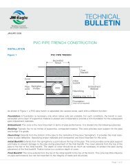
07INSTALLATIONPIPE ZONE TERMINOLOGYfigure 4PipezoneSpringlineof pipe6 in - 12 inInitialbackfillHaunchingBeddingmax. 6 inFoundation(may not be required)EmbedmentMaterialIn general, pipe laying should begin at the lowest pointand work toward manholes, service branches, or cleanouts.Pipe bells can be laid in either direction, upstreamor downstream without any significant hydraulic loss.However, common practice is to lay the bells in the directionof work progress to ease installation. Additionally, byinserting the spigot into the bell rather than pushing thebell over the spigot, the risk of soil or rubble beingscooped under the gasket is reduced. If pipe laying isinterrupted or halted, the exposed ends of the pipe lineshould be closed to prevent the entrance of trench water,mud, and foreign matter.PREPARATION OF THE TRENCH BOTTOMThe trench floor should be constructed to provide a firm,stable, and uniform support for the full length of the pipe.This can be accomplished by bringing the entire trenchfloor to a level grade and then creating bell holes at eachjoint to permit proper joint assembly, alignment, and support.Portions of the trench that are excavated below gradeshould be returned to grade and compacted as required toprovide proper support. If the native trench soil is not suitablefor the pipe bedding, the trench should be over excavatedand refilled with suitable foundation material asspecified by the engineer. A cushion of acceptable beddingmaterial should always be provided between any hardfoundation and the pipe. Large rocks, boulders, andstones should be removed to allow a minimum of 4 inchesof soil cushion on all sides of the pipe and accessories.PIPE LAYINGProper implements, tools, and equipment should be usedfor placement of the pipe in the trench to prevent damage.Avoid dropping pipe and accessories into the trench, asthis may cause damage that is not easily detected.Additional handling instructions may be sought from ourproduct installation guides or by contacting <strong>JM</strong> <strong>Eagle</strong> .BEDDINGBedding is required primarily to bring the trench bottomup to grade. Bedding materials should be placed to provideuniform longitudinal support under the pipe to preventlow spots. Blocking should not be used to bring thepipe to grade. Bell holes at every joint will allow for thejoint to be assembled properly and maintain adequatesupport. Under normal circumstances a bedding of 4 to 6inches is sufficient.HAUNCHINGThe most important factor in assuring proper pipe-soil interactionis the haunching material and its density. This materialprovides the majority of the support that the piperequires to function properly in regards to performance anddeflection. This material should be placed and consolidatedunder the pipe haunches, the area of the pipe between thespringline and the bottom of the pipe, to provide adequateside support to the pipe. In doing so, proper control shouldbe exercised to avoid vertical and horizontal displacementof the pipe from proper alignment. If the bedding material iscourse and contains voids, the same course materialshould also be used for the haunching. In order for thehaunching to provide adequate support, it must be consolidatedat regular intervals to the springline of the pipe.GRAVITY SEWER17
INSTALLATION(CONTINUED)INITIAL BACKFILLThis portion of the pipe embedment begins at the springlineof the pipe and extends to some predetermined distanceabove the top of the pipe. Since little to no sidesupport is derived from the soils placed in this area, nativesoils may be used without any special compaction efforts.However, if other structures are present such as, roadwaysor buildings, their foundation requirements mayrequire that this soil be consolidated. The main purpose ofthe placement of this native material is to protect the pipefrom contact with falling rocks or other impact loads thatmay occur when the final backfill is applied.At shallow depths of cover (less than three feet), flexible conduitsmay deflect and rebound under dynamic loading conditionsif the trench width is not highly compacted. If this highdegree of compaction is not met, road surfaces may bedamaged. For pipe buried under flexible road surfaces atdepths less than three feet, it is recommended that a minimumof 95% Proctor density be achieved from the bottom ofthe trench up to the road surface using Class I or Class IImaterials as described in the following tables. Minimumcover is recommended to be one foot from the top of rigidroad surfaces or the bottom of flexible road surfaces.FINAL BACKFILLThe material used in the final backfilling of the trench neednot be as carefully selected as the bedding, haunching,and initial backfill, with the exception of where this materialis going to be in the zone of influence of the foundationfor some present or future structure. In the final backfillmaterial the following items should be avoided: boulders,frozen clumps of dirt, and rubble that could cause damageto the pipe. Unless otherwise specified, the finalbackfill material should be placed using special compactionunder improved surfaces and shoulders of streets,roads, aprons, curbs, and walks. Under open fields,lawns, and wide shoulders, unimproved right-of-way, orneutral grounds free of traffic, final backfill should beplaced using natural compaction. Special compactionrequirements should be defined by the design engineer.Natural compaction is attained by the loose placing ofmaterial into the trench, rolling the surface layer with theplacement equipment, molding the surface, and filling andmaintaining all sunken trenches until final acceptance ofthe work. In natural compaction, the main consolidationresults from rainfall and groundwater fluctuations.EMBEDMENT MATERIALSMaterials suitable for foundation and embedment are classifiedin the following Table 1.1. They include a number ofprocessed materials plus soil types defined according to theUnified Soil Classification System (USCS) in ASTM D2487,“Standard Method for Classification of Soils for EngineeringPurposes.” Table 1.2 provides recommendations on theinstallation and use based on class of soil or aggregates andlocation within the trench. It is important to engineer all materialsused in the pipe trench to work together and with thenative material surrounding the trench.CLASS IA MATERIALSClass IA materials provide the maximum stability and pipesupport for a given density because of the angular interlockingof the material particles. With minimum efforts,these materials can be installed at relatively high densitiesover a wide range of moisture contents. These materialsalso have excellent drainage characteristics that may aidin the control of water. These soils are often desirable asembedment in rock cuts where water is frequently encountered.On the other hand, when ground water flow isanticipated, consideration should be given to potentialmigration of fines from adjacent materials into the opengraded Class IA materials.CLASS IB MATERIALSThese materials are produced by mixing Class IA andnatural or processed sands to produce a particle-sizedistribution that minimizes migration from surroundingsoils that may contain fines. They are more widely gradedthan Class IA and thus require more compaction effort toachieve the minimum density specified. When thesematerials are properly compacted, these soils exhibithigh stiffness and strength, and depending on the amountof fines, may be relatively free draining.18 GRAVITY SEWER
CLASS II MATERIALSWhen Class II materials are compacted they provide arelatively high level of pipe support. In most respects, theyall have the desirable characteristics of Class IB materialswhen widely graded. However, open-graded groups mayallow for migration and the sizes should be checked forcompatibility with the native trench materials. Typically,Class II materials consist of rounded particles and are lessstable than the angular materials of Class IA and IB, unlessthey are confined and compacted.CLASS III MATERIALSThese materials provide less support for a given densitythan Class I or Class II materials. High levels of compactiveeffort are required if moisture content is not controlled.These materials will provide reasonable support once propercompaction is achieved.CLASS IV-A MATERIALSClass IV-A materials must be carefully evaluated beforeuse. The moisture content of the materials must be nearoptimum to minimize compactive effort and achieve therequired density. Properly placed and compacted, thesesoils can provide reasonable levels of pipe support.However, these materials may not be suitable under highfills, surface applied dynamic loads, or under heavy vibratorycompactors and tampers. These materials should beavoided if water conditions in the trench may cause instabilityand result in uncontrolled water content.MIGRATIONIn soils where ground water fluctuations occur, coarse oropen-graded material placed adjacent to a finer materialmay be infiltrated by those fines. Such hydraulic gradientsmay arise during trench construction when water levelsare being controlled by various pumping or well-pointingmethods, or after construction when permeable underdrain or embedment materials act as a “French” drainunder high ground water levels. Downward percolation ofsurface water may carry fine materials down into morecoarse, open-graded bedding materials if the trench is notproperly designed and constructed. The gradation andrelative particle size of the embedment and adjacentmaterials must be compatible in order to minimize migration.As a general precaution, it is recommended that ifsignificant groundwater flow is anticipated, avoid placingcoarse, open-graded materials adjacent to finer materials,unless methods are employed to impede migration, suchas the use of an appropriate stone filter or fabric along theboundary of incompatible materials.EMBEDMENT COMPACTIONThe moisture content of embedment materials must bemaintained within suitable limits to permit placement andcompaction to required levels without exhaustive efforts.For non-free draining soils, such as Class III and IV-A,moisture content should be held close to optimum. Ifwater exists in the trench, free-draining embedment materialsare generally more suitable because they are morereadily densified when saturated. Maximum particle sizefor embedment material is limited to only those materialspassing a 1.5 inch (38 mm) sieve.When using mechanical compactors, avoid contact withthe pipe. When compacting over the pipe crown, a minimumof 6 inches of cover should be maintained whenusing small compactors. If larger compactors are used,the engineer should be consulted to specify the minimumdistance from the pipe crown. This decision will be basedon the depth of influence of the specific compactionequipment being used. For compaction with heavy wheelloading or hydro hammer methods, a minimum of 30inches over the pipe crown is required. Heavy wheel loadingor hydro hammer methods should not be used in shallowapplications where total cover is less than the influencezone of the compaction device. In shallow coverapplications, materials requiring little or no mechanicalcompaction should be used for embedment of the pipe.GRAVITY SEWER19
INSTALLATION(CONTINUED)The effectiveness of the compaction equipment necessaryto achieve desired densities for specific types ofmaterials depends on the chosen methods ability todeliver compactive energy. Coarse-grained, clean materialsare free flowing and may not require mechanical compactionin some installations. These materials are morereadily compacted using vibratory equipment. Fine materialswith high plasticity may require kneading and impactforce along with controlled water content to reach acceptabledensities. In pipe trenches, small hand-held, or walkbehind compactors, work well, not only to prevent pipedamage, but to insure thorough compaction in the confinedspaces around the pipe and along the trench wall.SHEETINGIf soil conditions or regulations require the use of sheetingor boxes, they should be used in a manner so as not todisturb the haunching material within one pipe diameter oneach side of pipe.PERMISSABLE HORIZONTAL CURVATURECurved sewers, 4" through 12" in diameter, should beaccomplished by bending the pipe rather than deflectingthe joint, per Table 2. Curves for pipe 15" and largershould be made by an allowable 1.5 degrees deflection atthe joint.20 GRAVITY SEWER
table 1.1Description of Material Classification as Defined in ASTM D2321ClassIAIBIIIIIIVAIVBtypeManufacturedAggregates:open gradedcleanManufactured,ProcessedAggregates:dense graded,cleanCoarse-Grained Soils,cleanCoarse-Grained Soils:borderlineclean to withfinesCoarse-Grained Soilswith finesFine-GrainedSoils:InorganicFine-GrainedSoils:InorganicsoilsymbolgroupnonenoneGWGPSWSPGMGCdescriptionastm d2487Angular, crushed stone or rock,crushed slag, cinders or shelllarge void content, contain littleor no finesAngular, crushed stone (or otherClass IA materials) and stone/sand mixtures with gradationsselected to minimize migration ofadjacent soils; contain littleto no finesWell-graded gravels and gravelsandmixtures; little to no finesPoorly-graded gravels and gravelsandmixtures; little to no finesWell-graded sands and gravellysands; little to no finesPoorly-graded sands and gravellysands; little to no finesSands and gravels which areborderline between clean andwith finesSilty gravels, gravel-sand-siltmixturesClayey gravels, gravel-sand-claymixtures1.5 in(40 mm)Percentage passingsieve sizes .075mmNo. 4(4.75 mm)No. 200(0.75 mm)100% < or = 10% < 5%100% < or = 50% < 5%100%< 50% ofcoarsefraction< 5%atterberglimitsLLNonPlasticNonPlasticNonPlasticPLcoeffientsUniformityCuCurvatureCc— — —— — —— > 4 1 to 3— — — — — < 4 < 1 or > 3—> 50% ofcoarsefraction— — — > 6 1 or 3— — — — — < 6 < 1 or > 3100% varies100%SM Silty sands, sand-silt mixtures —> 50% ofcoarsefraction5% to12%> 12% to< 50%NonPlastic—— — — —> 50% ofcoarsefraction— —SC Clayey sands, sand-silt mixtures — — — —MLCLMHCHInorganic silts and very finesands, rock flour, silty orclayey fine sands, silts with slightplasticityInorganic clays of low tomedium plasticity, gravelyclays, sandy clays, siltyclays, lean claysInorganic silts, micaceous ordiatomaceous fine sandy orsilty soils, elastic siltsInorganic clays of highplasticity, fat clays100% 100% > 50% < 50— — — —— —< 4 or”A” Line> 4 or 7 and>”A” Line< 4 or 7 and>”A” LineSame asfor GW,GP, SW,and SP— —— —— —— —— —— —100% 100% > 50% > 50 < ”A” Line — —— — — —> “A”LIne— —V Organic Soils OLOrganic silts and organic siltyclays of low plasticity100% 100% > 50% < 50< 4 or 50
INSTALLATION(CONTINUED)table 1.2Recommendations for Installation and Use of Soils and Aggregates for Foundation, Embedment and Backfill.Soil class as defined in table 1.1Class IA Class IB class II class III Class iv-aGeneralRecommendationsand RestrictionsDo not use whereconditions may causemigration of fines fromadjacent soil and loss ofpipe support. Suitablefor use as a drainageblanket and underdrainin rock cuts where adjacentmaterial is suitablygraded.Process materials asrequired to obtaingradation which willminimize migrationof adjacent materials.Suitable for use asdrainage blanketand underdrain.Where hydraulicgradient exist checkgradation to minimizemigration. “Clean”groups suitable for useas drainage blanket andunderdrain.Do not use wherewater conditionsin trench maycause instability.Obtain geotechnicalevaluation of processedmaterial. May not be suitableunder high earth fills, surfaceapplied loads and underheavy vibratory compactorsand tampers. Do not usewhere water conditions intrench may cause instability.FoundationSuitable as foundationand for replacing overexcavatedand unstabletrench bottom as restrictedabove. Install andcompact in 6 inchmaximum layers.Suitable as foundationand for replacingover-excavated andunstable trenchbottom. Install andcompact in 6 inchmaximum layers.Suitable as foundationand for replacingover-excavated andunstable trench bottomas restricted above.Install and compact in 6inch maximum layers.—Suitable only in undisturbedconditions and where trenchis dry. Remove all loosematerial and provide firm, uniformtrench bottom beforebedding is placed.BeddingSuitable as restrictedabove. Install in 6 inchmaximum layers. Levelfinal grade by hand.Minimum depth 4 inches(6 inches in rock cuts).Install and compact in6 inch maximum layers.Level final gradeby hand. Minimumdepth4 inches (6 inchesin rock cuts).Suitable as restrictedabove. Install and compactin 6 inchmaximum layers.Level final grade byhand. Minimum depth4 inches (6 inches inrock cuts).Suitable only in drytrench conditions.Install and compactin 6 inch maximumlayers. Level finalgrade by hand.Minimum depth 4inches(6 inches ofrock cuts).Suitable only in dry trenchconditions and whenoptimum placement andcompaction control is maintained.Install and compact in6 inch maximum layers.Level final grade by hand.Minimum depth 4 inches(6 inches in rock cuts).HaunchingSuitable as restrictedabove. Install in 6 inchmaximum layers. Work inaround pipe by hand toprovide uniform support.Install and compact in6 inch maximum layers.Work in aroundpipe byhand to provideuniform support.Suitable as restrictedabove. Install andcompact in 6 inchmaximum layers.Work in around pipeby hand to provideuniform support.Suitable as restrictedabove. Installandcompact in 6 inchmaximum layers.Work in aroundpipe by handto provideuniform support.Suitable only in dry trenchconditions and whenoptimum placement andcompaction control ismaintained. Install andcompact in 6 inch maximumlayers. Work in aroundpipe by hand to provideuniform support.Initial BackfillSuitable as restrictedabove. Install to aminimum of 6 inchesabove pipe crown.Install and compactto a minimum of6 inches abovepipe crown.Suitable as restrictedabove. Install andcompact to aminumum of 6 inchesabove pipe crown.Suitable as restrictedabove. Installand compact to aminumum of 6inches above pipecrown.Suitable as restricted above.Install and compact to aminumum of 6 inches abovepipe crown.Final BackfillCompact as requiredby the engineer.Compact as requiredby the engineer.Compact as requiredby the engineer.Compact asrequired bythe engineer.Suitable as restrictedabove. Compact asrequired by the engineer.22 GRAVITY SEWER
table 1.3Provides an approximate guide to obtainable densities of various soils by several compaction methods. Minimum densitiesrequired will depend on the depth of cover, pipe stiffness, and type of soil used. In most situations, the project engineer willdetermine the appropriate values during the design.Estimated range of compaction by embedment class and methodClass of Embedment I II III IVMaterial DescriptionOptimum Moisture ContentRange % of dry weightSoil Consolidation MethodManufacturedGranular MaterialsSand and Gravel, clean Mixed-Grain Fine-Grain— 9 to 12 9 to 18 6 to 30% of Proctor (or Relative) Density RangePower Tamper or Rammer 95 - 100 (75 - 100) 95 - 100 (80 - 100) 95 - 100 90 - 100Portable Vibrator 80 - 95 (60 - 75) 80 - 95 (60 - 80) 80 - 95 75 - 90Consolidation by Saturation 80 - 95 (60 - 75) 80 - 95 (60 - 80) — —Hand Place 60 - 80 (40 - 60) — — —Hand Tamp — 60 - 80 (50 - 60) 60 - 80 60 - 75Dump 60 - 80 (40 - 60) 60 - 80 (50 - 60) 60 - 80 60 - 75GRAVITY SEWER23
08Short form installation guideThis information is furnished in order to provide a brief review of the installation requirements for <strong>JM</strong> <strong>Eagle</strong> Ring-Tite PVC<strong>Sewer</strong> pipe. It is not intended to serve as or replace the FULL VERSION of the complete product installation guide availableupon request.1. Check to see that the gasket is properly seated in the bell groove, and that the bell and spigot are cleanbefore assembly.2. Apply the approved lubricant supplied with the pipe to the spigot end of the pipe, paying particular attention to the bevel.The coating should be equivalent to a brush coat of enamel paint.3. Assemble the joint only to and not over the assembly mark provided on the spigot end.4. If undue resistance to insertion of the spigot is encountered, or the assembly mark does not reach the flush position,disassemble the joint and check the position of the rubber gasket, and remove any debris.PIPE SIZE (IN) RADIUS (FT)4 1006 1508 20010 25012 3005. Curvature of the pipe shall be accomplished through longitudinal bendingof the pipe barrel in accordance with the following table. Deflection of thejoint is not allowed and may cause leaks. For bending of pipe larger than12", 1.5 degrees of joint deflection is allowed. This will result in an offset of6¼" per 20' length.6. Prior to backfilling, check to see that the reference mark is flush with theend of the bell.24 GRAVITY SEWER
09WARRANTY<strong>JM</strong> EAGLE PRODUCTS LIMITED WARRANTYJ-M Manufacturing Co., Inc. (<strong>JM</strong> <strong>Eagle</strong> ) warrants that its standard polyvinyl chloride (PVC), polyethylene (PE), conduit/plumbing/solvent weld and Acrylonitrile-Butadiene-Styrene (ABS) pipe <strong>Product</strong>s (“<strong>Product</strong>s”) are manufactured inaccordance with applicable industry specifications referenced on the <strong>Product</strong> and are free from defects in workmanshipand materials. Every claim under this warranty shall be void unless in writing and received by <strong>JM</strong> <strong>Eagle</strong> within thirty (30)days of the date the defect was discovered, and within one (1) year of the date of shipment from the <strong>JM</strong> <strong>Eagle</strong> plant.Claims for <strong>Product</strong> appearance defects, such as sun-bleached pipe etc., however, must be made within thirty (30) days ofthe date of the shipment from the <strong>JM</strong> <strong>Eagle</strong> plant. This warranty specifically excludes any <strong>Product</strong>s allowed to becomesun-bleached after shipment from the <strong>JM</strong> <strong>Eagle</strong> plant. Proof of purchase with the date thereof must be presented to thesatisfaction of <strong>JM</strong> <strong>Eagle</strong> , with any claim made pursuant to this warranty. <strong>JM</strong> <strong>Eagle</strong> must first be given an opportunity toinspect the alleged defective <strong>Product</strong>s in order to determine if it meets applicable industry standards, if the handling andinstallation have been satisfactorily performed in accordance with <strong>JM</strong> <strong>Eagle</strong> recommended practices and if operatingconditions are within standards. Written permission and/or a Return Goods Authorization (RGA) must be obtained alongwith instructions for return shipment to <strong>JM</strong> <strong>Eagle</strong> of any <strong>Product</strong>s claimed to be defective.The limited and exclusive remedy for breach of this Limited Warranty shall be, at <strong>JM</strong> <strong>Eagle</strong>’s sole discretion, thereplacement of the same type, size and like quantity of non-defective <strong>Product</strong>, or credits, offsets, or combination of thereof,for the wholesale purchase price of the defective unit.This Limited Warranty does not apply for any <strong>Product</strong> failures caused by user’s flawed designs or specifications,unsatisfactory applications, improper installations, use in conjunction with incompatible materials, contact with aggressivechemical agents, freezing or overheating of liquids in the product and any other misuse causes not listed here. This LimitedWarranty also excludes failure or damage caused by fire stopping materials, thread sealants, plasticized vinyl <strong>Product</strong>s ordamage caused by the fault or negligence of anyone other than <strong>JM</strong> <strong>Eagle</strong> , or any other act or event beyond the controlof <strong>JM</strong> <strong>Eagle</strong> .<strong>JM</strong> <strong>Eagle</strong>’s liability shall not, at any time, exceed the actual wholesale purchase price of the <strong>Product</strong>. The warrantiesin this document are the only warranties applicable to the <strong>Product</strong> and there are no other warranties, expressed orimplied. This Limited Warranty specifically excludes any liability for general damages, consequential or incidental damages,including without limitation, costs incurred from removal, reinstallation, or other expenses resulting from any defect. IMPLIEDWARRANTIES OF MERCHANTABILITY OR FITNESS FOR A PARTICULAR PURPOSE ARE SPECIFICALLY DISCLAIMEDAND <strong>JM</strong> EAGLE SHALL NOT BE LIABLE IN THIS RESPECT NOTWITHSTANDING <strong>JM</strong> EAGLE’S ACTUAL KNOWLEDGETHE PRODUCT’S INTENDED USE.<strong>JM</strong> <strong>Eagle</strong>’s <strong>Product</strong>s should be used in accordance with standards set forth by local plumbing and building laws,codes, or regulations and the applicable standards. Failure to adhere to these standards shall void this Limited Warranty.<strong>Product</strong>s sold by <strong>JM</strong> <strong>Eagle</strong> that are manufactured by others are warranted only to the extent and limits of the warranty ofthe manufacturer. No statement, conduct or description by <strong>JM</strong> <strong>Eagle</strong> or its representative, in addition to or beyond thisLimited Warranty, shall constitute a warranty. This Limited Warranty may only be modified in writing signed by an officerof <strong>JM</strong> <strong>Eagle</strong> .GRAVITY SEWER25
Notes:
plant LocationsADEL2101 J-M DriveAdel, Georgia 31620MAGNOLIA2220 Duracrete DriveMagnolia, Arkansas 71753VISALIA8875 Avenue 304Visalia, California 93291BATCHELOR2894 Marion Monk RoadBatchelor, Louisiana 70715MCNARY31240 Roxbury RoadUmatilla, Oregon 97882WHARTON10807 US 59 RDWharton, Texas 77488BUTNER2602 West Lyon Station RoadCreedmoor, North Carolina 27522MEADVILLE15661 Delano RoadCochranton, Pennsylvania 16314WILTON1314 W. Third StreetWilton, Iowa 52778CAMERON PARK3500 Robin LaneCameron Park, California 95682COLUMBIA6500 North Brown Station RoadColumbia, Missouri 65202CONROE101 East Avenue MConroe, Texas 77301PERRIS23711 Rider StreetPerris, California 92570PUEBLO1742 E. Platteville BoulevardPueblo West, Colorado 81007STOCKTON1051 Sperry RoadStockton, California 95206MEXICOPLASTICS TECHNOLOGYDE MÉXICO S DE R.L. DE S.A.Av. Montes Urales No. 8 y 10Parque Industrial Opción, Carretera57 Qro. -S.L.P. Km. 57.8C.P. 37980 San José Iturbide,Guanajuato México* Our Mexico location is a jointventure between <strong>JM</strong> <strong>Eagle</strong> andPlastics TechnologyFONTANA10990 Hemlock AvenueFontana, California 92337SUNNYSIDE1820 South First StreetSunnyside, Washington 98944GLOBAL HEADQUARTERS5200 West Century BoulevardLos Angeles, California 90045HASTINGS146 North Maple AvenueHastings, Nebraska 68901TACOMA2330 Port of Tacoma RoadTacoma, Washington 98421REGIONAL OFFICENine Peach Tree Hill RoadLivingston, New Jersey 07039KINGMAN4620 Olympic WayKingman, Arizona 86401TULSA4501 West 49th StreetTulsa, Oklahoma 74107J-M Manufacturing Co., Inc. and PW <strong>Eagle</strong>, Inc. are doing business as <strong>JM</strong> <strong>Eagle</strong> .
<strong>JM</strong> <strong>Eagle</strong>• The leader in pipe innovation• The highest level of quality• The largest breadth of product• The widest capacity• Express deliveryTacomaSunnysideMcNaryCameron ParkStocktonVisaliaKingmanFontanaPerrisPuebloWiltonHastingsColumbiaTulsaMagnoliaMeadvilleButnerConroeWhartonBatchelorAdelMexicoPlant LocationsRevised March 2011<strong>JM</strong>E-05A© J-M Manufacturing Co., Inc.Building essentialsfor a better tomorrowGLOBAL HEADQUARTERS:5200 West Century BlvdLos Angeles, CA 90045T: 800.621.4404F: 800.451.4170www.<strong>JM</strong><strong>Eagle</strong>.comREGIONAL OFFICE:Nine Peach Tree Hill RoadLivingston, NJ 07039T: 973.535.1633F: 973.533.4185