BLUE BRUTEâ¢/ BIG BLUEâ¢/ ULTRA BLUE⢠- JM Eagle
BLUE BRUTEâ¢/ BIG BLUEâ¢/ ULTRA BLUE⢠- JM Eagle
BLUE BRUTEâ¢/ BIG BLUEâ¢/ ULTRA BLUE⢠- JM Eagle

Create successful ePaper yourself
Turn your PDF publications into a flip-book with our unique Google optimized e-Paper software.
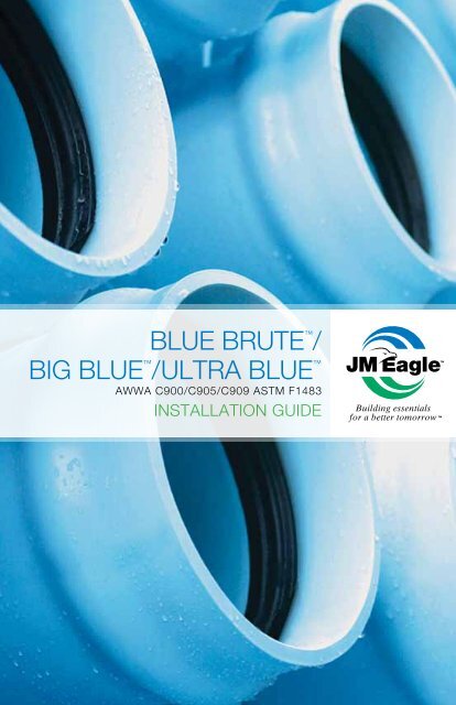
<strong>BLUE</strong> BRUTE /big blue / <strong>ULTRA</strong> <strong>BLUE</strong> AWWA C900/C905/C909 ASTM F1483INSTALLATION GUIDEBuilding essentialsfor a better tomorrow
WARNINGRUPTURE HAZARDImproper installation or misuse of tapping tools may causepipes under high pressure to rupture and result in highvelocity airborne fragmentation leading to serious injuriesand/or death.• Before and during installation, always:• Consult and follow the FULL VERSION of the productinstallation guide• Closely follow job specifications• Use protective gear and equipment• Before and during tapping, always:• Consult and follow Uni-Bell ® Publication Uni-PUB-08-07,“Tapping Guide for PVC Pressure Pipe.”• Use the correct tapping tools• Bleed air from pipes at high spot before tapping• Use protective gear and equipmentPlease contact <strong>JM</strong> <strong>Eagle</strong> Product Assurance at (800) 621-4404to obtain full version of the appropriate installation guideor for further assistance.
lue brute /big blue / <strong>ULTRA</strong> <strong>BLUE</strong> Contents1.02.0Receiving and Handling Pipe Shipments . . . . . . . . . . . . . . . . . . . . 81.11.21.31.41.51.61.72.12.22.32.42.52.62.7Inspection . . . . . . . . . . . . . . . . . . . . . . . . . . . . . . . . . . . . . . . . . . . . . 8Unloading . . . . . . . . . . . . . . . . . . . . . . . . . . . . . . . . . . . . . . . . . . . . . 9Cold Weather Handling . . . . . . . . . . . . . . . . . . . . . . . . . . . . . . . 11Stockpiles . . . . . . . . . . . . . . . . . . . . . . . . . . . . . . . . . . . . . . . . . . . . 11Gasket Care . . . . . . . . . . . . . . . . . . . . . . . . . . . . . . . . . . . . . . . . . 12Loading Transfer Trucks . . . . . . . . . . . . . . . . . . . . . . . . . . . . . 12Distributing Along the Trench . . . . . . . . . . . . . . . . . . . . . . . . 13Trench Construction . . . . . . . . . . . . . . . . . . . . . . . . . . . . . . . . . . . 13Working Ahead of the Pipe Laying Crew . . . . . . . . . . . . . . . . 13Curves in the Trench . . . . . . . . . . . . . . . . . . . . . . . . . . . . . . . . . .142.2.12.2.2Blue Brute AWWA C900 andUltra Blue AWWA C909 (4"-16") . . . . . . . . . . . . . . . . . . . . 14Big Blue AWWA C905 (14"- 48") . . . . . . . . . . . . . . . . . . . . . .15Trench Widths . . . . . . . . . . . . . . . . . . . . . . . . . . . . . . . . . . . . . . . . 16Trench Depths . . . . . . . . . . . . . . . . . . . . . . . . . . . . . . . . . . . . . . . . 17Planning for Thrusting . . . . . . . . . . . . . . . . . . . . . . . . . . . . . . . 17Preparation of Trench Bottom . . . . . . . . . . . . . . . . . . . . . . . . 18Casings . . . . . . . . . . . . . . . . . . . . . . . . . . . . . . . . . . . . . . . . . . . . . . . 182.7.12.7.2Placement of Casings . . . . . . . . . . . . . . . . . . . . . . . . . . . 18Pulling the Pipe . . . . . . . . . . . . . . . . . . . . . . . . . . . . . . . . . .19
3.04.03.13.23.33.43.53.63.73.83.92.7.3Closure of Casing After Pipe Installation . . . . . . . 21Pipeline Construction . . . . . . . . . . . . . . . . . . . . . . . . . . . . . . . . . . 233.103.113.12Inspection . . . . . . . . . . . . . . . . . . . . . . . . . . . . . . . . . . . . . . . . . . . 23Lowering Pipe and Accessories into Trench . . . . . . . . . . 23Assembly of <strong>JM</strong> EAGLE PVC Pipe . . . . . . . . . . . . . . . . . . . . . . . 24Assembly Instructions . . . . . . . . . . . . . . . . . . . . . . . . . . . . . . . 24Cutting . . . . . . . . . . . . . . . . . . . . . . . . . . . . . . . . . . . . . . . . . . . . . . 27Beveling . . . . . . . . . . . . . . . . . . . . . . . . . . . . . . . . . . . . . . . . . . . . . 28Locating Reference Mark . . . . . . . . . . . . . . . . . . . . . . . . . . . . 28Assembly at Fittings and Adaptors . . . . . . . . . . . . . . . . . . . 28Thrust Blocking and Anchorage at Fittings . . . . . . . . . . 293.9.13.9.23.9.33.9.43.9.5Determining Size and Type of Thrust Blocking . . . 29Upward Thrusts at Fittings . . . . . . . . . . . . . . . . . . . . . 32Anchorage of Pipe on Slopes . . . . . . . . . . . . . . . . . . . 32Anchorage of Valves in the Line . . . . . . . . . . . . . . . . . 33Construction of Thrust Backing . . . . . . . . . . . . . . . 33Installation at Hydrants . . . . . . . . . . . . . . . . . . . . . . . . . . . . 33Thrust-Restraint Joints . . . . . . . . . . . . . . . . . . . . . . . . . . . . . 34Service Connections . . . . . . . . . . . . . . . . . . . . . . . . . . . . . . . . 353.12.1Direct Taps, Saddles, and Valves . . . . . . . . . . . . . . . 35Pipe Embedment . . . . . . . . . . . . . . . . . . . . . . . . . . . . . . . . . . . . . . . . . 354.14.24.2.14.34.4Bedding . . . . . . . . . . . . . . . . . . . . . . . . . . . . . . . . . . . . . . . . . . . . . . 36Backfilling and Tamping . . . . . . . . . . . . . . . . . . . . . . . . . . . . . . 36Haunching and Initial Backfill . . . . . . . . . . . . . . . . . . 36Completing the Backfill . . . . . . . . . . . . . . . . . . . . . . . . . . . . . . 384.3.1Final Backfill . . . . . . . . . . . . . . . . . . . . . . . . . . . . . . . . . . 38Compaction Methods . . . . . . . . . . . . . . . . . . . . . . . . . . . . . . . . . 39
5.04.4.14.4.24.4.34.4.44.4.5Tamping Bars . . . . . . . . . . . . . . . . . . . . . . . . . . . . . . . . . . 39Mechanical Tampers . . . . . . . . . . . . . . . . . . . . . . . . . . . 40Flood or Water Tamping . . . . . . . . . . . . . . . . . . . . . . . . 40Water-Jetting . . . . . . . . . . . . . . . . . . . . . . . . . . . . . . . . . . 41Sheeting and Trench Boxes . . . . . . . . . . . . . . . . . . . . . 41Pipe Testing and Repair . . . . . . . . . . . . . . . . . . . . . . . . . . . . . . . . . . 415.15.1.15.25.35.45.5Pipe Deflection . . . . . . . . . . . . . . . . . . . . . . . . . . . . . . . . . . . . . . . 41Deflection Testing . . . . . . . . . . . . . . . . . . . . . . . . . . . . . 42Testing Water Pipe . . . . . . . . . . . . . . . . . . . . . . . . . . . . . . . . . . . . 425.2.15.2.2Filling the Line . . . . . . . . . . . . . . . . . . . . . . . . . . . . . . . . . 43Relieving Air from the Line . . . . . . . . . . . . . . . . . . . . . 45Pressure-Strength Tests . . . . . . . . . . . . . . . . . . . . . . . . . . . . . 45Making Leakage Tests . . . . . . . . . . . . . . . . . . . . . . . . . . . . . . . . . 46Making Repairs to Damaged Pipelines . . . . . . . . . . . . . . . . . . 48Appendix 1 . . . . . . . . . . . . . . . . . . . . . . . . . . . . . . . . . . . . . . . . . 49
The physical (or chemical) properties of <strong>JM</strong> <strong>Eagle</strong> Blue Brute PVC C.I.O.D.Distribution Pipe (AWWA C900) ,Big Blue PVC C.I.O.D. Transmission Pipe (AWWAC905), Ultra Blue PVCO C.I.O.D. Distribution Pipe (AWWA C909), and UltraBlue PVCO I.P.S. Distribution Pipe (ASTM F1483) presented in this booklet,represent typical average values obtained in accordance with acceptedtest methods and are subject to normal manufacturing variations. Theyare supplied as a technical service and are subject to change withoutnotice. Check with <strong>JM</strong> <strong>Eagle</strong> Product Assurance to ensure currentinformation.How This Guide Can Help YouThis booklet was written especially for the installer and those who directactual handling and installation of <strong>JM</strong> <strong>Eagle</strong> PVC Blue Brute , Big Blue , andUltra Blue pipe. This guide should be used in conjunction with the followingindustry accepted installation and testing practices which are applicable.This document should not be considered a full guide or manual in lieu of:1. ASTM D2774-04 (or later) “Underground Installation of ThermoplasticPressure Piping.”2. ASTM F690-86 (2003) (or later) “Underground Installation ofThermoplastic Pressure Piping Irrigation Systems.”3. ASTM F1668-96 (2002) (or later) “Construction of Procedures forBuried Plastic Pipe.”4. ASTM F645-04 (or later) “Selection, Design, and Installation ofThermoplastic Water-Pressure Piping Systems.”5. ASTM D2321-05 (or later) Underground Installation of ThermoplasticPipe for Sewers and Other Gravity-Flow Applications.”6. ASTM F1417-92 (2005) (or later) “Installation Acceptance of PlasticGravity Sewer Lines Using Low-Pressure Air.”7. AWWA C605 “Underground Installation of Polyvinyl Chloride (PVC)Pressure Pipe and Fittings for Water.”4 <strong>BLUE</strong> BRUTE /<strong>BIG</strong> <strong>BLUE</strong> /<strong>ULTRA</strong> <strong>BLUE</strong> INSTALLATION GUIDE
8. AWWA C651 “Disinfecting Water Mains.”9. AWWA M23 “PVC Pipe – Design and Installation.”10. Uni-Bell ® UNI-PUB-09 “Installation Guide for PVC Pressure Pipe.”11. Uni-Bell ® UNI-B-6 “Recommended Practice for Low-Pressure AirTesting of Installed Sewer Pipe.”12. Uni-Bell ® UNI-PUB-06 “Installation Guide for PVC Solid-Wall SewerPipe (4-15 Inch).”13. Uni-Bell ® UNI-TR-1 “Deflection: The Pipe/Soil Mechanism.”14. Uni-Bell ® UNI-TR-6 “PVC Force Main Design.”15. Uni-Bell ® UNI-TR-7 “Thermoplastic Pressure Pipe Design and Selection.”This guide is meant as an explanatory supplement to the materials aboveon how to install <strong>JM</strong> <strong>Eagle</strong> PVC Blue Brute , Big Blue , and Ultra Blue pipe under normal conditions so as to comply with Standard <strong>JM</strong> <strong>Eagle</strong> Laying Specifications. Any discrepancies between the above standards andthe written information contained herein, should be brought to the attentionof <strong>JM</strong> <strong>Eagle</strong> Product Assurance immediately for resolution by <strong>JM</strong> <strong>Eagle</strong> ,prior to any actions by either contractor, engineer, or municipality.This guide is not intended to supply design information nor to assume theresponsibility of the engineer (or other customer representative) inestablishing procedures best suited to individual job conditions so as to attainsatisfactory performance.Engineers, superintendents, contractors, foremen, and laying crews will findmuch to guide them in the following specifications. This booklet will also beof help in determining pipe needs when ordering.<strong>BLUE</strong> BRUTE /<strong>BIG</strong> <strong>BLUE</strong> /<strong>ULTRA</strong> <strong>BLUE</strong> INSTALLATION GUIDE5
WarrantyJ-M Manufacturing Company Inc. (<strong>JM</strong> <strong>Eagle</strong> ) warrants that its standardpolyvinyl chloride (PVC), polyethylene (PE), conduit/plumbing/solvent weldand Acrylonitrile-Butadiene-Styrene (ABS) pipe products (“Products”)are manufactured in accordance with applicable industry specificationsreferenced on the Product and are free from defects in workmanshipand materials. Every claim under this warranty shall be void unless inwriting and received by <strong>JM</strong> <strong>Eagle</strong> within 30 days of the date the defectwas discovered, and within one year of the date of shipment from the<strong>JM</strong> <strong>Eagle</strong> plant. Claims for Product appearance defects, such as sunbleachedpipe etc., however, must be made within 30 days of the date ofthe shipment from the <strong>JM</strong> <strong>Eagle</strong> plant. This warranty specifically excludesany Products allowed to become sun-bleached after shipment from the<strong>JM</strong> <strong>Eagle</strong> plant. Proof of purchase with the date thereof must be presented tothe satisfaction of <strong>JM</strong> <strong>Eagle</strong> , with any claim made pursuant to this warranty.<strong>JM</strong> <strong>Eagle</strong> must first be given an opportunity to inspect the alleged defectiveProducts in order to determine if it meets applicable industry standards, if thehandling and installation have been satisfactorily performed in accordancewith <strong>JM</strong> <strong>Eagle</strong> recommended practices and if operating conditions arewithin standards. Written permission and/or a Return Goods Authorization(RGA) must be obtained along with instructions for return shipment to <strong>JM</strong><strong>Eagle</strong> of any Products claimed to be defective.The limited and exclusive remedy for breach of this Limited Warranty shallbe, at <strong>JM</strong> <strong>Eagle</strong>’s sole discretion, the replacement of the same type, sizeand like quantity of non-defective Product, or credits, offsets or combinationof thereof, for the wholesale purchase price of the defective unit.This Limited Warranty does not apply for any Product failures causedby user’s flawed designs or specifications, unsatisfactory applications,improper installations, use in conjunction with incompatible materials,contact with aggressive chemical agents, freezing or overheating of liquidsin the Product, and any other misuse causes not listed here. This LimitedWarranty also excludes failure or damage caused by fire stopping materials,tread sealants, plasticized vinyl products or damage caused by the fault ornegligence of anyone other than <strong>JM</strong> <strong>Eagle</strong> , or any other act or event beyondthe control of <strong>JM</strong> <strong>Eagle</strong> .6 <strong>BLUE</strong> BRUTE /<strong>BIG</strong> <strong>BLUE</strong> /<strong>ULTRA</strong> <strong>BLUE</strong> INSTALLATION GUIDE
<strong>JM</strong> <strong>Eagle</strong>’s liability shall not, at any time, exceed the actual wholesalepurchase price of the Product. The warranties in this document are theonly warranties applicable to the Product and there are no other warranties,expressed or implied. This Limited Warranty specifically excludes anyliability for general damages, consequential or incidental damages,including without limitation, costs incurred from removal, reinstallation,or other expenses resulting from any defect. IMPLIED WARRANTIES OFMERCHANTABILITY OR FITNESS FOR A PARTICULAR PURPOSE ARESPECIFICALLY DISCLAIMED AND <strong>JM</strong> <strong>Eagle</strong> SHALL NOT BE LIABLE INTHIS RESPECT NOTWITHSTANDING <strong>JM</strong> <strong>Eagle</strong>’s ACTUAL KNOWLEDGETHE PRODUCT’S INTENDED USE.<strong>JM</strong> <strong>Eagle</strong>’s Products should be used in accordance with standards setforth by local plumbing and building laws, codes or regulations and theapplicable standards. Failure to adhere to these standards shall void thisLimited Warranty. Products sold by <strong>JM</strong> <strong>Eagle</strong> that are manufactured byothers are warranted only to the extent and limits of the warranty of themanufacturer. No statement, conduct or description by <strong>JM</strong> <strong>Eagle</strong> or itsrepresentative, in addition to or beyond this Limited Warranty, shall constitutea warranty. This Limited Warranty may only be modified in writing signed byan officer of <strong>JM</strong> <strong>Eagle</strong> .<strong>BLUE</strong> BRUTE /<strong>BIG</strong> <strong>BLUE</strong> /<strong>ULTRA</strong> <strong>BLUE</strong> INSTALLATION GUIDE7
1.0 Receiving and Handling Pipe ShipmentsFigure 11.1 InspectionEach pipe shipment shall be inspected with care upon arrival. Each pipeshipment is carefully loaded at the factory using methods acceptable to thecarrier. The carrier is then responsible for delivering the pipe as receivedfrom <strong>JM</strong> <strong>Eagle</strong> . All shipments include an adequate amount of lubricantfor the pipe and a short form installation guide. IT IS THE RESPONSIBILTYOF THE RECEIVER TO MAKE CERTAIN THERE HAS BEEN NO LOSS ORDAMAGE (including smoke) UPON ARRIVAL.Check the materials, pipe, gaskets and fittings received against the bill oflading (tally sheet that accompanies every shipment) in accordance with thegeneral guidelines below, reporting any error or damage to the transportationcompany representative and have proper notation made on the deliveryreceipt and signed by the driver. Present the claim in accordance with thecarrier’s instructions. Do not dispose of any damaged material. The carrierwill advise you of the procedure to follow in order to procure samples andreport the incident.1. MAKE OVERALL EXAMINATION OF THE LOAD. If the load is intact,ordinary inspection while unloading should be enough to make sure thepipe has arrived in good condition.2. IF LOAD HAS SHIFTED OR SHOWS ROUGH TREATMENT, THENEACH PIECE MUST BE CAREFULLY INSPECTED FOR DAMAGE.8 <strong>BLUE</strong> BRUTE /<strong>BIG</strong> <strong>BLUE</strong> /<strong>ULTRA</strong> <strong>BLUE</strong> INSTALLATION GUIDE
A method of protecting pipe during long exposures (several months) to sunlightis to cover it with canvas or other opaque material. Clear plastic sheets are notsatisfactory. Allow for adequate air circulation between the cover and the pipe.This will prevent heat build-up and possible dimensional distortion.1.5 Gasket CareAll <strong>JM</strong> <strong>Eagle</strong> PVC pipe is manufactured with factory installed gaskets.These gaskets cannot be easily removed or replaced outside of the factory.Keep them clean, away from oil, grease, excessive heat and electric motors,which produce ozone. It is advisable to keep gaskets protected from directsunlight and temperature changes in order to avoid cracking in prolongedexposure for optimal performance. <strong>JM</strong> <strong>Eagle</strong> provides a gasket that isapproved for water service with its standard product. Special gasket typesmay be available for applications where oil resistance is required. Be surethe correct ring is ordered. See Section 3.4 for further information.1.6 Loading Transfer TrucksUse trucks with long bodies so that pipe lengths do not over hang more thantwo (2) feet. Make certain truck bed is smooth, without cross-strips, boltheads, or other protrusions that could damage the pipe.Place the first layer carefully with the bell ends overhanging. Avoid sliding thepipe and abrading it. Subsequent layers can be slid into place. All bell endsshould overhang the layer below.Short body trucks may be used if fitted with racks that properly support thepipe in the horizontal position. The rack shall support the pipe with supportsspaced every three (3) feet or less along the pipe lengths. Pad the contactareas to avoid damage to the pipe.12 <strong>BLUE</strong> BRUTE /<strong>BIG</strong> <strong>BLUE</strong> /<strong>ULTRA</strong> <strong>BLUE</strong> INSTALLATION GUIDE
1.7 Distributing Along the TrenchIn stringing out pipe, keep these points in mind:1. Line pipe as near to the trench as possible to avoid excessive handling.(Bell direction has a negligible affect on flow and hydraulic coefficients.)2. If the trench is open, it is advisable to string pipe on the side away fromexcavated earth wherever possible, so that the pipe can be movedeasily to the edge of the trench for lowering into position.3. If the trench is not yet open, find out which side the excavated earth will bethrown; then string out on the opposite side (leave room for the excavator).4. Place the pipe so as to protect it from traffic and heavy equipment.Also, safeguard it from the effect of any blasting that may be done.2.0 Trench Construction2.1 Working Ahead of the Pipe Laying CrewWhere soil and ground water conditions permit, long stretches of trench can beopened ahead of pipe laying, so as to take full advantage of the easy handlingand speed of assembly of <strong>JM</strong> <strong>Eagle</strong> PVC Blue Brute , Big Blue and UltraBlue pipe with elastomeric joints. However, for most jobs as a general rule, donot open the trench too far ahead of pipe laying. Avoiding these long stretchesof opened trench may help with the economy of the project because:1. It may reduce or even eliminate pumping or sheeting.2. It minimizes the possibility of flooding the trench.3. It reduces caving caused by ground water.4. It helps avoid frozen trench bottom and backfill.5. It reduces hazards to traffic and workmen.On most jobs it will be desirable to keep excavating, pipe laying and backfillingclose together.<strong>BLUE</strong> BRUTE /<strong>BIG</strong> <strong>BLUE</strong> /<strong>ULTRA</strong> <strong>BLUE</strong> INSTALLATION GUIDE13
2.2 Curves in the Trench2.2.1 Blue Brute AWWA C900 (4 inches to 12 inches) andUltra Blue AWWA C909 (6 inches to 16 inches)The trench may be curved to change direction or avoid obstructions withinthe limits of the curvature of the pipe as shown in Table 1:PIPE SIZE(inches)MINIMUM RADIUS(feet)OFFSET(in)4 100 24.086 150 16.028 200 12.0110 250 9.6112 300 8.00Table 1* Offset based on 20 feet length of pipe forming a true arc.The line may be assembled above ground, in a straight line, and then curvedwhen laid in the trench. All curvature results from the bending of the pipelengths. The maximum angular deflection at the joint is 1 degree. Theapproximate force per 20-foot length in pounds to accomplish these curvaturesis shown in Table 2 (based on DR):PIPE SIZE(inches)DR 25 DR 18 DR 144 16.36 21.62 26.326 47.21 60.85 74.258 102.77 135.79 165.2910 185.35 245.54 299.2712 309.09 407.09 498.65Table 214 <strong>BLUE</strong> BRUTE /<strong>BIG</strong> <strong>BLUE</strong> /<strong>ULTRA</strong> <strong>BLUE</strong> INSTALLATION GUIDE
NOTICE: Mechanical means should not be employed to accomplish theseradii. It is the intent that the workers should accomplish this manually in thetrench. ON 4-INCH TO 12-INCH, THE CURVE CAN BE ACCOMPLISHEDBY BENDING THE PIPE. TO AVOID OVER-STRESSING THE BELL ANDTO PREVENT POSSIBLE BREAKAGE AND/OR LEAKS, THE MAXIMUMANGULAR DEFLECTION IN THE JOINTS IS 1 DEGREE.To avoid deflecting the joints while achieving curvature, it is recommendedthat the joints be sufficiently braced or backfilled and compacted to keep themstationary. Abrupt changes in direction shall be accomplished with fittings.2.2.2 Big Blue AWWA C905 (14 inches to 48 inches) andultra blue AWWA C909 (16 inches)Since the moment of inertia of Big Blue Pressure Pipe is high, attemptingto curve the pipe is extremely difficult. <strong>JM</strong> <strong>Eagle</strong>’s recommendation for14-inchthrough 48-inch-diameter Big Blue and 16-inch Ultra Blue isthat the angular deflection at the joint is a maximum of 1.5 degrees.This will produce an offset in a 20-foot section of approximately 6.25inches. Joint deflection is achieved after the joint is assembled in straightalignment and to the reference mark. The bell should be braced in orderto allow the free end to move laterally under steady pressure usinga pry bar or other suitable means. Care should be taken not to exceedthe maximum deflection allowed or damage the pipe with the machineryused. The line may be assembled above ground, in a straight line then offsetwhen laid in the trench, if necessary. Abrupt changes in direction shall beaccomplished with fittings.NOTICE: AVOID OVER-STRESSING THE BELL (over-inserting the joints,or exceeding the maximum deflection/curvature allowed) IN ORDER TOPREVENT POSSIBLE BREAKAGE AND/OR LEAKS.<strong>BLUE</strong> BRUTE /<strong>BIG</strong> <strong>BLUE</strong> /<strong>ULTRA</strong> <strong>BLUE</strong> INSTALLATION GUIDE15
2.3 Trench WidthsSince <strong>JM</strong> <strong>Eagle</strong> PVC Blue Brute , Big Blue and Ultra Blue Pressure Pipecan be assembled above ground and lowered into position, trench widthscan be kept to a minimum. The trench width at the ground surface may varywith and depend upon depth, type of soils and position of surface structures.The minimum clear width of the trench, sheeted or unsheeted, measured atthe spring-line of the pipe should be 1 foot greater than the outside diameterof the pipe. The maximum clear width of the trench at the top of the pipeshould not exceed a width equal to the pipe outside diameter plus 2 feet.(See Figure 3.) This spacing will allow for proper compacting of the backfillto provide necessary sidewall support. It will also allow assembly work in thetrench, if desired. If the above defined trench widths must be exceeded or ifthe pipe is installed in a compacted embankment, pipe embedment shouldbe compacted to a point of at least 2.5 pipe diameters from the pipe on bothsides of the pipe or to the trench walls, whichever is less.Figure 3NOTICE: PVC pipe is a flexible pipe, so trench width and shape have little tono effect on loading experienced by the pipe, since the maximum load thatmay be carried by the pipe is that due to the column of soil directly abovethe pipe outside diameter. The trench width recommendations above helpinstallers realize the economies that may result from installation of PVC pipeover other materials, while maintaining adequate control over backfilling,compaction and placement to limit long-term deflection.16 <strong>BLUE</strong> BRUTE /<strong>BIG</strong> <strong>BLUE</strong> /<strong>ULTRA</strong> <strong>BLUE</strong> INSTALLATION GUIDE
2.4 Trench DepthsDepth is governed by surface loads, earth loads and frost penetration.A minimum of 12 inches depth of cover is recommended where frostpenetration need not be considered. Where frost is a factor, pipe should beburied 6 inches below the greatest recorded frost penetration. If the line willbe drained and not used in winter, frost need not be considered.Should unusual soil conditions and/or surface loads be anticipated and theengineer wants to calculate deflection when working with pressure pipes,“pipe stiffness” (f/ y) can be found in Table 3 below:PIPE DRSTIFFNESS(psi)PIPE DRSTIFFNESS(psi)64 7 25 12951 14 21 22441 28 18 36435 46 17 43732.5 57 14 81526 115 — —Table 3For more information on deflection, see Section 5.1.2.5 Planning for ThrustingFittings used for changes in direction and all in-line valves will require thrustblocking or restraints, which must be formed against a solid trench wall. Do notmachine dig at these fitting areas because the excavator will usually dig toofar and damage the bearing surface of the trench wall. A small amount ofhand digging just behind the fitting location will ensure a solid trench wall forthrust block construction later on.<strong>BLUE</strong> BRUTE /<strong>BIG</strong> <strong>BLUE</strong> /<strong>ULTRA</strong> <strong>BLUE</strong> INSTALLATION GUIDE17
In the smaller diameters, the steel casing is usually placed progressively,following the boring equipment as it tunnels through the obstruction. Therecommended practice is to use plain steel pipe (not corrugated) for thecasing to facilitate movement of the PVC pipe through the casing with aminimum of resistance. For larger diameters, most of the casing constructionis done by jacking the pipe from excavated pits. Where long casings areinvolved, numerous pits for jacking operations are required along the route.Regardless of the diameter, accuracy in alignment and grade of the casingpipe is very important in maintaining the established inverts.2.7.2 Pulling the PipeWhen PVC pipe is to be installed in casings under highways or railroad tracks,skids with rounded ends must be used to prevent the pipe and bells fromsnagging on the inside of the casing, and to keep the installed line fromresting on the bells of the pipe. Skids shall be thick enough to allow clearancebetween the bells and the casing bottom. Normally two to four skids are onlyplaced on the pipe spaced at 90 degrees as shown in Figure 5. For pipe largerthan 18 inches, six skids should be placed at 60 degrees apart.StrappingCableWood cross pieceASkidsSkid90˚Figure 5A cable is passed through the casing and the first pipe length is fastened toa suitable wood crosspiece at the end of the pipe. The cable is then pulledsteadily by a winch, tractor or other method until about 2 feet of pipe is leftprojecting out of the casing for assembly of the next length. (If cable is pulled atan angle, make sure that the leading pipe end is protected from damage.) Thecable is then passed through the next pipe and the two pipes are assembled.This operation is continued until the pipe is completely through the casing.<strong>BLUE</strong> BRUTE /<strong>BIG</strong> <strong>BLUE</strong> /<strong>ULTRA</strong> <strong>BLUE</strong> INSTALLATION GUIDE19
casing should be filled with sand or other approved material. Again, the areasbetween the skids (under the pipe) should be left open for drainage. Usinga hose line, sand can be forced into the casing with water under pressure.Care must be taken to avoid forcing too much water into the casing becauseof the possibility of floating the pipe. Floatation could result in uneven supportfor the encased pipeline if the skid system fails to prevent movement inall directions.NOTICE: Under no circumstances should any blocks or spacers be wedgedbetween the pipe and the top of the casing.Pressure grouting when not strictly controlled can collapse PVC pipe. Groutpressures should not exceed the recommended grouting pressures given inTable 10.1 of the 4th edition of the Handbook of PVC pipe. Pressure groutingis sometimes specified for filling in the annular space between the pipelineand the casing.If pressure grouting is to be utilized, it will be necessary to arrange theskids and position braces on the pipe so as to accommodate a 2-inchgrouting hose.The recommended pressure grouting method is as follows:1. Arrange the skids and position braces on the pipe as shown in Figure 6.They will accommodate the grouting hose.2. Secure the grouting hose to the leading end of the first pipe sectionbefore insertion begins.3. Either push or pull the pipe into the casing, channeling the hose inplace on the leading end of each succeeding section of pipe.4. Cap or plug each end of the bore, leaving an air hole at the top of thelow end and a hole at the top of the high end for the grouting hose topass through.Use a grout mixture in a ratio of four (4) parts cement to one (1) part sand,with sufficient water to yield a consistency of thick soup.Start pumping very slowly. A sensitive pressure gauge should be mounted onthe discharge outlet of the grouting machine. A pressure will develop equalto pressure needed to deliver the grout through the hose. After this pressure22 <strong>BLUE</strong> BRUTE /<strong>BIG</strong> <strong>BLUE</strong> /<strong>ULTRA</strong> <strong>BLUE</strong> INSTALLATION GUIDE
is established, any increase in pressure by 2 or 3 psi will indicate a need topull the grouting hose slightly until the pressure returns to the establishedaverage delivery pressure. It is essential that the pressure generated doesnot exceed 2 or 3 psi over the initial required delivery pressure. Continue thisprocedure until the bore is ¾ of the way full.NOTICE: Wooden skids in backfill should have a long life. The life of the skidswill be further extended if they are treated before backfilling. If there is to beno backfill, it is important that the skids be treated with a wood preservative.Functionally, it is not necessary to backfill around the pipe inside the casingwith sand or any other material.3.0 Pipeline Construction3.1 InspectionPipe and accessories should be inspected for defects and cleanliness priorto lowering into the trench. Any defective, damaged or unsound materialshould be repaired or replaced and foreign matter or dirt should be removedfrom the interior of the pipe and accessories before lowering into the trench.3.2 Lowering Pipe and Accessories into TrenchAll pipe, fittings, valves and accessories should be carefully lowered into thetrench using suitable equipment in such a manner as to prevent damageto pipe and accessories. PIPE AND ACCESSORIES SHOULD NEVER BEDROPPED OR DUMPED INTO THE TRENCH.Caution: Heavy impact may cause a slight longitudinal indentation in theoutside of the pipe and a crack on the inside. This will result in a split assoon as the pipe is placed under pressure. Any pipe that has been impactedshould be examined closely for this type of damage.<strong>BLUE</strong> BRUTE /<strong>BIG</strong> <strong>BLUE</strong> /<strong>ULTRA</strong> <strong>BLUE</strong> INSTALLATION GUIDE23
3.3 Assembly of <strong>JM</strong> <strong>Eagle</strong> PVC PipeThe joint assembly is a push-on assembly in which the lubricated spigotend is inserted under the rubber gasket and into the bell as described inthis installation guide. The joint assembly provides for the completion oftight, dependable joints in minimum time when the following procedure isadhered to.3.4 Assembly Instructions<strong>JM</strong> <strong>Eagle</strong> supplies a standard gasket for water service with its pressureproducts and an oil resistant gasket under special request. The correctgasket for water service is not marked with any identifiers. The oil resistantgasket for special services has a blue band on the visible gasket face. Besure you have the correct gasket for the installation. If you require oil resistantgaskets and those provided are for water service, contact <strong>JM</strong> <strong>Eagle</strong> immediately. Do not use the water service gaskets or try to replace them.Note that either ring type may be used for conveying potable water. Fieldremoval and replacement of gaskets is not recommended.1. Make certain that the gasket and bell is clean, with no dirt or foreignmaterial that could interfere with proper seating of the gasket orassembly. If necessary, wipe the gasket and bell with a clean, dry cloth,as seen in Figure 7. Lubricating the gasket is not recommended.2. Make sure pipe end is clean. Wipe with a clean dry cloth around theentire circumference from the end to 1 inch beyond the reference mark.3. Lubricate the spigot end of the pipe, using only the <strong>JM</strong> <strong>Eagle</strong> -approvedpipe lubricant (NSF approved) supplied. Be sure to cover the entirespigot end circumference, with particular attention paid to the beveledend of the spigot. (See Figure 8.) The coating should be the equivalentof a brush coat of enamel paint. Lubricant can be applied to the pipeby hand, cloth, pad, sponge or glove. Lubrication of the gasket and/orring groove may result in displacement during assembly.24 <strong>BLUE</strong> BRUTE /<strong>BIG</strong> <strong>BLUE</strong> /<strong>ULTRA</strong> <strong>BLUE</strong> INSTALLATION GUIDE
Figure 7Caution: After spigot end is lubricated, do not allow it to contact thebedding material. Small pieces of stone or soil may adhere to the lubricantand may become lodged between the spigot and the gasket upon assembly,resulting in a possible leak.Figure 8NOTICE: The <strong>JM</strong> <strong>Eagle</strong> lubricant supplied with each shipment has beentested and approved for potable water service. Do not use non-approvedlubricant, which may harbor bacteria or damage the gaskets or drinking water.4. Insert the beveled spigot end into the bell so that it is in contact withthe gasket. Hold the pipe lengths being joined close to the ground (asshown below) and keep the lengths in proper alignment. Brace thebell, as shown in Figure 9, while the spigot end is inserted under thegasket, so that previously completed joints in the line will not be closedup or over-assembled. Push the spigot end in until the reference markon the spigot end is flush with the end of the bell, as seen in Figure10. Stabbing is not recommended and should be avoided to preventdamage to the gasket and joint.<strong>BLUE</strong> BRUTE /<strong>BIG</strong> <strong>BLUE</strong> /<strong>ULTRA</strong> <strong>BLUE</strong> INSTALLATION GUIDE25
Figure 9Caution: If joint is over-assembled, causing the spigot to jam into the neckof the bell, flexibility of the joint is lost. Uneven settlement of the trench oradditional loading may cause this type of joint assembly to leak or crack.Do not assemble beyond the reference mark.Figure 10If undue resistance to insertion of the beveled end is encountered or thereference mark does not reach the flush position, disassemble the joint andcheck the position of the gasket. If it is twisted or pushed out of its seat, donot attempt to realign gasket, replace with another piece of pipe. Be sure bothlengths are in proper alignment.NOTICE: Should a spigot or bell end become deformed under load at highertemperatures, it will be necessary to exercise more care in assembling the jointin order to prevent fish-mouthing of the gasket.5. No deflection at joint is allowed on 12-inch and smaller pipe. Pipecurvature should be accomplished by bending the pipe rather thandeflecting the joints as noted in Section 2.2.26 <strong>BLUE</strong> BRUTE /<strong>BIG</strong> <strong>BLUE</strong> /<strong>ULTRA</strong> <strong>BLUE</strong> INSTALLATION GUIDE
NOTICE: If a pry bar, or backhoe is used for any assembly, a wood plankshould be placed between the pipe and the machine to prevent damage. Inaddition, the force applied must be steady and constant. Do not ram or hitthe pipe. For all pipe, a come-a-long jack is recommended over a backhoe.The method of attachment to the pipe must not abrade or damage the pipein any way. Steps must be taken during installation using these methods tomaintain correct alignment of the pipe. As well, a helper should be presentin all cases to assist the operator in knowing when the reference mark isreached properly.3.5 CuttingA square cut is essential to ensure proper assembly and/or beveling. PVCpipe can easily be cut with a fine-toothed hacksaw, handsaw or a powertype saw with a steel blade or abrasive disc. (See Figure 11.) (Do not usestandard pipe cutters. The cutting wheel may crush or damage the pipe.)It is recommended that the pipe be marked around its entire circumferenceprior to cutting to ensure a square cut. Do not burn the pipe while cutting.Figure 11NOTICE: <strong>JM</strong> <strong>Eagle</strong> recommends using proper personal protectiveeqipment, such as gloves and safety glasses, when cutting PVC pipe.<strong>BLUE</strong> BRUTE /<strong>BIG</strong> <strong>BLUE</strong> /<strong>ULTRA</strong> <strong>BLUE</strong> INSTALLATION GUIDE27
3.6 BevelingUse a factory-finished beveled end as a guide to determine the angle andlength of taper. The end may be beveled using a plastic pipe-beveling toolas shown, which will cut the correct taper automatically or such tools asthe Stanley “Surform” No. 399, a coarse file or rasp. A portable sander orabrasive disc may also be used to bevel the pipe end. Remove all burrs andraised edges prior to assembly to avoid cutting the gasket.3.7 Locating Reference MarkWith a pencil, crayon or permanent marker, locate the reference mark at theproper distance from the beveled end. The reference mark may also be locatedaccurately by using a factory-marked end of the same pipe as a guide.3.8 Assembly at Fittings and Adaptors<strong>JM</strong> <strong>Eagle</strong> PVC Blue Brute , Big Blue and Ultra Blue pipe is manufacturedwith a Cast Iron Outside Diameter. This means that this pipe can be directlyconnected to C.I.O.D. products and fittings such as ductile iron accessories.No extra support need be provided for these fittings and adaptors, butany heavy metal fittings or valves must be individually supported to avoiddifferential settlement between fittings and pipe. Note that fittings andvalves in-line will require thrust blocking as specified in Section 3.9.NOTICE: Solvent Weld PVC fittings can not be used with Ultra Blue pipe.NOTICE: Use only M.J. fittings approved for use with AWWA C909 pipe.Follow M.J. fittings manufacturer’s assembly recommendations.NOTICE: The use of certain mechanical joint butterfly valves with DR 14 PVCpipe may require special adapters due to interference of the pipe wall and valveflap. Do not cut or trim the pipe wall to avoid decreasing the pressure rating.Fittings and adaptors are usually installed at predetermined locations andtherefore, a tie-in length of less than 20 feet will usually be required.28 <strong>BLUE</strong> BRUTE /<strong>BIG</strong> <strong>BLUE</strong> /<strong>ULTRA</strong> <strong>BLUE</strong> INSTALLATION GUIDE
1. Be sure the correct gasket is used with the iron bell or fitting. Do not usethe PVC gasket.2. Bevel on the spigot should approximate the cast iron bevel, which isshorter and steeper. The reason for this is that the depth of the bell orfitting is shorter than the PVC bell. The reduced length of taper will allowa greater flat sealing surface and minimize the possibility of the gasketseating on the bevel, which may cause leakage.3. When connecting to a mechanical joint or flanged fitting, a beveledspigot is not recommended or required. Cut off beveled end of pipe priorto insertion into <strong>JM</strong> <strong>Eagle</strong> style fitting. Debur and round off cut edge soas not to cut the gasket.3.9 Thrust Blocking and Anchorage at FittingsThrust blocking (Figure 12) is needed wherever the pipeline:1. Changes direction, as at tees, bends or crosses.2. Changes in size, as at reducers.3. Stops, as at dead ends.4. Valves at which thrust develops when closed or partially closed.Figure 123.9.1 Determining Size and Type of Thrust BlockingSize and type of blocking depends on pressure, pipe size, kind of soil andtype of fitting. Common thrust block configurations are shown in Figure 13.At vertical bends, anchor pipelines to resist outward or horizontal thrusts asshown in Figure 14. If thrusts due to high pressure are expected, anchor thevalves as shown in Figure 15. In all cases, thrust blocking and anchorages<strong>BLUE</strong> BRUTE /<strong>BIG</strong> <strong>BLUE</strong> /<strong>ULTRA</strong> <strong>BLUE</strong> INSTALLATION GUIDE29
should be designed by a competent engineer to ensure adequate safety andsupport based on the actual field conditions encountered. Failure to designthrust blocking and anchorage adequately may result in damage to the pipe,property, and/or people.Figure 13If the engineer has not specified the size of a thrust block, take the followingsteps to determine the bearing area required for a thrust block.Example: A 90-degree bend for an 8-inch 200 psi line, which will be testedat 200 psi. Soil is sand.1. Refer to Table 4 and note that the thrust developed for each 100 psiwater pressure at an 8-inch 90-degree bend is 9,100 pounds. Yielding atotal thrust developed of 18,200 lbs.2. In Table 5, find that the bearing power of sand is 2,000 pounds persquare foot (psf). Dividing the total force of 18,200 pounds by 2,000psf, we have a total area of thrust backing required of 9.1 square feet oran area of 3 feet by 3 feet.NOTICE: Allowance in total bearing area should be made for possible waterhammer in the line.30 <strong>BLUE</strong> BRUTE /<strong>BIG</strong> <strong>BLUE</strong> /<strong>ULTRA</strong> <strong>BLUE</strong> INSTALLATION GUIDE
Thrust (psf) at Fittings Produced by 100 psi ofWater Pressure in <strong>JM</strong> <strong>Eagle</strong> PVC Pressure PipePIPE SIZE(inches)Table 4Fitting90 Bend 45 Elbow Tee and Plugs4 2,560 1,390 1,8106 5,290 2,860 3,7408 9,100 4,920 6,43010 13,680 7,410 9,86012 19,350 10,470 13,69014 25,990 14,100 18,38016 33,630 18,280 23,78018 42,230 22,970 29,86020 51,820 28,180 36,64024 73,930 40,200 52,28030 113,946 61,927 80,42536 163,228 88,711 115,20942 220,353 119,757 155,52848 278,188 151,189 196,350Allowable Bearing of SoilsSOILBearing (psf)Muck, peat, etc. 0Soft Clay 1,000Sand 2,000Sand and Gravel 3,000Sand and Gravel cemented with Clay 4,000Hard Shale 10,000Table 5* <strong>JM</strong> <strong>Eagle</strong> assumes no responsibility for the bearing load data, which wascompiled from various sources. The engineer is responsible for determiningsafe bearing loads and when doubt exists, soil-bearing tests should be<strong>BLUE</strong> BRUTE /<strong>BIG</strong> <strong>BLUE</strong> /<strong>ULTRA</strong> <strong>BLUE</strong> INSTALLATION GUIDE31
specified. The bearing loads given are for horizontal thrusts when depth ofcover is 2 feet.In soft, unstable soils such as muck or peat, thrusts are resisted by runningcorrosion-resistant tie rods to solid foundations or by removing the softmaterial and replacing it with a ballast of sufficient size and weight to resistthe thrusts developed.Pre-cast thrust blocks should not be placed directly against PVC pipe toavoid point loading and provide adequate force distribution.3.9.2 Upward Thrusts at FittingsWhere a fitting is used to make a vertical bend, anchor the fitting to a thrustblock braced against undisturbed soil. The thrust block should have enoughresistance to withstand upward thrusts at the fitting. See Figure 14.Figure 143.9.3 Anchorage of Pipe on SlopesAnchors on slopes are needed only when there is the possibility ofbackfill slipping downhill and carrying the pipe with it. Usually, well-drainedsoil, carefully tamped in 4-inch layers up to the top of the trench, will not slideand pipe anchors will not be required.Where soil slippage is a possibility, anchors keyed in undisturbed soil can befastened to every other length of pipe.32 <strong>BLUE</strong> BRUTE /<strong>BIG</strong> <strong>BLUE</strong> /<strong>ULTRA</strong> <strong>BLUE</strong> INSTALLATION GUIDE
3.9.4 Anchorage of Valves in the LineUnder pressure conditions, valves must be anchored, as shown in Figure 15,against the thrust created when the valve is closed or partially closed. Thearea of undisturbed soil, which braces the thrust block, must be large enoughto withstand the thrust in whatever direction it is exerted.Figure 153.9.5 Construction of Thrust Blocking1. Concrete thrust blocks are constructed by pouring concrete betweenthe fitting and the undisturbed bearing wall of the trench. A dry mixtureis prepared so that the concrete may be easily shaped into the desiredform, a wedge with the wide end against the solid wall. Note the shapesand positions of the thrust blocks in the drawings.2. Cinder blocks, wood, dry sand-cement mix or other materials may beused for pipe sizes less than 6 inches provided that (a) there is sufficientbearing area between backing and fitting, and (b) the backing hassufficient strength to withstand the thrust load. If wood is used, it mustbe treated to prevent deterioration.3. As an alternative, mechanical thrust restrainers may be used to resist thethrust developed.3.10 Installation at HydrantsEach hydrant run-out is normally equipped with a valve. The valve may belocated at the main, at the hydrant or in between. Whatever the location,each fitting (branch-tee, gate valve and hydrant) should be separatelysupported by concrete. Be sure to firmly brace the hydrant while pipeconnections are made and until the final foundation has been poured andhas set. Do not make the pipe support the hydrant.<strong>BLUE</strong> BRUTE /<strong>BIG</strong> <strong>BLUE</strong> /<strong>ULTRA</strong> <strong>BLUE</strong> INSTALLATION GUIDE33
A concrete foundation poured around the base of the hydrant after it hasbeen set in position, as seen in Figure 16, will serve as:— A thrust block.— A hold-down or anchorage against frost heave.— A foundation that eliminates washouts from the wastewater dischargedthrough the hydrant drain.Anchor rodHydrantdrainPour the base afterhydrant has been setElevationPlanFigure 16When the fittings are used in a hydrant run-out, seen in Figure 17, a singlelength can be used to connect two fittings.Figure 173.11 Thrust-Restraint JointsVarious types of thrust-restraint joints are currently promoted for use withPVC pipe. These include couplings, which require grooving the pipe andvarious fittings with setscrews that bear on the pipe wall. None of thesedevices can be uniformly recommended by <strong>JM</strong> <strong>Eagle</strong> for use with ourproducts. Contact <strong>JM</strong> <strong>Eagle</strong> Product Assurance for specific applicationinformation with regard to specific joint restrainers.34 <strong>BLUE</strong> BRUTE /<strong>BIG</strong> <strong>BLUE</strong> /<strong>ULTRA</strong> <strong>BLUE</strong> INSTALLATION GUIDE
Fittings: Ultra Blue has ductile iron (DI) outside diameters (OD), makingstandard PVC gasketed fittings compatible. (Note: Solvent Weld PVCfittings cannot be used.) Ductile iron or cast iron mechanical joint fittingsand ductile iron push-on-type fittings can be installed directly onto UltraBlue , using the standard M.J. gasket made for cast iron or ductile iron pipe.When using M.J. fittings, 55 foot-pounds of torque is recommended.Joint Restraint Devices: Joint restraint devices that are commonly usedwith standard PVC can be used with Ultra Blue .3.12 Service ConnectionsService connections may be made to <strong>JM</strong> <strong>Eagle</strong> PVC pressure pipe bymeans of direct tapping, saddles or a sleeve and valve in the line at theservice location. Due to the in-depth knowledge required to make propertaps safely, please refer to Uni-Bell ® Publication UNI-PUB-08-07, “TappingGuide for PVC Pressure Pipe.”Note: Direct tapping is only allowed for DR14 and DR18 C900 pipe indiameters 6-inch through 12-inch.3.12.1 Direct Taps, Saddles, and ValvesWith these connections, a <strong>JM</strong> <strong>Eagle</strong> PVC pressure pipeline can be tappedbefore or after the line goes into service. Check with saddle and valvemanufacturers for recommended pressure rating of the tools used.Warning: Use of improper tapping procedures or tools may result in seriousdamage to pipe, property and/or people. Do not tap prior to obtaining thecomplete tapping guide.4.0 Pipe EmbedmentFigure 18 illustrates a typical trench with all major regions identified, as theywill be addressed in the following sections.<strong>BLUE</strong> BRUTE /<strong>BIG</strong> <strong>BLUE</strong> /<strong>ULTRA</strong> <strong>BLUE</strong> INSTALLATION GUIDE35
PipezoneSpringlineof pipe6 in - 12 inInitialbackfillHaunchingEmbedmentMaterialBedding max. 6 inFoundation(may not be required)Figure 184.1 BeddingBedding is required primarily to bring the trench bottom up to grade. Beddingmaterials should be placed to provide uniform longitudinal support under thepipe to prevent low spots. Blocking should not be used to bring the pipe tograde. Bell holes at every joint will allow for the joint to be assembled properlyand maintain adequate support. Under normal circumstances a bedding of 4to 6 inches compacted is of sufficient thickness for the bedding. If the nativetrench soil is comprised of fine-grain soils and migration of those soils intothe bedding material is anticipated, either wide-trench construction, a wellgradedbedding material without voids, or a fabric barrier should be used toavoid compromising the trench backfill materials.4.2 Backfilling and TampingBackfilling should follow pipe assembly as closely as possible. This protectsthe pipe from falling rocks, eliminates possibility of lifting the pipe fromgrade due to flooding of an open trench, avoids shifting pipe out of lineby cave-ins, and in cold weather lessens the possibility of backfill materialbecoming frozen.4.2.1 Haunching and Initial BackfillThere are two basic purposes of the haunching and initial backfilling of aflexible conduit such as PVC pipe:36 <strong>BLUE</strong> BRUTE /<strong>BIG</strong> <strong>BLUE</strong> /<strong>ULTRA</strong> <strong>BLUE</strong> INSTALLATION GUIDE
1. To provide the soil side support, which is necessary to enable the pipeand the soil to work together to meet the designed load requirementswithin the allowable deflection limits.2. To provide protection for the pipe from impact damage due to largerocks, etc., contained in the final backfill.The essentials of satisfactory haunching and initial backfilling can besummarized as follows: Provide approved materials, properly compactedcontinuously above the bedding and around the pipe to the spring-line, aswell as between the pipe and undisturbed trench walls.After the bedding material has been placed according to Section 4.1, placethe haunching and initial backfill by hand to a 1-foot minimum depth ofcover above the pipe to give pipe support and cushion. In doing so, propercontrol should be exercised to avoid vertical and horizontal displacementof the pipe from proper alignment. This backfill should be a selectedmaterial, free from rocks greater than 1.5 inches in diameter, dirt clods orfrozen material. This material is solely responsible for providing effectivesupport of the pipe in the haunching area and limiting deflection. This isaccomplished by tamping the embedment materials under the haunchesand around the pipe to the spring-line of the pipe.Side support is accomplished by tamping the soil firmly under the haunchesof the pipe out to the trench walls. Tamping should be done in layers nogreater than 6 inches. If automatic tampers are used, care should beexercised to avoid damaging the pipe. For more information on tamping, seeSection 4.4.1.A. Right—Backfill correctly placed by handfilling all voids.Figure 19B. Wrong—Backfill not placed evenly.<strong>BLUE</strong> BRUTE /<strong>BIG</strong> <strong>BLUE</strong> /<strong>ULTRA</strong> <strong>BLUE</strong> INSTALLATION GUIDE37
The immediate placement of initial backfill will provide adequate weight ofsoil on the pipe so that expansion and contraction will be evenly distributedover each pipe length. This portion of the backfill begins at the spring-lineof the pipe and extends to some predetermined distance above the pipe.Since little to no side support is derived from the soils placed in this area,native soils maybe used without tremendous compaction efforts, unless inthe influence zone of other structures. It should be noted that at shallowdepths of cover (less than 3 feet) flexible conduits may deflect and reboundunder dynamic loading if the trench width is not highly compacted, resultingin damage to road surfaces. For pipes buried under flexible road surfacesat depths less than 3 feet, it is recommended that a minimum of 90 percentProctor density be achieved from the bottom of the trench up to the roadsurface using Class I or Class II materials as described in Appendix 1.Minimum cover is recommended to be 1 foot from the top of rigid roadsurfaces or the bottom of flexible road surfaces.NOTICE: For water pipe installations the top area of the bells can be leftexposed for visual inspection during the test if required.4.3 Completing the BackfillBalance of backfill need not be as carefully selected as the initial material,unless specified by the engineer. Care should be taken, however, to avoidincluding large stones that could damage the pipe by dropping on it or bybeing forced down on to the pipe under the weight of the final backfill.4.3.1 Final BackfillThe final backfill should be placed and spread in uniform layers in such amanner as to completely fill the trench with a uniformly dense backfill loadon the pipe and avoid unfilled spaces in the backfill. Rolling equipmentshould not be used until a minimum of 18 inches of backfill materialhas been placed over the top of the pipe. If a hydro hammer is to beused to compact the backfill, a minimum of 3 feet of cover is required.Unless otherwise specified, trenches under pavements, sidewalks, or roadsshall be backfilled and compacted to 90 percent density, as determined bythe American Association of Highway and Transportation Officials Method38 <strong>BLUE</strong> BRUTE /<strong>BIG</strong> <strong>BLUE</strong> /<strong>ULTRA</strong> <strong>BLUE</strong> INSTALLATION GUIDE
T99 for State Compaction and Density of Soils. Unless specified, othertrenches may be backfilled without controlled compaction in the final backfill.Additional backfill material should be supplied, if needed, to completelybackfill the trenches or to fill depressions caused by subsequent settlement.For description of backfill materials and their recommended usage,please refer to Appendix 1.4.4 Compaction MethodsThe first step in providing effective support for the pipe in the haunching areais to tamp the embedment materials under the haunches and around thepipe to the spring-line of the pipe.Tamping should be done with hand tamping bars, mechanical tampers, orby using water to consolidate the embedment materials. With hand tamping,satisfactory results can be accomplished in damp, loamy soils and sands.For more cohesive soils, the necessary compaction may require the use ofmechanical tampers. Water tamping should be limited to trenches excavatedin soils in which water drains through quickly and, in so doing, compacts theembedment material.4.4.1 Tamping BarsTwo types of tamping bars should be available for a good tamping job. Thefirst should be a bar with a narrow head. (See A or B of Figure 20.) Theseare used to tamp under the pipe. The second tamping bar should have a flathead. It is used to compact the soil along the sides of the pipe to the trenchwalls. (See Figure 20 C.)<strong>BLUE</strong> BRUTE /<strong>BIG</strong> <strong>BLUE</strong> /<strong>ULTRA</strong> <strong>BLUE</strong> INSTALLATION GUIDE39
1” bar¾” - 1“or 1¼” pipe60”weld to flat bar6” x 4” x 130° bend30°bendtee and two4” nipplesA B CFigure 20Do not attempt to use the flat tamper (C) in place of A or B.4.4.2 Mechanical TampersCare should be taken to avoid contact between the pipe and compactionequipment. Compaction of the embedment material should generally be donein such a way that the compaction equipment is not used directly above the pipeuntil sufficient backfill has been placed to ensure that the use of compactionequipment will not damage the pipe or cause deflection of the pipe. Whenhydro-hammers are used to achieve compaction, they should not be used within3 feet of the top of the pipe and then, only if the embedment material density hasbeen previously compacted to a minimum 85 percent Proctor density.4.4.3 Flood or Water TampingFlooding or water tamping should be used only in trenches that are excavatedin soils from which water drains quickly and, at the same time, compacts thehaunching material.If flooding is used, the approved embedment material is first hand placed,making certain all voids under, around and along both sides of the pipe and40 <strong>BLUE</strong> BRUTE /<strong>BIG</strong> <strong>BLUE</strong> /<strong>ULTRA</strong> <strong>BLUE</strong> INSTALLATION GUIDE
couplings are filled. Initial embedment material should be placed to a heightsufficient to prevent floating of the pipe.4.4.4 Water-JettingThe introduction of water under pressure to the embedment material is notto be used to compact the embedment material of PVC pipe, or any otherflexible conduit.4.4.5 Sheeting and Trench BoxesWhen sheeting is used, it should be left in place unless it is designed toprevent disturbing the soil adjacent to the pipe when pulled and removed.If heavy wooden sheeting has to be pulled, well-graded granular materialshould be placed on each side of the pipe for a distance of at least two pipediameters. The granular material should be compacted to at least 90 percentstandard Proctor density.Whenever possible, sheeting and bracing should be installed so that thebottom of the sheeting extends no lower than the spring-line of the pipe.When installed in this manner, pulling the sheeting will not disturb theembedment material providing sidewall support for the pipe. If a trench boxis used, it should be designed so that the back end of the sides do notextend below the pipe spring-line. This will allow filling and compaction ofthe annular space as the trench box is moved forward.5.0 Pipe Testing and Repair5.1 Pipe DeflectionUnder ordinary circumstances the deflection of PVC pressure pipe is of noconcern because the internal pressure of the pipe is much greater than theexternal load placed on the pipe, thus no deflection occurs. However, in somecases, these pipes are used for force mains or gravity flow applications. Townsand municipalities normally set the long-term deflection limits of PVC at 7.5<strong>BLUE</strong> BRUTE /<strong>BIG</strong> <strong>BLUE</strong> /<strong>ULTRA</strong> <strong>BLUE</strong> INSTALLATION GUIDE41
percent by ASTM D3034 (Appendix), to provide a very conservative factor ofsafety against structural failure. However, it should be noted that PVC sewerpipe will have a minimum safety factor of 4 in structural failure at this limit.To ascertain how a certain PVC product will deflect under various loadingconditions, backfill types, and depths one may contact <strong>JM</strong> <strong>Eagle</strong> for designcharts specific to a situation.5.1.1 Deflection TestingIt is the position of <strong>JM</strong> <strong>Eagle</strong> that deflection testing of PVC pipe is unnecessarywhen pipe is installed in accordance with the acceptable practices stated inthis guide. Most towns and municipalities limit initial deflection to 5 percent,when in actuality ASTM D3034 recommends PVC pipe deflection at 7.5percent of base inside diameter. Thus, exceeding these limits does notnecessarily indicate any structural damage, failure or reduction in life andonly add to the cost of the project. Proof of this position is that more than750,000,000 feet of PVC sewer pipe are performing satisfactorily in the fieldtoday. On the other hand, where improper installation practices are known orsuspected, questionable bedding materials are employed, and/or installationconditions are severe, deflection testing of these sections of the installationshould be considered advisable by the engineer. In the event that deflectionmeasurement is a requirement, please consult <strong>JM</strong> <strong>Eagle</strong> Publication <strong>JM</strong>E-05B, “Gravity Sewer Installation Guide.”5.2 Testing Water PipeIt is good practice to pressure test portions of a line as it is installed—beforethe entire line is completed. Before testing, all parts of the line should bebackfilled and braced sufficiently to prevent movement under pressure.In setting up a section of line for test, a provision for air relief valves shouldbe made.There are three parts of the line to consider when testing:1. The run of pipe, which must be backfilled sufficiently to prevent movementunder test pressure.42 <strong>BLUE</strong> BRUTE /<strong>BIG</strong> <strong>BLUE</strong> /<strong>ULTRA</strong> <strong>BLUE</strong> INSTALLATION GUIDE
2. Thrust blocks at fittings, which should be permanent and constructed towithstand test pressure. If concrete thrust blocks are used, enough timeto permit the cement to set must elapse before testing.3. Test ends, which should be capped and braced to withstand the appreciablethrusts that are developed under test pressure, as seen in Figure 21. Referto Section 3.9 on “Thrust Blocking and Anchorage at Fittings.”Typical End CapFigure 21The last full length laid should be firmly wedged and braced to prevent kickingout under pressure, as seen in Figure 22. (All exposed pipe must be wedgedor backfilled, in order to hold it securely in line.) Using a plumb bob over areference point on the pipe will check creeping when pressure is built up.Figure 225.2.1 Filling the LineThe line can be slowly filled from any available low-pressure source. Thewater can be introduced from lines in service through valve connections, bytemporary connections to hydrants, to taps made in the new line, or at theconnection in the end cap. All such connections, however, should be madeat the lowest point in the line, if possible, to help eliminate air entrapment.Where a portion of the line is to be tested and has not yet been tied to thefinal source, some other source of water must be found. Table 6 shows theapproximate volume of water required for filling <strong>JM</strong> <strong>Eagle</strong> PVC Blue Brute ,Big Blue and Ultra Blue pipe.<strong>BLUE</strong> BRUTE /<strong>BIG</strong> <strong>BLUE</strong> /<strong>ULTRA</strong> <strong>BLUE</strong> INSTALLATION GUIDE43
Volume of Water Required in Gallons/FootPIPE SIZE(inches)C900/C905 PIPE DR51 41 32.5 25 18 144 — — — 0.79 0.73 0.686 — — — 1.62 1.51 1.408 — — — 2.80 2.60 2.4110 — — — 4.21 3.91 3.6212 — — — 5.95 5.54 5.1214 — — 8.34 8.00 7.44 —16 — — 10.80 10.34 9.61 —18 — — 13.56 13.00 12.07 —20 — — 16.63 15.95 14.82 —24 — — 23.74 22.74 21.14 —30 38.38 37.58 36.50 35.00 — —36 54.98 53.76 52.29 50.12 — —42 74.22 72.59 70.61 67.68 — —48 96.72 94.55 92.02 88.18 — —Volume of Water Required in Gallons/FootPIPE SIZE(inches)AWWA C909ASTM F1483PC100 PC150 PC200 PR2006 — 1.70 1.64 1.598 — 2.93 2.81 2.7010 — 4.41 4.24 4.1912 — 6.24 5.99 5.9016 11.29 — — —Table 644 <strong>BLUE</strong> BRUTE /<strong>BIG</strong> <strong>BLUE</strong> /<strong>ULTRA</strong> <strong>BLUE</strong> INSTALLATION GUIDE
5.2.2 Relieving Air from the LineALL AIR SHOULD BE VENTED FROM ALL HIGH SPOTS IN THE PIPELINEBEFORE MAKING EITHER PRESSURE OR LEAKAGE TESTS. AUTOMATICAIR RELEASE VALVES ARE RECOMMENDED. Compressed entrappedair causes difficulty in pumping to required pressure for strength tests.Furthermore, a pipeline may leak compressed air when it is actuallywatertight. If this occurs during a leakage test, it will cause erroneous results.Most importantly, when entrapped air is compressed, it poses a severeexplosion hazard and may result in pipe failure and/or injury to property and/or persons. Don’t use PVC for compressed-air systems.5.3 Pressure-Strength TestsThe purpose of a pressure-strength test is to make certain that the line willwithstand normal working pressure plus reasonable excesses that may occur.In a properly designed line, excess pressures will be kept to a minimum by theuse of automatic relief valves, slow closing and opening valves, slow pumpstarting and other controls. A test pressure of 25 percent above the normaloperating pressure should generally be sufficient, unless the specification callsfor greater pressure. Do not build test pressures greater than those specified.This can happen if the pressure is read from a gauge located at a high pointin the line. In such cases the actual pressure at low points will be greater andmight cause damage to the line. In all cases, it is important that no pressuretest, regardless of duration, exceed the marked pressure capacity of the pipeand/or accessories being tested. Doing so might cause damage to the lineor shorten the expected life of the system. For more detailed instructions onhow to perform installation and pressure testing, please consult ASTM D2774,“Standard Practice for Underground Installation of Thermoplastic PressurePiping” and/or the appropriate AWWA standards.<strong>BLUE</strong> BRUTE /<strong>BIG</strong> <strong>BLUE</strong> /<strong>ULTRA</strong> <strong>BLUE</strong> INSTALLATION GUIDE45
5.4 Making Leakage TestsThe purpose of a leakage test is to establish that the section of line to betested–including all joints, fittings, and other appurtenances–will not leak orthat the leakage established is within the limits of the applicable leakageallowance. Leakage, if any, is usually involved in joints at saddles, valves,transition fittings and adaptors not usually in pipe joints. Normal operatingpressure is usually applied for tests. This should be maintained as constantas possible throughout the testing period. Measurement of the amount ofadditional water pumped in during the test will provide a measurement of theamount of leakage, if any. In setting up a section of line for testing, air reliefvalves should be provided. Air trapped in the line during the test will affecttest results and can cause damage to the pipeline and/or injury to workers.Generally, the engineer will establish the duration of the test, the allowableleakage, and indicate the appropriate methods and procedures for testing.If not, a two-hour test is recommended and the allowable leakage shall bedetermined by the following formula:L = (ND P) / 7400L is the allowable leakage, in gallons per hour; N is the number of joints inthe length of pipeline tested; D is the nominal diameter of the pipe in inches;and P is the average test pressure during the test in pounds per squareinch gauge (PSIG). Leakage values determined by the above formula areshown in Table 7.46 <strong>BLUE</strong> BRUTE /<strong>BIG</strong> <strong>BLUE</strong> /<strong>ULTRA</strong> <strong>BLUE</strong> INSTALLATION GUIDE
LEAKAGE ALLOWANCE Gallons PER 100 JOINTS PER HOURPIPE SIZE(inches)TEST PRESSURE (psi)50 100 150 200 2254 0.38 0.54 0.66 0.76 0.816 0.57 0.81 0.99 1.15 1.228 0.76 1.08 1.32 1.53 1.6210 0.96 1.35 1.66 1.91 2.0312 1.15 1.62 1.99 2.29 2.4314 1.34 1.89 2.32 2.68 2.8416 1.53 2.16 2.65 3.06 3.2418 1.72 2.43 2.98 3.44 3.6520 1.91 2.70 3.31 3.82 4.0524 2.29 3.24 3.97 4.59 4.8630 2.87 4.05 4.97 5.73 6.0836 3.44 4.86 5.96 6.88 7.3042 4.01 5.68 6.95 8.03 8.5148 4.59 6.49 7.94 9.17 9.73Table 7Consideration should be given to any valves isolating the test section. Manywaterworks valves are not designed for leak-proof operation. Leakagethrough these valves can distort actual leakage figures.The leakage allowances indicated are intended for municipal water pipedistribution networks, which include numerous valves and fittings. However,<strong>JM</strong> <strong>Eagle</strong> PVC Blue Brute , Big Blue and Ultra Blue Pressure pipe canmeet the tighter leakage allowances of NFPA 24, “Standard for OutsideProtection (Firelines).” Potable water lines may require disinfecting perAWWA standards.<strong>BLUE</strong> BRUTE /<strong>BIG</strong> <strong>BLUE</strong> /<strong>ULTRA</strong> <strong>BLUE</strong> INSTALLATION GUIDE47
5.5 Making Repairs to Damaged PipelinesWhen pipe has been damaged and repair is required, all damaged materialmay be replaced in kind or the pipe may be repaired using a repair clamp orother methods authorized by the engineer.If a repair clamp is to be used, the full circle type with opposed bolt lineflanges is recommended and should be installed in accordance with themanufacturer’s instructions.Gouges that have a depth greater than 10 percent of the wall thicknessof the pipe, should be repaired. If the damaged area is localized, a repairclamp may be used. When the damaged area extends beyond a localizedarea, it is recommended that the damaged section of the pipe be cut outand replaced. In such cases, repair clamps or Dresser-type couplings willbe required to join the pipe ends. Other types of couplings may be available.Please consult <strong>JM</strong> <strong>Eagle</strong> for acceptability of these other products.Note: Trenches and/or casing should be constructed and used inaccordance with all applicable state and federal standards to ensure safety.NOTICE TO ALL READERS OF THIS GUIDE: PVC pipe installationmay be hazardous to pipe, property and/or people if this guide and/or therecommendations of <strong>JM</strong> <strong>Eagle</strong> are not adhered to fully. <strong>JM</strong> <strong>Eagle</strong> hasmade every effort to expose all known dangers of misusing PVC pipe in thisguide; however, <strong>JM</strong> <strong>Eagle</strong> cannot possibly know or anticipate all situationsor outcomes. <strong>JM</strong> <strong>Eagle</strong> maintains the position that PVC pipe is the mostreliable and safest piping material available. Thus, <strong>JM</strong> <strong>Eagle</strong> encouragesall users of its products to exercise good judgment when installing ourproducts and to consult <strong>JM</strong> <strong>Eagle</strong> for additional information when questionsor concepts illustrated herein are not fully answered or understood. It isrecommended that all users of its products (or people handling) attendtraining on pipe construction, installation and safety prior to working with itsproducts to ensure safety, knowledge and understanding. Should you needfurther assistance, please contact <strong>JM</strong> <strong>Eagle</strong> Product Assurance at 1-800-621-4404.48 <strong>BLUE</strong> BRUTE /<strong>BIG</strong> <strong>BLUE</strong> /<strong>ULTRA</strong> <strong>BLUE</strong> INSTALLATION GUIDE
Appendix 1Embedment MaterialsMaterials suitable for foundation and embedment are classified in TableA1.1. They include a number of processed materials plus soil types definedaccording to the Unified Soil Classification System (USCS) in ASTM D2487,“Standard Method for Classification of Soils for Engineering Purposes.”Table A1.2 provides recommendations on the installation and use based onclass of soil or aggregates and location within the trench. It is important toengineer all materials used in the pipe trench to work together and with thenative material surrounding the trench.Class IA Materials: Class IA materials provide the maximum stability andpipe support for a given density because of the angular interlocking of thematerial particles. With minimum efforts, these materials can be installedat relatively high densities over a wide range of moisture contents. Thesematerials also have excellent drainage characteristics that may aid in thecontrol of water. These soils are often desirable as embedment in rock cutswhere water is frequently encountered. On the other hand, when groundwater flow is anticipated, consideration should be given to potential migrationof fines from adjacent materials into the open graded Class IA materials.Class IB Materials: Class IB materials are produced by mixing Class IAand natural or processed sands to produce a particle-size distribution thatminimizes migration from surrounding soils that may contain fines. They aremore widely graded than Class IA and thus require more compaction effortto achieve the minimum density specified. When these materials are properlycompacted these soils exhibit high stiffness and strength, and depending onthe amount of fines, may be relatively free draining.Class II Materials: When Class II materials are compacted, they providea relatively high level of pipe support. In most respects, they all have thedesirable characteristics of Class IB materials when widely graded. However,open-graded groups may allow for migration and the sizes should be checkedfor compatibility with the native trench materials. Typically, Class II materialsconsist of rounded particles and are less stable than the angular materials ofClass IA and IB unless they are confined and compacted.<strong>BLUE</strong> BRUTE /<strong>BIG</strong> <strong>BLUE</strong> /<strong>ULTRA</strong> <strong>BLUE</strong> INSTALLATION GUIDE49
Class III Materials: These materials provide less support for a givendensity than Class I or Class II materials. High levels of compaction effort arerequired if moisture content is not controlled. These materials will providereasonable support once proper compaction is achieved.Class IV-A Materials: Class IV-A materials must be carefully evaluatedbefore use. The moisture content of the materials must be near optimum tominimize compaction effort and achieve the required density. Properly placedand compacted, these soils can provide reasonable levels of pipe support.However, these materials may not be suitable under high fills, surface applieddynamic loads, or under heavy vibratory compactors and tampers. Thesematerials should be avoided if water conditions in the trench may causeinstability and result in uncontrolled water content.50 <strong>BLUE</strong> BRUTE /<strong>BIG</strong> <strong>BLUE</strong> /<strong>ULTRA</strong> <strong>BLUE</strong> INSTALLATION GUIDE
Table A1.1Description of Material Classification as Defined in ASTM D2321Class TypeSoil SymbolGroupDescription ASTM D24871.5 in(40 mm)Percentage PassingSieve SizesNo.4(4.75 mm)No.200(.075 mm)AtterbergLimitsLL PLIAManufacturedAggregates:open graded,cleanNoneAngular, crushed stone orrock, crushed slag, cindersor shell: large void content,contain little or no fines100% < or = 10% < 5%NonPlasticIBManufactured,ProcessedAggregates:dense graded,cleanNoneAngular, crushed stone (orother Class IA materials) andstone/sand mixtures withgradations selected tominimize migration of adjacentsoils: contain little to no fines100% < or = 50% < 5%NonPlasticIICoarse-GrainedSoils: cleanGWWell graded gravels andgravel-sand mixtures: littleto no fines100%< 50% ofcoarsefraction< 5%NonPlasticGPPoorly graded gravels andgravel-sand mixtures: littleto no finesSWWell graded sands and gravellysands: little to no fines< 50% ofcoarsefractionSPPoorly graded sands andgravelly sands: little to no finesCoarse-GrainedSoils: borderlineclean to w/finesSands and gravels whichare bordeline between cleanand with fines100% varies 5% to 12% NonPlasticBased on tables found in the Uni-Bell ® PVC Pipe Association, “Handbook of PVC Pipe Design and Construction.”CoefficientsUniformityCuCurvatureCc> 4 1 to 3< 4 < 1 or > 3> 6 1 to 3< 6 < 1 or > 3Same asfor GW, GP,SW, and SP<strong>BLUE</strong> BRUTE /<strong>BIG</strong> <strong>BLUE</strong> /<strong>ULTRA</strong> <strong>BLUE</strong> INSTALLATION GUIDE51
Table A1.1 continuedPercentage PassingSieve SizesAtterberg Limits CoefficientsClass TypeSoil SymbolGroupDescriptionASTM D24871.5 in(40 mm)No.4(4.75 mm)No.200(.075 mm)LL PLUniformityCuCurvatureCcIIICoarse-Grained Soilsw/ FinesGMSilty gravels,gravel-sand-siltmixtures100%> 50% ofcoarse fraction> 12% to ”A” LineSMSilty sands,sand-silt mixtures> 50% ofcoarse fraction> 4 or < ”A” LineSCClayey sands,sand-silt mixtures> 7 and > “A” LineIV-AFine-GrainedSoils:InorganicMLInorganic siltsand very finesands, rock flour,silty or clayey finesands, silts withslight plasticity100% 100% > 50% < 50 < 4 or < “A” LineCLInorganic claysof low to mediumplasticity, gravelyclays, sandyclays, silty clays,lean clays> 7 and > “A” LineBased on tables found in the Uni-Bell ® PVC Pipe Association, “Handbook of PVC Pipe Design and Construction.”52 <strong>BLUE</strong> BRUTE /<strong>BIG</strong> <strong>BLUE</strong> /<strong>ULTRA</strong> <strong>BLUE</strong> INSTALLATION GUIDE
Table A1.2Recommendations for Installation and Use of Soils and Aggregates for Foundation, Embedment, and BackfillSoil Class as Defined in Table A1.1Class IA Class IB Class II Class III Class IV-AGeneralRecommendationsand RestrictionsDo not use where condtionsmay cause migrationof fines from adjacent soiland loss of pipe support.Suitable for use as a drainageblanket and underdrainin rock cuts where adjacentmaterial is suitably graded.Process materialsas required to obtaingradation which willminimize migrationof adjacent materials.Suitable for useas drainage blanketand underdrain.Where hydraulicgradient exists checkgradation to minimizemigration. “Clean”groups suitable foruse as drainage blanketand underdrain.Do not use where waterconditions in trench maycause instabilityObtain geotechnical evaluationof processed material.May not be suitable underhigh earth fills, surface appliedloads and under heavyvibratory compactors andtampers. Do not use wherewater conditions in trenchmay cause instability.FoundationSuitable as foundationand for replacing overexcavatedand unstabletrench bottom as restrictedabove. Install and compactin 6-inch maximum layers.Suitable as foundationand for replacingover-excavatedand unstable trenchbottom. Install andcompact in 6-inchmaximum layers.Suitable as foundationand for replacingover-excavated andunstable trenchbottom as restrictedabove. Install andcompact in 6-inchmaximumlayers.Suitable as foundationand for replacing overexcavatedtrench bottomas restricted above. Donot use in thicknessesgreater than 12 inchestotal. Install and compactin 6-inch maximumlayers.Suitable only in undisturbedcondition and where trenchis dry. Remove all loosematerial and provide firm,uniform trench bottom beforebedding is placed.Based on tables found in the Uni-Bell ® PVC Pipe Association, “Handbook of PVC Pipe Design and Construction.”<strong>BLUE</strong> BRUTE /<strong>BIG</strong> <strong>BLUE</strong> /<strong>ULTRA</strong> <strong>BLUE</strong> INSTALLATION GUIDE53
Table A1.2 continuedSoil Class as Defined in Table A1.1Class IA Class IB Class II Class III Class IV-ABeddingSuitable as restrictedabove. Install in 6inch maximum layers.Level final grade byhand. Minimum depth4 inches (6 inches inrock cuts).Install and compactin 6 inch maxiumlayers. Level finalgrade by hand.Minimum depth 4inches (6 inches inrock cuts).Suitable as restrictedabove. Install and compactin 6-inch-maximum layers.Level final grade by hand.Minimum depth 4 inches(6 inches in rock cuts).Suitable only in dry trenchconditions. Install andcompact in 6-inch-maximumlayers. Level finalgrade by hand. Minimumdepth 4 inches (6 inchesin rock cuts).Suitable only in dry trenchconditions and when optimumplacement and compaction controlis maintained. Install and compactin 6 inch maximum layers. Level finalgrade by hand. Minimum depth4 inches (6 inches in rock cuts).HaunchingSuitable as restrictedabove. Install in 6inch maximum layers.Work in around pipeby hand to provideuniform support.Install and compactin 6 inch maximumlayers. Work inaround pipe by handto provide uniformsupport.Suitable as restrictedabove. Install andcompact in 6-inchmaximumlayers. Work inaround pipe by hand toprovide uniform support.Suitable as restrictedabove. Install andcompact in 6-inchmaximumlayers. Work inaround pipe by hand toprovide uniform support.Suitable only in dry trenchconditions and when optimumplacement and compaction controlis maintained. Install and compactin 6 inch maximum layers. Workin around pipe by hand to provideuniform support.InitialBackfillSuitable as restrictedabove. Install to aminimum of 6 inchesabove pipe crown.Install and compactto a minimum of 6inches above pipecrown.Suitable as restrictedabove. Install and compactto a minumum of 6 inchesabove pipe crown.Suitable as restrictedabove. Install and compactto a minumum of 6inches above pipe crown.Suitable as restricted above. Installand compact to a minumum of 6inches above pipe crown.FinalBackfillCompact as requiredby the engineer.Compact as requiredby the engineer.Compact as required bythe engineer.Compact as required bythe engineer.Suitable as restricted above.Compact as required by theengineer.Based on tables found in the Uni-Bell ® PVC Pipe Association, “Handbook of PVC Pipe Design and Construction”.54 <strong>BLUE</strong> BRUTE /<strong>BIG</strong> <strong>BLUE</strong> /<strong>ULTRA</strong> <strong>BLUE</strong> INSTALLATION GUIDE
Notes:
Notes:
Revised January 2009<strong>JM</strong>E-03B© J-M Manufacturing Co., Inc.GLOBAL HEADQUARTERS:Nine Peach Tree Hill RoadLivingston, NJ 07039T: 973.535.1633F: 973.533.418558 Building <strong>BLUE</strong> essentials BRUTE /<strong>BIG</strong> <strong>BLUE</strong>www.<strong>JM</strong><strong>Eagle</strong>.com /<strong>ULTRA</strong> INSTALLATION GUIDEfor a better tomorrowREGIONAL OFFICE:5200 West Century BlvdLos Angeles, CA 90045T: 800.621.4404F: 800.451.4170