EAGLE CORR PE⢠* - JM Eagle
EAGLE CORR PE⢠* - JM Eagle
EAGLE CORR PE⢠* - JM Eagle
- No tags were found...

You also want an ePaper? Increase the reach of your titles
YUMPU automatically turns print PDFs into web optimized ePapers that Google loves.
5.25.35.45.55.66.06.16.26.36.45.1.25.6.15.6.25.6.35.6.45.6.56.4.16.4.2Maximum Cover . . . . . . . . . . . . . . . . . . . . . . . . . . . . . . . . . . 52Burial Depth Recommendations . . . . . . . . . . . . . . . . . . . . . . . . 54Maximum Cover Height Analysis . . . . . . . . . . . . . . . . . . . . . . . . 54Pipe Properties . . . . . . . . . . . . . . . . . . . . . . . . . . . . . . . . . . . . . . 55Construction and Paving Equipment Loads . . . . . . . . . . . . . . 56Special Conditions and Considerations . . . . . . . . . . . . . . . . . 57Frozen Backfill . . . . . . . . . . . . . . . . . . . . . . . . . . . . . . . . . 57Vertical Installation or Risers . . . . . . . . . . . . . . . . . . . 57Flotation Prevention . . . . . . . . . . . . . . . . . . . . . . . . . . . . 60Ground Water Control . . . . . . . . . . . . . . . . . . . . . . . . . . 61Backfilling and Compacting for Pipe on Slopes . . . . . 61Pipe Testing and Repair . . . . . . . . . . . . . . . . . . . . . . . . . . . . . . . . 61Deflection . . . . . . . . . . . . . . . . . . . . . . . . . . . . . . . . . . . . . . . . . . 62Pipe Deflection Testing . . . . . . . . . . . . . . . . . . . . . . . . . . . . . . . 63Pipe Joint Leakage Testing . . . . . . . . . . . . . . . . . . . . . . . . . . . . . 64Repair Methods for Pipe . . . . . . . . . . . . . . . . . . . . . . . . . . . . . . 64Soil Tight Repair Methods . . . . . . . . . . . . . . . . . . . . . . . . 64WaterTight Repair Methods . . . . . . . . . . . . . . . . . . . . . . . 66
The physical (or chemical) properties of <strong>Eagle</strong> Corr PE Storm Drain pipe presented in this booklet represent typicalaverage values obtained in accordance with acceptedtest methods and are subject to normal manufacturingvariations. They are supplied as a technical service and aresubject to change without notice. Check with <strong>JM</strong> <strong>Eagle</strong> Product Assurance to ensure current information.How This Guide Can Help YouThis booklet was written especially for the installer and those who directthe actual handling and installation of <strong>Eagle</strong> Corr PE storm drain pipe. Thisguide should be used in conjunction with the following applicable industryaccepted installation and testing practices. This document should not beconsidered a full guide or manual in lieu of the following industry practices:1. AASHTO LRFD Bridge Construction Specification Section 30 –05 (or later)2. ASTM F449-02 (or later) “Practice for Subsurface Installation of CorrugatedPolyethylene Pipe for Agricultural Drainage or Water Table Control.”3. ASTM F1417-05 (or later) “Installation Acceptance of Plastic GravitySewer Lines Using Low-Pressure Air.”4. ASTM F1668-96 (2002) (or later) “Construction of Buried Plastic Pipe.”5. ASTM D2321-05 (or later) “Underground Installation of ThermoplasticPipe for Sewers and Other Gravity-Flow Applications.”6. ASTM F2487–“Standard Practice for Infiltration and Exfiltration AcceptanceTesting of Installed Corrugated High Density Polyethylene Pipelines.”This guide is meant as an explanatory supplement to the materials above onhow to install <strong>Eagle</strong> Corr PE storm drain pipe under normal conditions so asto comply with <strong>JM</strong> <strong>Eagle</strong> Installation Guide. Any discrepancies between theabove standards and the written information contained herein should be broughtto the attention of <strong>JM</strong> <strong>Eagle</strong> Product Assurance immediately for resolution by<strong>JM</strong> <strong>Eagle</strong> prior to any actions by either contractor, engineer, or municipality.This guide is not intended to supply design information nor to assume the responsibilityof the engineer (or other customer representative) in establishingprocedures best suited to individual job conditions so as to attain satisfactoryperformance.4 <strong>EAGLE</strong> <strong>CORR</strong> PE INSTALLATION GUIDE
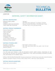
Engineers, superintendents, contractors, foremen, and laying crews will findmuch to guide them in the following specifications. This booklet will also beof help in determining pipe needs when ordering.Pipe DesignThe corrugated HDPE pipe design evolved over the last 40 years from primarilyan agricultural drainage product to a dominant product in the entiredrainage market. This 40-year evolution has brought about many changes inpipe design and materials. <strong>JM</strong> <strong>Eagle</strong>’s <strong>Eagle</strong> Corr PE is the culmination ofthis evolution. Some of the terms used in this installation manual are definedin Figure 1 below.Dual GasketsHeavy Duty Integral BellDual Crown CorrugationHydraulically Smooth InteriorFigure 1Some of these innovations, such as the heavy duty integral bell, are a resultof innovations in manufacturing technology which was necessitated by aneed to have more robust bells for watertight applications—an evolution othersare attempting by wrapping bands around the bell of the pipe and othertypes of reinforcements. Other innovations, such as the inline bell and spigot,reduce the amount of skill necessary for the contractor and ensure consistentinvert grade. These and many more innovations in this pipe design arehighlighted in the installation instructions to follow.<strong>EAGLE</strong> <strong>CORR</strong> PE INSTALLATION GUIDE5
Warranty<strong>JM</strong> <strong>Eagle</strong> warrants that its standard polyvinyl chloride (PVC), polyethylene(PE), conduit/plumbing/solvent weld and Acrylonitrile-Butadiene-Styrene(ABS) pipe products (“Products”) are manufactured in accordance with applicableindustry specifications referenced on the Product and are free fromdefects in workmanship and materials. Every claim under this warranty shallbe void unless in writing and received by <strong>JM</strong> <strong>Eagle</strong> within 30 days of thedate the defect was discovered, and within one year of the date of shipmentfrom the <strong>JM</strong> <strong>Eagle</strong> plant. Claims for Product appearance defects, however,must be made within 30 days of the date of the shipment from the <strong>JM</strong> <strong>Eagle</strong> plant. Proof of purchase with the date thereof must be presented to thesatisfaction of <strong>JM</strong> <strong>Eagle</strong> , with any claim made pursuant to this warranty.<strong>JM</strong> <strong>Eagle</strong> must first be given an opportunity to inspect the alleged defectiveProducts in order to determine if it meets applicable industry standards, ifthe handling and installation have been satisfactorily performed in accordancewith <strong>JM</strong> <strong>Eagle</strong> recommended practices and if operating conditionsare within standards. Written permission and/or a Return Goods Authorization(RGA) must be obtained along with instructions for return shipment to<strong>JM</strong> <strong>Eagle</strong> of any Products claimed to be defective.The limited and exclusive remedy for breach of this Limited Warranty shallbe, at <strong>JM</strong> <strong>Eagle</strong>’s sole discretion, the replacement of the same type, size andlike quantity of non-defective Product, or credits, offsets or combination ofthereof, for the wholesale purchase price of the defective unit.This Limited Warranty does not apply for any Product failures caused by user’sflawed designs or specifications, unsatisfactory applications, improperinstallations, use in conjunction with incompatible materials, contact withaggressive chemical agents, freezing or overheating of liquids in the Product,and any other misuse causes not listed here. This Limited Warranty also excludesfailure or damage caused by fire stopping materials, tread sealants, ordamage caused by the fault or negligence of anyone other than <strong>JM</strong> <strong>Eagle</strong> ,or any other act or event beyond the control of <strong>JM</strong> <strong>Eagle</strong> .<strong>JM</strong> <strong>Eagle</strong>’s liability shall not, at any time, exceed the actual wholesale purchaseprice of the Product. The warranties in this document are the only warrantiesapplicable to the Product and there are no other warranties, expressedor implied. This Limited Warranty specifically excludes any liability for general6 <strong>EAGLE</strong> <strong>CORR</strong> PE INSTALLATION GUIDE
damages, consequential or incidental damages, including without limitation,costs incurred from removal, reinstallation, or other expenses resulting fromany defect. IMPLIED WARRANTIES OF MERCHANTABILITY OR FITNESSFOR A PARTICULAR PURPOSE ARE SPECIFICALLY DISCLAIMED AND<strong>JM</strong> <strong>Eagle</strong> SHALL NOT BE LIABLE IN THIS RESPECT NOTWITHSTANDING<strong>JM</strong> <strong>Eagle</strong>’s ACTUAL KNOWLEDGE OF THE PRODUCT’S INTENDED USE.<strong>JM</strong> <strong>Eagle</strong>’s Products should be used in accordance with standards setforth by local plumbing and building laws, codes or regulations and theapplicable standards. Failure to adhere to these standards shall void thisLimited Warranty. Products sold by <strong>JM</strong> <strong>Eagle</strong> that are manufactured byothers are warranted only to the extent and limits of the warranty of themanufacturer. No statement, conduct or description by <strong>JM</strong> <strong>Eagle</strong> or itsrepresentative, in addition to or beyond this Limited Warranty, shall constitutea warranty. This Limited Warranty may only be modified in writingsigned by an officer of <strong>JM</strong> <strong>Eagle</strong> .<strong>EAGLE</strong> <strong>CORR</strong> PE INSTALLATION GUIDE7
1.0 Receiving and Handling Pipe Shipments1.1 InspectionInspect each pipe shipment with care upon arrival. Each pipe shipment iscarefully loaded at the factory using methods acceptable to the carrier. Thecarrier is then responsible for delivering the pipe as received from <strong>JM</strong> <strong>Eagle</strong> .All shipments include an adequate amount of lubricant for the pipe if necessary.IT IS THE RESPONSIBILITY OF THE RECEIVER TO MAKE CERTAINTHERE HAS BEEN NO LOSS OR DAMAGE UPON ARRIVAL.Check the materials, pipe, gaskets and fittings received against the bill oflading (tally sheet that accompanies every shipment) in accordance with thegeneral guidelines below, report any error or damage to the transportationcompany representative, and have proper notation made on the delivery receiptand signed by the driver. Present the claim in accordance with thecarrier’s instructions. Do not dispose of any damaged material. The carrierwill advise you of the procedure to follow in order to procure samples andreport the incident.1. MAKE OVERALL EXAMINATION OF THE LOAD. If the load is intact, ordinaryinspection while unloading should be enough to make sure pipehas arrived in good condition.2. IF LOAD HAS SHIFTED OR SHOWS ROUGH TREATMENT, THEN EACHPIECE MUST BE CAREFULLY INSPECTED FOR DAMAGE.3. CHECK THE TOTAL QUANTITIES OF EACH ITEM AGAINST THE TALLYSHEET (pipe, fittings, lubricant, etc.).4. ANY DAMAGED OR MISSING ITEMS MUST BE NOTED ON THE DELIV-ERY RECEIPT AND RETURNED TO THE TRANSPORTATION COMPANY.5. NOTIFY CARRIER IMMEDIATELY AND MAKE CLAIM IN ACCORDANCEWITH THEIR INSTRUCTIONS.6. DO NOT DISPOSE OF ANY DAMAGED MATERIAL. Carrier will notify youof the procedure to follow.7. SHORTAGES AND DAMAGED MATERIALS ARE NOT AUTOMATICALLYRESHIPPED. If replacement material is needed, reorder through yourdistributor and make them aware of the claim.8 <strong>EAGLE</strong> <strong>CORR</strong> PE INSTALLATION GUIDE
Figure 21.2 Unloading<strong>JM</strong> <strong>Eagle</strong>'s <strong>Eagle</strong> Corr PE is lightweight and may be unloaded by j Hand(for 18-inch diameter and smaller). k Conventional forklifts for compactshipping units, palletized bundles in a wood frame which may be used toship large orders of pipe. Exercise care to avoid impact or contact betweenthe forks and the pipe. The means by which <strong>Eagle</strong> Corr PE pipe are unloadedin the field is the decision and responsibility of the customer. Preferredunloading is in units using mechanical equipment such as forklifts,cranes, cherry pickers or front-end loaders with adequate forks and trained,competent operators and equipment rated to safely handle the load. Whenunloading units, the instructions below should be carefully followed. Removeonly one unit at a time.1. Follow OSHA Safety Requirements.2. Remove restraints from the top unit loads. These may be either tiedownstraps, ropes or chains with protection. Extreme caution must be usedwhen removing restraints from the shipment. The load may have shiftedand could fall from the truck.3. If there are boards across the top and down the sides of the load that arenot part of pipe packaging or secure the load from rolling off the truck,remove them.<strong>EAGLE</strong> <strong>CORR</strong> PE INSTALLATION GUIDE9
4. Use a forklift (or front-end loader equipped with forks) to remove eachtop unit one at a time from the truck. Remove back units first. Do notrun the forks too far under the unit as fork ends striking adjacent unitsmay cause damage, or push other units off the opposite side of truck.Do not let forks rub the underside of pipe to avoid abrasion.5. If a forklift is not available, a crane or front end loader may be used tounload the pipe. We recommend employing a spreader bar with syntheticstraps rated for the load. Lift 36-inch and larger pipe with a slingat two points along the length of the pipe. The straps should be placedapproximately 8 feet apart and looped under the load. Cables may beused in place of synthetic straps if they are protected by a rubber hosesleeve to prevent damage to the pipe.6. DO NOT:a) Handle units with chains or single cables.b) Attach cables to unit frames for lifting.c) Drop pipe or roll the pipe off the truck.d) Use loading forks or forklift directly on the inside of pipe.7. During the removal and handling, be sure that the units do not strikeanything.8. Units should be stored and placed on level ground. Units should beprotected by dunnage in the same way they were protected while loadedon the truck. The dunnage must support the weight of all units sothat pipe lengths do not carry the weight of the unit loaded above them.Units should not be stacked more than two high.9. Non-palletized pipe may be temporarily stockpiled on flat, clear area.10. To unload lower units, repeat the above unloading process (items 1through 9).10 <strong>EAGLE</strong> <strong>CORR</strong> PE INSTALLATION GUIDE
1.4 Gasket CareAll <strong>Eagle</strong> Corr PE pipe is manufactured with factory-installed gaskets.Keep them clean, away from oil, grease, excessive heat and electric motors,which produce ozone. It is advisable to keep gaskets protected from directsunlight and temperature changes to avoid cracking in prolonged exposurefor optimal performance. <strong>JM</strong> <strong>Eagle</strong> provides a gasket that is approved forsewer service with its standard product. Special gasket types may be availablefor applications where oil resistance is required. Be sure the correct ringis ordered.1.5 Loading Transfer TrucksUse trucks with long bodies so that pipe lengths do not overhang more than2 feet. Make certain truck bed is smooth, without cross-strips, bolt headsor other protrusions that could damage the pipe. Avoid sliding the pipe anddamaging it.Short-body trucks may be used if fitted with racks that properly support thepipe in the horizontal position. The rack shall support the pipe with supportsspaced every 3 feet or less along the pipe lengths. Pad the contact areas toavoid damage to the pipe.Figure 412 <strong>EAGLE</strong> <strong>CORR</strong> PE INSTALLATION GUIDE
1.6 Distributing Along the TrenchIn stringing out pipe, keep these points in mind:1. Line pipe as near to the trench as possible to avoid excessive handling.2. If the trench is open, it is advisable to string pipe on the side away fromexcavated earth wherever possible, so that the pipe can be moved easilyto the edge of the trench for lowering into position.3. If the trench is not yet open, find out which side the excavated earthwill be thrown, then string out on the opposite side (leave room forthe excavator).4. Place the pipe so as to protect it from traffic and heavy equipment.Also, safeguard it from the effect of any blasting that may be done.5. Direct sunlight may cause the exposed side of the pipe to heat up, creatinga bow in the pipe. Should this occur, the bow may be alleviatedby rotating the cool side toward the sun or by placing the pipe in theshade. Leaving pipe in palletized units minimizes bowing due to heatfrom the sun.6. It is normal practice to string pipe with bell ends pointing upgrade.Figure 5<strong>EAGLE</strong> <strong>CORR</strong> PE INSTALLATION GUIDE13
2.0 Trench Construction2.1 Working Ahead of the Pipe Laying CrewWhere soil and ground water conditions permit, long stretches of trench canbe opened ahead of pipe laying, so as to take full advantage of the easyhandling and speed of assembly of <strong>Eagle</strong> Corr PE sewer and storm drainpipe. However, as a general rule for most jobs, do not open the trench toofar ahead of pipe laying. Avoiding these long stretches of opened trench mayhelp with the economy of the project because:1. It may reduce or even eliminate pumping or sheeting.2. It minimizes the possibility of flooding the trench.3. It reduces caving caused by ground water.4. It helps avoid frozen trench bottom and backfill.5. It reduces hazards to traffic and workmen.On most jobs, it will be desirable to keep excavating, pipe laying and backfillingclose together.2.2 Curves in the TrenchThe trench may be curved to change direction or avoid obstructions withinthe limits of the curvature of the pipe as described below. Since the momentof inertia of <strong>Eagle</strong> Corr PE pipe is high, attempting to curve the pipe may bedifficult. If the pipe barrel cannot be curved, the joints may be deflected to amaximum of 1.5 degrees (or a radius of approximately 760 feet or a 6-inchoffset maximum). Offset and radius of curvature is based on a 19.8-footlength of pipe. To accomplish this, the pipe should be assembled in straightalignment and then, with the joint braced, the free end moved laterally usinga pry bar or other suitable means. Care should be taken not to exceed themaximum deflection allowed or damage the pipe with the machinery used.Abrupt changes in direction may be accomplished with fittings.14 <strong>EAGLE</strong> <strong>CORR</strong> PE INSTALLATION GUIDE
NOTICE: AVOID OVER-STRESSING THE BELL OR PIPE WALL (over-insertingthe joints, or exceeding the maximum deflection allowed) IN ORDER TOPREVENT POSSIBLE BREAKAGE AND/OR LEAKS.2.3 Trench WidthsIn general pipe diameter, backfill material, compaction equipment and nativesoils all influence the minimum trench width. Trench widths should be keptto a minimum to avoid excessive excavation cost. However, trench widthsmust be sufficient for adequate backfill compaction, compaction equipmentand safety equipment. The trench width at the ground surface may vary withand depend upon depth, type of soils and position of surface structures.The minimum clear width of the trench, sheeted or unsheeted, measured atthe spring-line of the pipe should be 1 foot greater than the outside diameterof the pipe. The maximum clear width of the trench at the top of the pipeshould not exceed a width equal to the pipe outside diameter plus 2 feet.This spacing will allow for proper compacting of the backfill to provide necessarysidewall support. If the above-defined trench widths must be exceededor, if the pipe is installed in a compacted embankment, pipe embedmentshould be compacted to a point of at least 2.5 pipe diameters from thepipe on both sides of the pipe or to the trench walls, whichever is less. Theminimum recommend trench widths are shown in Table 1. Please note thatthese trench widths are recommendations only and the does not supersederequirements specified by the project engineer.NOTICE: The trench width recommendations above are to help installersrealize the economies that may result from installation of <strong>Eagle</strong> Corr PE pipe over other materials, while maintaining adequate control over backfilling,compaction, and placement to limit long-term deflection.<strong>EAGLE</strong> <strong>CORR</strong> PE INSTALLATION GUIDE15
Table 1Nominal IDIN (mm)Minimum Trench widthsAverage ODIN (mm)minimum trench width 1IN (m)4 (100) 5 (120) 21 (0.5)6 (150) 7 (174) 23 (0.6)8 (200) 9 (231) 25 (0.6)10 (250) 11 (290) 27 (0.7)12 (300) 14 (363) 30 (0.8)15 (375) 17 (444) 34 (0.9)18 (450) 21 (529) 38 (1.0)24 (600) 28 (699) 46 (1.2)30 (750) 35 (880) 55 (1.4)36 (900) 42 (1055) 64 (1.6)42 (1050) 47 (1204) 71 (1.8)48 (1200) 54 (1367) 79 (2.0)60 (1500) 67 (1693) 95 (2.4)2.4 Trench DepthsDepth is governed by surface loads, earth loads and backfill material. A minimumof 12 inches depth of cover is recommended for diameters 48 inchesand smaller and a minimum of 24 inches for 60 inches diameter pipe.For more information on minimum and maximum burial depths and deflection,see Table 14 on page 57.2.5 Preparation of Trench BottomThe trench bottom should be smooth and free from stones greater than1.5 inches in diameter, large dirt clods and any frozen material. Excavationshould be provided so that the pipe is uniformly supported along its length.For details regarding the foundation for the trench bottom, pipe bedding andinitial backfill around the pipe, see Section 4 of the manual.16 <strong>EAGLE</strong> <strong>CORR</strong> PE INSTALLATION GUIDE
2.6 Trench Safety, Trench Boxes and SheetingTrenches can be dangerous and the contractor has the responsibility of ensuringthat all safety regulations and design requirements have been observedfor the protection of the workers and the public. OSHA requirementsshould always be followed when using a trench box.The length of the trench box should be suitable for the pipe length. The mosteffective trench configuration is the subtrench method as shown in Figure 6.This subtrench method is effective in maintaining the integrity of the backfilland compaction, while meeting safety requirements. The maximum recommendedsubtrench is 24 inches, as shown in Figure 6. Backfill and compactwithin the subtrench should be in accordance with the design specifications.The trench box can be pulled along the top of the subtrench without affectingthe pipe or the backfill.Trench box6" min.TrenchcenterlineNativeIN-SITU SoilInitial backfillmaterial placedand compactedper projectspecifications2"—0" subtrenchAlternateexcavationlineGeotextile(if necessary)Trench widthper project specificationFigure 6<strong>EAGLE</strong> <strong>CORR</strong> PE INSTALLATION GUIDE17
When sheeting is used, it should be left in place unless it is designed toprevent disturbing the soil adjacent to the pipe when pulled and removed.If heavy wooden sheeting has to be pulled, well-graded granular materialshould be placed on each side of the pipe for a distance of at least two pipediameters. The granular material should be compacted to at least 90 percentStandard Proctor Density.Whenever possible, sheeting and bracing should be installed so that the bottomof the sheeting extends no lower than the spring-line or 2 feet from thebottom of the pipe (whichever is less). When installed in this manner, pullingthe sheeting will minimize disturbance of the initial backfill material, whichprovides sidewall support for the pipe. If a trench box is used, it should bedesigned so that the backend of the sides do not extend below 2 feet abovethe bottom of the pipe. This will allow filling and compaction of the annularspace as the trench box is moved forward.It should be noted that OSHA standards change from time to time. In theevent any of these recommendations are in conflict with OSHA standardsor specific site conditions warrant alternative safety precautions, contact aqualified engineer.Figure 718 <strong>EAGLE</strong> <strong>CORR</strong> PE INSTALLATION GUIDE
3.0 Pipeline Construction3.1 InspectionPipe and fittings should be inspected for defects or damage prior to loweringinto the trench. Any defective, damaged or unsound pipe should be repairedor replaced and all foreign matter or soil should be removed from the interiorof the pipe and fittings, before lowering into the trench. If any corrugationsare damaged. See Section 1, “Receiving and Handling Pipe Shipments,” fora determination of pipe service ability.3.2 Lowering Pipe and Accessories into TrenchAll pipe, fittings, valves and accessories should be carefully lowered into thetrench using suitable equipment in such a manner as to prevent damageto pipe and accessories. PIPE AND ACCESSORIES SHOULD NEVER BEDROPPED OR DUMPED INTO THE TRENCH.DO NOT use chains or cables for lowering <strong>Eagle</strong> Corr PE into the trenchunless they are padded in some way to prevent damage to the pipe. We recommendusing nylon strap slings.3.3 Assembly of <strong>Eagle</strong> Corr PE <strong>Eagle</strong> Corr PE uses bell-and-spigot connections. It is imperative thatthe joint be assembled properly to ensure performance to expectations.Make certain that both the bell and spigot are clean and have no foreignmatter that could prevent an effective seal between the gasket and bell surfaces.<strong>Eagle</strong> Corr PE gasket rings are shipped on the spigot and wrappedwith a protective wrap to prevent loss or damage of the ring. (See Figure 8).Depending on the application, the pipe spigot may have two gaskets.<strong>EAGLE</strong> <strong>CORR</strong> PE INSTALLATION GUIDE19
Figure 8Important: If for any reason the gasket must be placed on the pipe inthe field, make sure that the gasket ring is seated flatly in the tapered corrugationgroove on the spigot end of the pipe. For a soiltight connection, placeone gasket ring in the outer tapered corrugation groove. For a watertightconnection (10.8 psi), place one gasket each in the inner and outer taperedcorrugation grooves. See Figure 9 for a picture of the spigot end piece of<strong>Eagle</strong> Corr PE watertight pipe with dual gaskets.Figure 920 <strong>EAGLE</strong> <strong>CORR</strong> PE INSTALLATION GUIDE
Joint Assembly1. Lower the pipe into trench by hand or use a nylon strap and excavatingequipment.2. Inspect the bell and remove foreign matter such as stones and dirt (ifany). Foreign matter lodged between the gasket and the bell sealing surfacecould cause a leak in the joint.3. Use a clean brush, cloth rag, sponge or gloved hand to lubricate bell witha thin layer of lubricant. Be sure to cover the full circumference4. Remove protective wrap from gasket(s).5. Clean spigot end of pipe.6. Use a clean brush, cloth rag, sponge or gloved hand to lubricate gasket(s).See Figure 10.7. Do not allow lubricated sections to contact dirt or backfill. Foreign mattercould stick to the surface and compromise joint integrity.8. Insert the spigot end into the bell.Note: Always push the spigot end into the bell end. Pushing the bell ontothe spigot may scoop dirt, backfill and/or foreign matter into the bell andcompromise the pipe joint.Figure 10<strong>EAGLE</strong> <strong>CORR</strong> PE INSTALLATION GUIDE21
Pipe Joint Homing MethodsPipe joint homing can be achieved by one of the following methods:1. Bar and Block Method2. Excavator Method3. Excavator & Sling MethodBar and Block MethodSmall 4-inch to 18-inch diameter <strong>Eagle</strong> Corr PE pipe can be assembled byusing the bar and block method.1. With the pipe trench bedding properly prepared and the pipe properlysupported, drive the steel bar into the trench bottom.2. Place a wood block into the bell end of the pipe. (The wood block protectsthe pipe against damage by the bar.)3. With the bar, push against the wooden block until the spigot is pushedinto the bell. Stop pushing together when the factory-applied stop markon the spigot is flush with the end of the bell. See Figure 11.Figure 11Excavator and Sling MethodExcavator and Sling Method can be used on all sizes of pipe, but is mostcommonly used for 24-inch and greater diameters of pipe.1. With the pipe trench bedding properly prepared, wrap a nylon slingaround the pipe. One pack-up point is typically used for pipe less than22 <strong>EAGLE</strong> <strong>CORR</strong> PE INSTALLATION GUIDE
4. Place a wooden block across installation stub.5. Push back of excavator bucket against block until the pipe is full insertedinto the bell and is homed. Caution should be exercised not to over homethe pipe.Figure 13CAUTION: While attempting assembly, be sure the pipe lengths are instraight alignment and not misaligned vertically or horizontally. Improperalignment will cause a difficult or impossible assembly. If pipe must be misalignedin line or grade, it can be done after assembly is completed. Suchmisalignment should not exceed 1.5 degrees at each joint. Also, note thatexcessive misalignment or an over-assembled joint can cause leaks.Figure 14Installation Stub Field Fabrication24 <strong>EAGLE</strong> <strong>CORR</strong> PE INSTALLATION GUIDE
Fabrication of an installation stub is necessary to prevent inadvertent damagewhile assembling the pipe joint. If the bell is not pushed on during theassembly process an installation stub is not necessary. An installation stubcan be fabricated on the job site in two ways.1. If a spigot of pipe (from the same diameter of pipe being assembled)is available, a short section of the spigot can be inserted into the belland used as an installation stub. At a minimum, this short section of thespigot will be cut in the valley of the fifth corrugation from the spigot endof the pipe.2. A second method of fabricating an installation stub uses a short sectionof pipe five full-size corrugations long. (Note: The outside diameterof the spigot corrugations are smaller than the outside diameter ofthe full size corrugations along the barrel of the pipe). Both ends of thepipe should cut in the valley of the corrugations. Fabricating this installationstub requires saw cutting a predefined width of the pipe (W) alongthe length of the short section of pipe (see Figure 15). The width of thesaw cut is dependent on the diameter of the pipe and is summarized inTable 2. Once the section of pipe is removed, the cut section can bepushed together and inserted into a bell.WWFigure 15<strong>EAGLE</strong> <strong>CORR</strong> PE INSTALLATION GUIDE25
Installation Stub Cut WidthsDiameter(s) In (mm)Width In (mm)4 – 6 (100 – 150) 2 (50)8 (200) 2.5 (65)10 – 12 (250 – 300) 4 (100)15 (375) 5 (125)18 (450) 6 (150)24 (600) 7.5 (190)30 – 42 (750 – 1050) 10 (254)48 – 60 (1200 – 1500) 12 (300)Table 2Field Cuts and Jointing PipeIt is easier and safer to cut pipe to the exact length before it is placed inthe trench. A hand saw with “cross cut” teeth is recommended for cutting<strong>Eagle</strong> Corr PE . Because of the unique design <strong>Eagle</strong> Corr PE , it is recommendedto cut the pipe between the corrugations. Simply measure therequired length from the pipe end and cut at the mid-point between the ribsas shown in Figures 16 and 17.Field cut hereFigure 16Note: If an abrasive saw is used to cut <strong>Eagle</strong> Corr PE pipe, safety gogglesshould be worn by the saw operator to protect eyes from pipe chips.26 <strong>EAGLE</strong> <strong>CORR</strong> PE INSTALLATION GUIDE
Figure 17When <strong>Eagle</strong> Corr PE must be field cut to fit a specific application, the followinginstructions will ensure proper performing joints:1. Remove the reduced spigot from the pipe (8-inch-diameter or larger).Cut in the center of the valley of the first full corrugation.2. Trim remaining polyethylene burrs from saw cut.Note: Failure to smoothly trim burrs may compromise joint integrity.3. Remove dirt and debris from the valley for the first corrugation at the cutend of pipe. (This is where gasket will be placed.)4. Remove gasket from plastic bag.5. Hold gasket with both hands so printing is facing you.6. Slide valley gasket into first corrugation valley, starting at the bottom sothat the gasket label is upright and readable from the cut end of the pipe.Note: It is easier to place gasket in the valley at the bottom of the pipeand pull up to conform to the valley. (See Figure 18.)7. Slide gasket into first corrugation valley by hand.8. Ensure printing on gasket is face-up and toward spigot end of pipe.<strong>EAGLE</strong> <strong>CORR</strong> PE INSTALLATION GUIDE27
Gasket label should be upright andreadable from cut end of pipeField cut end of pipeClean corrugation valleybefore placing gasket on pipeFigure 18Note: Gasket shown for illustrative purposes. Actual gasket size and shapemay vary.To assemble <strong>Eagle</strong> Corr PE use only the <strong>JM</strong> <strong>Eagle</strong> approved lubricantsupplied, based on normal conditions. Extra lubricant needed for adverseconditions must be ordered separately. Lubricant is supplied for pipe andfittings based on the number of spigot ends involved.3.3.1 Lubricant RequirementsThe following table gives the number of pipe joints that can be assembledusing a 1-quart container of lubricant for <strong>Eagle</strong> Corr PE pipe. See Table 3.28 <strong>EAGLE</strong> <strong>CORR</strong> PE INSTALLATION GUIDE
PIPE SIZEjoints/1 lb of lubricantINCHESMM8 200 1510 250 1212 300 915 375 618 450 4+24 600 430 750 3+36 900 342 1050 2+48 1200 260 1500 1+Table 33.4 Catch Basin and manhole StructuresStructures vary by locality with brick, concrete blocks, pre-cast concrete andPVC units most commonly being used. Catch basins are typically used tocollect surface runoff from developed parcels of land, while manhole structuresare typically used to change pipe size, pipe material, direction, gradeand elevation. For commercial developments, PVC or HDPE catch basins arepreferred. Concrete does not bond to HDPE pipe.Regardless of the type of structure or type of pipe being connected to,there are basic engineering areas of concern: differential settlement betweenthe pipe and the structure, and the connection between the pipeand structure. Addressing these two concerns with proper installationtechniques helps ensure that the system will meet long term expectations.Proper installation techniques to address these concerns are addressed inthe next few paragraphs.3.4.1 Transitions to Manholes, Catch Basins and<strong>EAGLE</strong> <strong>CORR</strong> PE INSTALLATION GUIDE29
and other StructuresThe connection between the any type of pipe and structures is also critical tomeeting long-term expectations. Poor connections between pipe and structuresmay allow soil to infiltrate into the structure and water to exfiltrate outof the structure. This movement of materials creates voids and contributesto sink holes and differential settlement of the structure. The type of connectionrequired depends onsite conditions that include water table, systemsurcharge and in-situ soils. Additionally the types of connections may be dictatedlogistical constraints that may require field fabrication of a reliable joint.The following paragraphs describe five of the most commonly recognizedmethods of connecting pipe to structures for stormwater sanitary sewer andirrigation applications.Soil-TightThe grouted field fabricated connection is a soil-tight connection. This connectionis illustrated in Figure 20. This type of connection is one of the simplestand most reliable connection. The corrugations grouted with a nonshrinkcemetious grout form a soil-tight seal with the corrugations lockinginto the grout. This connection is field fabricated and is soil tight.Non-shrink groutManhole<strong>Eagle</strong> Corr PE pipeType “A”—Soil Tight:<strong>Eagle</strong> Corr PE w/Non-Shrink grout(field fabricated)Figure 20WaterTight<strong>EAGLE</strong> <strong>CORR</strong> PE INSTALLATION GUIDE31
Cement does not adhere to HDPE. Therefore, gaskets are inserted into thevalley of the corrugations passing through the structure wall. The valleygasket will serve as a waterstop. The pipe and gasket are then grouted inplace with a non-shrink cementious grout. Special attention must be givento ensuring the grout is well placed. A detail of this connection is shown inFigure 21.Non-shrink groutManhole<strong>Eagle</strong> Corr PEcorrugated pipeType “B”—Watertight Capable:<strong>Eagle</strong> Corr PE w/Non-Shrinkgrout & valley gasket(s)(field fabricated)Two valley gasketsfor 12" & 15" pipesingle valley gasketfor 18"—60"Figure 21Booted Manhole ConnectionsThose are also used for drainage applications and are typically the preferredmethod for sanitary sewer applications. The booted manhole connection isused for making flexible boot connections to a structure. This Type “C” connectionis shown in Figure 22. The booted connection requires a prefabricateda smooth manhole adaptor, which has a smooth exterior. This smoothexterior enables the boot to have flat surface to seal against. To order thesmooth manhole adaptor from <strong>JM</strong> <strong>Eagle</strong> , specify the pipe diameter.32 <strong>EAGLE</strong> <strong>CORR</strong> PE INSTALLATION GUIDE
Flexible connector(Kor-N-Seal)ManholeFabricated HDPEtriple wall manholeadaptorType “C”—Watertight:<strong>Eagle</strong> Corr PE w/fabricatedHDPE triple wall manhole& Kor-N-Seal (or equal)AFigure 22When ordering the flexible boot connection refer to the Smooth ManholeAdaptor outside diameter listed in Table 4. Contact the flexible boot connectionsupplier for product recommendations.PIPE SIZEMANHOLE ADAPTORO.D.Table 4INCHES MM INCHES MM8 200 9.4 239.110 250 11.7 297.512 300 14.6 371.2015 375 17.8 452.4018 450 21.1 536.3024 600 27.8 706.4030 750 35.2 893.1036 900 42.1 1,068.4042 1050 48.2 1,224.6048 1200 54.6 1,387.2060 1500 67.5 1,714.80A-Lok Style Manhole ConnectionsWhere manholes are manufactured with A-Lok's use the “smooth” manholeadaptor is recommended. This Type “D” connection is shown in Figure 23.<strong>EAGLE</strong> <strong>CORR</strong> PE INSTALLATION GUIDE33
Watertight connector (A-Lok )ManholeType “D”—Watertight:<strong>Eagle</strong> Corr PE w/fabricatedHDPE triple wall manholeadaptor & A-Lok (or equal)AFabricated HDPEtriple wall manholeadaptorFigure 23The A-Lok should be sized based on the Smooth Manhole Adaptor outsidediameter. Contact A-Lok for the recommended A-Lok product.Booted Field Fabricated ConnectionTo field fabricate a booted watertight field connection, a valley gasket isplaced on the pipe and a full corrugation bell is placed on the pipe to forma smooth exterior. The rubber boot is then tightened on to the bell outsidediameter. See Figure 24.Flexible connector(Kor-N-Seal)ManholeFull sizecorrugation bellType “E”—Watertight:<strong>Eagle</strong> Corr PE w/Gasket FullO.D. Bell & Kor-N-Seal or equal(field fabricated)AFigure 244.0 Pipe embedment34 <strong>EAGLE</strong> <strong>CORR</strong> PE INSTALLATION GUIDE
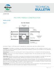
Understanding flexible conduit terminology is essential for the installer. Thesoil class and density realized in the bedding, haunching and initial backfill,as well as the manner and care with which they are placed, are importantfactors in achieving a satisfactory installation of a flexible conduit. Overdeflection,when it occurs, is invariably the result of improper compactionin the haunching area. Figure 25 is an illustration of a typical trench with allmajor regions identified, as they will be addressed in the following sections.Excavatedtrench widthFinal blackfillFinal blackfillNative IN-SITUsoil6" min.Initial blackfillEnbedment4" for 12"—24" pipe6" for 30"—60" pipeSpringlineHaunchBeddingFoundation(if required)Figure 254.1 PREPARATION OF THE TRENCH BOTTOMThe trench floor should be constructed to provide a firm, stable and uniformsupport for the full length of the pipe. This can be accomplished by bringingthe entire trench floor to a level grade to permit proper joint assembly, align-<strong>EAGLE</strong> <strong>CORR</strong> PE INSTALLATION GUIDE35
ment, and support. Portions of the trench that are excavated below gradeshould be returned to grade and compacted as required to provide propersupport. If the native trench soil is not suitable for the pipe bedding, thetrench should be over excavated and refilled with suitable foundation materialas specified by the engineer. A cushion of acceptable bedding materialshould always be provided between any hard foundation and the pipe.Large rocks, boulders, and stones should be removed to allow a minimumof 4 inches of soil cushion on all sides of the pipe and accessories.4.2 TRENCH EXCAVATIONThe minimum width of a trench to insure the proper installation of a buriedconduit depends on the pipe diameter, embedment material and compactionrequirements. Trench widths for small diameter pipes are typically determinedby standard excavator bucket sizes. Trenches that are too narrow do not allowfor the proper amount and compaction of embedment material in the haunchzones, while trenches that are too wide result in unnecessary costs. Recommendedminimum trench widths per ASTM D2321 are shown in Table 5.Table 5Nominal IDIN (mm)Minimum Trench widthsAverage ODIN (mm)minimum trench width 1IN (m)4 (100) 5 (120) 21 (0.5)6 (150) 7 (174) 23 (0.6)8 (200) 9 (231) 25 (0.6)10 (250) 11 (290) 27 (0.7)12 (300) 14 (363) 30 (0.8)15 (375) 17 (444) 34 (0.9)18 (450) 21 (529) 38 (1.0)24 (600) 28 (699) 46 (1.2)30 (750) 35 (880) 55 (1.4)36 (900) 42 (1055) 64 (1.6)42 (1050) 47 (1204) 71 (1.8)48 (1200) 54 (1367) 79 (2.0)60 (1500) 67 (1693) 95 (2.4)1Minimum trench width per ASTM D2321 = greater of OD+16" or 1.25×OD+12".4.3 PIPE LAYING36 <strong>EAGLE</strong> <strong>CORR</strong> PE INSTALLATION GUIDE
Proper implements, tools and equipment should be used for placement ofthe pipe in the trench to prevent damage. Avoid dropping pipe and accessoriesinto the trench, as this may cause damage that is not easily detected.Additional handling instructions may be sought from our product installationguides or by contacting <strong>JM</strong> <strong>Eagle</strong> . In general, pipe laying should begin atthe lowest point and work toward manholes, service branches or clean-outs.Pipe bells can be laid in either direction, upstream or downstream withoutany significant hydraulic loss. However, common practice is to lay the bellsin the direction of work progress to ease installation. Additionally, by insertingthe spigot into the bell rather than pushing the bell over the spigot, therisk of soil or rubble being scooped under the gasket is reduced. If pipe layingis interrupted or halted, the exposed ends of the pipeline should beclosed to prevent the entrance of trench water, mud and foreign matter.4.4 FoundationA foundation is required when the trench bottom is unstable. Any foundationthat will support a rigid pipe without causing loss of grade or flexural breakingwill be more than adequate for <strong>Eagle</strong> Corr PE pipe.In cases where muck, peat or other soft material form the foundation, there isa potential for the pipe to settle and loose grade. In cases where rock, rockprotrusions or unyielding material form the foundation, there is a potential fora point load on the pipe or fittings. Both of these cases may affect hydraulicsand/or structural integrity of the system. It is recommended the trench bottombe over excavated and replaced with a suitable foundation, as specified bythe design or geotechnical engineer when these cases exist.4.5 BeddingBedding is required primarily to bring the trench bottom up to grade. Beddingmaterials should be placed to provide uniform longitudinal support under thepipe to prevent low spots. Blocking should not be used to bring the pipeto grade. Under normal circumstances, a bedding of 4 inches to 6 inchescompacted is of sufficient thickness for the bedding. The middle portion ofthe bedding (equal to one-third of the pipe's outside diameter) should be<strong>EAGLE</strong> <strong>CORR</strong> PE INSTALLATION GUIDE37
loosely placed to provide uniform support at the invert. Acceptable beddingmaterials include Class I, II, or III materials as defined in Table 6.If the native in-situ soil is comprised of fine grain soils and migration of thosesoils into the bedding material is anticipated, precautions should be takento eliminate or reduce the potential for soil migration. Acceptable methodsto minimize the potential for soil migration include, but are not limited to,nonwoven geotextile layer, use of acceptable bedding material with fines thatfill potential migration sites or other acceptable method to avoid compromisingthe trench backfill materials as specified by the engineer.Bell holes are used to maintain the grade of the pipe in cases where the pipefitting or coupler is greater than the outside diameter of the pipe. Properlyformed bell holes should not be over excavated and should provide uniformlongitudinal support for the pipe.4.6 Initial BackfillInitial backfill is critical since it provides support to the pipe to resist soil and liveloads. Initial backfill begins from the bottom of the pipe to a level of 6 inchesabove the top of the pipe. This material and minimum required compactionlevel should be on the construction plans and will take precedence on theproject site. Provided the plans meet minimum recommendations, backfillingshould follow trench excavation pipe assembly as closely and safely aspossible. Backfilling after pipe assembly eliminates the possibility of liftingthe pipe from grade due to flooding of an open trench, avoids shifting pipeout of line by cave-ins, and in cold weather lessens the possibility of backfillmaterial's becoming frozen.Placement of the initial backfill is a critical part of the installation operation.Typically, backfill material is placed in the center of the pipe allowing materialto fall on each of the pipes to keep soil pressure evenly distributed. Evendistribution of soil pressure during the initial backfill operation keeps thepipe aligned in the trench. In-situ or local material may be acceptable forbackfill, however, it is necessary that locally available material meet the soilclassifications outlined in Table 6. Minimum compaction levels, lift depthsand backfill material quality requirements are shown in Table 6 as well.38 <strong>EAGLE</strong> <strong>CORR</strong> PE INSTALLATION GUIDE
PIPE BEDDING, BACKFILL AND EMBEDMENT MATERIALDescriptionASTM ASTM AASHTO M145D2321 (1) D2487 (1) NotationMin. Std.Proctor Density (%)LiftPlacementDepth (5)Clean manufactured crushed rock, angularwith particle faces fractured. Angular crushedstone or rock, crushed gravel, crushed slag,stone/sand mixtures with ≤ 12% fines.I N/A — Dumped 18" (0.5m)Clean, coarse-grained soils, gravels, cleangravels, gravel/sand mixtures; Well-gradedsands, gravelly sands.IIGW (2) ,GP, SW,SPA1, A3 85% 12" (0.3m)Coarse-grained soils with fines, gravels withfines, clean sands, sands with fines, sandy orgravelly fine-grained soils.IIIGM (3) ,GC, SM,SCA-2-4, A-2-5, A-2-6, orA-4, or A-6 w/≤30%retained on #200 sieve90% 9" (0.2m)Fine grained soils, silts and clays, inorganicfine-grained soils; inorganic silts and very finesands, rock flour, silty or clayey fine sands,silts with slight plasticity.IV ML, CLA-2-7 or A-4 or A-6 w/≥30% retained on #200sieveN/R (4) N/RInorganic silts and clays, fine sandy or siltysoils; organic or highly organic soils; organicsilts and organic silty clays of low plasticity;organic clays of medium to high plasticity,organic silts; peat and other high organic soils.VMH, CH,OL, OH,PTA5, A7 N/R N/RTable 6<strong>EAGLE</strong> <strong>CORR</strong> PE INSTALLATION GUIDE39
GeneralRecommendationsand RestrictionsFoundationRecommendations for Installation and Use of Soils and Aggregatesfor Foundation, Embedment and Backfill.Soil class as defined in table 6Class IA Class IB class II class III Class iv-aDo not use whereconditions may causemigration of finesfrom adjacent soiland loss of pipesupport. Suitablefor use as a drainageblanket andunderdrain in rockcuts where adjacentmaterial is suitablygraded.Process materials asrequired to obtaingradation which willminimize migrationof adjacent materials.Suitable for use asdrainage blanketand underdrain.Where hydraulicgradient exist checkgradation to minimizemigration. “Clean”groups suitablefor use as drainageblanket andunderdrain.Do not use wherewater conditions intrench may causeinstability.Obtain geotechnicalevaluation ofprocessed material.May not be suitableunder high earth fillsand surface appliedloads or under heavyvibratory compactorsand tampers. Do notuse where waterconditions in trenchmay cause instability.Suitable asfoundation andfor replacingover-excavated andunstable trenchbottom as restrictedabove. Install andcompact in 6-inchmaximum layers.Suitable asfoundation andfor replacingover-excavatedand unstable trenchbottom. Install andcompact in 6-inchmaximum layers.Suitable asfoundation andfor replacingover-excavatedand unstable trenchbottom as restrictedabove. Install andcompact in 6-inchmaximum layers.—Suitable only inundisturbedconditions andwhere trench is dry.Remove all loosematerial and providefirm, uniform trenchbottom beforebedding is placed.40 <strong>EAGLE</strong> <strong>CORR</strong> PE INSTALLATION GUIDE
Suitable only in drytrench conditions.Install and compact in6-inch maximumlayers. Level final gradeby hand. Minimumdepth 4 inches(6 inches of rock cuts).Suitable as restrictedabove. Install andcompact in 6-inchmaximum layers.Levelfinal grade by hand.Minimum depth4 inches (6 inches inrock cuts).Install and compact in6-inch maximum layers.Level final gradeby hand. Minimumdepth 4 inches(6 inches in rock cuts).Suitable only in drytrench conditions andwhen optimum placementand compactioncontrol is maintained.Install and compact in6-inch maximum layers.Level final grade byhand. Minimum depth4 inches (6 inches inrock cuts).Suitable as restrictedabove. Install in 6-inchmaximum layers.Level final grade byhand. Minimum depth4 inches (6 inchesin rock cuts).BeddingSuitable as restrictedabove. Install andcompact in 6-inchmaximum layers.Work in around pipeby hand to provideuniform support.Suitable as restrictedabove. Install andcompact in 6-inchmaximum layers.Work in around pipeby hand to provideuniform support.Install and compact in6-inch maximumlayers. Work in aroundpipe by hand to provideuniform support.Suitable only in drytrench conditions andwhen optimum placementand compactioncontrol is maintained.Install and compact in6-inch maximum layers.Work in aroundpipe by hand to provideuniform support.Suitable as restrictedabove. Install in 6-inchmaximum layers. Workin around pipe byhand to provideuniform support.HaunchingSuitable as restrictedabove. Install andcompact to a minimumof 6 inches abovepipe crown.Suitable as restrictedabove. Install andcompact to a minimumof 6 inches abovepipe crown.Install and compact toa minimum of 6 inchesabove pipe crown.Suitable as restrictedabove. Install andcompact to aminimum of 6 inchesabove pipe crown.Suitable as restrictedabove. Install to aminimum of 6 inchesabove pipe crown.Initial BackfillCompact as requiredby the engineer.Compact as requiredby the engineer.Compact as requiredby the engineer.Suitable as restrictedabove. Compactas required by theengineer.Notes for Table 6:Compact as requiredby the engineer.Final BackfillTable 7Note: See section 4.8.5 for clarification Class IV-A materials as embedment material for flexible conduits.<strong>EAGLE</strong> <strong>CORR</strong> PE INSTALLATION GUIDE41
1. See ASTM D 2321 or D2487 for detailed description and classificationof material.2. Also includes materials that begin with SW, SP, GW, GP and less than orequal to 12 percent fines.3. GM, GC, SM, SC or any soil beginning with one of these symbols containing> 12 percent passing #200 sieve; CL, ML or any soil beginning withone of these symbols with less than or equal to 12 percent retained on#200 sieve.4. Not recommended for pipe applications. Some Class IV material may beused under special circumstances and under the direct supervision of adesign or geotechnical engineer.5. Layers should not exceed half the pipe diameter. Layer heights may needto be reduced to accommodate compaction methods.As with the bedding, it is important to prevent the migration of soils. Themigration soil between bedding and initial backfill and between the initialbackfill can affect the structural integrity of the installed system. If differentmaterials are used or there is the potential for soil migration, precautionsuch as nonwoven geotextile layer, use of acceptable bedding material withfines that fill potential migration sites, or other acceptable method to avoidcompromising the trench backfill materials as specified by the engineershould be taken.4.7 Haunching42 <strong>EAGLE</strong> <strong>CORR</strong> PE INSTALLATION GUIDE
Figure 26The haunching area is the most important in terms of limiting the deflectionof a flexible pipe. The haunch area is illustrated in Figure 25. The haunchingshould be placed in 4- to 6-inch lifts and compacted in accordance withTable 8. Because of the shape of the pipe and space restrictions in thetrench, special care must be taken to fill any voids and obtain propercompaction in the haunch area. Figures 27 and 28 illustrate correct andincorrect initial backfill placement in the haunch area.<strong>EAGLE</strong> <strong>CORR</strong> PE INSTALLATION GUIDE43
Correct backfillCorrect backfillUse board or othertamping device to placeand compact backfillunder Use board haunch or other area.tamping device to placeand compact backfillunder haunch <strong>Eagle</strong> Corr area. PEWell placedinitial backfill in<strong>Eagle</strong> Corr PEhaunchingareaWell placedinitial backfill inhaunchingareaFigure 27Incorrect backfillIncorrect backfillVoid and low compactionin haunch area.Void and low compaction<strong>Eagle</strong> Corr PEin haunch area.Poorly placedinitial backfill in<strong>Eagle</strong> Corr PEhaunchingareaPoorly placedinitial backfill inhaunchingareaFigure 284.8 EMBEDMENT MATERIALSMaterials suitable for foundation and embedment are classified in the Tables6 and 7. They include a number of processed materials plus soil typesdefined according to the Unified Soil Classification System in ASTM D2487,“Standard Method for Classification of Soils for Engineering Purposes.”Table 7 provides recommendations on the installation and use based onclass of soil or aggregates and location within the trench. It is important toengineer all materials used in the pipe trench to work together and with thenative material surrounding the trench.44 <strong>EAGLE</strong> <strong>CORR</strong> PE INSTALLATION GUIDE
Figure 294.8.1 CLASS IA MATERIALSClass IA materials provide the maximum stability and pipe support for agiven density because of the angular interlocking of the material particles.With minimum efforts, these materials can be installed at relatively high densitiesover a wide range of moisture contents. These materials also haveexcellent drainage characteristics that may aid in the control of water. Thesesoils are often desirable as embedment in rock cuts where water is frequentlyencountered. On the other hand, when ground water flow is anticipated,consideration should be given to potential migration of fines fromadjacent materials into the open graded Class IA materials.4.8.2 CLASS IB MATERIALSThese materials are produced by mixing Class IA and natural or processedsands to produce a particle-size distribution that minimizes migration fromsurrounding soils that may contain fines. They are more widely graded thanClass IA and thus require more compaction effort to achieve the minimumdensity specified. When these materials are properly compacted, these soilsexhibit high stiffness and strength, and depending on the amount of fines,may be relatively free draining.4.8.3 CLASS II MATERIALS<strong>EAGLE</strong> <strong>CORR</strong> PE INSTALLATION GUIDE45
When Class II materials are compacted they provide a relatively high levelof pipe support. In most respects, they all have the desirable characteristicsof Class IB materials when widely graded. However, open-graded groupsmay allow for migration and the sizes should be checked for compatibilitywith the native trench materials. Typically, Class II materials consist ofrounded particles and are less stable than the angular materials of Class IAand IB, unless they are confined and compacted.4.8.4 CLASS III MATERIALSThese materials provide less support for a given density than Class I orClass II materials. High levels of compactive effort are required if moisturecontent is not controlled. These materials will provide reasonable supportonce proper compaction is achieved.4.8.5 CLASS IV-A MATERIALSClass IV-A materials are not recommended as suitable embedment materialand must be carefully evaluated by a geotechnical engineer before use.The moisture content of the materials must be near optimum to minimizecompactive effort and achieve the required density. Properly placed andcompacted, these soils can provide reasonable levels of pipe support.However, these materials may not be suitable under high fills, surfaceapplied dynamic loads, or under heavy vibratory compactors and tampers.These materials should be avoided if water conditions in the trench maycause instability and result in uncontrolled water content.4.9 Final BackfillThis portion of the backfill begins 6 inches above the pipe (or from the initialbackfill) to finished grade elevation. In cases where paving, sidewalks or othersimilar structures are planed, compaction of the final backfill is critical toprevent settling. However, if no such structures are anticipated, compactionof the final backfill is not as critical since it does not contribute to the structuralintegrity of the pipe system. The final backfill above the initial backfill materialhas no effect, except for weight, on flexible pipe performance.46 <strong>EAGLE</strong> <strong>CORR</strong> PE INSTALLATION GUIDE
Unless otherwise specified, trenches under pavements, sidewalks or roadsshould be backfilled and compacted to 90-percent density, as determinedby the American Association of Highway and Transportation Officials MethodT99 for State Compaction and Density of Soils. Recommendation on the useand precaution for use of rolling, vibratory and hydro hammers is found inSection 4.10.2.Unless specified, other trenches may be backfilled without controlledcompaction in the final backfill. Additional backfill material should be supplied,if needed, to completely backfill the trenches or to fill depressions caused bysubsequent settlement.The trench and final backfilling should be carefully inspected to detect andremove any objectionable material such as large stones, frozen clumps ofsoil, bricks, etc., which may have fallen into the trench and be punchedthrough the initial backfill damaging the pipe.Figure 304.10 Compaction Methods and Equipment<strong>EAGLE</strong> <strong>CORR</strong> PE INSTALLATION GUIDE47
Selection of proper compaction equipment depends on the desired densityand type of material being compacted. Crushed stone, sands and gravelsare more easily compacted when vibratory equipment is used to transfercompaction energy. Highly plastic materials such as Class III and IV materialsrequire moisture control plus and a higher amount of compaction energyinduced by kneading and impact forces. Jumping jacks and walk-behindvibratory rollers are suitable for most classes of backfill materials, providedmoisture content is controlled.Crushed stone is usually not compacted. However, care must be taken toensure the material is properly placed in the pipe haunch zone. Typically,using a shovel to knife the material in the haunch area provides suitablebackfill support. Additionally, studies have shown that wetting the crushedstone reduces the friction between the fractured faces and improves in placestrength of the material.Figure 314.10.1 Hand Compaction in Haunch AreaIt is the discretion of the contractor (or design engineer) to determine the bestmethod to achieve required compaction in the haunch area.Tamping bars have been successfully used to compact the backfill in thepipe haunch zone.4.10.2 Mechanical Tampers48 <strong>EAGLE</strong> <strong>CORR</strong> PE INSTALLATION GUIDE
Care should be taken to avoid contact between the pipe and compactionequipment. Compaction of the embedment material should generally bedone in such a way so that the compaction equipment is not used directlyabove the pipe until sufficient backfill has been placed to ensure that the useof compaction equipment will not damage or deflect the pipe.When hydro-hammers are used to achieve compaction, they should not beused within 4 feet of the top of the pipe and then, only if the embedmentmaterial density has been previously compacted to a minimum 85 percentProctor density.4.10.3 Water-JettingThe introduction of water under pressure to the embedment material is notto be used to compact the embedment material.4.10.4 Compaction Equipment SelectionTable 8 illustrates a selection guide for compaction equipment.PropertyMinimum %CompactionEffortRequiredEquipmentTypeMoistureControlSoil Classification (1)Class I Class II Class III Class IVDumped 85% 90% 95%Low Moderate High Very HighHand Knifingin Haunch,Vibratory, ImpactNoneVibratory,ImpactNoneImpactNear optimumto minimizecompaction effortImpactNear optimumto minimizecompaction effortTable 8Notes:1. Soil classes defined in Table 6.2. See ASTM D2321 for a complete definition.4.11 MIGRATION<strong>EAGLE</strong> <strong>CORR</strong> PE INSTALLATION GUIDE49
In soils where ground water fluctuations occur, coarse or open-gradedmaterial placed adjacent to a finer material may be infiltrated by those fines.Such hydraulic gradients may arise during trench construction when waterlevels are being controlled by various pumping or well-pointing methods, orafter construction when permeable under drain or embedment materialsact as a “French” drain under high groundwater levels. Downward percolationof surface water may carry fine materials down into more coarse, opengradedbedding materials if the trench is not properly designed and constructed.The gradation and relative particle size of the embedment andadjacent materials must be compatible in order to minimize migration. As ageneral precaution, it is recommended that if significant groundwater flowis anticipated, avoid placing coarse, open-graded materials adjacent tofiner materials, unless methods are employed to impede migration, such asthe use of an appropriate stone filter or fabric along the boundary of incompatiblematerials.4.12 Parallel pipe installationStorm sewer conduits and underground drainage systems can be installed inparallel pipe configurations provided that the haunch zones are compactedwith the proper amount and type of embedment material. Class I, II, andIII materials are suitable for foundation and embedment. Minimum spacingbetween parallel pipes shall meet the minimum criteria set forth in Table 9.Parallel PipeInstallation Minimum SpacingNominal IDIN (mm)Minimum spacingIN (mm)ID 24 (600)ID/2Table 950 <strong>EAGLE</strong> <strong>CORR</strong> PE INSTALLATION GUIDE
I.D.I.D.MinimumspacingFigure 325.0 Minimum and maximum BURIAL DEPTH RECOMMENDATIONS5.1 Burial DepthsMaximum and minimum burial depths are determined by the type of initialbackfill material and compaction level (assuming a suitable foundationand bedding). Assuming the plans meet the initial backfill and compactionrequirement of Table 7 the construction plans should take precedence.Any discrepancies should be brought to the attention of the design engineer.5.1.1 Minimum CoverIn addition to the minimum cover height requirements, an extra foot oftemporary cover is recommended where heavy-duty construction equipmentmay travel over the pipe during the construction phase of the project.For H-25 traffic loads, a minimum cover of 12 inches, measured from thetop of the pipe to the top of rigid pavement sections or the bottom of flexiblepavement sections, is recommended for pipe diameters 48 inches and less.For H-25 traffic loads, a minimum cover of 24 inches, measured from thetop of the pipe to the top of rigid road surfaces or the bottom of flexibleroad surfaces, is recommended for 60-inch pipe. See Table 10 for details.Minimum covers may be reduced in areas with no or infrequent light traffic,provided flotation is not a concern and the design has been reviewed byan engineer.<strong>EAGLE</strong> <strong>CORR</strong> PE INSTALLATION GUIDE51
minimum cover heightsnominal ID in (mm)minimum cover ft (m)ID
The information contained herein describes the maximum allowable coverheight for <strong>Eagle</strong> Corr PE (Dual Wall). These recommendations addressmaximum burial depths for pipe meeting the requirements of AASHTO M252Type S, AASHTO M294 Type S, ASTM F2306 and ASTM F2648. This analysisis based on the design method developed by the Plastic Pipe Institute.The PPI design method is based on the actual pipe corrugation profile,which is conservative as evidenced by a long history of analytically predictedburial depths matching successful field installations.5.3 Maximum Cover Height AnalysisThe type and compaction of backfill around the pipe significantly influencethe maximum burial depth. The influence of the backfill and compaction isillustrated in Table 11, which was developed assuming the pipe is installedin accordance with ASTM D2321. These maximum cover height recommendationsassume the native soil is of adequate strength and is suitable forinstallation. Additionally, the calculations assume no hydrostatic load andsoil density of 120 pounds per cubic feet.Figure 335.4 Pipe Properties54 <strong>EAGLE</strong> <strong>CORR</strong> PE INSTALLATION GUIDE
Key pipe profile properties that influence the performance of the soil/pipestructure interaction include the moment of inertia of the profile (I), distancefrom the inside diameter to the neutral axis (c), and the section area of alongitudinal profile section (As). Pipe stiffness (PS) is also important criteria.The minimum pipe stiffness, defined by AASHTO was used for this analysis.These key properties are summarized in Table 12.section property summarynominalinsidediameter(IN)outsidediameter(IN)pipestiffness,PS (PSI)crosssectionalarea, as(in ˆ 2/in)distancefrominsidediameter toneautralaxis, c (in)moment ofinertia, I(in ˆ 4/in)pitch(IN)4.0 4.7 50 0.076 0.14 0.0012 0.656.0 6.9 50 0.122 0.19 0.0037 0.788.0 9.1 50 0.146 0.28 0.0085 0.9710.0 11.4 50 0.180 0.33 0.0171 1.2912.0 14.3 50 0.183 0.47 0.0366 1.9415.0 17.5 42 0.222 0.51 0.0549 2.5918.0 20.8 40 0.244 0.58 0.0824 3.1024.0 27.5 34 0.330 0.72 0.1593 3.1030.0 34.6 28 0.370 0.95 0.3118 3.8836.0 41.5 22 0.410 1.12 0.4986 5.1742.0 47.4 20 0.448 1.18 0.5531 5.1748.0 53.8 18 0.498 1.21 0.6551 5.1760.0 66.7 14 0.660 1.44 1.2766 7.76Table 12Note: Section property data is considered conservative, however, propertiesmay change based on actual production dimensions.5.5 Construction and Paving Equipment Loads<strong>EAGLE</strong> <strong>CORR</strong> PE INSTALLATION GUIDE55
The design live load for the pipe is typically H-25 as defined by AASHTO.Some construction and paving equipment is not as heavy as an H-25load. The vehicle load (surface pressure), backfill material and cover heightall influence the allowable construction load. For the minimum backfillcompaction and temporary construction loads, Table 13 illustrates allowableminimum cover heights.Minimum Temporary and Construction CoverSurface PressureInduced byConstructionVehicle (psi)Temporary Minimum Cover forRespective Diameters4" to 48"60"Diameter Pipe (1) Diameter Pipe (1)75 9-inchs 12-inches50 6-inches 9-inches25 3-inches 6-inchesTable 13Vehicles exceeding surface pressures must not be allowed over theinstallation.Certain construction equipment exerts very high surface pressures orloads. For heavy construction equipment between 30 and 60 tons, it isrecommended that an additional 1 to 2 feet of cover be placed over the pipe.Temporary fill may be placed over the pipe during construction and removedafter the heavy construction equipment traffic is rerouted. For very heavyconstruction equipment (exceeding 60 tons) the minimum cover dependson the loading footprint of the equipment. Additional fill may or may not berequired. Consult a qualified engineer for minimum cover heights necessaryfor very heavy equipment traffic.5.6 Special Conditions and Considerations56 <strong>EAGLE</strong> <strong>CORR</strong> PE INSTALLATION GUIDE
5.6.1 Frozen BackfillPrecautions should be taken to avoid installing pipe in frozen backfill.Installation in frozen backfill material can adversely affect the hydraulicand structural performance of the pipe. Concerns include, but not limited tothe following:1. Most soils have a tendency to adhere when frozen, becoming largelumps that can produce excessive impact on the pipe during the backfillingoperation.2. Frozen material that has expanded may produce excessive settlement inthe trench backfill during the spring thaw.3. Where the backfill material is extremely rocky, extra consideration shouldbe given to the effects from frost because:a. freezing occurs more rapidly.b. rocks become lodged in frozen lumps of backfill.4. These lumps can penetrate the soil cushion of the initial backfill over thepipe causing damage to the pipe.5.6.2 Vertical Installation or Risers<strong>Eagle</strong> Corr PE is installed vertically in special applications such as catchbasins and clean-out risers. The soil structure interaction between pipeinstalled horizontally is different from pipe installed vertically. Therefore,vertical application appurtenances necessitate extra care during backfillingto provide proper support and to prevent damage to the piping. One ofthe most significant differences with vertical installations is the drag-downforce exerted onto the structure as the backfill material consolidates. Thisdrag-down force can be significant and cause the interior waterway wall tobecome wavy. Waviness generally does not have an adverse effect on thepipe, but should be avoided to the extent possible. Figure 34 illustrates atypical vertical installation. Vertical installations of fittings like tees elbows,and wyes should be reviewed by a qualified engineer.Limitations with vertical installations include the following:<strong>EAGLE</strong> <strong>CORR</strong> PE INSTALLATION GUIDE57
1. Maximum burial height of a vertical structure shall be 8 feet or less, unlessthe system is specifically designed by a qualified engineer.2. Structural backfill shall extend a minimum of 1 foot around the outsidediameter of 4-inch to 24-inch diameter pipe. Structural backfill shallextend a minimum of 15 feet around the outside diameter of 30-inch andgreater diameter pipe.3. The concrete base must be designed sufficiently to overcome buoyantforces.4. Grates, cast iron frames and other inlet structures must be designedby a qualified engineer and placed on a concrete collar around the inletstructure. The concrete collar must be designed to transfer its load to theground around the pipe and must not be transferred to the pipe itself.5. If the vertical structure is subjected to traffic loads, a concrete collarmust be designed to transmit the load to the soil around the structure.The concrete collar and related appurtenances must be designed by aqualified engineer.58 <strong>EAGLE</strong> <strong>CORR</strong> PE INSTALLATION GUIDE
Lid & frame specifiedby designer engineerbased on design loadsHDPE riser height cutin field as necessaryFinish gradeGrate & frame(by others)Lid & frame mustbe supported byconcrete ring orcollar (not by pipe)Concrete castring (by others),reinforcing asspecified bydesign engineer8"maximumGeotextile fabric asnecessary to preventsoil migration<strong>Eagle</strong> Corr PEHDPE riser (orapproved equal)Min. asspecifiedby others,(not lessthan 12")HDPE pipe stubdiameter & location variesWidth of backfill8"–24" O HDPEpipe 12" minimum30"–60" O HDPEpipe 18" minimumFinal backfillundisturbedIN-SITU orcompactedembankmentClass I or II backfill,per ASTM D2321,compacted in max. 8"lifts to a min. of 90%standard proctor densityFigure 34Note: The design engineer should assess the potential for flotation and takeappropriate measures to prevent flotation in areas of high ground water.CAUTION: Any vertical installation of pipe must be securely covered atthe ground level. Open or unsecured ends create a risk of serious injury oreven death to adults, children or animals who may enter or fall into verticallyinstalled pipe. <strong>JM</strong> <strong>Eagle</strong> assumes no liability for losses resulting from failureto securely cover open ends or improper installation.5.6.3 Flotation Prevention<strong>EAGLE</strong> <strong>CORR</strong> PE INSTALLATION GUIDE59
Any type of pipe or structure, including concrete, will float. To preventpipe flotation, a minimum amount of cover is required. The minimum coverrecommended to prevent pipe flotation is shown in Table 14.Minimum Cover to Prevent FlotationRequired Minimum CoverNominal Diameter (in)Minimum Cover (1) (in)4 36 48 510 712 915 1118 1324 1730 2236 2542 2948 3360 40Table 14Notes:1. Water table is assumed to be at the ground surface as is usually the casewith saturated soils.2. Saturated soil density is 130 pcf with an internal angle of friction of O=0.37.3. The pipe barrel is assumed to be empty.4. The mean diameter of the pipe is used to calculate boyancy.5.6.4 Ground Water Control60 <strong>EAGLE</strong> <strong>CORR</strong> PE INSTALLATION GUIDE
Ground water can prevent proper placement and compaction of backfill.Additionally, ground water in the trench can make obtaining proper moisturecontent for backfill impossible. If ground water is encountered, propermeasures must be taken to maintain the ground water level below the trenchbottom before pipe placement and after sufficient backfill is installed toprevent flotation. Appropriate ground water control methods include, but arenot limited to, sump pumps, well points, deep wells perforated under drainsand/or stone blankets.5.6.5 Backfilling and Compacting for Pipe on SlopesExtra attention should be given to pipe installations on slopes to prevent thenewly backfilled trench from becoming a “French drain.” Before the backfillcompletely consolidates, there is a tendency for ground and surface waters,to follow the direction of the looser soil. This flow of water may wash outsoil from under or around the pipe, reducing or eliminating the support forthe pipe. This can result in pipe failures. To avoid this potential problemwith pipe installed on slopes, extra care should be taken to achieve greatercompaction of the backfill. In this case, the compaction should be done in4-inch layers and continued in this manner all the way up to the ground orsurface line of the trench. To prevent water from undercutting the undersideof the pipe, concrete collars, keyed into the trench sides and foundation, maybe poured around the pipe.6.0 Pipe Testing and RepairUnder normal conditions, a visual or video test provides sufficient inspectionto identify proper pipe alignment and any deflection issues. Pipe joint testing istypically not necessary for drainage applications. If testing for deflection or pipejoints is required, the recommended methods of testing are addressed below.6.1 DeflectionDeflection is the reduction of the diameter of a flexible pipe due to an imposed<strong>EAGLE</strong> <strong>CORR</strong> PE INSTALLATION GUIDE61
load as illustrated in Figure 35.Imposed loadFigure 35The amount of deflection that will occur after installation is a function ofthree parameters:1. Pipe stiffness (f/ y)2. Soil stiffness (density) in the pipe zone.3. Load imposed on the pipe.Of the above three parameters, the most important influence on limitingdeflection is soil stiffness (density) in the pipe zone, especially in thehaunching area. See Section 4.0, “Pipe Embedment” for the trench crosssectionterminology.Test data plotted for deflection as a function of load and soil density clearlyshow that deflection is controlled primarily by soil density in the pipe zoneand by the soil modulus of the backfill material.6.2 Pipe Deflection TestingDeflection testing is generally not required when using proper construction62 <strong>EAGLE</strong> <strong>CORR</strong> PE INSTALLATION GUIDE
practices associated with initial backfill material selection, placement andcompaction. However, if considered necessary, random deflection tests ofpipe may be performed within 30 days of installation. Typical testing entailspulling a mandrel through 10 percent of the pipe installed, which providesa reasonable indication of installation quality. Since mandrel testing is a“go” or “no-go” test, any failures should be investigated. In many cases, a“no-go” mandrel test is a result of foreign material in the pipe, a slight jointoffset or other similar condition. It is recommended to investigate the causeof the “no-go” test result before excavating to repair the system. Table 15indicates the base inside diameter and mandrel diameters settings for 7.5percent deflection.Nominal PipeInside Diameter (in)Table 15Recommended Mandrel SettingsBase InsideDiameter (in.)O.D. of 7.5%DeflectionMandrel (in.)4 3.80 3.526 5.71 5.288 7.61 7.0410 9.51 8.8012 11.41 10.5615 14.27 13.2018 17.12 15.8424 22.83 21.1230 28.54 26.4036 34.24 31.6842 39.95 36.9648 45.66 42.2460 57.07 52.79Locations with excessive deflection should be repaired by re-beddingor replacement of the pipe. The maximum allowable deflection should besubtracted from the base inside diameters in determining the maximumdiameter of the “go, no-go” test mandrel or ball. It must be emphasized thatto insure accurate testing, the lines must be thoroughly cleaned.6.3 Pipe Joint Leakage Testing<strong>EAGLE</strong> <strong>CORR</strong> PE INSTALLATION GUIDE63
Joint testing is typically not necessary for drainage applications. Largerdiameters, which are predominately used in corrugated HDPE pipe,make pipe joint testing dangerous when testing with air. Therefore, ifit is determined that watertight joint testing is required, the pipe must betested in accordance with ASTM F2487: “Standard Practice for Infiltrationand Exfiltration Acceptance Testing of Installed Corrugated High DensityPolyethylene Pipelines.”Warning: Testing corrugated HDPE with air poses a hazard as a result ofthe stored energy associated with compressed air. Air testing may result inpipe failure and/or injury to property and/or persons.6.4 Repair Methods for PipeRepair methods largely depend on the performance expectations of the pipejoints and size of the damaged area of the pipe wall. Repair methods aregenerally divided into two categories (1) soil tight and (2) watertight, whichare described below.6.4.1 Soil Tight Repair MethodsSoil Tight Repair Option A – Split Band CouplerThis method can successfully repair 4 inches to 60 inches in diameter andinvolves wrapping a split ban coupler around the pipe covering the damagedsection. Limitations for this repair method include:• Non-traffic applications (see Option B for traffic applications).• Hole or damaged section of pipe less than or equal to 10 percent of thepipe diameter.The following steps describe the repair process:• Place split ban coupler so that it is centered over the damaged area.64 <strong>EAGLE</strong> <strong>CORR</strong> PE INSTALLATION GUIDE
If one split ban coupler cannot completely cover the damaged area, usean alternative repair method.• Wrap the coupler around the pipe while minimizing the disturbance ofbedding and backfill.• Tighten the nylon straps once the coupler is in place.• Replace the bedding and initial backfill to ensure proper compactionand support for the bile and coupler.Soil Tight Repair Option B – Concrete CollarThis method can successfully repair pipe 4 inches to 60 inches in diameterand involves pouring a concrete collar in place to encase the pipe anddamaged section of pipe.Limitations for this repair method include:• Hole or damaged section of pipe less than or equal to 25 percent of thepipe diameter.• In-situ foundation and bedding capable of handling the additional loadassociated with the weight of the concrete collar without excessivesettling.The following steps describe the repair process:• Excavate area underneath the damaged section of pipe about 6 inchesor to a firm foundation, whichever is greater.• Wrap the pipe in the area of the damaged section with a non-wovengeotextile such that the entire damaged area is covered.• Brace the damaged section and geotextile as necessary.• Pour concrete and encase the damaged section of pipe.• Remove any bracing or struts.• Carefully replace and compact initial and final backfill to provide supportfor the pipe.Note: The concrete collar, as with any buried rigid structure, will attract loadas the soil above it consolidates. Therefore, it is important to also compact thefinal backfill to minimize soil overburden loads associated with consolidationover the concrete collar.Soil Tight Repair Option C – Remove and Replace<strong>EAGLE</strong> <strong>CORR</strong> PE INSTALLATION GUIDE65
This method involves removing and replacing a section of pipe and is usedfor pipe 4 inches to 60 inches in diameter. This method is typically reservedfor extreme cases where the hole or damaged area exceeds 25 percent ofthe pipe diameter. Limitations for this repair method include:• The pipe remaining in the ground should not have any structural damage.• The pipe remaining in the ground should not exceed 7.5 percentdeflection of the base diameter.The following steps describe the repair process:• Excavate an area along the length of the pipe sufficient to remove thedamaged section of pipe plus exposing 2 feet of each end of the piperemaining in the ground.• Excavate a trench width sufficient to compact around the pipe to bereplaced and to place necessary trench safety equipment.• Cut out and remove the damaged section of pipe. Take care to cut the pipebetween the corrugations.• Prepare the bedding for pipe as described previously in this manual.• Place an acceptable coupler under the existing pipe ends.• Place the new section of pipe in the trench.• Couple the ends of the pipe together.• Carefully replace initial backfill to provide proper support.Note: Acceptable coupling devices include split band couplers, concretecollars, Mar-Mac ® couplers, Seal-Tite ® or other coupling devices approvedby the engineer.6.4.2 WaterTight Repair MethodsWatertight Repair Option A – PVC Repair SleevesThis method involves removing and replacing a section of pipe and isused for pipe 4 inches to 24 inches in diameter. Limitations for this repairmethod include:• 4-inch to 24-inch pipe may be repaired with this method.• The pipe remaining in the ground should not have any structural damage.• The pipe remaining in the ground should not exceed 5 percent deflectionof the base diameter.The following steps describe the repair process:66 <strong>EAGLE</strong> <strong>CORR</strong> PE INSTALLATION GUIDE
• Excavate an area along the length of the pipe sufficient to remove thedamaged section of pipe plus exposing 3 feet of each end of the piperemaining in the ground.• Excavate a trench width sufficient to compact around the pipe to bereplaced and to place necessary trench safety equipment.• Cut out and remove the damaged section of pipe. Take care to cut thepipe between the corrugations.• Prepare the bedding for pipe as described previously in this manual.• Place PVC repair sleeves on each section of the pipe to remain inthe ground.• Place valley gaskets on each end of pipe to remain in the ground.• Place valley gaskets on each end of the new section of pipe.• Place the new section of pipe in the trench. (See Figure 36 below.)• Slide PVC repair sleeves so that they cover gaskets. Be sure andlubricate gaskets as required.• Carefully replace initial backfill to provide proper support.Valley gasket(typical)Replacement pipe(length varies)Pipe remainingin trenchSlide sleevesinto placePVC repair sleeve(typical)Replacementlength(varies)Figure 36Seal-Tite Couplers Option B – Seal-Tite Coupler<strong>EAGLE</strong> <strong>CORR</strong> PE INSTALLATION GUIDE67
Seal-Tite is a coupling device with a gasket formed into the body of thedevice. Seal-Tite fits over the exterior of the full height corrugation and turnsa plain-end piece of pipe into a belled pipe. Stainless steel bands tightenon top of the corrugations to form a watertight coupler. This field coupler isavailable for sizes from 24 inches to 48 inches.Watertight Repair Option C – Internal Sealing RingsRepairs to the interior of the pipe can be accomplished using internalsealing rings. Internal sealing rings are mechanical seals that are comprisedof two or three stainless steel expansion rings and a rubber gasket. Thereare limitations on the width of the rubber gaskets; therefore, the size of thedamaged area of pipe is somewhat limited. Contact a qualified engineer formore information.Watertight Repair Option D – Chemical GroutingThis method is used to repair joints in place with a chemical grout. Thismethod is commonly used to repair sanitary sewer joints and requires acontractor with specialized equipment. Chemical grout is forced from theinside of the pipe through a leaking pipe joint in a liquid form and sets up toform a flexible seal. The flexible seal forms a collar around the exterior of thejoint and seals within the pipe joint.Limitations for this repair method include:• Sizes of chemical grout injection equipment (grout plugs).• Access to the interior of the pipe.Watertight Repair Option E – Welding PipePipe can be repaired by welding damaged areas. Typically the repair methodis restricted to the interior of the pipe but welding the exterior of the pipecan also be performed. This repair work is performed by a contractor withspecialized equipment.68 <strong>EAGLE</strong> <strong>CORR</strong> PE INSTALLATION GUIDE
NOTICE TO ALL READERS OF THIS GUIDE: <strong>Eagle</strong> Corr PE pipe installationmay be hazardous to pipe, property, and/or persons if this guide and/or the recommendations of <strong>JM</strong> <strong>Eagle</strong> are not adhered to fully. <strong>JM</strong> <strong>Eagle</strong> has made every effort to expose all known dangers of misusing <strong>Eagle</strong> CorrPE pipe in this guide. However, <strong>JM</strong> <strong>Eagle</strong> cannot possibly know or anticipateall situations or outcomes. <strong>JM</strong> <strong>Eagle</strong> maintains the position that<strong>Eagle</strong> Corr PE pipe is a reliable and safe piping material. Thus, <strong>JM</strong> <strong>Eagle</strong> encourages all users of our products to exercise good judgment wheninstalling our products and to consult <strong>JM</strong> <strong>Eagle</strong> for additional informationwhen questions or concepts illustrated herein are not fully answeredor understood. It is recommended that all users of our products (orpeople handling) attend training on pipe construction, installation andsafety prior to working with our products to ensure safety, knowledgeand understanding. Should you need further assistance, please contact<strong>JM</strong> <strong>Eagle</strong> Product Assurance at (800) 621-4404.<strong>EAGLE</strong> <strong>CORR</strong> PE INSTALLATION GUIDE69
Notes:70 <strong>EAGLE</strong> <strong>CORR</strong> PE INSTALLATION GUIDE
Notes:<strong>EAGLE</strong> <strong>CORR</strong> PE INSTALLATION GUIDE71
Notes:72 <strong>EAGLE</strong> <strong>CORR</strong> PE INSTALLATION GUIDE
March 2011<strong>JM</strong>E-18B© J-M Manufacturing Co., Inc.Building essentialsfor a better tomorrowGLOBAL HEADQUARTERS:5200 West Century BlvdLos Angeles, CA 90045T: 800.621.4404F: 800.451.4170www.<strong>JM</strong><strong>Eagle</strong>.comREGIONAL OFFICE:Nine Peach Tree Hill RoadLivingston, NJ 07039T: 973.535.1633F: 973.533.4185