Automatic rigging Toll for centipedes and millipedes - Bournemouth ...
Automatic rigging Toll for centipedes and millipedes - Bournemouth ...
Automatic rigging Toll for centipedes and millipedes - Bournemouth ...

Create successful ePaper yourself
Turn your PDF publications into a flip-book with our unique Google optimized e-Paper software.
Contents1 Introduction 52 Anatomy of <strong>millipedes</strong> <strong>and</strong> <strong>centipedes</strong> 63 Locomotion of Millipedes <strong>and</strong> Centipedes 94 Millipedes <strong>and</strong> <strong>centipedes</strong> incomputer graphics 135 Implementation 155.1 Software <strong>and</strong> Scripting languages . . . . . . . . . . . . . . . . . . 155.2 Overview of the <strong>rigging</strong> system . . . . . . . . . . . . . . . . . . . 175.3 Naming conventions . . . . . . . . . . . . . . . . . . . . . . . . . 175.4 Positioning the joints . . . . . . . . . . . . . . . . . . . . . . . . . 185.5 Creating the rig . . . . . . . . . . . . . . . . . . . . . . . . . . . . 195.6 <strong>Automatic</strong> Walking Rig . . . . . . . . . . . . . . . . . . . . . . . 226 Program structure 287 Conclusion 29
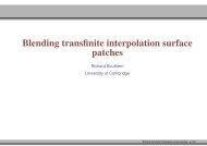
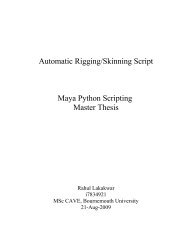
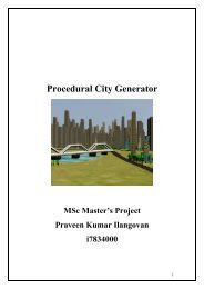
1 IntroductionThe idea to create an automatic <strong>rigging</strong> tool <strong>for</strong> <strong>centipedes</strong> <strong>and</strong> <strong>millipedes</strong> wasborn shortly after the first presentation of the master projects. During a talk atthe campus with Kier Eyles, who studies Computer Animation at the NCCA,the question was raised how a rig would look like <strong>for</strong> a centipede or millipede.This question resulted in the present master project.Figure 1: Examples <strong>for</strong> different <strong>centipedes</strong> <strong>and</strong> <strong>millipedes</strong>. Pictures taken atthe Natural History Museum in London or the Colgne ZooNormally, a <strong>rigging</strong> project starts with the collection of reference material ofanatomy <strong>and</strong> similar example rigs that others have already created be<strong>for</strong>e. Theproblem in this case was that the reference material was very limited. Mostof the books about arthropods 1 focus either on bugs, spiders or crabs. Centipedes<strong>and</strong> <strong>millipedes</strong> are either not covered at all or only within some pages.Furthermore, most of the photo material found on the internet showed only afew features of the body. It has been even harder to find high quality videosto observe the motion of <strong>centipedes</strong> <strong>and</strong> <strong>millipedes</strong>. Finally, observation of realcreatures was done in the Natural History Museum in London <strong>and</strong> the CologneZoo. This research improved significantly the underst<strong>and</strong>ing of anatomy <strong>and</strong>locomotion of <strong>centipedes</strong> <strong>and</strong> <strong>millipedes</strong> <strong>and</strong> helped to analyse photos or videos1 The phylum Arthropods includes all invertebrate animals with an exoskeleton. These areamong others, insects, crabs, spiders or <strong>centipedes</strong> <strong>and</strong> <strong>millipedes</strong> [Cla73].5
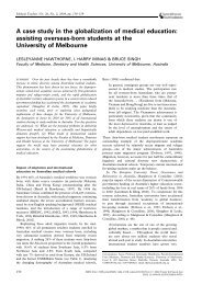
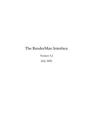
case of movement. In opposite to mammals, bodies of arthropods are only de<strong>for</strong>medat joints where the cuticle remains soft <strong>and</strong> flexible. Other parts of thecuticle are hardened <strong>and</strong> inflexible [MO01, p.175]. Muscles of arthropods arehidden under the exoskeleton <strong>and</strong> are there<strong>for</strong>e invisible. In general, a joint ofarthropods can be imagined as the intersection point of two non de<strong>for</strong>mabletubes, one stitched into another. The surface between the tubes is soft <strong>and</strong>there<strong>for</strong>e de<strong>for</strong>mable. Depending on the size of the inserted tube, the joint maybe very flexible or completely rigged, also an offset of the inserted tube fromthe centre may change the degree of freedom in certain directions as describedin [Cla73, p.36-39] or figure3.Figure 2: Cross section of an exoskeleton [WWE80, p.108]Millipedes <strong>and</strong> <strong>centipedes</strong> consist both of numerous segments (more than15) with one or two pairs of legs. All segments with legs tend to be similar<strong>for</strong> one creature, but can differ in length <strong>and</strong> <strong>for</strong>m between the several species.The head of the <strong>millipedes</strong> <strong>and</strong> <strong>centipedes</strong> consists of two antennas, primitiveeyes, m<strong>and</strong>ible <strong>and</strong> at least one pair of maxillae 3 . As <strong>centipedes</strong> are predatorsin opposite to most <strong>millipedes</strong>, they have a second pair of maxillae as poisonclaws. Another difference between <strong>centipedes</strong> <strong>and</strong> <strong>millipedes</strong> is visible at the lastbody segment, where <strong>centipedes</strong> have long legs facing to the back <strong>and</strong> acting likeantennas. As the name already implies, <strong>centipedes</strong> have less legs than <strong>millipedes</strong>in total <strong>and</strong> per segment. Centipedes have only one pair of legs per segment<strong>and</strong> between 15-177 segments [WWE80, p.159-161]. The number of segments <strong>for</strong><strong>millipedes</strong> is similar, although in average higher than of <strong>centipedes</strong>, but becausethere are, excluding the first four segments, two pairs of legs per segment, thetotal number of legs is higher. The creature with the most legs (more than 600)is Illacme plenipes.Further differences between <strong>centipedes</strong> <strong>and</strong> <strong>millipedes</strong> derive from their behaviourin nature. As <strong>centipedes</strong> are predators eating small insects <strong>and</strong> spiders,they are fast, flexible <strong>and</strong> flat. Their body is soft, except strong cuticles at theback <strong>and</strong> the lower side. Their legs are placed at the sides of the body. Inopposite, <strong>millipedes</strong> digest plants or decaying material <strong>and</strong> live in soil. Their3 see also figure47
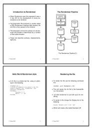
Figure 3: Main joint types of arthropods with different level of flexibility [Cla73,p.37]Figure 4: Head anatomy of a centipede <strong>and</strong> a millipede [Uni10],[WWE80, p61]8
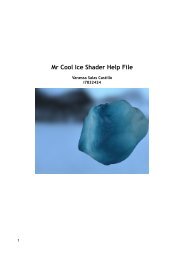
Figure 5: Examples <strong>for</strong> different <strong>centipedes</strong> <strong>and</strong> <strong>millipedes</strong> - Top left: VietnameseCentipede - Top center: House centipede - Top Right: Pill millipede- Bottom: Giant millipede [MO01, p.218-219],[Jan05]bodies are round, hard <strong>and</strong> the legs are placed at the lower side. Millipedesoften coil up their body into spirals <strong>and</strong> some even into pills. In order to havesuch a flexible back but being at the same time well protected, the cuticles ofeach segment overlap each other when the back is straightened as it can be seenin figure 2.The legs of myriapoda are constructed in a simple way in comparison to thelegs of other insects. The joint between the coxa 4 <strong>and</strong> the body allows the back<strong>and</strong><strong>for</strong>ward motion of the leg, the joints around the trochanter act like a kneejoint allowing the leg to move up <strong>and</strong> down, but with a higher degree of freedom<strong>for</strong> motion in the up direction. The joints from the femur to the pretarsus aresimilar to the joints around the trochanter, but have a higher degree of freedomin the down direction [Cla73, p.40].3 Locomotion of Millipedes <strong>and</strong> CentipedesThe motion of the <strong>centipedes</strong> <strong>and</strong> <strong>millipedes</strong> is very little discussed in literaturein general <strong>and</strong> mostly with a main focus on legs. There<strong>for</strong>e, most of thedescription of the motion in this thesis is based on personal observation of real<strong>millipedes</strong> in the zoo or from video examples [Nat07], [mem07]. For a better4 compare with figure 69
Figure 7: Different possible spine de<strong>for</strong>mations of a millipede/centipede. Left:Lifting front body - Center: Lifting of the body center - Right: Lifting of theend segmentsSpineThe movements of the spine in combination with the legs are the key <strong>for</strong> correctanimation of <strong>centipedes</strong> <strong>and</strong> <strong>millipedes</strong>. Their spine joints are flexible in eachdirection <strong>and</strong> each segment can be controlled separately, but as each spine segmentis very short compared to the total size of the creature, the spine appearsmore like a chain. During the observation of <strong>millipedes</strong>, the following typicalbehaviour has been discovered. First of all, there is no significant up <strong>and</strong> downmovement of the spine if the millipede is walking. In opposite to mammalsthat tend to move their spine in vertical direction, <strong>millipedes</strong> have more legs,which provide them with more stability while walking. As they move <strong>for</strong>- orbackward, the majority of the legs stays at the ground, <strong>and</strong> there<strong>for</strong>e, any upor down movement of the spine would cause that more legs are unnecessarilymoved <strong>and</strong> energy would be wasted. But there is another interesting fact when<strong>millipedes</strong> or <strong>centipedes</strong> are moving <strong>for</strong>ward. Millipedes normally dig in soilwhere they create small tunnels of the diameter of their body, <strong>and</strong> there<strong>for</strong>e,each segment of the spine follows the motion path of the head. This has theeffect that <strong>millipedes</strong> always seem to walk along an invisible line. The slowwalk of <strong>centipedes</strong> is similar. Their body segments also follow the same motion11
Figure 8: Motion path comparison between a walking millipede <strong>and</strong> a runningcentipedepath, but when <strong>centipedes</strong> are running or swimming, they tend to move likesnakes. In such a case, their spine looks more like a sinus function <strong>and</strong> less likea curve following a path. Besides walking, <strong>millipedes</strong> explore their environmentmoving the spine to look around. They lift their front body <strong>and</strong> move it sideby side. A similar motion happens if a millipede wants to change its direction.In this case, it lifts the front body only as much as needed to lift the front legsfrom the ground <strong>and</strong> moves the spine sidewards. Finally, it continues to walkinto the new direction. Besides its front body it can also lift central segmentsof the spine or the back. This behaviour can be seen in the video of NationalGeographic [Nat07] or in figure 8, where the centipede lifts the central segmentsof its body to carry babies or where it lifts the back during the fight against themouse.LegsThe movement of the legs is actually the most fascinating part of myriapoda,because the legs look like a wave while walking 5 . This wave is the result ofeach pair of legs being in phase, but slightly out of phase to the previous pair.To avoid stumbling about its legs, each pair is never moved further than theprevious one. The motion of each leg can be subdivided into two parts. Duringthe transfer stage the leg is lifted <strong>and</strong> moved <strong>for</strong>ward. In opposite to that,the leg stays attached to the ground <strong>and</strong> pushes the body <strong>for</strong>ward during thepropulsive stage. There are different theories that try to simulate the motion ofeach leg. The first was mentioned by Sinclair, who reports that the legs movein a set of five [Sin85]. Another model is mentioned in [Sat04]. It is based5 see there<strong>for</strong>e the enclosed video12
on the assumption that the motion of each leg can be described with cycloidfunctions. But the authors of the same paper criticises that this assumption iswrong <strong>and</strong> suggest their model based on a circle of reference. Similar to theprevious model, Sathirapongsasuti describes the movement of a millipede withthe help of a circle, but takes only one part of the circle to simulate the motionof the leg. The problem with all approaches is that the described solution isonly valid <strong>for</strong> a constant <strong>for</strong>ward speed <strong>and</strong> only if the millipede is movingstraight <strong>for</strong>ward, which makes it suitable <strong>for</strong> computer graphics only to a verylimited point. Although the “circle of reference” seems to be more suitable <strong>for</strong>the simulation of a leg, it is at the same time more complex <strong>and</strong> relies <strong>for</strong> achanging of speed on heavier computation. In opposite to that, the methodof cycloid functions simulates as well an arc as steps <strong>for</strong> the millipede, but isfaster to compute <strong>and</strong> experiment with it is easier. There<strong>for</strong>e, it seems to be themethod of choice to implement. It is also to doubt whether an inexperiencedviewer would notice the difference between the two approaches.4 Millipedes <strong>and</strong> <strong>centipedes</strong> incomputer graphicsInsects are widely present as virtual characters in film <strong>and</strong> television, in manylike “A Bug’s Life”, “Ants”, “Joe’s Apartment” they even became main characters.This fact motivated the research about <strong>centipedes</strong> <strong>and</strong> <strong>millipedes</strong> shownin recent movies, hoping to find existing <strong>rigging</strong> examples <strong>for</strong> these creatures.Un<strong>for</strong>tunately, only four film examples have been found, but only one can beconsidered as realistic. The first example with <strong>millipedes</strong> is “A Bug’s Life”,where cartoon <strong>millipedes</strong> are shown towards the end of the film. As these charactersare only shown <strong>for</strong> a couple of seconds, they are designed in a very simplemanner <strong>and</strong> no in<strong>for</strong>mation has been found about their design or set-up. Besidesthe two <strong>millipedes</strong>, there are two pill bugs in the film <strong>and</strong> the bonus-DVDcontains some sketches of their bodies, which may serve as a good modellingreference <strong>for</strong> spine segments <strong>and</strong> joints <strong>and</strong> gave at the beginning of this projectsome helpful in<strong>for</strong>mation about the general design of insects <strong>and</strong> how they canbe stylised <strong>for</strong> an animation film.Another example <strong>for</strong> <strong>centipedes</strong> has been found in “King Kong” by PeterJackson, where Weta Digital created a giant centipede that attacks Ann Darrow,who is played by Naomi Watts. This example is the best example <strong>for</strong>a realistically computer animated centipede. The body <strong>and</strong> the motion arebased on real <strong>centipedes</strong> <strong>and</strong> only the shape of the mouth seems to be designedby an artist. Other examples of Myriapoda in film are the Arthropleura in13
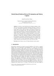
Figure 9: Sketches of a pill bug from Pixar’s “A Bug’s Life”[Les99]Figure 10: Top: Screenshot from King Kong with a centipede [Jac05], Bottom:Screenshot of a millipede from “A Bug’s Life”[Les99]14
“Prehistoric Park – The Bug House” [BBC06] or an unreal giant centipede in“Primeval-Episode 1.2” [Hai07]. But the last examples are less suitable as reference,because the creatures are only shown <strong>for</strong> seconds <strong>and</strong> interrupted by manycuts.Un<strong>for</strong>tunately, no description about the <strong>rigging</strong> of any of these creatureshas been found, but instead two other <strong>millipedes</strong>’ rigs. The millipede rig ofTapani [Tap08a] is completely created as an ICE system with dynamics in Softimage|XSI,but as he indicates in an internet <strong>for</strong>um, the rig is not suitable <strong>for</strong>production <strong>and</strong> might be “hacky” [Tap08b]. The main idea of this rig was toexperiment with ICE, <strong>and</strong> there<strong>for</strong>e, it is underst<strong>and</strong>able that it only provideslittle control <strong>for</strong> the animator. In his solutions the creature walks along a path<strong>and</strong> legs are moved automatically with the help of dynamics. Another solutionto rig a millipede is given by Nelson [Nel08]. Although the description is veryshort <strong>and</strong> the videos are not displayed correctly in the browser, it seems thathe implemented a basic rig with the help of expressions that time-delay themovement of the first segment.5 Implementation5.1 Software <strong>and</strong> Scripting languagesSome attention should be paid to the software system <strong>and</strong> the scripting languagesused <strong>for</strong> this project, be<strong>for</strong>e a detailed description of the <strong>rigging</strong> systemis given. For this project, Autodesk Maya has been chosen because of personalpreference <strong>and</strong> its popularity within the 3D-industry. But many other softwarepackages like Softimage|XSI, Houdini or Blender are suitable as well <strong>for</strong> theimplementation of this <strong>rigging</strong> system. In fact, any software that fulfils thefollowing requirements can be considered as suitable:• is extensible by a scripting or programming language to create rigs procedurally• supports custom user interfaces• provides expressions or other similar tools to create custom dependenciesor animation• provides inverse kinematics comparable to the “Rotation Plane Solver”<strong>and</strong> the “Spline Solver” in Maya• offers the possibility to create a path animation <strong>for</strong> a curve that will de<strong>for</strong>mthe curve according to the path15
has been used. The names <strong>for</strong> all created nodes start with their object type (e.g.Controller, Group), followed by the body part (e.g. Head, Leg), which is sometimessupplemented by the segment number. Finally, the name of the creature itself is added.5.4 Positioning the jointsAfter the definition of the names, the user has to define the position of the joints. Asmany other creatures, <strong>millipedes</strong> <strong>and</strong> <strong>centipedes</strong> are symmetrical, moreover, they alsohave a repeatable pattern at their spine <strong>and</strong> legs. Obviously, it might take a whileuntil all the joints of a 100-leg centipede are positioned correctly. To simplify thisprocedure, the locators that will later be replaced by joints, are created step by step.In the first step only the head, the root <strong>and</strong> the end segments are created. The usershould now position the locators according to his individual creature. The position ofthe head <strong>and</strong> the end segment is then used to distribute equally all the spine segments.Of course it cannot be assumed that the computed position of all spine joints is right,<strong>and</strong> there<strong>for</strong>e, the user still has the possibility to adapt the position of the locators tohis individual character. A similar algorithm is also applied to the legs of the creature.According to the side specified by the user, the first <strong>and</strong> the last leg is created. Afterpositioning the first <strong>and</strong> the last leg, all the other legs are created with an equaldistance between each other. The derivation of the position <strong>for</strong> the in-between legs<strong>and</strong> spine segments guarantees at least that the position of the joints is close to thereal position of the character. Although this solution is not ideal, it is definitely betterthan guessing the position of hundreds of legs.Furthermore, the user has to define the position of the joints <strong>for</strong> the antenna <strong>and</strong>the maxilla(e). If this is done, one side of the creature is finished <strong>and</strong> all the locatorscan be mirrored to the other side in order to take advantage of the creature’s symmetry.Of course, the names of the mirrored locators have to be modified accordingly. Evenat this late stage the user still has the chance to modify the position of every locator,<strong>and</strong> as there is no hierarchical relationship between the locators, moving one locatorin space does not affect the position of any other locator. This was the main reasonto define all joint positions first with locators instead of using joints that are mostlycreated in hierarchical structures.Pseudo-code <strong>for</strong> locator creation:create root, head <strong>and</strong> end locator at default position-----------wait-----------user defined position of the head <strong>and</strong> end locatoras well as the number of spine segmentscompute the distance between head <strong>and</strong> end locatorcompute equal distance between every spine segment<strong>for</strong> all spine segments18
create spine segment <strong>and</strong> place at computed position-----------wait-----------user input <strong>for</strong> the number of leg segments <strong>and</strong> the sidecreate first <strong>and</strong> last leg at first <strong>and</strong> last spinewaituser defined position of all joints <strong>for</strong> the first <strong>and</strong>the last leg as well as the number of legs<strong>for</strong> each segmentget position of the segment of the first <strong>and</strong> last legcompute distance<strong>for</strong> all legsplace leg segments at computed position-----------wait-----------user defined number of antenna segmentscreate default antenna-----------wait-----------user defined number of maxilla segmentscreate default maxilla-----------wait-----------user positioned all locatorscreate all leg, antenna <strong>and</strong> maxilla locators on the other side5.5 Creating the rigUntil now the <strong>rigging</strong> system relied a lot on user input. For this last step, the useronly has to select the features he wants <strong>for</strong> his rig <strong>and</strong> then the rig will be created.Nevertheless, this part is the core of the <strong>rigging</strong> system <strong>and</strong> became more <strong>and</strong> morecomplex during the progress of this project. After a while it became clear, that inorder to achieve all the requirements, more than one <strong>rigging</strong> system would be needed.The following chapters describe how several independent rigs are designed, how theyinteract with each other <strong>and</strong> how they help the animator.The Binding RigThe binding rig is a basic chain of joints. It starts with the first spine joint whichis the parent to the head, <strong>and</strong> the next spine joint which becomes the parent19
Figure 11: Simplified Maya tree to indicate the internal joint hierarchyof the following spine joint. This results in a long chain of bones <strong>for</strong> the spine.Furthermore, every spine joint is as well parent <strong>for</strong> the according pair of legs.The maxilla <strong>and</strong> the antennas are parented to the head joint. The completehierarchy is illustrated by a simple example in figure 11 As the name of the rigindicates, this rig is bound to the mesh of the character <strong>and</strong> all the animationis derived from other independent rigs. The separation between a binding rig<strong>and</strong> a rig to animate becomes very h<strong>and</strong>y if more features are added to the rigduring the production. New <strong>rigging</strong> features added during production manytimes require as well the replacement of the rig as the weights <strong>for</strong> skinning. Inopposite to that, a binding rig can save time as the feature would be added toone of the independent rigs <strong>and</strong> only the resulting motion would be passed overto the binding rig [Rit06]. Furthermore, binding rigs can reduce complexity dueto the possibility to blend between the motions of several independent rigs. Thishas been the main reason to implement the binding rig <strong>and</strong> give the animatorthe possibility to blend between the master <strong>and</strong> the automatic walking rig thatwill be discussed more in depth in the following sections.20
The Master RigOriginally, the master rig should be a simple rig that provides the animatorwith several functions to animate each joint individually. But after a while itbecame clear, that the dem<strong>and</strong> to animate one leg separately many times willnot be given. Instead, it is more likely that the animator will animate severallegs at the same time, as the motion of one leg mostly affects as well the motionof the other legs of a centipede or a millipede. There<strong>for</strong>e, it seemed to be moreefficient to create a controller that enables to animate some master legs <strong>and</strong> theninterpolate all the other legs automatically. To achieve that, another rig systemhas been created on top to the normal rig. The difference between the first <strong>and</strong>the second rig that will be called the master rig is only the number of legs <strong>and</strong>spine segments. The user has the possibility to define the number of masterlegs <strong>and</strong> spine segments <strong>and</strong> to control thereby the level of abstraction <strong>for</strong> themaster rig. In the current implementation the position of the legs is linearlyinterpolated by expressions between the positions of the two closest master legs.As expressions are evaluated every time when the master rig has been moved,it is important to precompute as much as possible in order to save computationtime. The number of legs is always constant <strong>for</strong> the rig, <strong>and</strong> that is why theweighting values <strong>for</strong> the legs are constant <strong>and</strong> can be precomputed during therig creation.In order to have more control over the motion of the master rig, each masterleg has a separate bone chain <strong>for</strong> FK <strong>and</strong> IK animation 7 , which is linearlyblended with an IK-FK switch. Luckily, the default motion created by an FKcontroller is very close to the natural motion of a centipede or a millipede leg.The joint at the coxa 8is moving back- <strong>and</strong> <strong>for</strong>ward, the joints around thetrochanter are bended during the up motion while the joints around the femurare bended during the down motion.To add as well an IK-FK switch to the spine, a different approach has beenchosen. First of all, an IK spline solver has been added to the spine chain of themaster <strong>and</strong> the normal rig. Both chains share the same spline <strong>and</strong> there<strong>for</strong>e thesame de<strong>for</strong>mation. To control the shape of the spline, all knots are individuallyclustered 9 <strong>and</strong> IK controllers are created at the position of the cluster. Additionally,another joint chain is created that starts from the closest spine joint to theroot position 10 <strong>and</strong> has a joint at all knot positions of the spline. If the joints areparented to the spline knots, the bone chain results as an FK controller <strong>for</strong> thespine. Again, an IK-FK switch controls whether the knot position of the spline7 FK <strong>and</strong> IK are common abbreviations <strong>for</strong> <strong>for</strong>ward kinematics <strong>and</strong> inverse kinematics8 see figure 69 Clusters are de<strong>for</strong>mers which enables to group parts of an object like knots, vertices, etc.<strong>and</strong> to modify the individually [Aut09]10 see figure 1221
Figure 12: An Example <strong>for</strong> the construction of the spine; Left: Spine of thenormal rig - Center: Spine of the master rig - Right: NURBS spline withclusters to control the position of the spline knotsis inherited from the IK controllers or from the FK joint chain. In opposite tothe legs <strong>and</strong> the spine segments, the motion of any antenna or maxilla does notaffect the motion of any other body part. There<strong>for</strong>e, no simplification couldbe achieved <strong>for</strong> these parts of the body. To avoid confusion of the animator, ithas been decided that all controllers should be moved to the master rig <strong>and</strong> thenormal rig should only inherit the motion from the master rig. There<strong>for</strong>e, allthe joint chains <strong>for</strong> the antennas <strong>and</strong> the maxillae are copied to the master rig.Similar to the legs of the master rig, maxillae have as well a separate joint chain<strong>for</strong> the IK <strong>and</strong> FK animation which is blended by an IK-FK switch. The set-upof the antennas is comparable to the set-up of the spine. Each antenna has anIK spline solver with controllers that are parented to the knots of the spline.5.6 <strong>Automatic</strong> Walking RigFirst attempt using custom Catmul-Rom splinesThe automatic walking rig has been by far the most challenging part of the<strong>rigging</strong> system <strong>and</strong> it took two different approaches to create this rig. Butbe<strong>for</strong>e the animation of the legs could be driven by expressions, a solutionneeded to be found that transfers the applied path animation to the spine of a22
Figure 13: Examples <strong>for</strong> the joint structure; Left: Master rig - Center: <strong>Automatic</strong>walking rig - Right: Binding rigFigure 14: Hierarchy of the <strong>rigging</strong> system in combination with bounded geometry23
Figure 15: Illustration of the assumption that the motion path can be reconstructedfrom the spine segments - t(i) indicates the current frame <strong>and</strong>slshapet(i+1) the next framemillipede or centipede. Un<strong>for</strong>tunately, first attempts to create a bone chain thatde<strong>for</strong>ms according to the path animation with built-in functions in Maya havefailed, <strong>and</strong> there<strong>for</strong>e, the following concept has been developed. The basic ideaof this concept is the assumption that the distance which each spine segment iscovering from frame to frame, is very short in comparison to the total length ofthe creature. Furthermore, it is known that every segment of the creature alwaysfollows the motion path of its previous segment. Consequentially it means thatif an interpolation spline is created through the joint of the spine <strong>and</strong> then eachjoint is moved further a certain distance along the spline, the resulting motionshould be very close to the motion along a path. Of course it might be that thespine bones change their length during the animation, but this change of thelength has been considered in theory as very small 11 . Furthermore, it has beenthe only chance to realise such a motion, because all attempts to create a similarmotion with the basic tools of Maya failed up to this point. In the case that thisapproach could have been confirmed in practices, it also would have simplifiedpath animation. In opposite to current approaches, the animator could onlyuse key-frame animation instead of switching between path animation <strong>and</strong> keyframeanimation.As Maya only provides NURBS splines that belong to approximation splines,a custom class that provides the functionality of the Catmull-Rom splines hasbeen developed in Python. Catmul-Rom splines have been chosen, becauseit is possible to construct it only from the given interpolation points <strong>and</strong> no11 see figure 1524
additional in<strong>for</strong>mation is needed, which has been considered as a big advantageto many other interpolation splines. The matrix representation of the Catmul-Rom spline is given in equation 1 [Par08]P (u) = U T MBU T = [ u 3 u 2 u ]⎡M =⎢⎣2 −2 1 1−3 3 −2 −10 0 1 01 0 0 0⎤⎥⎦(1)⎡B =⎢⎣P iP i+1P i‘P i+1‘⎤⎥⎦In order to be able to compute P(u) as well between the first <strong>and</strong> the secondinterior point, the initial tangent has been <strong>for</strong>med by equationP − 1 = P 1 − (P 2 − P 1 ) (2)<strong>and</strong> accordingly the end tangentP i + 2 = P i − (P i − 1 + P i ) (3)As the arc length often cannot be computed analytically <strong>for</strong> a curve, a <strong>for</strong>warddifferencing algorithm has been implemented as suggested in [Parent]. Inorder to compute the arc length from P(0) to P(0.23), this approach would firstcompute the position of several in-between points <strong>and</strong> then approximate thearc length by adding the distance between the points. Firstly, the distance iscomputed between P (0) <strong>and</strong> P (0.2)d(0.2) = P (0.05) − P (0.0)+P (0.1) − P (0.05)+P (0.15) − P (0.1)+P (0.2) − P (0.15)(4)<strong>and</strong> then linearly interpolated with the distance between P (0) <strong>and</strong> P (0.25)After implementing the algorithms <strong>for</strong> Catmul-Rom splines <strong>and</strong> the arclength, first test have been done in Maya to see whether the theoretical as-25
sumptions could be confirmed. A chain of joints that represent the spine of amillipede has been created. The first spine joint has been animated by key-frameanimation, while all the other joints should be controlled by an expression. Thisexpression takes at first the current position of all joints <strong>and</strong> the previous positionof the first joint. Then it creates a Catmull-Rom spline from all points <strong>and</strong>computes the distance that the first joint has moved between the last <strong>and</strong> thecurrent frame. In the next step, every expression driven point is moved by thesame distance along the Catmul-Rom spline.Un<strong>for</strong>tunately, the theoretical assumptions <strong>for</strong> this approach could not beconfirmed. The first test showed that the bone length is changing significantlyafter some frames, furthermore the frame rate dropped to less than real-time.As this approach seemed to be at that time the only way to implement an automaticwalking rig, a lot of ef<strong>for</strong>t has been put to guarantee that all the splinefunctions are bug free. Although extensive testing has uncovered some computationerrors, the significant length change of the bone could not be solved atthis point. This drawback motivated again the research on the default functionalitiesof Maya <strong>for</strong> path animation <strong>and</strong> whether there is a solution to de<strong>for</strong>m abone chain according to a motion path. Luckily, the following solution has beendiscovered.Second attempt with default path animation in MayaThe second attempt to create an automatically walking millipede is mainlybased on default Maya functionalities that are extended at certain points byexpressions. At first, an IK spline solver with a new curve is created <strong>for</strong> thespine of the millipede, then the curve is attached to a motion path. Until nowthe creature would only follow the path but not de<strong>for</strong>m its spine. In order toachieve that, the “flow” function of Maya is used. This will create a latticearound the curve that will be de<strong>for</strong>med according to the shape of the motionpath. Of course the number of divisions <strong>for</strong> the lattice should be at least thesame as the number of spline knots that control the spine chain. With the appliedflow function the de<strong>for</strong>mation of the motion path is now transferred to thecreature’s spine.In addition to the spine de<strong>for</strong>mation, a procedural animation needs to beadded to the legs. Although Sathirapongsasuti derives several equations <strong>for</strong> theleg motion of <strong>millipedes</strong>, they are un<strong>for</strong>tunately based on assumptions that arenot fulfilled in the present <strong>rigging</strong> system. In his work the millipede is movingwith a constant speed along a path, but as the animator controls the speed of thecreature, this assumption is not given. Luckily, the starting <strong>and</strong> ending pointof the animation is known <strong>and</strong> the distance along the path from the currentposition to the starting position can be computed <strong>for</strong> any frame. In terms of26
Figure 16: Simplified walking cycle of a legMaya this means to create an “arcLengthDimension” node <strong>for</strong> the spline thatdefines the motion path, <strong>and</strong> then connect the current position of the creaturewith the position of the arcLenghtDemension node. As the arcLenghtDemensionnode returns the length of the spline between the starting point <strong>and</strong> the currentpoint, it is now possible to access the distance along the path.In order to calculate the motion of the legs <strong>and</strong> to save computation time, asimplified concept of Sathirapongsasuti has been used. It is mainly base on theobservations of Sathirapongsasuti but ignores that each leg moves along a circleof reference. It is assumed that the leg moves along a circle <strong>and</strong> can be dividedin a propulsive <strong>and</strong> a transfer stage. During the transfer stage the leg is lifted<strong>and</strong> moved <strong>for</strong>wards. In opposite to that, the leg is moved backwards duringthe propulsive stage while the body is pushed <strong>for</strong>wards. There<strong>for</strong>e, it can beassumed that the local trans<strong>for</strong>mation in x direction is equal during the propulsive<strong>and</strong> the transfer stage in terms of the length, but contrariwise in terms ofthe direction. The trans<strong>for</strong>mation in the y direction is during the propulsivestage 0 because the tip of the leg stays attached to the ground, <strong>and</strong> during thetransfer stage it follows the circular motion.With the reduction to a circular motion x <strong>and</strong> y can be computed as following:x = −r · cos s − φ · dry = −r · sin s − φ · drS is representing the moved distance from the starting point, d the distanceof the leg from the first leg, φ the phase, r the radius of the circle <strong>and</strong> the minus isan offset of 180 ◦ that guarantees that the first pair of legs starts with the transferstage. In order to give the animator more control over the walk, he can modifyphi to change the phase between the legs. Furthermore, he has control over r(5)27
that changes the step size, which should be modified when legs start to intersecteach other. Additionally, a constant has been added to the computation of y inorder to be able to adjust the step height. In the implementation of the <strong>rigging</strong>system in Maya these <strong>for</strong>mulas have been used to manipulate the position ofthe IK h<strong>and</strong>les of the legs.6 Program structureThis project was not only challenging because of the complexity of the topic,it became even more challenging because only little experience existed be<strong>for</strong>ewith the scripting languages Python or MEL <strong>and</strong> no experience about scripting<strong>for</strong> Maya. The consequence was that especially at the beginning most of thecode has been developed just <strong>for</strong> special use cases. But in the course of timeit became clear that parts of the code could be changed into general functions<strong>and</strong> called at different parts of the system. There<strong>for</strong>e, the internal coding structureof the <strong>rigging</strong> tool has been restructured several times during the project<strong>and</strong> still needs some restructuring to increase productivity <strong>for</strong> further development.Although Python is an object oriented language, this feature has notbeen used <strong>for</strong> this project because only very little data is saved <strong>and</strong> most of thedata is used at several parts of the program. For this specific project, it seemedthat the advantage of a better structure created by an object oriented approachcould also be achieved if all the functions were distributed to different Pythonmodules. Using these modules as containers <strong>for</strong> specific functions is comparableto the use of objects that save no data at all. Finally, all modules have beenbundled in one Python package that currently consists of the following modules:__init__The default module <strong>for</strong> each package that provides the in<strong>for</strong>mation of the othermodules.MillipedeRigThe MillipedeRig contains all rig related functions. This can be general functionsthat only create a simple joint chain or very specific functions that createthe master rig.MillipedeLocThe MillipedeLoc module contains all functions that create any locators thatwill later be replaced by joints.28
UserInterfaceThis module contains all the functions needed to create the user interface. Italso saves the in<strong>for</strong>mation how Maya has to call functions of the other moduleof the <strong>rigging</strong> system in order to communicate between the <strong>rigging</strong> system <strong>and</strong>the interface.RigDataThis module saves all the naming conventions <strong>and</strong> provides a rich set of functionsto get proper names of several parts of the rig.UtilityThis module extends some functionalities of Maya by combining several functionsof Maya. For example, it provides functions that copy the position of oneobject to another.CatmullRomSplineThe CatmullRomSpline module supports the creation of Catmul-Rom splines<strong>and</strong> provides functions to compute the arc length of the curve or to detect pointsalong the spline that are positioned at a certain distance from another point ofthe spline. But as described earlier, this module could not been used <strong>for</strong> this<strong>rigging</strong> system.Wire ControllerThis module is a custom Python version of a more elaborated Mel script from[Sol03].euclidThis module has been taken from [Hol10] <strong>and</strong> provides vector <strong>and</strong> matricesmathematics in Python.7 ConclusionThis master project has been a big challenge because it combines many tothe author up to this point unknown areas of expertise like the anatomy of<strong>centipedes</strong> <strong>and</strong> <strong>millipedes</strong>, Catmull-Rom splines, scripting <strong>for</strong> Maya <strong>and</strong> thescripting language Python. During this project, detailed knowledge has beenobtained of the anatomy <strong>and</strong> locomotion of <strong>centipedes</strong> <strong>and</strong> <strong>millipedes</strong>, which isdocumented in this thesis. Although strong ef<strong>for</strong>t has been made to find detaileddescription of the locomotion of <strong>millipedes</strong>, only few sources have been found<strong>and</strong> it might be that the description of the interaction between the legs <strong>and</strong>29
the spine has not been documented be<strong>for</strong>e. Furthermore, individual solutionshave been found <strong>for</strong> crucial <strong>rigging</strong> problems in the context of this project. Forexample, an automatic walking rig has been developed, whose motion is veryclose to the natural motion of <strong>millipedes</strong> <strong>and</strong> <strong>centipedes</strong>, or a special rig hasbeen designed to simplify the animation of numerous legs. Un<strong>for</strong>tunately, timehas been lost during the first unsuccessful implementation of the automaticwalking rig. But this is comprehensible as this project could not rely on anyother comparable work. At the same time, it has been a nice learning experienceabout the implementation details of a path animation system <strong>and</strong> interpolationsplines. Although the current implementation of the <strong>rigging</strong> system does notsupport all anatomical characteristics of <strong>millipedes</strong> <strong>and</strong> <strong>centipedes</strong>, it is so farthe most flexible <strong>rigging</strong> system known to the author, <strong>and</strong> the remaining options<strong>for</strong> the rig should be implemented within a short amount of time.Like in the case of many other programming projects there is always somethingthat could be improved. Possible improvements of the <strong>rigging</strong> systemwould be a user interface that is created with the rig <strong>and</strong> provides better controlof all switches that either blend between different rigs or between IK <strong>and</strong>FK. Furthermore, feedback should be collected from animators, <strong>and</strong> if thereare any mayor concerns according to the usability or the functionality of therig, their suggestions should be implemented as well. Additionally, this <strong>rigging</strong>system could be extended with only little ef<strong>for</strong>t to a general <strong>rigging</strong> system <strong>for</strong>worms, snakes or many arthropods, like spiders, insects or shrimps. As the toolis designed to create several legs <strong>and</strong> spine segments procedurally, only somenew rules according to the number of legs would be needed in order to createrigs <strong>for</strong> other creatures. For example, to create a worm rig, it would be sufficientto remove all extremities from the current system. In order to create a rig <strong>for</strong>shrimps or lobster, tongs would be added to the maxillae <strong>and</strong> the number of legswould be created independently from the number of spine segments. Overall,it seems that this project does not only provide an interesting solution to rig<strong>centipedes</strong> or <strong>millipedes</strong>, but as well many interesting approaches that could betransferred to rig other creatures.30
References[Autodesk, 2009] Autodesk (2009). Maya documentation.[BBC, 2006] BBC (2006). Prehistoric park - bugs house. http://www.youtube.com/watch?v=Wl7xZrtxb_I&feature=related.[Clarke, 1973] Clarke, K. U. (1973). The biology of the Arthropoda. Contemporarybiology. Edward Arnold, London.[Gould, 2003] Gould, D. A. D. (2003). Complete Maya programming: An extensiveguide to MEL <strong>and</strong> the C++ API. Morgan Kaufmann series in computergraphics <strong>and</strong> geometric modeling. Academic Press, San Diego, CA.[Haines, 2007] Haines, Tim, H. A. (2007). Primeval-episode1.2 (giant spiders<strong>and</strong> centipede). http://www.youtube.com/watch?v=MRomApaygfU.[Holkner, 2010] Holkner, A. (2010). pyeuclid. http://code.google.com/p/pyeuclid/.[Jackson, 2005] Jackson, P. (2005). King kong.[Janssen, 2005] Janssen, Ralf, P. N.-M. D. W. G. (2005). A review of thecorrelation of tergites, sternites, <strong>and</strong> leg pairs in diplopods. http://www.frontiersinzoology.com/content/3/1/2.[Lesseter, 1999] Lesseter, John, S. A. (1999). A bug’s life: collector’s edition.[Luma Pictures, 2010a] Luma Pictures (2010a). Pymel. http://code.google.com/p/pymel/.[Luma Pictures, 2010b] Luma Pictures (2010b). Pymel - documentation. http://pymel.googlecode.com/svn/docs/index.html.[memutic, 2007] memutic (2007). Scolopendra, the dangerous centipede of thail<strong>and</strong>.http://www.youtube.com/watch?v=C8HSkAr7v5g.[Moore <strong>and</strong> Overhill, 2001] Moore, J. <strong>and</strong> Overhill, R. (2001). An introductionto the invertebrates. Studies in biology. Cambridge University Press, Cambridge,New York.[National Geographic, 2007] National Geographic (2007). Centipede vs.grasshopper mouse. http://www.youtube.com/watch?v=AcYW31N96b4.[Nelson, 2008] Nelson, J. R. (2008). Millipede rig. http://www.jonathanrnelson.com/doodles.htm.31
[Parent, 2008] Parent, R. (2008). Computer animation: Algorithms <strong>and</strong> techniques.The Morgan Kaufmann series in computer graphics. Elsevier MorganKaufmann, Amsterdam, 2. ed. edition.[Ritchie, 2006] Ritchie, Kiaran, C. J.-B. K. (2006). The art of <strong>rigging</strong>: VolumeI ; a definitive guide to character technical direction with Alias Maya. Toolkit.[Sathirapongsasuti, 2004] Sathirapongsasuti, Jarupon, P. N.-W. P. (2004).Walking with a millipede: A mathematical explanation of millipede’swalk. http://files.thaiday.com/news/science/Walking_With_A_Millipede.pdf.[Sinclair, 1985] Sinclair, F. (1985). Myriapoda. In The Cambridge natural history,volume 5. Cambridge University Press, Cambridge.[Solsona, 2003] Solsona, Javier, L. L. (2003). rig101 wire controllers. http://student.vfs.com/~m07goosh/<strong>rigging</strong>101/freestuff.htm.[Tapani, 2008a] Tapani, A. (2008a). Milliped rig. http://anttontapani.com/index.php?option=com_content&view=article&id=7&Itemid=8.[Tapani, 2008b] Tapani, A. (2008b). Post on millipede rig inarea.http://area.autodesk.com/<strong>for</strong>um/autodesk-softimage/ice---interactive-creative-environment/<strong>rigging</strong>-a-millipede/.[University of Aberdeen, 2010] University of Aberdeen (2010).http://www.abdn.ac.uk/rhynie/centipede.htm.Centipedes.[Webb et al., 1980] Webb, J. E., Wallwork, J. A., <strong>and</strong> Elgood, J. H. (1980).Guide to invertebrate animals. Macmillan, London, 2. ed. edition.32