Installation & Instruction Manual - Reverse Osmosis, RO Water ...
Installation & Instruction Manual - Reverse Osmosis, RO Water ...
Installation & Instruction Manual - Reverse Osmosis, RO Water ...

You also want an ePaper? Increase the reach of your titles
YUMPU automatically turns print PDFs into web optimized ePapers that Google loves.
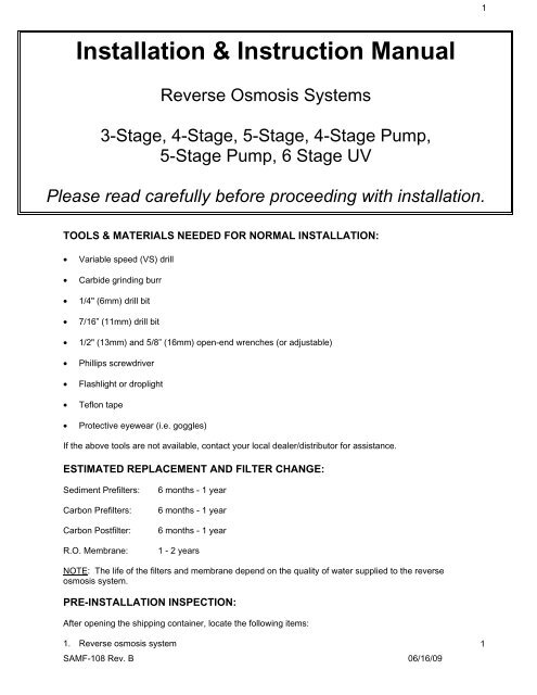
1<strong>Installation</strong> & <strong>Instruction</strong> <strong>Manual</strong><strong>Reverse</strong> <strong>Osmosis</strong> Systems3-Stage, 4-Stage, 5-Stage, 4-Stage Pump,5-Stage Pump, 6 Stage UVPlease read carefully before proceeding with installation.TOOLS & MATERIALS NEEDED FOR NORMAL INSTALLATION:• Variable speed (VS) drill• Carbide grinding burr• 1/4" (6mm) drill bit• 7/16” (11mm) drill bit• 1/2" (13mm) and 5/8” (16mm) open-end wrenches (or adjustable)• Phillips screwdriver• Flashlight or droplight• Teflon tape• Protective eyewear (i.e. goggles)If the above tools are not available, contact your local dealer/distributor for assistance.ESTIMATED REPLACEMENT AND FILTER CHANGE:Sediment Prefilters:Carbon Prefilters:Carbon Postfilter:R.O. Membrane:6 months - 1 year6 months - 1 year6 months - 1 year1 - 2 yearsNOTE: The life of the filters and membrane depend on the quality of water supplied to the reverseosmosis system.PRE-INSTALLATION INSPECTION:After opening the shipping container, locate the following items:1. <strong>Reverse</strong> osmosis systemSAMF-108 Rev. B 06/16/091
22. Storage tank3. Faucet with mounting hardware4. <strong>Installation</strong> packet containing: drain saddle, tank ball valve, two mounting screws, and otherinstallation pieces depending on system.OPERATION PARAMETERS:WARNING!! The following conditions for feed water supply must be met or warranty will be void.1. System must be connected to a municipal or well water source that is treated and tested on a regularbasis to insure water is microbiologically safe.2. Operating outside temperatures:Maximum 90 °FMinimum 40 °FCAUTION!! Do not allow system to freeze. The membrane always contains water and will bedestroyed if frozen.WARNING!! Do not plumb system to hot water. This will destroy the membrane and void thewarranty and manufacturer’s responsibility.3. Operating pressure:Maximum 80 PSIMinimum 40 PSIThis reverse osmosis system is designed to operate at a water pressure in the range of 40 to 80 PSI.At pressures lower than this, the quantity as well as quality will be reduced. At higher pressure,severe, damage to the system may result. A pressure regulator must be installed on the feedwater source, which reduces the water pressure coming into the system.WARNING!! Warranty voided and manufacturer assumes no responsibility for damage to system orproperty if pressure exceeds 80 PSI.4. Turbidity:
31Preparing For <strong>Installation</strong>Preparing for installation1. This system includes a standard sinktop faucet without an air-gap. Inlocalities where plumbing codes requireinstallation of an air-gap, contact yourlocal distributor to obtain a codeapproved drain line adapter.2. The reverse osmosis system may bemounted to the side of the sink cabinetor set on the floor of the sink cabinet. Itmust be positioned to allow access forservice and filter changes. Theassembly should be relatively near thefaucet to maximize flow rate. Seediagram A for a positioning example.3. The storage tank should be locatedwhere it can be removed if necessary.The storage tank may be placed ineither the vertical or horizontal positionwithout affecting the systemperformance. If there is insufficientspace under the sink for placement, thetank may be located in an adjacentcupboard up to 50 ft. away. Seediagram A for a positioning example4. The faucet should be positioned to allowa free flow pattern into the sink. It mustbe positioned to allow ready access tothe mounting hardware under the sink.See diagram A for a positioningexampleDiagram A2Faucet <strong>Installation</strong>CAUTION!! Extreme care must betaken in drilling the hole for the sink-topfaucet. The surface material of mostsinks is extremely hard and brittle andcan be easily chipped or cracked. If youare uncomfortable performing thefollowing procedure it is recommendedthat your local distributor be consultedfor techniques and other assistance.The system’s manufacturer accepts noresponsibility for sink top damageresulting from system installation.CAUTION!! Before grinding or drillingput on appropriate eye protection(i.e.…goggles) to protect yourself fromporcelain or metal chips.CAUTION!! Before grinding or drillingensure that the drill you are using isUL® Laboratories approved andproperly grounded to prevent electricalshock. DO NOT USE DRILL WHILEUSING OR STANDING IN WATER!!1. BEFORE DRILLING: Check under thesink in the area that you plan to installthe faucet and make sure that there is aflat surface to secure the mountinghardware. A flat space of approximately2 inches in diameter is needed.SAMF-108 Rev. B 06/16/093
4RECOMMENDATION: Before drilling orgrinding mask off the immediate areasurrounding the grinding/drilling locationpreferably with duct tape or if duct tapeis unavailable masking tape may beused. This procedure should helpprevent scratching of the sink surface.2. Remove everything from inside the sinkand surrounding area. Place papertowels in the sink to catch the shavingsfrom the grinding and drilling.CAUTION!! Porcelain or enamel mustbe completely removed in the drillingarea to prevent immediate dulling of drillbit.3. Remove everything from under the sink.4. Place newspaper or paper towelsdirectly under drilling location in order tocatch the drill shavings.5. Using the 1/4” (6mm) drill bit, drill acentering or pilot hole in the center ofthe desired faucet location. Note: thiscentering/pilot hole will make it easierfor the 7/16" (11mm) drill bit to cutthrough the sink. Operate the drillslowly and carefully—especially whenthe drill bit is about to penetrate themetal. Otherwise, damage to sink mayoccur. Use lubricating oil to keep thedrill bit cool while drilling.6. Discard paper towels and newspaperused in sink and below sink. Be verycareful not to drop any shavings in sinkor on the floor as they will oxidize andstain surfaces very quickly.hole again while rinsing off cleaner.Hole must be plugged in order to avoidwater dripping below into sink cabinet,which may cause damage.9. Remove faucet from package.For steps 11-14 refer to diagram B.10. Slip the small, thin rubber gasket overthe faucet shank. Next slip the chrometrim plate (escutcheon plate) over thefaucet shank. Finally, slip the large, thinrubber gasket over the faucet shank.11. Take the faucet spigot and insert it intothe faucet base in the hole next to thefaucet handle. Push the faucet spigot inuntil it stops.12. Place the faucet shank complete withonly hardware installed in step 11though the drilled hole.13. From under the sink slip the large, blackplastic, locating washer over the faucetshank. Next, slip the lock washer overthe faucet shank followed by the thinbrass nut.14. While holding the faucet assemblyabove the sink tighten the thin brass nutbelow the sink with an adjustablewrench. Tighten the brass nut until thefaucet assembly does not move.CAUTION!! Do not over tighten thebrass nut. Over tightening can causedamage to the sink or faucet assembly.7. Using a variable speed (VS) drill with acarbide grinding burr, gently grind awayenough porcelain or enamel to morethan accommodate the 7/16” (11mm)drill bit. Approximately the size of adime. Enough surface material must beremoved to expose the base metal.HELPFUL HINT: If you notice any rustspots from dropped shavings you shouldbe able to get rid of them by scrubbingthem with a cleaning chemical.8. Cover the drilled hole with your fingerBE VERY CAREFUL NOT TO CUTYOURSELF ON SHARP EDGES!Rinse sink then scrub with cleaner toprevent any rusting from shavings andto prepare for faucet installation. PlugSAMF-108 Rev. B 06/16/094
5Faucet DiagramUP FORCONSTANTFULL FLOW1. Turn off cold water supply to the sinkusing the supply valve located under thesink.2. Some shut off valves have an extra portfor an icemaker hookup. You will notneed the feed water adapter for this typeof installation.See diagram C.BLACK WASHERCH<strong>RO</strong>ME WASHERRUBBER GASKETWASHERBRASS NUTINLET LINECOMPRESSION NUTDIAGRAM BMIDDLE POSITIONFOR OFFDOWN FORCONT<strong>RO</strong>LLEDFLOWSTAR LOCK WASHERBRASS INLET NIPPLEBRASS SLEEVE3<strong>Installation</strong> of Feed <strong>Water</strong>AdapterCAUTION!! For your safety and protection, donot use where water is microbiologically unsafeor of unknown quality. The water supply to yoursystem MUST be from the COLD WATER LINE!Hot water will severely damage your reverseosmosis system!If you have a self-piercer assemblyskip to step # 8.Note: In some cases the supply valve may leakor may not work at all. If this happens turn offthe water at the main water shut off for the entirehouse. In extreme cases the house shut offvalve does not work. If this happens shut thewater off at the street and replace the defectivevalves immediately.Locate the type of shut off valve you have underyour sink and follow that step for connecting thefeed water.3. On some shut off valves you can installthe feed water adapter directly to thevalve. Slip the black washer into thefeed water adapter. Tighten feed wateradapter to the valve with an adjustablewrench. Tighten until snug. Insert the1/4” brass straight fitting into the feedwater adapter. TIGHTEN BY HANDONLY! DO NOT OVERTIGHTEN!See diagram D.4. Most under sink shut off valves have abuilt in smooth or corrugated riser goingup to the faucet. Refer to diagram E forhelp with this type of valve. Secure anadjustable wrench to the fitting on thecold water side of the sink faucet - NOTTHE R.O. FAUCET! Secure anotheradjustable wrench to thesmooth/corrugated riser line nut. Gentlyundo the riser line from the sink faucet.Do not be alarmed! There will be waterleft in the line—this is normal. However,if the flow does not stop you probablyhaven’t shut the water off properly.(See the Note in Step # 1, Section # 3 ifyou need help with water shut off.)5. Insert the black rubber washer into thefeed water adapter. Screw the adapteronto the fitting coming from the coldwater side of the sink faucet. Using twoadjustable wrenches tighten the feedwater adapter to the cold water line.Take extreme care not to twist ordamage the connection to the coldwater connection.CAUTION!! Tightening the connectorimproperly to the faucet could causeirreparable damage to the faucet.6. Connect the riser from the water shut offvalve to the feed water adapter. Ensurethat the cone washer on the riser tube isin good condition. With one adjustablewrench on the feed water adapter andanother adjustable wrench on the risernut connect the riser to the feed wateradapter.SAMF-108 Rev. B 06/16/095
6DO NOT OVER TIGHTEN! This cancause damage to the riser connection.7. Insert the 1/4” brass straight fitting intothe feed water adapter. TIGHTEN BYHAND ONLY! DO NOTOVERTIGHTEN!Self-piercer <strong>Installation</strong> <strong>Instruction</strong>sFeed <strong>Water</strong> DiagramsInsert tubing into adaptor for ice maker.DIAGRAM CValve handleCold water lineSaddleReversibleback plateUse new cone washer if neededConnect metal ball valve to thefeed water connectorPlastic insertPlastic ferruleCompression nutTubing to inletTighteningscrewInsert black washer into bottomof the feed water connectorREMEMBERTURN OFF WATER FIRST!Self-piercer valveDIAGRAM DNOTE: Self-piercer assembly can only beinstalled on smooth riser lines.8. Clamp the self-piercer onto the risertube. Fit the adjustable aluminumbracket to the size of your riser tube.Then tighten locking nut until clamp isfirmly attached to riser line.CAUTION!! Do Not Over tighten!! Thiswill crush the riser tube and destroy it.9. To pierce the line simply screw the T-handle valve clockwise until it stops.NOTE: If hole in copper tube (cold water line) isnot adequately pierced, this may preventsufficient cold water supply to the system andreduce the performance of R.O. processing. Inthis event, open and close the self-piercing valveseveral times.Insert black washer into bottom ofthe feed water connectorConnect metal ball valve to thefeed water connectorUse new cone washer if neededREMEMBERTURN OFF WATER FIRST!DIAGRAM ESAMF-108 Rev. B 06/16/096
8IMPORTANT!! Be very careful not tokink any of the tubing on the reverseosmosis system. If tubing is kinked thetubing can rupture and leak.2. Position the system on the wall at thedesired mounting location. Using thebracket holes on the back of thebracket, mark on the wall with a pencilwhere the screws need to be inserted.3. Set the system aside.4. Screw the two (2) Phillip head screws(supplied in the installation packet) intothe wall at the marked positions.NOTE: Let the screw heads protrudefrom the wall enough to hang thereverse osmosis system safely.5. Mount the reverse osmosis system ontothe screws.7Tubing ConnectionsIMPORTANT!! Be very careful not to kink anyof the tubing on the reverse osmosis system. Iftubing is kinked the tubing can rupture and leak.CONNECTING THE FAUCET:(Blue Line)1. Connect the blue tubing to the faucet byslipping the 1/4” brass nut over thetubing followed by the nylon ferrule.Note: It is not necessary to have a 1/4” nyloninsert in this line as it would restrict the flowthrough the faucet.2. Push the blue line all the way into thefaucet stem and tighten the brass nut.DO NOT OVERTIGHTEN!!CONNECTING THE FEEDWATER:(Red Line)nylon nut securely. DO NOTOVERTIGHTEN!2. If you have the connection for theicemaker tee as in Step # 2 of Section #3 simply slide the 1/4” brass nut over thered tubing. Slip the nylon ferrule overthe red tubing and insert the 1/4” nyloninsert into the tubing end. Insert tubinginto the cold water shut off valve andtighten securely.DO NOT OVERTIGHTEN!CONNECTING THE TANK:(White Line)1. Push in the white tubing and insert it intothe 1/4” push pull fitting. Then insert thetubing into the ball valve on the top ofthe storage tank. Tighten securely. DONOT OVERTIGHTEN!CONNECTING THE DRAIN SADDLE LINE:(Black Line)1. Slip the 1/4” black nylon nut over theblack tubing and insert into the drainsaddle. Tighten securely. DO NOTOVERTIGHTEN!Note: It is not necessary to have a 1/4” nyloninsert in this line as there is no pressure on thisline.8System Start Up1. With all connections complete, turn onthe cold water supply to the reverseosmosis system.IMPORTANT!! The <strong>Reverse</strong> <strong>Osmosis</strong>Main <strong>Water</strong> Shut Off valve (indicated bythe bright orange tag at the side of theunit) must be open. This means theblue handle on the valve must be in linewith the red tubing; not pointing straightup.1. If you installed the feed water adapterusing step # 3 or # 4 in Section # 3simply slip a white 1/4” nylon nut overthe red line and insert the 1/4” nyloninsert into the end of the tubing. Theninsert the tubing into the nylon fitting onthe feed water adapter. Tighten the2. Immediately check entire reverseosmosis system and tank for leaks. Ifyou notice any leaks turn off cold watersupply and fix the leak.IMPORTANT!! Ensure that the ballvalve on the storage tank is open. ThisSAMF-108 Rev. B 06/16/098
9means that the valve handle is in linewith the white tubing.9Flushing the R.O System11Pump Hook Up1. Lift the R.O. faucet handle until it locksin the upright position. Let the waterdrip for 2 hours. After 2 hours turn offthe R.O. faucet. The tank will now fillwhich takes approximately 4-5 hours.2. After the tank has filled, open the faucetand drain all the water from the tankuntil it is empty.CAUTION!! DO NOT USE FIRSTTANK OF WATER F<strong>RO</strong>M YOURSYSTEM! The membrane contains afood grade preservative to protect itwhile in storage. This preservative isnot harmful; however it does not have apleasant taste. Therefore, do not usethe first tank of water, which flushes theentire system removing anypreservatives used during storage andpreparing it to produce quality water.1. Cut the white line going to your tank.2. Take the union tank shut-off switch(TSO) and connect one side of theunion to right side of cut tubing.Connect the other side of the union tothe left side of the cut tubing.3. Connect the TSO wire harness to thepump wire harness.4. Plug the transformer wire harness to thepump wire harness.5. Once secure, plug the transformer intoan appropriate voltage electrical outlet.3. Within 2-3 hours after draining the firsttank of water the water is ready fordrinking.10UV Hook UpNote: These instructions are valid forany system with a UV.1. Plug the transformer wire harness to theUV wire harness.2. Once secure, plug in the transformer toan appropriate voltage electrical outlet.3. One end of the UV tube will illuminate,indicating proper function of the UV unit.SAMF-108 Rev. B 06/16/099
1012T<strong>RO</strong>UBLESHOOTINGNot Enough <strong>Water</strong> From Holding TankPossible CauseFeed water valve is plugged orclosed.Sediment/Carbon prefilter orCarbon Post Filter is clogged.Low incoming water pressure.<strong>Reverse</strong> <strong>Osmosis</strong> Membrane isfouled.Air pressure in holding tank isincorrect.Air Bladder in Holding Tank isruptured.Holding Tank valve is closed.No water to drain. Drain FlowRestrictor is clogged.No water to drain. Air Gap Faucetis clogged.Check Valve on <strong>RO</strong> MembraneHousing is stuck.The Automatic Shut-Off Valve isMalfunctioning.SolutionOpen valve or unclog.Replace Filters.Incoming water pressure must be above 40 PSI. Install a Booster Pump orPermeate Pump.Make sure incoming water pressure is within operating limits. Make sure drainline is not clogged. (See High TDS) Correct cause of fouling and replace <strong>RO</strong>Membrane.Empty water from holding tank. Air pressure in valve stem should be between 8- 10 PSI.Replace Holding Tank.Open valve.Replace Drain Flow Restrictor.Clear or replace Air Gap Faucet.Replace Check Valve.Replace Automatic Shut-Off Valve.Low <strong>Water</strong> Pressure From Dispensing FaucetPossible CauseAir Pressure in Holding Tank isincorrect.This is the #1 reason for low flowfrom <strong>Reverse</strong> <strong>Osmosis</strong> Faucet.SolutionOpen faucet and empty water from holding tank. Shut off feed water to systemand remove holding tank from under sink. (The tank is easier to work on.)Locate the air valve stem (just like on a car or bicycle tire) and add air. If thereis still water in the tank, continue to add air until all the water is removed.Once all the water is removed, continue to add air and pressurize to 8 PSI.Carbon Post Filter is clogged.Holding Tank Valve is partiallyclosed.The Faucet is out of adjustment orfaulty.Heavy water use. Holding Tank isempty.Low <strong>Water</strong> Production.Re-install the tank under the sink, turn on the feed supply to the system andallow the tank to fill.Replace Post FilterOpen Valve.Repair or replace Faucet.Allow Holding Tank to refill.See previous section on Low Quantity of <strong>Water</strong> From Holding Tank.Product <strong>Water</strong> is High in Total Dissolved Solids (TDS)SAMF-108 Rev. B 06/16/0910
11Possible CauseClogged Prefilter.Low incoming water pressure.<strong>Reverse</strong> <strong>Osmosis</strong> Membrane is not correctlysealed in Membrane Housing.<strong>Reverse</strong> <strong>Osmosis</strong> membrane is expended.Product water and drain water lines arereversed.No water to drain. Drain Flow Restrictor isclogged.No water to drain. Air Gap Faucet is clogged.The Automatic Shut-Off Valve is not closing.New Carbon Postfilter has not been rinsedcompletely.The incoming feed water TDS has increased.SolutionReplace Filter.Incoming water pressure must be above 40 PSI. Install a BoosterPump or Permeate Pump.Check that <strong>RO</strong> Membrane is correctly installed.If Membrane life is unusually short, find and correct the problem.(Average life is 2 - 3 years.) Replace <strong>RO</strong> Membrane.Correct plumbing.Replace Drain Flow Restrictor.Clear or replace Air Gap Faucet.Repair or replace Automatic Shut-Off Valve.Drain Holding Tank twice to rinse new Carbon Postfilter.An increase in feed water TDS will also give an increase in Product<strong>Water</strong> TDS.Tastes and Odors in Product <strong>Water</strong>Possible CauseCarbon Post Filter is exhausted.There is foreign matter in Holding Tank.Product water and Drain water lines are reversed.Dissolved gases in feed water.Increase in Product <strong>Water</strong> TDS.SolutionReplace Filter.Clean, flush and sanitize the Holding Tank. Replace filters.Correct plumbing.Pre-treat feed water to remove gasses.See High TDS in Product <strong>Water</strong> SectionDrain <strong>Water</strong> Overflows at the Air Gap FaucetPossible CauseAir Gap is clogged.Drain line is clogged.Drain flow rate is too high.SolutionClear Air GapClear tubing.Replace Flow Restrictor.Faucet Leaks or DripsPossible Cause<strong>Water</strong> leaks fromfaucet spout.Leaks from beneaththe handle.SolutionAdjust faucet by turning the tee bar located under the handle to provide a small amount of freeplay in the handle when shut off. Should this not work, repair or replace the faucet.Repair or replace the faucet.SAMF-108 Rev. B 06/16/0911
12WARRANTY CERTIFICATEREVERSE OSMOSIS SYSTEMONE YEAR LIMITED WARRANTYFor one year (excluding the tank) from date of purchase, the system manufacturer will repair or replaceany part of the reverse osmosis system which is deemed to be defective in operation because of faultymaterials or workmanship provided that the original customer registers the system for warranty purposeswith their dealer/distributor to whom they purchased it from. The tank warranty is also one year. Thiswarranty is valid only to the original purchaser of the system.EXCEPTIONS to warranty are: (a) the faucet, which is covered under an one year limited warranty forparts and labor only, (b) disposable filter cartridges which are covered for defects in material andworkmanship only [service life of disposable cartridges varies with local water conditions and cannot bewarranted], (c) the reverse osmosis element which is covered for manufacturing defects only and isprorated.Product failure or damage to the reverse osmosis system resulting from any of the following will void thiswarranty: (a) misuse, misapplication [i.e. unacceptable water conditions], neglect [such as inadequatefilter changes], alterations, accident, improper installation or operation contrary to printed instructions,freezing or hot feed water, (b) damage caused by flood, fire, or Acts of God, (c) fouling of membrane bysediment or scaling by mineral salts, (d) product is removed from original installation site, (e) failure tooperate within feed water conditions as listed below:1. SYSTEM MUST BE CONNECTED TO A POTABLE WATER SUPPLY ONLY.2. TEMPERATURE MUST BE BETWEEN 40°F and 90°F.3. PRESSURE MUST BE BETWEEN 40 AND 80 PSI.4. TOTAL DISSOLVED SOLIDS MUST BE LESS THAN 1000 PPM5. PH MUST BE WITHIN RANGE OF 4 TO 11.The manufacturer’s liability is limited to the cost of repair or replacement, at our discretion, of anydefective part and shall in no event include incidental or consequential damages of any kind. We do notauthorize any person or representative to assume for us any other obligation on the sale of this reverseosmosis system. Any modification to the reverse osmosis system or installation, no matter how small,voids warranty unless modified at the manufactures facility.HOW TO OBTAIN WARRANTY SERVICEThe consumer should contact their dealer/distributor and inform them of the problem as well as request areturn authorization number for the defective part or product. Transportation charges on parts or productssubmitted for repair or replacement must be done by the consumer. This warranty does NOT cover laboror service charges for repairs or replacements made at locations other than on the premises of themanufacturer.This warranty is in lieu of all other warranties, expressed or implied, including fitness for a particularpurpose. This is the exclusive remedy. Liability for consequential damages, under any and allwarranties, is excluded to the extent exclusion is permitted by law. Warranty is valid with original factoryassembly only. Warranty is not valid with any changes or reproductions made from original factoryassembly.This warranty gives you specific legal rights and you may also have other rights, which may vary, fromstate to state.SAMF-108 Rev. B 06/16/0912