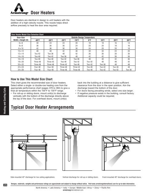
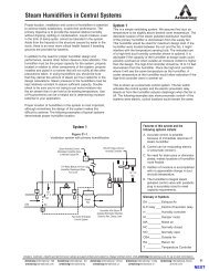
Door HeatersDoor heaters are identical in design to unit heaters with theaddition of a high-velocity nozzle. This nozzle helps directairflow precisely to heat the door area required.Door Heater Model Size Selection ChartDoor SizeOutside Design TemperatureWidth x Height (ft) -40°F -30°F -20°F -10°F 0°F 10°F 20°F 30°F6 x 8 30 24 24 20 18 18 16 148 x 8 36 30 30 24 20 20 18 168 x 10 42 36 30 30 24 20 20 1810 x 12 48 48 42 36 30 30 24 2012 x 14 Two 42 Two 36 48 42 36 36 30 3014 x 16 Two 48 Two 42 Two 36 48 42 42 36 3016 x 18 Two 48 Two 48 Two 42 Two 36 48 48 42 3618 x 20 Three 48 Three 42 Two 48 Two 42 Two 42 48 48 4220 x 22 Three 48 Three 48 Three 42 Two 48 Two 42 Two 36 48 4822 x 24 Four 48 Four 48 Three 48 Three 42 Two 48 Two 42 Two 36 4824 x 26 Four 48 Four 48 Three 48 Three 48 Two 48 Two 42 Two 42 Two 36Heating and Cooling CoilsHow to Use This Model Size Chart:This chart gives the recom mended size of door heaters.Select either a single- or double-row heating core from theappropriate performance chart (pages 378 to 384) to give afinal air temperature within the 100°F to 130°F range.• For roll-up or sliding doors, mount unit(s) to dischargevertically with the bottom of the discharge directly abovethe top of the door. For overhead doors, mount unit(s)Typical Door Heater Arrangementsback into the building at a distance to give sufficientclearance from the door in the open position. Aim thedischarge toward the bottom of the door.• For doors facing prevailing winds, select one size larger.• If negative pressure exists in the building, consult factory.Additional capacity could be required.Side-mounted 45° discharge for low ceiling applications.Vertical discharge for roll-up or sliding doors.Front-mounted 45° discharge for overhead doors.378Designs, materials, weights and performance ratings are approximate and subject to change without notice. Visit www.armstronginternational.com for up-to-date information.North America • Latin America • India • Europe / Middle East / Africa • China • Pacific Rimarmstronginternational.com
Unit HeatersPerformance Data With 2 psig Steam, 60°F Entering Air TemperatureStandard ModelsHigh Outlet Air Temperature ModelsModelSizeHPCommon DataMotorRPMCFMSteel Tube / Aluminum Fin11 FPIMBHLeavingAir (°F)NOTES: Steam pressure as supplied to unit heater. Valve and line losses must be subtractedfrom steam main pressure. Standard CFM measured at 70°F with density of .075 lb/cu ft. Heat load in thousands of Btu/hr.NOTE:Leaving air temperature and MBH from table above must be corrected for steam pressuresother than 2 psig and entering air temperatures other than 60°F.Cond.(lb/hr)Steel Tube / Steel FinStainless Tube / Steel Fin11 FPIMBHLeavingAir (°F)Cond.(lb/hr)Stainless Tube / Stainless Fin10 FPIMBHLeaving Air(°F)101 1/3 1,725 810 36 102 38 29 93 30 17 80 18121 1/3 1,725 1,350 53 97 55 42 89 44 25 77 26141 1/3 1,725 2,590 80 89 83 64 83 66 37 73 39161 1/2 1,725 3,330 102 88 105 87 84 90 51 74 53181 3/4 1,725 4,420 128 87 133 109 83 113 64 73 66201 3/4 1,725 5,430 156 87 161 131 82 136 77 73 79241 1-1/2 1,125 7,020 205 87 212 179 84 185 105 74 108301 2 1,125 10,660 322 88 333 276 84 286 162 74 168361 2 1,125 13,440 406 88 420 351 84 363 206 74 213421 3 870 16,530 536 90 555 444 85 459 261 75 270481 3 870 22,110 692 89 716 593 85 614 349 75 361102 1/3 1,725 700 55 133 57 45 119 47 28 98 29122 1/3 1,725 1,320 88 122 91 71 110 74 44 91 45142 1/3 1,725 1,980 122 117 126 100 107 103 61 88 63162 1/2 1,725 2,910 166 113 171 143 106 148 87 88 90182 3/4 1,725 3,900 212 110 219 182 103 189 110 86 114202 3/4 1,725 4,560 253 111 262 217 104 224 131 87 136242 1-1/2 1,125 6,000 343 113 355 304 107 315 186 89 192302 2 1,125 9,400 548 114 567 477 107 494 291 89 301362 2 1,125 12,160 722 115 747 622 107 643 380 89 393422 3 870 15,160 950 118 983 802 109 830 492 90 509482 3 870 20,040 1,234 117 1,277 1,063 109 1,100 652 90 675Table below lists the correction factors. To determine correction factors falling betweenthose shown, use the next lowest steam pressure and the next highest air temperatureshown.MBH (corrected) = MBH (above) x Correction FactorLAT (corrected) = EAT + (MBH [corrected] x 926/CFM)Condensate Load = MBH (corrected) x 1,000/Latent Heat of SteamCond.(lb/hr)Heating and Cooling CoilsCorrection Factors Based on 2 psig Steam, 60°F Entering AirSteamTemperature of Entering Air (°F)Pressure(psig) -10 0 10 20 30 40 50 60 70 80 90 100Designs, materials, weights and performance ratings are approximate and subject to change without notice. Visit www.armstronginternational.com for up-to-date information.North America • Latin America • India • Europe / Middle East / Africa • China • Pacific Rimarmstronginternational.comSaturatedSteam Temp.(°F)SteamLatent Heat(Btu/lb)2 — — — — — 1.16 1.08 1.00 0.93 0.85 0.78 0.71 219 9665 1.64 1.55 1.46 1.37 1.29 1.21 1.13 1.05 0.97 0.90 0.83 0.76 227 96010 1.73 1.64 1.55 1.46 1.38 1.29 1.21 1.13 1.06 0.98 0.91 0.84 239 95315 1.80 1.71 1.61 1.53 1.44 1.34 1.28 1.19 1.12 1.04 0.97 0.90 250 94520 1.86 1.77 1.68 1.58 1.50 1.42 1.33 1.25 1.17 1.10 1.02 0.95 259 93930 1.97 1.87 1.78 1.68 1.60 1.51 1.43 1.35 1.27 1.19 1.12 1.04 274 92940 2.06 1.96 1.86 1.77 1.68 1.60 1.51 1.43 1.35 1.27 1.19 1.12 286 92050 2.13 2.04 1.94 1.85 1.76 1.67 1.58 1.50 1.42 1.34 1.26 1.19 298 91260 2.20 2.09 2.00 1.90 1.81 1.73 1.64 1.56 1.47 1.39 1.31 1.24 307 90670 2.26 2.16 2.06 1.96 1.87 1.78 1.70 1.61 1.53 1.45 1.37 1.29 316 89875 2.28 2.18 2.09 1.99 1.90 1.81 1.72 1.64 1.55 1.47 1.40 1.32 320 89580 2.31 2.21 2.11 2.02 1.93 1.84 1.75 1.66 1.58 1.50 1.42 1.34 324 89190 2.36 2.26 2.16 2.06 1.97 1.88 1.79 1.71 1.62 1.54 1.46 1.38 331 886100 2.41 2.31 2.20 2.11 2.02 1.93 1.84 1.75 1.66 1.58 1.50 1.42 338 880125 2.51 2.41 2.31 2.21 2.11 2.02 1.93 1.84 1.76 1.68 1.59 1.51 353 868150 2.60 2.50 2.40 2.30 2.20 2.11 2.02 1.93 1.84 1.76 1.67 1.59 366 857200 2.75 2.65 2.55 2.45 2.35 2.25 2.16 2.07 1.98 1.89 1.81 1.72 388 837250 2.87 2.77 2.67 2.57 2.46 2.36 2.27 2.18 2.09 2.01 1.92 1.81 408 820379