2011 All Products Catalog - Armstrong International, Inc.
2011 All Products Catalog - Armstrong International, Inc.
2011 All Products Catalog - Armstrong International, Inc.
- No tags were found...

You also want an ePaper? Increase the reach of your titles
YUMPU automatically turns print PDFs into web optimized ePapers that Google loves.
Unit Heaters
Longer Life in the Harshest EnvironmentsWhen it comes to long life under tough industrial conditions,<strong>Armstrong</strong> is all you need to know about unit heaters.Even in the most severe environments, where coil leaksand corrosion are costly problems, <strong>Armstrong</strong> coils maintainhigh efficiency and output.<strong>Armstrong</strong>: Why and HowThe ability to maintain heat transfer efficiency and resistcorrosion—both internally and externally—is why <strong>Armstrong</strong>unit heaters are uniquely dependable. How we constructthem is your assurance of lasting performance, even insevere operating environments.Consider these measurable benefits at work in your facility:• Heavy gauge enclosures: Fabricated from 14-gaugesteel for protection and durability.• Corrosion-resistant heating cores: Cores are fabricatedin a full range of materials, including steel, stainless steel,copper and others. Special coatings may be applied toincrease resistance to external corrosion. Cores feature allweldedconstruction for durability and ease of repair. Corescan be steam or liquid compatible and can be used forsteam, hot water or glycol heating mediums.• Standard NEMA frame TEFC ball bearing motors:Supplied on all sizes, these heavy-duty motors are totallyenclosed to lock out dirt for smooth performance. Quickaccess to the motor permits easy replacement.• Thick fins and tubes: Constructed of high-strength,corrosion-resistant materials. Fins are available in awide variety of thicknesses and pitches to withstandhigh pressure cleaning without damage or distortion.• Customizing to your needs: Fans range in size from10" to 48", and the wide selection of component materialsmeans long, trouble-free service life.Lightweight coilsdon’t stand achance in harshenvironments.<strong>Armstrong</strong> coilssurvive becausethey’re built astough as yourmeanest application.Heating and Cooling Coils370Designs, materials, weights and performance ratings are approximate and subject to change without notice. Visit www.armstronginternational.com for up-to-date information.North America • Latin America • India • Europe / Middle East / Africa • China • Pacific Rimarmstronginternational.com
Your Steam SpecialistThe first step toward ensuring trouble-free operation isproper unit selection. Your <strong>Armstrong</strong> Representative willhelp you select the right unit heater or door heater for anygiven application.Our expertise as a manufacturer of unit heaters and doorheaters is backed by over 70 years’ experience in steamtrapping, venting and condensate removal. To you, thatmeans a superior product and an <strong>Armstrong</strong> Representativewho understands how to make it work in your steam system.If you’re losing heat transfer due to deteriorating coils,contact your <strong>Armstrong</strong> Representative for a completeapplication analysis. You’ll receive top-quality, reliableproducts from experts who know how to maximize yoursteam system efficiency.Heating and Cooling CoilsDesigns, materials, weights and performance ratings are approximate and subject to change without notice. Visit www.armstronginternational.com for up-to-date information.North America • Latin America • India • Europe / Middle East / Africa • China • Pacific Rimarmstronginternational.com371
Compare the Benefits You Can’t SeeMany of the best reasons to insist on <strong>Armstrong</strong> unit heatersand door heaters are ones you never even see. Componentslike motors, bearings, tubes, enclosures and fins are builtheavy-duty to ensure lasting performance.<strong>Armstrong</strong>’s options for fin material, pitch, height and type,for example, help explain why our heating cores last longerand perform with greater efficiency. These factors all havea bearing on heat transfer. Knowing how to balance theseand other factors is the key to a cost-effective solution. Thatknowledge is perhaps the most important of <strong>Armstrong</strong>’smany hidden benefits.Heating and Cooling CoilsSturdy EnclosuresHeavy-duty enclosures of14-gauge steel provide a rigidstructure. Aluminum, stainlesssteel and specially coatedenclosures are also availableas options.Standard NEMA FrameTEFC Ball Bearing MotorsSupplied on all sizes, thisrugged motor is built tolast in tough industrialenvironments. If replacementis ever needed, motorsare readily available fromindustrial supply dealers,and are easy to install.10"–20" SizeCost-Reducing StrengthThick fins and tubes withstandpressure cleaning withoutdamage or distortion.OSHA-Approved FanGuards Are StandardApplication VersatilityBecause of their heavy-dutyconstruction <strong>Armstrong</strong> unit heatersare used in many applications.These include product coolers, lubeoil coolers, flash steam condensers,hot oil heaters and many others.Corrosion ResistanceFins, tubes and headers are fabricated in awide variety of metals and alloys, includingsteel, stainless steel, copper, aluminum andothers. Tubes and headers are of the samematerial to enhance strength and reduce thechance of leakage due to galvanic corrosion.372Designs, materials, weights and performance ratings are approximate and subject to change without notice. Visit www.armstronginternational.com for up-to-date information.North America • Latin America • India • Europe / Middle East / Africa • China • Pacific Rimarmstronginternational.com
The L fin has a foot atits base and is tensionwound on knurled tubematerial. The L-shapedbase provides a largecontact area between thetube and the fin, ensuringeffective, long-lastingheat transfer. The L finis recommended whentubes and fins are of thesame material.L FinThe keyfin is manufacturedby forming a helical groovein the tube surface, windingthe fin into the groove andpeening the displaced metalfrom the groove against thefin. This means a tight fitbetween the fin and the tube.The keyfin is the superiordesign for dissimilar tube andfin material.KeyfinSteam or Liquid CompatibleCores are available for steam orliquid, allowing units to be appliedin different plant areas wherevarious heating mediums may exist.24"–48" SizeMounting FlexibilityBasic units may be used ineither horizontal or two-wayvertical discharge configurations.The addition or substitution of afour-way vertical louver sectionproduces a square dischargepattern. An optional high-velocitydischarge nozzle allows the unitto be used as a door heater totemper cold air admitted throughopen loading-dock doors. Highvelocitynozzles may also beused in applications requiringgreater mounting heights.High VelocityNozzleHeating and Cooling CoilsFan Size Flexibility<strong>Armstrong</strong> unit heaters and doorheaters are available in fan sizesranging from 10" to 48".Vertical Unit Heater Heat Shield forHigh Temperature ApplicationsSpecial purpose motor: 3b(see page 375)Designs, materials, weights and performance ratings are approximate and subject to change without notice. Visit www.armstronginternational.com for up-to-date information.North America • Latin America • India • Europe / Middle East / Africa • China • Pacific Rimarmstronginternational.com373
Model Number SelectionMODEL NUMBERD A Q – 182 – HS – T 58HOTBREATH TYPED = Dual (2 Fans)See note 4 below.F = FixedSee note 5 below.FIN TYPEA = Aluminum KeyfinB = Heavy Aluminum KeyfinF = Copper KeyfinG = Steel L FinJ = 304 Stainless L FinK = 316 Stainless L FinP = Aluminum PlatefinMOTOR ELECTRICALCHARACTERISTICS (SEE NOTE 2)* 12 = 115-203/16020 = 208/1/6021 = 208/3/6023 = 230-460/3/6058 = 575/3/60*Consult factory for single phase motorabove 1hp. Additional charge could apply.MOTOR TYPEHeating and Cooling CoilsNO. FINS/INCH (SEE NOTE 1)TUBE MATERIALQ = 12 Ga. Steel TubeR = 10 Ga. Steel TubeW = 14 Ga. 304L SS Tube(see note 3)Y = 14 Ga. 316L Tube(see note 3)T = Totally EnclosedFab CooledX = Explosion ProofM = Severe Duty(3-phase motors only)CORESS = Steam CoreL = Liquid CoreMODEL SIZEFan Diameter (in)No. Rows of Tubes in CoreNotes:1. If the number of fins/inch is standard, the numbersbetween fin type and tube material will be missing.2. If dual or triple voltage motors are supplied, the voltageshown on the model number will be the lowest specified.It is the responsibility of the installer to ensure that themotor is wired correctly in accordance with the motormanufacturer’s instructions to preclude damage.DISCHARGE TYPEH = 2 Way Louver(Usually Hor. Discharge)V = 4 Way Louver(Usually Vert. Discharge)N = High Velocity Nozzle(Std. on Door Heaters)3. May be substituted with Sch. 10 SS pipe.4. Add prefix ‘D’ for dual units (2 fans on wider core).For standard unit with one fan, the Hotbreath type willbe missing.5. F Models includes larger motors, cleanout lip, ports forsensors.374Designs, materials, weights and performance ratings are approximate and subject to change without notice. Visit www.armstronginternational.com for up-to-date information.North America • Latin America • India • Europe / Middle East / Africa • China • Pacific Rimarmstronginternational.com
Material SpecificationsUnit Heater Core Material Specifications1" OD Tubes Fins Headers ConnectionsMaterialMin. WallMinimumMinimumMinimumMaterial Type FPIMaterialMaterialThicknessThicknessThicknessThicknessStandard MaterialsSteel .109" Steel L-Foot 11 .024" Steel .145" Steel .133"Steel .109" Aluminum Keyfin 11 .020" Steel .145" Steel .133"Special Order MaterialsSteel .109" Copper Keyfin 11 .016" Steel .145" Steel .133"Stainless .083" Steel L-Foot 11 .024" Stainless .109" Stainless .109"Stainless .083" Stainless L-Foot 10 .020" Stainless .109" Stainless .109"Stainless .083" Aluminum Keyfin 11 .020" Stainless .109" Stainless .109"Stainless .083" Copper Keyfin 11 .016" Stainless .109" Stainless .109"NOTE: Stainless tubes available in either 304L or 316L.Options:• Special coatings such as powder coat epoxy, baked phenolic or hot dipgalvanizing.• Thicker tube walls.Design Pressures and Testing SpecificationsCore design pressure is 350 psig @ saturated steam temperature.Standard testing pressure at 525 psig. Higher pressure ratings are available upon request.EnclosuresEnclosures, louvers and high-velocity nozzles arefabricated from 14 ga galvanized steel, finished in grayenamel. Available material options include stainless steelor aluminum. Epoxy coatings and other protective finishesare available.Motor SpecificationsStandard MotorsConstruction:TEFC, NEMA frame, rigid mount, continuous duty,NEMA B design, Class B insulation, 1.0 service factor,sealed ball bearings and steel frame.FansFans are of stamped aluminum with steel hubs and spiderson unit sizes 30" and smaller. Cast aluminum fans arefurnished on unit sizes 36" and larger.Fan guards are OSHA-approved and constructed of brightzinc plated steel wire.b. Three phase integral HP. Available with 1.15 servicefactor, Class F insulation, cast iron frame, end bells,fan cover and conduit box, stain less steel shaft, shaftflingers and stainless steel name plate, epoxy coated.(Explosion proof motor S.F. = 1.0).Heating and Cooling CoilsElectrical Characteristics:Single Phase (standard through 3/4 HP—optional extra cost1-1/2 HP) 115, 208 & 230 volts. Three Phase (all sizes)—208, 230, 460 & 575 volts.Special Purpose Motors1. Explosion-proof motors are available in all horsepowersand voltages. They are suitable for Class I Group D andClass II Groups F & G service.2. Environmentally Protected. Known as “Mill & Chemical,”“Severe” and “Hostile” duty motors.a. Three phase 1/2 & 3/4 HP. Available with 1.15 servicefactor, Class F insulation, steel frame, cast iron endbells and conduit box, phosphatized or stainless steelshaft, shaft flingers and stainless steel nameplate.3. High Temperature Applicationsa. For horizontal discharge applications where highambient temperatures are encountered (typically140°F–150°F, 165°F maximum), motor HP orinsulation class must be increased. Consult factory.b. For vertical units with on/off fan operation:Heating Medium Temperature300°F–375°FClass F Insulation & Heat Shield375°F & OverClass H Insulation & Heat Shield4. Washdown duty motors also available.Designs, materials, weights and performance ratings are approximate and subject to change without notice. Visit www.armstronginternational.com for up-to-date information.North America • Latin America • India • Europe / Middle East / Africa • China • Pacific Rimarmstronginternational.com375
Selecting Unit HeatersA multi-step process is required to select the proper size,type and number of unit heaters to adequately heat aparticular building. The process consists of the following steps:1. Estimate the building heat loss.2. Preliminarily select the number and type(s) of heaters toproperly cover the area to be heated.3. Select specific models and calculate the actual performanceof equipment selected using actual heating mediumconditions and inlet air temperatures.4. Calculate actual throws, spreads and mounting heightsand check to see that they will allow for completecoverage of the area to be heated.B. Calculate the area of walls and roofs that are exposed tooutside temperature:Exposed area (EA) = wall length (ft) x average ceilingheight (ft) + floor area (sq ft)C. Total heat load (MBH) =( )V EA ∆ T+ x25 4 1000WhereV = Building Volume (cu-ft)EA = Exposed Wall & Roof Area (ft²)∆T = Inside Design Temperature (F) –Outside Design Temperature (F)Heating and Cooling Coils5. If necessary, adjust selection and repeat steps 2 through 4.Estimating Heat LossThe ASHRAE Handbook of Fundamentals should beconsulted to determine heat losses, taking into accountspecific building features. However, for an approximation ofthe heat loss from a typical modern industrial building, thefollowing formula may be used.With heated area size and outside design temperatures given:A. Calculate the volume of the building in cubic feet:Volume (cu ft) = floor length (ft) x floor width (ft)x average ceiling height (ft)Typical ArrangementsSelection of Number, Type(s) and Locationof Unit HeatersWith the total heat loss calculated, the next step is todetermine the number, type(s) and location of unit heaters.First, look at the layout of the building. From that, determinethe general arrangement of the unit heaters. Some typicallayouts are shown below, but any given arrangement shouldbe tailored to the particular building. Some general rules toconsider follow:1. Horizontal unit heaters are used as a means to heatoutside walls and should be directed to discharge towardor along walls to provide a wiping effect. Horizon taldischarge units are generally sufficient to adequately heatmost buildings except those with very large central floorareas or very high ceilings.Horizontal unit heaters provide a sweeping effect over outside walls and aresufficient to heat most buildings except those with large central floor areas.Four-way vertical discharge units are used to heat large central areas andbuildings with high ceilings or buildings with large heat loss through the ceiling.376Designs, materials, weights and performance ratings are approximate and subject to change without notice. Visit www.armstronginternational.com for up-to-date information.North America • Latin America • India • Europe / Middle East / Africa • China • Pacific Rimarmstronginternational.com
2. Vertical unit heaters are used when a direct downwarddischarge to heat large central areas is needed. Theymay also be used if the mounting heights and throwsallow for wiping of the walls with their discharge air. Thedischarge may be arranged for two-way airflow or fourwayairflow with the addition or substitution of a four-waydischarge section. A rectangular building might only needtwo-way discharge, whereas a square building would bebetter covered with a four-way arrangement.Vertical units are also used in buildings with high ceilingsor where roof heat losses are exceptionally high. Hot airfrom the roof area is drawn into the units and directeddown to floor level, minimizing temperature gradients andreducing fuel consumption.If fitted with a high-velocity discharge nozzle, units can beused at higher than normal mounting heights.6. Unit heaters should be located to blow into open spacessuch as aisles and along exterior walls rather than directlyat personnel.7. The mounting heights and throws specified on page 384and corrected for outlet air temperature should be followed.Improper mounting height distance will result in poor heatdistribution and reduced comfort.Once the general layout has been determined, you canbegin selecting the type of model required. First, select anydoor heaters that may be required. Then, select any verticalunit heaters. If the vertical unit heaters are to be directedtoward center floor areas and used in conjunction withhorizontal units, calculate the percentage of the total areait is intended to cover and divide that by 2. That will giveyou the percentage of the total heat that is required fromthe vertical units.3. Door heaters simply use a high-velocity discharge nozzleto increase the air velocity to reach those areas thatare hard to heat. These heaters can provide blankets ofwarm air to heat large open-loading doorways or busyentryways. They are also ideal for heating wide openplant areas. If door heater fans are activated only whendoors are open, their Btu output should not be consideredas part of the heat loss makeup. See page 378 for doorheater selection guidelines.4. Units should be directed toward the areas of greatest heatloss. Outside doorways and exposed windows requiremore careful consideration.5. Unit heater airstreams should be minimally obstructed toallow for greatest heat distribution.Lastly, select the horizontal units. The remaining heat loadto be provided is divided by the number of units desired.Here your choice may be between a number of smaller unitsor fewer larger units. Notice that as the units increase in sizeand heating capacity their throw also increases. Generally,fewer larger units will result in the most economicalinstallation as long as full coverage is provided.After completing this preliminary selection process, you cancalculate the actual throws, spreads and mounting heightsto ensure the area will be adequately heated. If you findthat the required coverage cannot be met with your initialselections, recalculate coverage by adjusting unit size ornumber of units.Heating and Cooling CoilsHigh-velocity vertical unit heaters and door heaters are used to reach hard-to-heat areas or to provide blankets of warm air to large open areas such asloading dock doors.Designs, materials, weights and performance ratings are approximate and subject to change without notice. Visit www.armstronginternational.com for up-to-date information.North America • Latin America • India • Europe / Middle East / Africa • China • Pacific Rimarmstronginternational.com377
Door HeatersDoor heaters are identical in design to unit heaters with theaddition of a high-velocity nozzle. This nozzle helps directairflow precisely to heat the door area required.Door Heater Model Size Selection ChartDoor SizeOutside Design TemperatureWidth x Height (ft) -40°F -30°F -20°F -10°F 0°F 10°F 20°F 30°F6 x 8 30 24 24 20 18 18 16 148 x 8 36 30 30 24 20 20 18 168 x 10 42 36 30 30 24 20 20 1810 x 12 48 48 42 36 30 30 24 2012 x 14 Two 42 Two 36 48 42 36 36 30 3014 x 16 Two 48 Two 42 Two 36 48 42 42 36 3016 x 18 Two 48 Two 48 Two 42 Two 36 48 48 42 3618 x 20 Three 48 Three 42 Two 48 Two 42 Two 42 48 48 4220 x 22 Three 48 Three 48 Three 42 Two 48 Two 42 Two 36 48 4822 x 24 Four 48 Four 48 Three 48 Three 42 Two 48 Two 42 Two 36 4824 x 26 Four 48 Four 48 Three 48 Three 48 Two 48 Two 42 Two 42 Two 36Heating and Cooling CoilsHow to Use This Model Size Chart:This chart gives the recom mended size of door heaters.Select either a single- or double-row heating core from theappropriate performance chart (pages 378 to 384) to give afinal air temperature within the 100°F to 130°F range.• For roll-up or sliding doors, mount unit(s) to dischargevertically with the bottom of the discharge directly abovethe top of the door. For overhead doors, mount unit(s)Typical Door Heater Arrangementsback into the building at a distance to give sufficientclearance from the door in the open position. Aim thedischarge toward the bottom of the door.• For doors facing prevailing winds, select one size larger.• If negative pressure exists in the building, consult factory.Additional capacity could be required.Side-mounted 45° discharge for low ceiling applications.Vertical discharge for roll-up or sliding doors.Front-mounted 45° discharge for overhead doors.378Designs, materials, weights and performance ratings are approximate and subject to change without notice. Visit www.armstronginternational.com for up-to-date information.North America • Latin America • India • Europe / Middle East / Africa • China • Pacific Rimarmstronginternational.com
Unit HeatersPerformance Data With 2 psig Steam, 60°F Entering Air TemperatureStandard ModelsHigh Outlet Air Temperature ModelsModelSizeHPCommon DataMotorRPMCFMSteel Tube / Aluminum Fin11 FPIMBHLeavingAir (°F)NOTES: Steam pressure as supplied to unit heater. Valve and line losses must be subtractedfrom steam main pressure. Standard CFM measured at 70°F with density of .075 lb/cu ft. Heat load in thousands of Btu/hr.NOTE:Leaving air temperature and MBH from table above must be corrected for steam pressuresother than 2 psig and entering air temperatures other than 60°F.Cond.(lb/hr)Steel Tube / Steel FinStainless Tube / Steel Fin11 FPIMBHLeavingAir (°F)Cond.(lb/hr)Stainless Tube / Stainless Fin10 FPIMBHLeaving Air(°F)101 1/3 1,725 810 36 102 38 29 93 30 17 80 18121 1/3 1,725 1,350 53 97 55 42 89 44 25 77 26141 1/3 1,725 2,590 80 89 83 64 83 66 37 73 39161 1/2 1,725 3,330 102 88 105 87 84 90 51 74 53181 3/4 1,725 4,420 128 87 133 109 83 113 64 73 66201 3/4 1,725 5,430 156 87 161 131 82 136 77 73 79241 1-1/2 1,125 7,020 205 87 212 179 84 185 105 74 108301 2 1,125 10,660 322 88 333 276 84 286 162 74 168361 2 1,125 13,440 406 88 420 351 84 363 206 74 213421 3 870 16,530 536 90 555 444 85 459 261 75 270481 3 870 22,110 692 89 716 593 85 614 349 75 361102 1/3 1,725 700 55 133 57 45 119 47 28 98 29122 1/3 1,725 1,320 88 122 91 71 110 74 44 91 45142 1/3 1,725 1,980 122 117 126 100 107 103 61 88 63162 1/2 1,725 2,910 166 113 171 143 106 148 87 88 90182 3/4 1,725 3,900 212 110 219 182 103 189 110 86 114202 3/4 1,725 4,560 253 111 262 217 104 224 131 87 136242 1-1/2 1,125 6,000 343 113 355 304 107 315 186 89 192302 2 1,125 9,400 548 114 567 477 107 494 291 89 301362 2 1,125 12,160 722 115 747 622 107 643 380 89 393422 3 870 15,160 950 118 983 802 109 830 492 90 509482 3 870 20,040 1,234 117 1,277 1,063 109 1,100 652 90 675Table below lists the correction factors. To determine correction factors falling betweenthose shown, use the next lowest steam pressure and the next highest air temperatureshown.MBH (corrected) = MBH (above) x Correction FactorLAT (corrected) = EAT + (MBH [corrected] x 926/CFM)Condensate Load = MBH (corrected) x 1,000/Latent Heat of SteamCond.(lb/hr)Heating and Cooling CoilsCorrection Factors Based on 2 psig Steam, 60°F Entering AirSteamTemperature of Entering Air (°F)Pressure(psig) -10 0 10 20 30 40 50 60 70 80 90 100Designs, materials, weights and performance ratings are approximate and subject to change without notice. Visit www.armstronginternational.com for up-to-date information.North America • Latin America • India • Europe / Middle East / Africa • China • Pacific Rimarmstronginternational.comSaturatedSteam Temp.(°F)SteamLatent Heat(Btu/lb)2 — — — — — 1.16 1.08 1.00 0.93 0.85 0.78 0.71 219 9665 1.64 1.55 1.46 1.37 1.29 1.21 1.13 1.05 0.97 0.90 0.83 0.76 227 96010 1.73 1.64 1.55 1.46 1.38 1.29 1.21 1.13 1.06 0.98 0.91 0.84 239 95315 1.80 1.71 1.61 1.53 1.44 1.34 1.28 1.19 1.12 1.04 0.97 0.90 250 94520 1.86 1.77 1.68 1.58 1.50 1.42 1.33 1.25 1.17 1.10 1.02 0.95 259 93930 1.97 1.87 1.78 1.68 1.60 1.51 1.43 1.35 1.27 1.19 1.12 1.04 274 92940 2.06 1.96 1.86 1.77 1.68 1.60 1.51 1.43 1.35 1.27 1.19 1.12 286 92050 2.13 2.04 1.94 1.85 1.76 1.67 1.58 1.50 1.42 1.34 1.26 1.19 298 91260 2.20 2.09 2.00 1.90 1.81 1.73 1.64 1.56 1.47 1.39 1.31 1.24 307 90670 2.26 2.16 2.06 1.96 1.87 1.78 1.70 1.61 1.53 1.45 1.37 1.29 316 89875 2.28 2.18 2.09 1.99 1.90 1.81 1.72 1.64 1.55 1.47 1.40 1.32 320 89580 2.31 2.21 2.11 2.02 1.93 1.84 1.75 1.66 1.58 1.50 1.42 1.34 324 89190 2.36 2.26 2.16 2.06 1.97 1.88 1.79 1.71 1.62 1.54 1.46 1.38 331 886100 2.41 2.31 2.20 2.11 2.02 1.93 1.84 1.75 1.66 1.58 1.50 1.42 338 880125 2.51 2.41 2.31 2.21 2.11 2.02 1.93 1.84 1.76 1.68 1.59 1.51 353 868150 2.60 2.50 2.40 2.30 2.20 2.11 2.02 1.93 1.84 1.76 1.67 1.59 366 857200 2.75 2.65 2.55 2.45 2.35 2.25 2.16 2.07 1.98 1.89 1.81 1.72 388 837250 2.87 2.77 2.67 2.57 2.46 2.36 2.27 2.18 2.09 2.01 1.92 1.81 408 820379
Unit HeatersHeating and Cooling Coils380Performance Data With 200°F Water, 60°F Entering Air TemperatureStandard ModelsLow Outlet Air Temperature ModelsModelSize102 1/3Common DataMotorCFM WaterHP RPM Temp.Drop1,725700122 1/3 1,320142 1/3 1,980162 1/2 2,910182 3/4 3,900202 3/4 4,5601,125242 1-1/2 6,000302 2 9,400362 2 12,160422 387015,160482 3 20,040101 1/31,725810121 1/3 1,350141 1/3 2,590161 1/2 3,330181 3/4 4,420201 3/4 5,4301,125241 1-1/2 7,020301 2 10,660361 2 13,440421 387016,530481 3 22,110Steel Tube / Aluminum Fin11 FPIMBHLeavingAir (°F)USGPMPressureDrop(ft wg)WaterTemp.DropSteel Tube / Steel FinStainless Tube / Steel Fin11 FPIDesigns, materials, weights and performance ratings are approximate and subject to change without notice. Visit www.armstronginternational.com for up-to-date information.North America • Latin America • India • Europe / Middle East / Africa • China • Pacific Rimarmstronginternational.comMBHLeavingAir (°F)USGPMPressureDrop(ft wg)WaterTemp.DropStainless Tube / Stainless Fin10 FPIMBHLeavingAir (°F)USGPMPressureDrop(ft wg)10 45 119 8.9 2.01 10 33 104 6.7 1.02 10 25 93 5.0 .5420 39 112 3.9 .39 20 29 99 2.9 .20 20 22 89 2.2 .1030 34 106 2.3 .13 30 25 93 1.7 .07 30 19 86 1.3 .0410 62 103 12.4 4.01 10 52 96 10.4 1.87 10 38 87 7.6 .9520 55 99 5.5 .79 20 46 92 4.6 .37 20 34 84 3.4 .1930 49 94 3.2 .27 30 40 88 2.7 .13 30 30 81 2.0 .0710 90 102 18.0 1.95 10 76 96 15.2 .94 10 55 86 11.0 .4620 78 97 7.8 .37 20 66 91 6.6 .18 20 48 82 4.8 .0930 67 92 4.5 .12 30 57 87 3.8 .06 30 42 79 2.8 .0310 119 98 23.9 2.77 10 97 91 19.3 1.24 10 70 82 14.0 .6220 105 94 10.5 .54 20 85 87 8.5 .24 20 61 80 6.1 .1230 92 89 6.1 .18 30 75 84 5.0 .08 30 54 77 3.6 .0410 156 97 31.2 3.89 10 132 91 26.5 1.77 10 94 82 18.9 .8520 137 93 13.7 .75 20 116 88 11.6 .34 20 83 80 8.3 .1730 121 89 8.1 .26 30 102 84 6.8 .12 30 74 78 4.9 .0610 190 99 38.0 4.88 10 161 93 32.2 2.25 10 115 83 23.1 1.0820 170 95 17.0 .97 20 144 89 14.4 .45 20 103 81 10.3 .2230 150 91 10.0 .34 30 127 86 8.4 .15 30 91 79 6.1 .0810 284 104 56.8 8.39 10 237 97 47.4 3.87 10 169 86 33.7 1.8220 258 100 25.8 1.73 20 214 93 21.4 .79 20 153 84 15.3 .3730 232 96 15.5 .62 30 196 90 13.1 .29 30 137 81 9.2 .1315 437 103 58.2 4.10 10 380 97 75.9 6.36 10 267 86 53.4 2.9420 416 101 41.6 2.79 20 345 94 34.5 1.31 20 245 84 24.5 .6230 381 98 25.4 1.04 30 315 91 21.0 .49 30 222 82 14.8 .2315 575 104 76.7 5.84 10 491 97 98.2 9.20 10 352 87 70.4 4.4120 552 102 55.2 4.19 20 452 95 45.3 1.96 20 324 85 32.4 .9430 506 99 33.7 1.56 30 419 92 27.9 .74 30 297 83 19.8 .3510 748 106 149.7 3.05 10 612 97 122.5 1.43 10 452 88 90.4 .7020 675 101 67.5 .62 20 552 94 55.2 .29 20 406 85 40.6 .1430 603 97 40.2 .22 30 490 90 32.6 .10 30 364 82 24.2 .0510 989 106 197.8 4.36 10 820 98 164.1 1.97 10 547 88 119.5 .9820 892 101 89.2 .89 20 745 94 74.5 .41 20 539 85 53.9 .2030 801 97 53.4 .32 30 667 91 44.4 .14 30 487 83 32.5 .0710 28 92 5.6 3.80 10 21 84 4.2 2.09 10 16 78 3.1 .8620 25 88 2.5 .74 20 19 82 1.9 .43 20 14 76 1.4 .1730 22 85 1.5 .26 30 17 79 1.1 .15 30 12 74 .8 .0610 41 88 8.2 6.20 10 32 82 6.3 3.54 10 23 76 4.6 1.420 36 85 3.7 1.24 20 29 80 2.9 .73 20 20 74 2.0 .2830 32 82 2.2 .44 30 25 77 1.7 .25 30 18 73 1.2 .1010 60 81 12.0 3.13 10 47 77 9.5 1.85 10 33 72 6.6 .6820 52 79 5.2 .58 20 41 75 4.1 .35 20 29 70 2.9 .1330 45 76 3.0 .20 30 36 73 2.4 .12 30 25 69 1.7 .0410 76 81 15.3 4.15 10 63 78 12.7 2.19 10 45 73 9.0 .8420 67 79 6.7 .80 20 57 76 5.7 .44 20 40 71 4.0 .1630 58 76 3.9 .27 30 49 74 3.3 .15 30 35 70 2.3 .0610 97 80 19.5 5.62 10 81 77 16.1 3.03 10 57 72 11.4 1.1520 86 78 8.6 1.09 20 73 75 7.3 .61 20 50 71 5.0 .2230 75 76 5.0 .37 30 64 74 4.3 .21 30 45 69 3.0 .0810 119 80 23.8 7.14 10 98 77 19.6 3.85 10 69 72 13.7 1.4420 106 78 10.6 1.40 20 88 75 8.8 .78 20 62 71 6.2 .2930 94 76 6.3 .49 30 79 74 5.3 .28 30 55 69 3.7 .1015 160 81 21.4 4.47 10 136 78 27.1 4.76 10 95 73 19.0 2.1620 153 80 15.3 2.28 20 123 76 12.3 .97 20 86 71 8.6 .4530 137 78 9.1 .80 30 111 75 7.4 .36 30 78 70 5.2 .1615 249 82 33.2 6.66 10 208 78 41.7 7.22 10 149 73 29.7 3.4120 236 81 23.6 3.37 20 190 77 19.0 1.50 20 137 72 13.7 .7430 215 79 14.4 1.25 30 173 75 11.5 .55 30 124 71 8.3 .2715 327 83 43.6 9.87 10 269 79 53.7 10.43 10 190 73 38.0 4.8820 312 82 31.2 5.07 20 247 77 24.7 2.20 20 177 72 17.7 1.0630 285 80 19.0 1.87 30 226 76 15.1 .82 30 161 71 10.7 .3910 425 84 85.0 3.74 10 337 79 67.5 1.66 10 234 73 46.8 .7420 380 81 38.0 .75 20 300 77 30.0 .33 20 211 72 21.1 .1530 336 79 22.4 .26 30 266 75 17.7 .11 30 186 70 12.4 .0510 559 83 111.8 5.33 10 451 79 90.3 2.30 10 315 73 63.0 1.0320 502 81 50.2 1.07 20 406 77 40.6 .46 20 284 72 28.4 .2130 451 79 30.1 .39 30 365 75 24.4 .17 30 253 71 16.9 .07
Unit HeatersNOTES: Water temperature at the unit heater. Standard CFM measured at 70°F with density of .075 lb/cu ft. Heat load in thousands of Btu/hr.NOTE:Leaving air temperature and MBH from table on previous page mustbe corrected for water temperatures other than 200°F and entering airtemperatures other than 60°F. Liquid flow rates and pressure drops arenot corrected.Table below lists the correction factors. To determine correction factors fallingbetween those shown, use the next lowest water temperature and the nexthighest entering air temperature shown.MBH (corrected) = MBH (from page 380) x Correction FactorLAT (corrected) = EAT + (MBH (corrected) x 926/CFM)Water ∆T = MBH (corrected) x 2.00/USGPMCorrection Factors Based on 200°F Entering Water, 60°F Entering AirEntering WaterTemperature of Entering Air (°F)Temp. (°F) 0 10 20 30 40 50 60 70 80 90 100160 1.23 1.14 1.05 0.96 0.88 0.80 0.72 0.63 0.57 0.48 0.41170 1.31 1.21 1.12 1.04 0.95 0.87 0.79 0.70 0.63 0.55 0.48180 1.38 1.29 1.20 1.11 1.02 0.94 0.86 0.77 0.70 0.62 0.55190 1.46 1.36 1.27 1.18 1.10 1.01 0.93 0.85 0.77 0.69 0.62200 1.54 1.44 1.35 1.26 1.17 1.09 1.00 0.92 0.84 0.76 0.68210 1.61 1.52 1.42 1.33 1.25 1.16 1.07 0.99 0.91 0.83 0.75220 1.69 1.59 1.50 1.41 1.32 1.23 1.14 1.06 0.98 0.90 0.82230 1.77 1.67 1.57 1.48 1.39 1.30 1.22 1.13 1.05 0.97 0.89240 1.84 1.75 1.65 1.55 1.47 1.37 1.29 1.20 1.12 1.04 0.96250 1.92 1.82 1.72 1.63 1.54 1.45 1.36 1.27 1.19 1.11 1.03Heating and Cooling CoilsDesigns, materials, weights and performance ratings are approximate and subject to change without notice. Visit www.armstronginternational.com for up-to-date information.North America • Latin America • India • Europe / Middle East / Africa • China • Pacific Rimarmstronginternational.com381
Unit HeatersHeating and Cooling Coils382Performance Data With 300°F Water, 60°F Entering Air TemperatureStandard ModelsLow Outlet Air Temperature ModelsModelSize102 1/3Common DataMotorCFM WaterHP RPM Temp.Drop1,725700122 1/3 1,320142 1/3 1,980162 1/2 2,910182 3/4 3,900202 3/4 4,5601,125242 1-1/2 6,000302 2 9,400362 2 12,160422 387015,160482 3 20,040101 1/31,725810121 1/3 1,350141 1/3 2,590161 1/2 3,330181 3/4 4,420201 3/4 5,4301,125241 1-1/2 7,020301 2 10,660361 2 13,440421 387016,530481 3 22,110Steel Tube / Aluminum Fin11 FPIMBHLeavingAir (°F)USGPMPressureDrop(ft wg)WaterTemp.DropSteel Tube / Steel FinStainless Tube / Steel Fin11 FPIDesigns, materials, weights and performance ratings are approximate and subject to change without notice. Visit www.armstronginternational.com for up-to-date information.North America • Latin America • India • Europe / Middle East / Africa • China • Pacific Rimarmstronginternational.comMBHLeavingAir (°F)USGPMPressureDrop(ft wg)WaterTemp.DropStainless Tube / Stainless Fin10 FPIMBHLeavingAir (°F)USGPMPressureDrop(ft wg)40 69 151 3.4 .30 40 51 127 2.5 .15 40 38 111 1.9 .0860 64 145 2.1 .16 60 45 119 1.5 .05 60 34 106 1.2 .0380 60 140 1.5 .06 80 40 113 1.0 .02 80 30 99 .7 .0140 96 128 4.8 .61 40 79 116 4.0 .25 40 59 101 2.9 .1460 86 120 2.9 .21 60 71 110 2.4 .10 60 53 97 1.8 .0580 75 113 1.9 .09 80 62 104 1.6 .04 80 47 93 1.2 .0240 137 124 6.8 .28 40 116 114 5.8 .14 40 84 99 4.2 .0760 120 116 4.0 .10 60 101 107 3.4 .05 60 74 95 2.5 .0280 103 108 2.6 .04 80 86 100 2.1 .02 80 63 90 4.6 .0140 185 119 9.2 .41 30 148 107 7.4 .18 40 108 94 5.4 .0960 162 112 5.4 .14 60 131 102 4.4 .06 60 94 90 3.1 .0380 140 105 3.5 .06 80 114 96 2.8 .03 80 82 86 2.1 .0140 240 117 12.0 .58 40 203 108 10.2 .26 40 146 95 7.3 .1360 213 111 7.1 .20 60 179 103 6.0 .09 60 129 91 4.3 .0480 185 104 4.6 .09 80 158 97 3.9 .04 80 113 87 2.8 .0240 296 120 14.8 .74 40 251 111 12.5 .34 40 178 96 8.9 .1660 264 114 8.8 .26 60 224 106 7.5 .12 60 161 93 5.4 .0680 233 107 5.8 .11 80 197 100 4.9 .05 80 141 89 3.5 .0340 444 129 22.2 1.00 40 373 118 18.6 .60 40 264 101 13.2 .2860 405 123 13.5 .37 60 336 112 11.2 .22 60 238 97 7.9 .1080 363 116 9.1 .17 80 301 107 7.5 .10 80 214 93 5.4 .0540 721 131 36.0 1.57 40 596 119 29.8 .98 40 421 102 21.1 .4660 660 125 22.0 .59 60 543 114 18.1 .36 60 383 98 12.8 .1780 599 119 15.0 .27 80 493 109 12.3 .17 80 348 94 8.7 .0840 950 132 47.5 2.24 40 781 120 39.1 1.46 40 557 102 27.8 .6960 873 127 29.1 .84 60 714 114 23.8 .54 60 511 99 17.0 .2680 799 121 20.0 .40 80 654 110 16.4 .25 80 465 95 11.6 .1240 1,167 131 58.4 .32 40 956 118 47.8 .22 40 704 103 35.2 .1160 1,048 124 34.9 .12 60 856 112 28.5 .08 60 632 99 21.1 .0480 933 117 23.3 .05 80 763 107 19.1 .03 80 560 94 14.0 .0240 1,543 131 77.2 .45 40 1,294 120 64.7 .31 40 939 103 47.0 .1560 1,392 124 46.4 .16 60 1,158 114 38.6 .11 60 848 99 28.3 .0580 1,255 118 31.4 .07 80 1,045 108 26.1 .05 80 753 95 18.8 .0240 43 109 2.1 .56 40 33 98 1.7 .32 40 24 88 1.2 .1360 38 104 1.3 .20 60 30 94 1.0 .11 60 21 85 .7 .0580 34 98 .8 .09 80 26 90 .7 .05 80 19 82 .5 .0240 63 103 3.2 .93 40 49 94 2.5 .53 40 35 84 1.8 .2160 57 99 1.9 .33 60 45 91 1.5 .20 60 32 82 1.1 .0880 50 95 1.3 .15 80 39 87 1.0 .08 80 28 79 .7 .0340 91 93 4.6 .45 40 71 86 3.6 .26 40 50 78 2.5 .1060 80 89 2.7 .15 60 63 83 2.1 .09 60 44 76 1.5 .0380 69 85 1.7 .06 80 55 80 1.4 .04 80 38 74 1.0 .0140 117 93 5.8 .61 30 98 87 4.9 .33 40 69 79 3.5 .1360 103 89 3.4 .21 60 87 84 2.9 .12 60 61 77 2.0 .0480 89 85 2.2 .09 80 77 81 1.9 .05 80 54 75 1.4 .0240 150 91 7.5 .83 40 126 86 6.3 .46 40 87 78 4.4 .1760 133 88 4.4 .29 60 112 83 3.7 .16 60 78 76 2.6 .0680 117 84 2.9 .18 80 99 81 2.5 .07 80 69 74 1.7 .0340 185 92 9.2 1.07 40 153 86 7.6 .58 40 107 78 5.4 .2260 164 88 5.5 .38 60 138 84 4.6 .21 60 96 76 3.2 .0880 144 85 3.6 .16 80 122 81 3.1 .09 80 84 74 2.1 .0340 263 95 13.2 1.68 40 214 88 10.7 .74 40 149 80 7.4 .3360 239 92 8.0 .62 60 192 85 6.4 .26 60 135 78 4.5 .1280 212 88 5.3 .27 80 173 83 4.3 .12 80 121 76 3.0 .0540 408 96 20.4 2.53 40 329 89 16.7 1.13 40 234 80 11.7 .5460 372 92 12.4 .93 60 298 86 9.9 .41 60 213 79 7.1 .2080 334 89 8.4 .42 80 269 83 6.7 .19 80 192 77 4.8 .0940 537 97 26.9 3.75 40 425 89 21.3 1.64 40 302 81 15.1 .7760 494 94 16.5 1.41 60 389 87 13.0 .61 60 276 79 9.2 .2980 447 91 11.2 .65 80 356 85 8.9 .29 80 250 77 6.2 .1340 661 97 33.0 .57 40 528 90 26.4 .25 40 362 80 18.1 .1160 586 93 19.5 .20 60 466 86 15.5 .09 60 323 78 10.8 .0480 520 89 13.0 .09 80 411 83 10.3 .04 80 286 76 7.1 .0230 876 97 43.8 .82 40 700 89 35.0 .35 40 492 81 24.6 .1660 783 93 26.1 .29 60 630 86 21.0 .12 60 442 79 14.7 .0680 693 89 17.3 .13 80 564 84 14.1 .06 80 392 76 9.8 .02
Unit HeatersNOTES: Water temperature at the unit heater. Standard CFM measured at 70°F with density of .075 lb/cu ft. Heat load in thousands of Btu/hr.NOTE:Leaving air temperature and MBH from table on previous page mustbe corrected for water temperatures other than 300°F and entering airtemperatures other than 60°F. Liquid flow rates and pressure drops arenot corrected.Table below lists the correction factors. To determine correction factors fallingbetween those shown, use the next lowest water temperature and the nexthighest entering air temperature shown.MBH (corrected) = MBH (from page 382) x Correction FactorLAT (corrected) = EAT + (MBH [corrected] x 926/CFM)Water ∆T = MBH (corrected) x 2.08/USGPMCorrection Factors Based on 300°F Entering Water, 60°F Entering AirEntering WaterTemperature of Entering Air (°F)Temp. (°F) 0 10 20 30 40 50 60 70 80 90 100260 1.15 1.10 1.04 0.99 0.94 0.88 0.83 0.78 0.73 0.69 0.64270 1.19 1.14 1.08 1.03 0.98 0.93 0.88 0.82 0.78 0.73 0.68280 1.23 1.18 1.13 1.08 1.02 0.97 0.92 0.87 0.82 0.77 0.72290 1.27 1.22 1.17 1.12 1.07 1.01 0.96 0.91 0.86 0.81 0.76300 1.31 1.26 1.21 1.16 1.11 1.05 1.00 0.95 0.90 0.85 0.80310 1.35 1.30 1.25 1.21 1.15 1.10 1.04 0.99 0.94 0.89 0.84320 1.41 1.36 1.30 1.26 1.19 1.14 1.09 1.03 0.98 0.93 0.88330 1.45 1.40 1.34 1.30 1.23 1.18 1.13 1.07 1.02 0.97 0.92340 1.49 1.44 1.39 1.34 1.27 1.22 1.17 1.11 1.06 1.01 0.95350 1.54 1.48 1.43 1.38 1.33 1.26 1.21 1.15 1.10 1.05 1.00360 1.58 1.52 1.47 1.42 1.36 1.30 1.25 1.20 1.14 1.09 1.04370 1.62 1.57 1.51 1.46 1.40 1.35 1.29 1.24 1.18 1.13 1.08380 1.66 1.61 1.55 1.50 1.44 1.39 1.33 1.28 1.22 1.17 1.12390 1.71 1.65 1.60 1.54 1.49 1.43 1.37 1.32 1.27 1.21 1.16400 1.74 1.69 1.63 1.57 1.53 1.47 1.42 1.36 1.31 1.25 1.20Heating and Cooling CoilsDesigns, materials, weights and performance ratings are approximate and subject to change without notice. Visit www.armstronginternational.com for up-to-date information.North America • Latin America • India • Europe / Middle East / Africa • China • Pacific Rimarmstronginternational.com383
Mounting Heights, Throws and SpreadsThe mounting heights, throws and spreads listed below arebased on an air tempera ture rise (∆T) of 40°F. To arriveat these values for temperature rises other than 40°F, firstdetermine the actual tempera ture rise from the appropriateperformance data page. Then multiply the values from tablebelow by the correction factors shown.NOTES:1. Minimum mounting height is 7 feet.2. Mounting height is measured from bottom of unit to floor.3. Values in the table were determined with louvers at 45°.4. If four-way discharge louvers are used for horizontal applications,multiply throws by 0.8.5. Values given are based upon average conditions and could be severelyaffected by such factors as obstructions, cross drafts, etc.ThrowHeating and Cooling CoilsMountingHeightHorizontal Discharge––Standard Louvers45°Approx.MountingHeightThrowHorizontal Discharge––High-Velocity NozzleSpreadSpreadMountingHeightVertical Discharge––Four-Way LouversMountingHeightVertical Discharge––High-Velocity NozzleDischarge TemperatureCorrection FactorsActual ∆T Correction10 1.1820 1.1230 1.0640 1.0050 0.9460 0.8870 0.8280 0.7690 0.70100 0.64110 0.58120 0.51130 0.45140 0.39150 0.33Unit Heater Mounting Heights, Throws and SpreadsModelSizeOutletVelocityFPMHorizontal Louvered Vertical Louvered Horizontal High Velocity Vertical High VelocityMax. MountingHeight (ft)Throw(ft)OutletVelocityFPMMax. MountingHeight (ft)Spread(ft)OutletVelocityFPMMax.MountingHeight (ft)Throw(ft)OutletVelocityFPMMax.MountingHeight (ft)101 600 10 30 660 10 25 2,310 12 40 2,310 17 15121 750 12 44 820 13 38 2,050 14 58 2,050 22 20141 1,090 14 53 1,200 16 48 2,620 17 72 2,620 27 25161 1,110 15 66 1,220 17 52 2,290 18 88 2,290 29 27181 1,200 16 72 1,320 18 55 2,270 19 94 2,270 31 29201 1,220 17 76 1,340 18 56 2,380 20 101 2,380 31 29241 1,360 18 82 1,500 19 59 2,340 22 109 2,340 32 30301 1,340 20 84 1,500 20 62 2,270 24 112 2,270 34 32361 1,220 21 88 1,340 21 65 2,210 25 122 2,210 36 34421 1,110 21 118 1,230 21 66 2,180 25 158 2,180 36 34481 1,140 22 118 1,270 22 70 2,210 26 160 2,210 37 35102 550 9 22 600 9 24 2,000 11 30 2,000 15 13122 730 12 37 800 13 38 2,000 14 49 2,000 22 20142 840 13 45 920 15 46 2,000 16 62 2,000 26 24162 970 15 56 1,060 17 51 2,000 18 75 2,000 29 27182 1,050 16 66 1,160 18 55 2,000 19 86 2,000 31 29202 1,030 16 69 1,130 18 56 2,000 19 92 2,000 31 29242 1,170 17 73 1,280 19 59 2,000 20 97 2,000 32 30302 1,180 19 74 1,320 20 62 2,000 23 98 2,000 34 32362 1,100 20 78 1,210 20 62 2,000 24 110 2,000 34 32422 1,020 21 110 1,130 21 66 2,000 25 145 2,000 36 34482 1,040 22 110 1,150 22 70 2,000 26 147 2,000 37 35Spread(ft)384Designs, materials, weights and performance ratings are approximate and subject to change without notice. Visit www.armstronginternational.com for up-to-date information.North America • Latin America • India • Europe / Middle East / Africa • China • Pacific Rimarmstronginternational.com
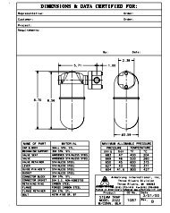
Dimensions and WeightsSound DataSince unit heaters use fans and motors to move air, soundis a natural result. The sound rating of a particular unit maylimit its use in a given application. The following soundrating table is presented to allow you to select a unit basedupon an acceptable sound level.10"–20" UnitsDApproxCFNEBSound DatadBA Sound *Unit Heater Size Pressure Level atVerticalUnit3 Feet from UnitLifting101 63Lugs(Hidden102 63Lines)G121 63122 63141 66142 65161 74162 7324"–48" Units181 77D C182 76Approx.F201 81202 813/4" ø241 82242 82301 84302 83361 85362 85421 841"422 831"G481 85482 85* Per fan. NOTE: Connections are MPTHigh-VelocityNozzleFour-WayDischarge AdapterNS(Sq)High-VelocityNozzleS(Sq)E3"TypABasic LouveredDischargeB3" TypBasic LouveredDischargeA2"(Four-way louver sectionreplaces basic louver section)Heating and Cooling CoilsDimensions and WeightsModelSizeDimensions (in)A B C D E F GConn.MPTBasic Unit With Horizontal orVertical LouversWeights by Core Type (lb)N S ST/AL ST/ST SS/SS10195 105 9515 17-3/4 12 9 1-3/8 4-1/2 4-1/4 1-1/2 10 7102 135 155 145121105 120 11017-1/4 19-3/4 12 9 1-3/8 4-1/2 4-1/4 1-1/2 10-3/4 9-3/4122 150 180 165141120 140 12519-1/2 21-3/4 12 9 1-3/8 4-1/2 4-1/4 1-1/2 11-1/2 11-3/4142 175 210 190161135 165 14522 23-3/4 12 9 1-3/8 4-1/2 4-1/4 1-1/2 12-1/4 14-1/4162 195 240 220181150 185 16024-1/4 25-3/4 12 9 1-3/8 4-1/2 4-1/4 1-1/2 13 16-3/4182 220 280 250<strong>2011</strong>70 210 18026-1/2 27-3/4 12 9 1-3/8 4-1/2 4-1/4 1-1/2 13-3/4 18202 245 315 285241290 350 32032 34-1/4 18 12 2-7/16 6-3/4 4-1/4 2 14-1/2 20-3/4242 360 470 420301360 460 41039-1/4 40-1/4 18 12-1/2 1-13/16 6-3/4 4-1/4 2 18-13/16 26302 460 650 550361440 560 50045-1/4 46-1/4 18 12-1/2 2-5/8 6-1/2 4-1/2 2-1/2 22-7/8 29-1/2362 550 800 680421680 850 77052-1/4 52-1/4 22 15 2-5/8 6-1/4 4-3/4 3 29-3/8 33422 830 1,150 1,010481800 1,030 92059-1/4 58-1/4 22 15 2-3/8 6-1/4 4-3/4 3 31-1/4 38482 990 1,430 1,240* Dual units have twice the width.Additional Weightfor High-VelocityDischarge Nozzle(lb)1114161922241731473547Designs, materials, weights and performance ratings are approximate and subject to change without notice. Visit www.armstronginternational.com for up-to-date information.North America • Latin America • India • Europe / Middle East / Africa • China • Pacific Rimarmstronginternational.com385
Installation GuidelinesBelow are some abbreviated installation guidelines. Consult<strong>Armstrong</strong> for more detailed installation, operation andmaintenance instructions.General Piping Guidelines1. Provide adequate support from the building structure toeliminate piping stresses.2. <strong>All</strong>ow movement of the piping to provide for expansionand contraction. Use swing joints where possible.3. Adequately support all piping. Do not use unit heater forthis purpose.Steam Piping1. Slope steam piping under 10' long toward the steammain. If steam pipe is longer than 10', slope toward theunit and install a drip trap before the unit.2. <strong>All</strong> steam and condensate lines must be of the proper sizeto carry the calculated loads.3. Only continuously draining traps such as invertedbucket or float and thermostatic types should be used.If an inverted bucket trap is used, an air vent should beinstalled downstream of the unit and before the trap.4. Maintain the unit heater outlet size to the trap takeoff.5. If condensate is to be lifted or if the return system ispressurized, use a check valve after the steam trap andprovide a gate valve on the strainer to drain the heater inthe off season.Liquid Piping1. Supply return mains must be sloped for adequate venting.2. Provide air vents at all high points.3. Circulating pumps must be of adequate size to providethe required liquid flow and to overcome the systempressure drops.TTypical Piping ArrangementsAutomaticAir VentHeating and Cooling CoilsHeaterStrainerVacuum BreakerSteam InletSteamMainFloat & ThermostaticSteam TrapReturn MainHeaterRecommended piping arrangement for for steamsteam when draining when draining heater heater to gravity to gravity return. return.Condensate Return LineSupply MainRecommended piping arrangement forfor liquids liquids to to lower lower mains. mains.Return MainSupply MainVacuum BreakerSteamMainSteam InletHeaterAir VentInverted BucketSteam TrapCondensateReturnLineHeaterStrainerDrain ValveRecommended piping arrangement for steamfor when steam draining when draining heater to heater overhead to overhead return. return.Recommended piping arrangement forfor liquids liquids to to overhead mains.386Designs, materials, weights and performance ratings are approximate and subject to change without notice. Visit www.armstronginternational.com for up-to-date information.North America • Latin America • India • Europe / Middle East / Africa • China • Pacific Rimarmstronginternational.com
Sample SpecificationsUnit heaters supplied shall be manufactured with the methods and materials specified as follows:GeneralEnclosures and Louvers—Shall be of minimum 14 gagalvanized steel and finished in gray enamel. (Epoxycoatings and other protective finishes are available.) Fansshall have aluminum alloy blades with steel hubs. (Epoxycoatings and other protective finishes are available.)Motors—Shall be heavy-duty industrial type TEFC, ballbearing, standard NEMA frame motors. Electrical supplyshall be ______ phase ______ volts 60 Hz. (Explosion-proofand other motor types available.)Fan Guards—Shall be provided with each unit and beOSHA approved.Core Type SpecificSteel tube/steel fin:Tubes—Shall be 1" OD 12 ga steel tube. Minimum wallthickness shall be .109".Stainless steel tube/stainless steel fin:Tubes—Shall be 304 L (or 316 L) 1" OD 14 ga stainlesssteel tube. Minimum wall thickness shall be .083".Fins—Shall be helically wound L-footed and of minimum.024" thick steel.Headers—Shall be of carbon steel not less than .145" thick.Connections—Shall be of Schedule 80 carbon steel pipe.Assembly—Shall be welded to form a monometallic,internally wetted surface. Standard testing pressure at 525psig. Pressure parts all welded.Fins—Shall be helically wound L-footed and of minimum.020" thick 304 (or 316) stainless steel.Headers—Shall be of the same stainless steel as the tubesnot less than .109" thick.Connections—Shall be of Schedule 40 stainless steel pipe.Assembly—Shall be welded to form a monometallic,internally wetted surface. Standard testing pressure at 525psig.Heating and Cooling CoilsSteel tube/aluminum fin:Tubes—Shall be of 1" OD 12 ga steel tube. Minimum wallthickness shall be .109".Fins—Shall be helically wound embedded type and ofminimum .020" thick aluminum.Headers—Shall be of carbon steel not less than .145" thick.Connections—Shall be of Schedule 80 carbon steel pipe.Assembly—Shall be welded to form a monometallic,internally wetted surface. Standard testing pressure at 525psig.Stainless steel tube/steel fin:Tubes—Shall be 304 L (or 316 L) 1" OD 14 ga stainlesssteel tube. Minimum wall thickness shall be .083".Fins—Shall be helically wound L-footed and of minimum.024" thick steel.Headers—Shall be of the same stainless steel as the tubesnot less than .109" thick.Connections—Shall be of Schedule 40 stainless steel pipe.Assembly—Shall be welded to form a monometallic,internally wetted surface. Standard testing pressure at 525psig.Designs, materials, weights and performance ratings are approximate and subject to change without notice. Visit www.armstronginternational.com for up-to-date information.North America • Latin America • India • Europe / Middle East / Africa • China • Pacific Rimarmstronginternational.com387