Guide for the Structural Rehabilitation of Heritage ... - Test Input
Guide for the Structural Rehabilitation of Heritage ... - Test Input
Guide for the Structural Rehabilitation of Heritage ... - Test Input

You also want an ePaper? Increase the reach of your titles
YUMPU automatically turns print PDFs into web optimized ePapers that Google loves.
<strong>Guide</strong> <strong>for</strong> <strong>the</strong> <strong>Structural</strong><strong>Rehabilitation</strong> <strong>of</strong> <strong>Heritage</strong> BuildingsCIB Publication 335ISBN: 978-90-6363-066-9
GUIDE FOR THESTRUCTURAL REHABILITATION OF HERITAGE BUILDINGSJune, 2010
GUIDE FOR THESTRUCTURAL REHABILITATION OF HERITAGE BUILDINGSPrepared by CIB CommissionW023 - WALL STRUCTURESEDITING PANELReporterS. Pompeu Santos, PortugalMembersClaudio Modena, ItalyElizabeth Vientzileou, GreeceMiha Tomazevic, SloveniaPaulo Lourenço, PortugalRoberto Capozucca, ItalySamir Chidiac, CanadaWolfram Jaeger, Germany2/48
Thanks are also due to <strong>the</strong> Barry Haseltine, Honorary Commission member, <strong>for</strong> <strong>the</strong> revision<strong>of</strong> <strong>the</strong> English language <strong>of</strong> <strong>the</strong> text.As Coordinator <strong>of</strong> CIB Commission W023-Wall Structures, I hope that this <strong>Guide</strong> will befruitful and will help on structural rehabilitation <strong>of</strong> heritage buildings around <strong>the</strong> world.Lisbon, June, 2010S. Pompeu SantosCIB W023 Commission Coordinator4/48
GUIDE FOR THESTRUCTURAL REHABILITATION OF HERITAGE BUILDINGSTABLE OF CONTENTS1 INTRODUCTION2 GENERAL ASPECTS2.1 The need <strong>for</strong> intervention2.2 Criteria <strong>for</strong> intervention2.3 Methodologies <strong>for</strong> intervention3 THE EXISTING INFORMATION ON THE BUILDING3.1 Documented data about <strong>the</strong> building3.1.1 The historical survey3.1.2 Survey <strong>of</strong> <strong>the</strong> construction <strong>of</strong> <strong>the</strong> building3.2 Survey <strong>of</strong> <strong>the</strong> defects in <strong>the</strong> building3.3 Preliminary assessment3.4 Defects in <strong>the</strong> building3.4.1 General3.4.2 Degradation <strong>of</strong> building materials3.4.3 Damage to building elements3.5 Detailed assessment3.5.1 General3.5.2 In-situ tests3.5.3 Laboratory tests3.5.4 Field tests3.5.5 Assessment <strong>of</strong> <strong>the</strong> foundations3.5.6 Field measurements3.6 Monitoring <strong>of</strong> <strong>the</strong> building3.7 Elaboration <strong>of</strong> <strong>the</strong> diagnosis5/48
4. STRUCTURAL ASSESSMENT OF THE BUILDING4.1 Introduction4.2 Safety level <strong>of</strong> <strong>the</strong> building4.3 Modelling <strong>of</strong> <strong>the</strong> building4.4 Quantification <strong>of</strong> <strong>the</strong> strengths <strong>of</strong> <strong>the</strong> materials4.4.1 Mechanical properties <strong>of</strong> <strong>the</strong> materials4.4.2 Confidence factors4.5 Quantification <strong>of</strong> <strong>the</strong> acting actions4.5.1 General4.5.2 Seismic action4.5.3 Partial factors <strong>for</strong> actions4.6 Safety evaluation5 REPAIR AND STRENGTHENING5.1 The design <strong>of</strong> <strong>the</strong> rehabilitation works5.2 Repair <strong>of</strong> <strong>the</strong> degradation <strong>of</strong> materials5.3 Repair and streng<strong>the</strong>ning <strong>of</strong> <strong>the</strong> structural elements5.4 Upgrading <strong>of</strong> foundations5.5 Improvement <strong>of</strong> safety against earthquakes6 QUALITY OF THE INTERVENTION WORK6.1 Quality control <strong>of</strong> <strong>the</strong> execution <strong>of</strong> <strong>the</strong> work6.3 Qualification <strong>of</strong> <strong>the</strong> intervenersBIBLIOGRAPHY6/48
GUIDE FOR THESTRUCTURAL REHABILITATION OF HERITAGE BUILDINGS1 INTRODUCTION<strong>Heritage</strong> buildings are defined as existing buildings with significant cultural value to society.Developed societies ascribe cultural value to existing buildings, so <strong>the</strong>y are seen as culturalheritage. In general terms, it can be said that <strong>the</strong> cultural value <strong>of</strong> an existing building is ashigh as it is old.<strong>Rehabilitation</strong> <strong>of</strong> heritage buildings has become an issue <strong>of</strong> great importance around <strong>the</strong>world, particularly in <strong>the</strong> most developed societies. It is <strong>the</strong> result <strong>of</strong> <strong>the</strong> need to improveexisting buildings <strong>for</strong> new conditions <strong>of</strong> use, and also <strong>of</strong> <strong>the</strong> recognition <strong>of</strong> <strong>the</strong> importance <strong>of</strong>conservation <strong>of</strong> <strong>the</strong> architectural heritage.Existing buildings are subjected to processes <strong>of</strong> degradation with time, which leads to asituation in which in which <strong>the</strong>y became not able to fulfil <strong>the</strong> purpose <strong>for</strong> which <strong>the</strong>y havebeen built. Sometimes, <strong>the</strong>re is also <strong>the</strong> need to improve <strong>the</strong> conditions <strong>of</strong>fered by <strong>the</strong>existing buildings or to adapt <strong>the</strong>m to new functions.Fur<strong>the</strong>rmore, in <strong>the</strong> most developed societies, as <strong>the</strong>y progress, grows <strong>the</strong> feeling that it isnecessary to maintain <strong>the</strong> existing building heritage. With <strong>the</strong> changes provoked by rapidtechnological evolution, as a kind <strong>of</strong> counterpoint, grows <strong>the</strong> feeling <strong>of</strong> to keep <strong>the</strong> existingbuilt environment and to pass it on to future generations. <strong>Rehabilitation</strong> <strong>of</strong> heritage buildingsis a way <strong>of</strong> sustainable development and also an act <strong>of</strong> culture.The most sensitive aspect <strong>of</strong> <strong>the</strong> rehabilitation <strong>of</strong> existing buildings is <strong>the</strong>ir structuralrehabilitation, i.e., that which is related to <strong>the</strong>ir structural safety. However, <strong>the</strong> assessment <strong>of</strong><strong>the</strong> structural safety <strong>of</strong> existing buildings is, in general, a complex task, because <strong>the</strong>methodologies used differ from those adopted in <strong>the</strong> design <strong>of</strong> new structures. Fur<strong>the</strong>rmore,<strong>the</strong> eventual streng<strong>the</strong>ning <strong>of</strong> existing buildings can conflict with <strong>the</strong>ir cultural value.There<strong>for</strong>e, <strong>the</strong> type <strong>of</strong> intervention on <strong>the</strong> heritage building will depend on <strong>the</strong> existingsituation <strong>of</strong> <strong>the</strong> building, and also, on its cultural value, going from simple maintenance,where <strong>the</strong> objective is not to change <strong>the</strong> cultural value <strong>of</strong> <strong>the</strong> building, to deep rehabilitation,when it is intended to improve <strong>the</strong> per<strong>for</strong>mance <strong>of</strong> <strong>the</strong> building.Being aware <strong>of</strong> <strong>the</strong> importance <strong>of</strong> <strong>the</strong> issue, CIB Commission W023 - Wall Structures hasdecided to develop a document with guidance <strong>for</strong> <strong>the</strong> interventions <strong>of</strong> rehabilitation <strong>of</strong>heritage buildings, with a special emphasis on <strong>the</strong> assessment <strong>of</strong> <strong>the</strong> structural safety,having <strong>the</strong> title: <strong>Guide</strong> <strong>for</strong> <strong>the</strong> <strong>Structural</strong> <strong>Rehabilitation</strong> <strong>of</strong> <strong>Heritage</strong> Buildings.The <strong>Guide</strong> has as its basis <strong>the</strong> CIB Publication <strong>Structural</strong> Assessment and Redesign <strong>of</strong>Masonry Wall Structures, edited in1992, being now <strong>the</strong> focus <strong>for</strong> masonry buildings withsignificant cultural value. It has been developed in line with <strong>the</strong> Publication <strong>of</strong> ICOMOS(ISCARSAH) Recommendations <strong>for</strong> <strong>the</strong> Analysis, Conservation and <strong>Structural</strong> Restoration <strong>of</strong>Architectural <strong>Heritage</strong>, approved in 2003, which philosophy and main concepts have beenadopted.7/48
2 GENERAL ASPECTS2.1 The need <strong>for</strong> interventionAs referred to above, heritage buildings are considered to be existing buildings withsignificant cultural value; <strong>the</strong>y can be buildings, towers, bridges, etc. They are mostly made<strong>of</strong> masonry and timber, sometimes with elements in steel or iron.The need <strong>for</strong> structural rehabilitation <strong>of</strong> heritage buildings is, usually, motivated by one ormore <strong>of</strong> <strong>the</strong> following circumstances:- The existence <strong>of</strong> visible defects in <strong>the</strong> building;- Damage after a particular event that affects its stability (earthquake, etc.);- The change <strong>of</strong> <strong>the</strong> use <strong>of</strong> <strong>the</strong> building <strong>for</strong> most severe conditions; and- Requirement <strong>of</strong> <strong>the</strong> competent authority, <strong>for</strong> instance, when <strong>the</strong>re is an increase in <strong>the</strong>actions (earthquake action, traffic action, etc) imposed by new codes.A basic point in considering structural rehabilitation <strong>of</strong> a heritage building is establishing <strong>the</strong>per<strong>for</strong>mance level to be fulfilled, particularly, <strong>the</strong> requirements in terms <strong>of</strong> structural safety,i.e., <strong>the</strong> structural safety level.When <strong>the</strong>re are no <strong>of</strong>ficial documents, like standards or codes, to be used <strong>for</strong> <strong>the</strong> work, <strong>the</strong>required targets will be established, prior to <strong>the</strong> intervention, by agreement between <strong>the</strong>owner, <strong>the</strong> designer and <strong>the</strong> competent authority.In particular circumstances, <strong>the</strong> per<strong>for</strong>mance level <strong>of</strong> <strong>the</strong> building can still be adjusted during<strong>the</strong> assessment phase, by agreement between those entities.2.2 Criteria <strong>for</strong> intervention<strong>Heritage</strong> buildings, by <strong>the</strong>ir very nature and history (material and assembly), presentchallenges in diagnosis, analysis and rehabilitation, which limits <strong>the</strong> application <strong>of</strong> modernlegal codes and building standards.Fur<strong>the</strong>rmore, <strong>the</strong> structural rehabilitation <strong>of</strong> heritage buildings has implications <strong>of</strong>architectural, structural, economic, historic and social order, depending on <strong>the</strong> degree andextension <strong>of</strong> <strong>the</strong> intervention. All <strong>the</strong>se aspects will be taken into consideration.The intervention <strong>for</strong> structural rehabilitation will involve <strong>the</strong> application <strong>of</strong> technicalknowledge, and also, cultural sensitivity. Only when technique and culture are present, can<strong>the</strong> best decisions about <strong>the</strong> intervention be taken.To succeed well, from <strong>the</strong> technical and <strong>the</strong> cultural points <strong>of</strong> view, intervention will be carriedout on <strong>the</strong> basis <strong>of</strong> principles. The Venice Chart (1964), <strong>for</strong> example, which is one <strong>of</strong> <strong>the</strong>reference documents <strong>for</strong> <strong>the</strong> rehabilitation <strong>of</strong> architectural heritage, defends <strong>the</strong> adoption <strong>of</strong><strong>the</strong> following principles:- Guarantee <strong>of</strong> structural safety;- Respect <strong>for</strong> <strong>the</strong> cultural value <strong>of</strong> <strong>the</strong> building;- Minimum intervention;8/48
- Reversibility <strong>of</strong> <strong>the</strong> intervention;- Integration on <strong>the</strong> whole building;- Compatibility <strong>of</strong> <strong>the</strong> materials;- Minimum cost.It is not always possible to follow all <strong>the</strong>se principles at <strong>the</strong> same time, because, sometimes,<strong>the</strong>y conflict with each o<strong>the</strong>r. For example, <strong>the</strong> achievement <strong>of</strong> structural safety conflicts, very<strong>of</strong>ten, with respect <strong>for</strong> <strong>the</strong> cultural value <strong>of</strong> <strong>the</strong> building. Ano<strong>the</strong>r case is <strong>the</strong> reversibility <strong>of</strong> <strong>the</strong>repair <strong>of</strong> cracks in masonry elements, which to be adequately solved, will not be reversible.In each specific case, compromises between those principles will be necessary, hopefully,subjected to common sense. Maybe, instead <strong>of</strong> principles, it will be more appropriate toconsider <strong>the</strong>m, simply, as references; i.e., reference terms <strong>for</strong> <strong>the</strong> interventions.The Recommendations <strong>of</strong> ICOMOS, referred to above, also contain some Principles, where<strong>the</strong> basic concepts <strong>of</strong> conservation are presented, and <strong>Guide</strong>lines, where <strong>the</strong> rules andmethodology that <strong>the</strong> designer will follow are discussed. Both those Principles and<strong>Guide</strong>lines will also be followed in this <strong>Guide</strong>.2.3 Methodologies <strong>for</strong> interventionThe intervention <strong>for</strong> structural rehabilitation <strong>of</strong> heritage buildings comprises, in general, <strong>the</strong>following phases/actions:- Acquisition <strong>of</strong> documented data about <strong>the</strong> building;- Detailed survey <strong>of</strong> <strong>the</strong> existing condition <strong>of</strong> <strong>the</strong> building;- Elaboration <strong>of</strong> <strong>the</strong> diagnosis (eventually, with <strong>the</strong> carrying <strong>of</strong> tests);- Assessment <strong>of</strong> <strong>the</strong> structural safety;- Design <strong>of</strong> <strong>the</strong> solutions <strong>for</strong> <strong>the</strong> intervention;- Execution <strong>of</strong> <strong>the</strong> intervention.A detailed description <strong>of</strong> <strong>the</strong>se phases/actions will be presented on <strong>the</strong> following sections.Depending on <strong>the</strong> actual conditions <strong>of</strong> <strong>the</strong> building and on <strong>the</strong> objectives to be fulfilled, <strong>the</strong>intervention can assume different <strong>for</strong>ms, going from <strong>the</strong> non invasive (with <strong>the</strong> imposition ornot <strong>of</strong> restrictions <strong>of</strong> use), passing through different kinds <strong>of</strong> works <strong>of</strong> repair and/orstreng<strong>the</strong>ning, until, eventually, partial demolition followed by reconstruction.The decisions about <strong>the</strong> solutions to be adopted on <strong>the</strong> intervention will still be submitted to acost-benefit analysis, in which all <strong>the</strong> relevant aspects will be considered, namely, <strong>the</strong>compatibility <strong>of</strong> <strong>the</strong> structural safety with respect to <strong>the</strong> cultural value <strong>of</strong> <strong>the</strong> building, and <strong>the</strong>cost to be as low as possible.9/48
3 THE EXISTING INFORMATION ON THE BUILDING3.1 Documented data about <strong>the</strong> building3.1.1 The historical surveyAny intervention <strong>for</strong> structural rehabilitation <strong>of</strong> a heritage building needs in<strong>for</strong>mation about itspast, namely, about <strong>the</strong> concept <strong>of</strong> <strong>the</strong> building, as well as about <strong>the</strong> phenomena to which<strong>the</strong> building has been subjected.This historical survey, covering <strong>the</strong> entire life <strong>of</strong> <strong>the</strong> building, aims at understanding <strong>the</strong>concept and <strong>the</strong> purpose <strong>of</strong> <strong>the</strong> building, <strong>the</strong> techniques used in its construction, <strong>the</strong>alterations made to it and its environment, as well as <strong>the</strong> events that could provoke damageto <strong>the</strong> structure, namely, its seismic history.In <strong>the</strong> analysis <strong>of</strong> <strong>the</strong> documents about <strong>the</strong> past <strong>of</strong> <strong>the</strong> building, attention will be given to anyreferences about degradation, reconstruction, additions, structural modifications, etc, or toany o<strong>the</strong>r event that can describe <strong>the</strong> actual situation <strong>of</strong> <strong>the</strong> building.However, attention will also be given to <strong>the</strong> quality <strong>of</strong> <strong>the</strong> documents used. In fact, existingdocuments have, in general, been prepared <strong>for</strong> a purpose different from that <strong>of</strong> structuralengineering, so <strong>the</strong>y can include in<strong>for</strong>mation incorrectly described, or omit important facts orevents that can have influenced <strong>the</strong> structural behaviour <strong>of</strong> <strong>the</strong> building. The sources <strong>of</strong>in<strong>for</strong>mation should be graded according to <strong>the</strong>ir value or <strong>the</strong> confidence that <strong>the</strong>y inspire.Data on <strong>the</strong> past and <strong>the</strong> present modes <strong>of</strong> use or occupancy <strong>of</strong> <strong>the</strong> building are aspects alsoimportant to be verified. The eventual action <strong>of</strong> significant environmental conditions, such as,climatic effects, sudden temperature changes, fire, or any accidental loads (impacts, etc.) willalso be identified.3.1.2 Survey <strong>of</strong> <strong>the</strong> construction <strong>of</strong> <strong>the</strong> buildingThe construction <strong>of</strong> <strong>the</strong> building, including its configuration, <strong>the</strong> types <strong>of</strong> structuralcomponents, and <strong>the</strong> materials used, are aspects that will need considerable attention.This in<strong>for</strong>mation will be obtained from <strong>the</strong> historical archive on <strong>the</strong> building, or from o<strong>the</strong>rsources, such as, reports, drawings, photos, etc, to which it will be possible to have access.It will be complemented with in<strong>for</strong>mation to be obtained during <strong>the</strong> inspections to be carriedout on <strong>the</strong> building, as well as, with interviews with persons familiar with <strong>the</strong> building.Important points on this survey are <strong>the</strong> identification <strong>of</strong> <strong>the</strong> building materials and <strong>of</strong> mainstructural system <strong>of</strong> <strong>the</strong> building, as well as <strong>the</strong> detection <strong>of</strong> irregularities or weak points in<strong>the</strong> building that can have influenced its structural behaviour.3.2 Survey <strong>of</strong> <strong>the</strong> defects in <strong>the</strong> buildingThe survey <strong>of</strong> <strong>the</strong> existing defects in <strong>the</strong> building is usually called preliminary inspection <strong>of</strong><strong>the</strong> building. This survey will be carried out through visual inspection <strong>of</strong> <strong>the</strong> building,eventually, with <strong>the</strong> help <strong>of</strong> simple optical devices (binoculars, etc). In some cases <strong>the</strong>opening up <strong>of</strong> <strong>the</strong> surface <strong>of</strong> elements <strong>of</strong> <strong>the</strong> building, will be required.10/48
In <strong>the</strong> case <strong>of</strong> high-rise buildings, or <strong>of</strong> elements with difficult access, this inspection canrequire <strong>the</strong> installation <strong>of</strong> appropriate means <strong>of</strong> access (scaffolding, cranes, etc.). Theinspection <strong>of</strong> ro<strong>of</strong>s can require particular safety measures.The results <strong>of</strong> <strong>the</strong> preliminary inspection will be given in a report, in which <strong>the</strong> differentmaterials and <strong>the</strong>ir degradations, as well as <strong>the</strong> damage to <strong>the</strong> structural elements, will bepresented.The defects observed will be classified qualitatively, according to <strong>the</strong>ir level <strong>of</strong> importancewith respect to <strong>the</strong> safety <strong>of</strong> <strong>the</strong> building. The defects will be shown on adequate drawings(Fig. 1), or in <strong>the</strong> <strong>for</strong>m <strong>of</strong> check-lists, appropriate to <strong>the</strong> different types <strong>of</strong> structural elements.Figure 1: Mapping <strong>of</strong> <strong>the</strong> defects in a building (13)The registers will be accompanied by detailed photo reports, which can allow <strong>for</strong> <strong>the</strong>relevance <strong>of</strong> details, which, sometimes, miss observation. A video register can also be used,which can allow <strong>for</strong> still more detailed in<strong>for</strong>mation about <strong>the</strong> situation in <strong>the</strong> building.In <strong>the</strong> preliminary inspection it will also be important to verify if <strong>the</strong> atmospheric agents aredegrading <strong>the</strong> building in a particular way. In fact, those effects are <strong>of</strong>ten aggravated ifadequate measures have not been taken during construction (adequate drainage, <strong>for</strong>example), or, if <strong>the</strong>re has not been efficient conservation <strong>of</strong> <strong>the</strong> building.It will still be important to obtain in<strong>for</strong>mation about <strong>the</strong> geotechnical conditions <strong>of</strong> <strong>the</strong> soilsupporting <strong>the</strong> foundations <strong>of</strong> <strong>the</strong> building, namely <strong>the</strong> existence <strong>of</strong> embankments. If <strong>the</strong>re aredegradations in <strong>the</strong> lower part <strong>of</strong> <strong>the</strong> building, it will be convenient to get samples <strong>of</strong> <strong>the</strong> soil,in order to verify if <strong>the</strong>re is contamination by aggressive substances (sulphates, etc.).3.3 Preliminary assessmentAfter <strong>the</strong> preliminary inspection, and taking into account <strong>the</strong> documented in<strong>for</strong>mation, apreliminary assessment <strong>of</strong> <strong>the</strong> situation in <strong>the</strong> building will be carried out. This preliminaryassessment aims to decide about <strong>the</strong> need to continue (or not) <strong>the</strong> investigations and about<strong>the</strong> eventual need <strong>for</strong> urgent measures to be undertaken, related, namely, to <strong>the</strong> continuation<strong>of</strong> <strong>the</strong> use <strong>of</strong> <strong>the</strong> building, or to <strong>the</strong> installation <strong>of</strong> temporary supports.11/48
If <strong>the</strong> available in<strong>for</strong>mation will not be sufficient to elaborate <strong>the</strong> diagnosis <strong>of</strong> <strong>the</strong> situation in<strong>the</strong> building, <strong>the</strong> preliminary assessment should be complemented by a detailed assessment,through <strong>the</strong> carrying out <strong>of</strong> tests and measurements on <strong>the</strong> building (detailed inspection).These measurements can also include <strong>the</strong> geometric survey <strong>of</strong> <strong>the</strong> constitution <strong>of</strong> <strong>the</strong>building, in order to its modelling, as it will be referred later.3.4 Defects in <strong>the</strong> building3.4.1 GeneralThe defects in <strong>the</strong> building can result from <strong>the</strong> degradation <strong>of</strong> <strong>the</strong> building materials or from<strong>the</strong> damage <strong>of</strong> <strong>the</strong> building elements due to mechanical actions.The degradation <strong>of</strong> <strong>the</strong> building materials is a process that develops naturally with time, andcan be accelerated by chemical, physical or biological actions. The main effects are <strong>the</strong>deterioration <strong>of</strong> <strong>the</strong> surfaces <strong>of</strong> <strong>the</strong> elements, <strong>the</strong> loss <strong>of</strong> material and <strong>the</strong> reduction <strong>of</strong> <strong>the</strong>irstrength.The phenomena <strong>of</strong> degradation are different according to <strong>the</strong> type <strong>of</strong> building material:masonry, timber or steel (iron).The damage to <strong>the</strong> building elements due to mechanical actions occurs when <strong>the</strong> actions incertain zones <strong>of</strong> <strong>the</strong> building element exceed <strong>the</strong> strength <strong>of</strong> <strong>the</strong>ir materials. They can beproduced, or be aggravated by actions, or by insufficient strength. Alterations on <strong>the</strong>constitution <strong>of</strong> <strong>the</strong> building can also be <strong>the</strong> source <strong>of</strong> damage <strong>of</strong> this type.The manifestation <strong>of</strong> damage to building elements due to mechanical actions will depend on<strong>the</strong> type <strong>of</strong> action, <strong>the</strong> type <strong>of</strong> building material and <strong>the</strong> type <strong>of</strong> building element.3.4.2 Degradation <strong>of</strong> building materialsa) MasonryThe degradation <strong>of</strong> masonry is linked to <strong>the</strong> characteristics <strong>of</strong> <strong>the</strong> constituent materials:bricks, blocks (<strong>of</strong> stone or concrete), and mortar filling <strong>the</strong> joints. It will be necessary tocorrectly identify <strong>the</strong> materials: <strong>the</strong> stone (limestone, sandstone, etc.), <strong>the</strong> bricks (fired or sundried, etc.), and <strong>the</strong> type <strong>of</strong> mortar (cement, lime, etc.).Masonry is affected by <strong>the</strong> presence <strong>of</strong> water (rain, moisture, etc.), temperature variations(freeze/thaw cycles, etc.) and microclimatic conditions (pollution, etc.), which can provoke itsweakness through <strong>the</strong> development <strong>of</strong> micro-cracks, with <strong>the</strong> consequent loss <strong>of</strong> material,particularly if <strong>the</strong> masonry is not protected by rendering (Fig. 2a). The excessive dryness, aswell as, wind, also can weaken masonry.Degradation <strong>of</strong> masonry due to <strong>the</strong> presence <strong>of</strong> salts (sulphates, nitrates, etc.), in <strong>the</strong> case <strong>of</strong> brickmasonry, and to biological colonisation (moss, etc.) in <strong>the</strong> case <strong>of</strong> stone masonry, can also be verysignificant (Fig. 2b). The excrement <strong>of</strong> birds (pigeons, etc.) is, usually, <strong>the</strong> greatest source <strong>of</strong> <strong>the</strong>setypes <strong>of</strong> problems.A very important problem with masonry is <strong>the</strong> action <strong>of</strong> water resulting from <strong>the</strong> rupture <strong>of</strong>pipes embedded in walls, which can quickly cause damage.12/48
a) Loss <strong>of</strong> material in columns (14) b) Biological colonisation (14)b) TimberFigure 2: Degradations in stone masonryThe main causes <strong>of</strong> <strong>the</strong> degradation <strong>of</strong> timber are <strong>the</strong> attack by fungus and insects. Timberspecies are variably susceptible to degradation and attack, so, a very important issue is <strong>the</strong>correct identification <strong>of</strong> <strong>the</strong> specie <strong>of</strong> <strong>the</strong> timber element.The favourable conditions <strong>for</strong> <strong>the</strong> development <strong>of</strong> fungus in timber are water content higherthan about 20% and high temperatures (25 to 35ºC). The insects xylophages (worms, etc.)develop in drier environments.Timber elements <strong>of</strong> ro<strong>of</strong>s, particularly in <strong>the</strong> vicinity <strong>of</strong> <strong>the</strong>ir supports, are <strong>the</strong> mostsusceptible to fungus attack, due to <strong>the</strong> presence <strong>of</strong> rain water (Fig. 3a). The support zones<strong>of</strong> timber floors on masonry walls are also, <strong>of</strong>ten, a source <strong>of</strong> moisture, due to <strong>the</strong> infiltration<strong>of</strong> water through <strong>the</strong> walls (Fig. 3b).a) In ro<strong>of</strong> elements (21) b) In floor elements (27)Figure 3: Degradations in timber13/48
Attention has also to be given to situations in which <strong>the</strong> timber is integrated in masonry, asare <strong>the</strong> cases <strong>of</strong> walls rein<strong>for</strong>ced with timber trusses or wooden partitions.Particularly delicate are <strong>the</strong> situations in which <strong>the</strong>re are alternate dry/moist conditions, as is<strong>the</strong> case <strong>of</strong> timber piles enclosed in soil having a variable water table; this can lead to <strong>the</strong>quick rotting <strong>of</strong> <strong>the</strong> timber.The presence <strong>of</strong> cracks in timber elements, parallel to <strong>the</strong> fibres, due to <strong>the</strong> shrinkage <strong>of</strong> <strong>the</strong>timber, generally is not a problem, except in <strong>the</strong> case <strong>of</strong> very thick elements, when asignificant reduction <strong>of</strong> <strong>the</strong> shear resistance can occur.c) Steel (iron)The greatest problem with steel and iron elements is corrosion, in particular, <strong>of</strong> <strong>the</strong>connections by rivets or bolts.Ano<strong>the</strong>r important problem to be taken into consideration is <strong>the</strong> eventual corrosion <strong>of</strong> <strong>the</strong>steel elements embedded in masonry elements, which can lead to <strong>the</strong> rupture <strong>of</strong> thoseelements, due to <strong>the</strong> increase <strong>of</strong> volume resulting from <strong>the</strong> rust.It is also to be noted that <strong>the</strong> iron or steel <strong>of</strong> old buildings are, in general, less ductile and lessresistant to fatigue than <strong>the</strong> iron or steel produced nowadays.3.4.3 Damage to building elementsa) Walls and columnsThe relevant actions <strong>for</strong> <strong>the</strong> damage to walls and columns are, in general, <strong>the</strong> vertical loads:self-weights, weights <strong>of</strong> <strong>the</strong> floors, etc. Lateral actions, namely <strong>the</strong> thrust <strong>of</strong> arches and earthpressure, and, particularly, <strong>the</strong> effects <strong>of</strong> earthquakes are also, sometimes, very relevant.In <strong>the</strong> case <strong>of</strong> masonry elements, due to <strong>the</strong>ir low tensile strength, vertical loads can causevertical cracks, which can lead to <strong>the</strong> development <strong>of</strong> lateral de<strong>for</strong>mations and to <strong>the</strong>detachment <strong>of</strong> material. In <strong>the</strong> case <strong>of</strong> composite walls, with two exterior leaves and aninterior in-fill, separation <strong>of</strong> <strong>the</strong> exterior leaves from <strong>the</strong> interior in-fill can also occur.This kind <strong>of</strong> damage can develop slowly (over centuries), or rapidly, but, once <strong>the</strong> processstarts, it can lead to <strong>the</strong> collapse by crushing <strong>of</strong> <strong>the</strong> structural element, even if <strong>the</strong> actions donot increase. The creep <strong>of</strong> masonry (not recognised in <strong>the</strong> past), can aggravate cracking and leadto collapse, even when stresses are moderate.If <strong>the</strong> vertical loads are eccentric <strong>the</strong>y can cause rotation <strong>of</strong> <strong>the</strong> element around <strong>the</strong> base,with <strong>the</strong> development <strong>of</strong> vertical cracks and <strong>the</strong> crushing <strong>of</strong> <strong>the</strong> material on <strong>the</strong> mostcompressed zone. Concentrated loads <strong>of</strong> high magnitude can also lead to <strong>the</strong> localizedcrushing <strong>of</strong> <strong>the</strong> building element.Lateral actions in masonry walls can cause diagonal cracks (Fig. 4) or disruption between elements(Fig. 5), due to <strong>the</strong> low tensile strength <strong>of</strong> <strong>the</strong> units and <strong>of</strong> <strong>the</strong> joints. In masonry columns,lateral actions can also lead to <strong>the</strong>ir loss <strong>of</strong> stability, overturning, or to horizontaldisplacements on <strong>the</strong> joints between blocks (Fig. 6).14/48
) Arches, vaults and domesFigure 4: Damage in walls due to earthquakes (40)In arches, vaults or domes in masonry <strong>the</strong> main source <strong>of</strong> problems is <strong>the</strong> movement at <strong>the</strong>supports, with <strong>the</strong> development <strong>of</strong> tension, and, as a consequence, <strong>the</strong> opening <strong>of</strong> cracks.Such movements are related to <strong>the</strong> occurrence <strong>of</strong> <strong>the</strong> following conditions::Figure 5: Damage in walls due to earth pressure(21)Figure 6: Damage in column due to earthquakes(21)- Deficient conception or execution <strong>of</strong> <strong>the</strong> element: inadequate geometry <strong>for</strong> <strong>the</strong> distribution<strong>of</strong> loads; insufficient resistance or stiffness <strong>of</strong> tie-rods and buttresses; poor quality <strong>of</strong> <strong>the</strong>constituent materials, etc;15/48
- Alteration <strong>of</strong> <strong>the</strong> distribution <strong>of</strong> loads(sometimes, loads are taken <strong>of</strong>f or addedin certain zones <strong>of</strong> <strong>the</strong> element,particularly, fillings);- Actions not <strong>for</strong>eseen: differentialsettlements <strong>of</strong> <strong>the</strong> supports (Fig. 7), etc;- Inadequate maintenance: degradation <strong>of</strong><strong>the</strong> constituent materials, weakness <strong>of</strong> tierodsand buttresses, etc.Masonry vaults supported by steel beamsin building floors are particularly sensitive tolateral movements <strong>of</strong> <strong>the</strong> supports, due to<strong>the</strong>ir, usually, low rise.Figure 7: Cracks in a masonry vault (24)c) Towers and chimneysThese types <strong>of</strong> elements are characterizedby being, in general, subjected to highcompression stresses in <strong>the</strong> bottom zone,which can lead to <strong>the</strong> development <strong>of</strong>vertical cracks, as referred to <strong>for</strong> walls (Fig.8).They are particularly sensitive to movements<strong>of</strong> <strong>the</strong> foundations and to alterations, namelyto <strong>the</strong> introduction <strong>of</strong> openings. Prismaticelements can also be weakened byimperfect connections between walls.d) Framed elementsThe main problems encountered with framedelements <strong>of</strong> timber or steel, used as <strong>the</strong>structure <strong>of</strong> <strong>the</strong> ro<strong>of</strong>s or floors <strong>of</strong> buildings,are <strong>the</strong> de<strong>for</strong>mation <strong>of</strong> <strong>the</strong> elements or <strong>of</strong> <strong>the</strong>joints, due to excessive loads or to actionsnot took into account in <strong>the</strong> design, such asearthquakes, <strong>for</strong> example.Figure 8: Vertical cracking in a masonry chimney(21)3.5 Detailed assessment3.5.1 GeneralAs referred to above, when <strong>the</strong> available in<strong>for</strong>mation is not sufficient to elaborate <strong>the</strong>diagnosis <strong>of</strong> <strong>the</strong> situation in <strong>the</strong> building, <strong>the</strong> preliminary assessment will be complementedby a detailed assessment <strong>of</strong> <strong>the</strong> building. This detailed assessment will include a detailedinspection, which can comprise in-situ tests, laboratory tests, field tests, assessment <strong>of</strong> <strong>the</strong>foundations and also field measurements.16/48
As tests are, in general, very expensive, and carrying <strong>the</strong>m out can affect <strong>the</strong> cultural value<strong>of</strong> <strong>the</strong> building, <strong>the</strong> number and <strong>the</strong> place in which <strong>the</strong>y are planned to be per<strong>for</strong>med shouldbe considered sensitively. As a rule, <strong>the</strong> tests to be carried out will be based on a clear vision<strong>of</strong> <strong>the</strong> phenomena <strong>for</strong> which characterization or understanding is relevant.In <strong>the</strong> planning <strong>of</strong> <strong>the</strong> program <strong>of</strong> tests, two phases will, in general, be considered: <strong>the</strong> firstone, in which <strong>the</strong> aim is <strong>the</strong> acquisition <strong>of</strong> <strong>the</strong> primary in<strong>for</strong>mation; and <strong>the</strong> second one, inwhich <strong>the</strong> aim is to refine <strong>the</strong> in<strong>for</strong>mation obtained during <strong>the</strong> first phase, carrying out anadditional number <strong>of</strong> tests or more specific tests.After carrying out <strong>the</strong> tests, <strong>the</strong> results obtained will be carefully analysed. In particularsituations, alternate methods <strong>of</strong> tests will be used, and <strong>the</strong>ir results compared, <strong>for</strong> calibration.The tests can be non-destructive (or slightly intrusive), when <strong>the</strong>y have a negligible influenceon <strong>the</strong> building, or destructive (in any way), o<strong>the</strong>rwise.Non-destructive tests (“NDT”) are, obviously, <strong>the</strong> preferable ones <strong>for</strong> heritage buildings. Ifnon-destructive tests will not be sufficient, destructive tests will be considered, but <strong>the</strong>y willbe carried out only after a cost-benefit analysis.In this analysis, <strong>the</strong> global cost will be <strong>the</strong> cost <strong>of</strong> <strong>the</strong> tests plus <strong>the</strong> eventual loss on <strong>the</strong>cultural value <strong>of</strong> <strong>the</strong> building due to <strong>the</strong> carrying <strong>of</strong> <strong>the</strong> tests, and <strong>the</strong> benefit will be <strong>the</strong>eventual reduction on <strong>the</strong> size <strong>of</strong> <strong>the</strong> intervention due to <strong>the</strong> improvement in <strong>the</strong> quality <strong>of</strong> <strong>the</strong>in<strong>for</strong>mation.3.5.2 In-situ testsIn <strong>the</strong> case <strong>of</strong> masonry elements, <strong>the</strong> available most common non-destructive techniques <strong>for</strong>in-situ tests are ultra-sonic tests and analysis with endoscope; flat jack tests are also veryuseful, but <strong>the</strong>y are slightly destructive.The ultra-sonic device measures <strong>the</strong> speed <strong>of</strong> a sonic pulse through <strong>the</strong> masonry element. Itallows <strong>for</strong> in<strong>for</strong>mation to be obtained about <strong>the</strong> stiffness and <strong>the</strong> resistance <strong>of</strong> <strong>the</strong> masonry,but in a qualitative way, only. It also allows <strong>for</strong> in<strong>for</strong>mation about <strong>the</strong> presence <strong>of</strong> voids oro<strong>the</strong>r discontinuities. It is completely non-destructive.The endoscope (fibre optic viewing device) allows <strong>the</strong> observation <strong>of</strong> <strong>the</strong> interior <strong>of</strong> masonryelements and <strong>the</strong> conditions <strong>of</strong> <strong>the</strong> materials around holes drilled in those elements. It is veryeffective, causing minor damage <strong>for</strong> a moderate cost.The flat jack technique consists <strong>of</strong> <strong>the</strong> <strong>for</strong>mation <strong>of</strong> small slots in <strong>the</strong> masonry, in which flatjacks <strong>of</strong> small depth are introduced (Fig. 9).By measuring <strong>the</strong> applied pressures, as well as <strong>the</strong> de<strong>for</strong>mations between <strong>the</strong> slots, thistechnique allows <strong>the</strong> measurement <strong>of</strong> <strong>the</strong> stress-strain relationships <strong>of</strong> <strong>the</strong> masonry between<strong>the</strong> slots, and so <strong>the</strong> obtaining <strong>of</strong> its modulus <strong>of</strong> elasticity.17/48
Increasing <strong>the</strong> applied loads, thistechnique can also enable <strong>the</strong>resistance <strong>of</strong> <strong>the</strong> masonry, incompression, to be obtained, but, in thatcase, it becomes partially destructive.Jacks need to be calibrated individually.In <strong>the</strong> case <strong>of</strong> thick walls, instead <strong>of</strong> flatjacks, one can use <strong>the</strong> dilatometer,(whose principle <strong>of</strong> functioning isidentical to that <strong>of</strong> flat jacks), which isintroduced along holes made through<strong>the</strong> walls (as in <strong>the</strong> case <strong>of</strong> <strong>the</strong>endoscope).Figure 9: <strong>Test</strong>s with flat jacks in masonry walls (2)O<strong>the</strong>r techniques, also useful, are <strong>the</strong>drilling energy test and radar.The drilling energy test, whichmeasures <strong>the</strong> power consumption <strong>for</strong> drilling a standard diameter hole in masonry elements,has been used to assess <strong>the</strong>ir compressive strength. However, test results have to becalibrated by comparison with o<strong>the</strong>r means.Radar measures <strong>the</strong> time <strong>of</strong> flight <strong>of</strong> radar pulses between <strong>the</strong> surface and reflecting featuresinside <strong>the</strong> masonry. It allows <strong>for</strong> <strong>the</strong> detection <strong>of</strong> ties inside <strong>the</strong> masonry, and also <strong>for</strong>measurement <strong>of</strong> thicknesses in masonry elements. It is also useful to detect zones withmoisture, voids, or o<strong>the</strong>r discontinuities, as an alternative to ultra-sonic tests. It is completelynon-destructive.In <strong>the</strong> case <strong>of</strong> timber elements, in-situ non-destructive tests are also available, such as, <strong>the</strong>use <strong>of</strong> <strong>the</strong> metallic blade and <strong>the</strong> impact hammer. They are not very reliable, yet, so <strong>the</strong>y willnot be used in isolation.In <strong>the</strong> case <strong>of</strong> steel elements, <strong>the</strong> most common in-situ test is <strong>the</strong> impact hammer, which canallow in<strong>for</strong>mation to be obtained about <strong>the</strong> extension and <strong>the</strong> depth <strong>of</strong> corrosion.3.5.3 Laboratory testsThe assessment <strong>of</strong> <strong>the</strong> characteristics <strong>of</strong> building materials is usually carried out takingsamples from some <strong>of</strong> <strong>the</strong> structural elements: cores, in <strong>the</strong> case <strong>of</strong> masonry elements, andsmall fragments, in <strong>the</strong> case <strong>of</strong> timber or steel elements, and carrying out laboratory tests onspecimens made from those samples.The laboratory tests can be mechanical tests: <strong>of</strong> compression, tensile or <strong>of</strong> shear strength,etc. (Figs. 10a and 10b); chemical tests: chemical composition, etc.; or mineralogical tests:mineralogical composition, etc.18/48
a) Masonry core (21) b) Steel specimens (21)Figure 10: Specimens <strong>for</strong> material testingThe taking <strong>of</strong> samples from <strong>the</strong> building will be carefully specified as to <strong>the</strong>ir number and<strong>the</strong>ir location in <strong>the</strong> building, in order that <strong>the</strong> in<strong>for</strong>mation obtained has <strong>the</strong> required qualityand that <strong>the</strong> cultural value <strong>of</strong> <strong>the</strong> building will not be significantly affected. It will be verifiedthat <strong>the</strong> taking <strong>of</strong> <strong>the</strong> samples will not compromise <strong>the</strong> existing structural safety <strong>of</strong> <strong>the</strong>building, particularly, in <strong>the</strong> case <strong>of</strong> steel or timber elements.In <strong>the</strong> case <strong>of</strong> very thick masonry walls,attention will be given to <strong>the</strong> fact that <strong>the</strong>ycan be very heterogeneous, having, ingeneral two exterior leaves <strong>of</strong> good quality,and an interior core, generally, <strong>of</strong> rubble <strong>of</strong>bad quality. To take into account thisheterogeneity, large samples (prisms) haveto be taken from <strong>the</strong> site and tested afteradequate preparation in <strong>the</strong> laboratory (Fig.11). As this solution is very much intrusiveand expensive, it can only be adopted inparticular circumstances, <strong>for</strong> example, whendemolition is to be carried out.Sometimes, even complete walls are takenfrom <strong>the</strong> site and tested in a laboratory,Figure 11: Specimen <strong>of</strong> masonry wall <strong>for</strong> a shear allowing <strong>for</strong> obtaining, with great accuracy,test in laboratory (21)<strong>the</strong> mechanical characteristics <strong>of</strong> masonry incompression and in shear, as well as <strong>the</strong>evaluation <strong>of</strong> <strong>the</strong> seismic behaviour <strong>of</strong> <strong>the</strong> building (Fig. 12).When it is not possible to take samples from <strong>the</strong> masonry in <strong>the</strong> building, one alternativesolution consists in building specimens in a laboratory, using units and mortar identical to <strong>the</strong>original ones. Apart from <strong>the</strong> difficulty in building specimens that simulate <strong>the</strong> real walls thissolution has <strong>the</strong> advantage <strong>of</strong> enabling <strong>the</strong>m to be made in great numbers, allowing also <strong>for</strong><strong>the</strong> simulation <strong>of</strong> <strong>the</strong> variation <strong>of</strong> several parameters.19/48
a) <strong>Test</strong> set-up b) The wall after testedFigure 12: Laboratory test <strong>of</strong> a timber framed infill wall under cyclic alternated actions (5)Instead <strong>of</strong> macro-specimens, it is also possible to carry out tests in a laboratory using microspecimens(Figs. 13), taking into account <strong>the</strong> scale effect, when relevant (Fig.14).a) Triplet test b) Shear testFigure 13: Apparatus <strong>for</strong> shear tests on masonry specimens at 1/3 scale (40)It is to be noted that <strong>the</strong> empirical models adopted in modern codes, which use relationshipsbetween <strong>the</strong> compressive strength <strong>of</strong> <strong>the</strong> masonry, <strong>the</strong> masonry units and <strong>of</strong> <strong>the</strong> mortar, are,in general, not applicable to old masonry.3.5.4 Field testsCharacterisation <strong>of</strong> <strong>the</strong> strength <strong>of</strong> <strong>the</strong> masonry in compression or in shear is sometimescarried out, using testing devices appropriate to <strong>the</strong> field conditions (Fig. 15). Since <strong>the</strong>se testsbecome very intrusive to <strong>the</strong> building, <strong>the</strong>y are only possible in very particular situations.20/48
Figure 14: Shaking-table test <strong>of</strong> a masonrybuilding at 2/3 scale (41)Figure 15: In-situ test <strong>of</strong> <strong>the</strong> lateral resistance <strong>of</strong> amasonry wall (26)To characterize <strong>the</strong> dynamic behaviour <strong>of</strong> <strong>the</strong> building, dynamic tests are <strong>of</strong>ten used,allowing <strong>for</strong> obtaining <strong>the</strong> fundamental frequencies, damping, etc., which will be very useful,particularly in <strong>the</strong> cases <strong>of</strong> complex masonry buildings. The comparison <strong>of</strong> <strong>the</strong> resultsobtained on <strong>the</strong>se measurements with those obtained from <strong>the</strong> modelling <strong>of</strong> <strong>the</strong> building, willbe very helpful <strong>for</strong> <strong>the</strong> refinement <strong>of</strong> <strong>the</strong> structural model <strong>of</strong> <strong>the</strong> building.3.5.5 Assessment <strong>of</strong> <strong>the</strong> foundationsThe knowledge about <strong>the</strong> existingfoundations <strong>of</strong> <strong>the</strong> building will be <strong>of</strong>primary importance. Besides <strong>the</strong>geotechnical characterisation, it will also benecessary to conduct research to allow <strong>for</strong><strong>the</strong> definition <strong>of</strong> <strong>the</strong> geometry <strong>of</strong> <strong>the</strong>foundation elements.The assessment <strong>of</strong> <strong>the</strong> conditions <strong>of</strong> <strong>the</strong>foundations is usually made through <strong>the</strong>execution <strong>of</strong> shafts in particular zones <strong>of</strong><strong>the</strong> building (Fig. 16).In this assessment attention will be given to<strong>the</strong> characteristics <strong>of</strong> <strong>the</strong> soil and to <strong>the</strong>water table, as well as to <strong>the</strong> presence <strong>of</strong>substances that can attack <strong>the</strong> building bycapillary action (chlorides, nitrates, etc.).Figure16: Shaft <strong>for</strong> <strong>the</strong> geotechnical recognition <strong>of</strong>building foundations (21)21/48
Particular attention will also be given to check <strong>the</strong> existence <strong>of</strong> embankments and to <strong>the</strong>identification <strong>of</strong> <strong>the</strong> drainage system <strong>of</strong> <strong>the</strong> building.The adequate characterisation <strong>of</strong> <strong>the</strong> foundation soil sometimes needs undisturbed samples tobe taken and tested in <strong>the</strong> laboratory. Penetrometer tests are also <strong>of</strong> great value, allowing <strong>for</strong> <strong>the</strong>stratification to be assessed and <strong>for</strong> a reduction in <strong>the</strong> number <strong>of</strong> samples needed.3.5.6 Field measurementsThe detailed assessment <strong>of</strong> a building can also include <strong>the</strong> measurement <strong>of</strong> de<strong>for</strong>mations instructural elements <strong>of</strong> <strong>the</strong> building, such as <strong>the</strong> inclination <strong>of</strong> columns and <strong>the</strong> lateralde<strong>for</strong>mation <strong>of</strong> walls. Sometimes, it includes, simply, <strong>the</strong> measurement <strong>of</strong> <strong>the</strong> width <strong>of</strong> cracksin building elements (Fig.17).It can still include <strong>the</strong> detailed survey <strong>of</strong><strong>the</strong> geometry <strong>of</strong> <strong>the</strong> building, in order toallow <strong>for</strong> its modelling, so as to support<strong>the</strong> diagnosis, and <strong>for</strong> <strong>the</strong> structuralassessment <strong>of</strong> <strong>the</strong> building.The measurement <strong>of</strong> de<strong>for</strong>mations instructural elements <strong>of</strong> <strong>the</strong> building usuallyuses topographic techniques, such asprecision levelling, etc.In <strong>the</strong> measuring <strong>of</strong> <strong>the</strong> dimensions <strong>of</strong> <strong>the</strong>building elements, <strong>the</strong> topographictechniques are also used, in addition to<strong>the</strong> common means <strong>of</strong> measuringdimensions in <strong>the</strong> field. Usually,advantage is taken <strong>of</strong> <strong>the</strong> installation <strong>of</strong>any special means used <strong>for</strong> <strong>the</strong> visualinspection, to carry out this survey.Figure 17: Ruler measuring <strong>the</strong> width <strong>of</strong> cracks in walls(21)For <strong>the</strong> measurement <strong>of</strong> <strong>the</strong> thickness <strong>of</strong> <strong>the</strong> elements a method commonly used is radar.However, as this technique is not very accurate, it has to be complemented by o<strong>the</strong>r means,<strong>for</strong> example, with <strong>the</strong> drilling <strong>of</strong> small holes through some elements, <strong>for</strong> calibration.In <strong>the</strong> case <strong>of</strong> monuments or o<strong>the</strong>r complex structures, <strong>the</strong> photogrammetric technique canalso be very useful <strong>for</strong> <strong>the</strong> survey <strong>of</strong> <strong>the</strong> geometry <strong>of</strong> <strong>the</strong> building, as well as <strong>for</strong> <strong>the</strong> register <strong>of</strong><strong>the</strong> defects in <strong>the</strong> building (Fig. 18a).More recently, <strong>the</strong> “laser” sweeping technique has appeared, which allows <strong>for</strong> <strong>the</strong> obtaining<strong>of</strong> a “cloud” <strong>of</strong> coordinated points in “3D”, from which it is even possible to construct anumerical model <strong>of</strong> <strong>the</strong> building (Fig. 18b).22/48
a) Photogrammetric survey (16) b) Laser sweeping survey (21)Figure18: Survey <strong>of</strong> <strong>the</strong> geometry <strong>of</strong> <strong>the</strong> building3.6 Monitoring <strong>of</strong> <strong>the</strong> buildingThe monitoring <strong>of</strong> <strong>the</strong> building during a certain period <strong>of</strong> time can be an adequate measure to help<strong>the</strong> elaboration <strong>of</strong> <strong>the</strong> diagnosis, particularly when <strong>the</strong>re may be non-stabilized phenomena,allowing <strong>for</strong> showing its evolution.The monitoring <strong>of</strong> <strong>the</strong> building consists in <strong>the</strong> measurement <strong>of</strong> parameters, such as,de<strong>for</strong>mations, movements <strong>of</strong> cracks, levels, temperature variations, etc., in strategic points <strong>of</strong><strong>the</strong> building, at certain moments, during a certain period <strong>of</strong> time.The monitoring techniques can range from <strong>the</strong> simple placing <strong>of</strong> gypsum ‘tell-tales’ (Fig. 19a)or crackmeters on cracks, to a modern monitoring systems using sensors: electricextensometers, displacement transducers, <strong>the</strong>rmometers, accelerometers, etc. (Fig. 19b),connected to a data acquisition device, which can acquire data at pre-defined intervals <strong>of</strong> time.The photogrammetric technique can also be used as a method <strong>of</strong> monitoring.The monitoring <strong>of</strong> <strong>the</strong> building can also be done during <strong>the</strong> rehabilitation phase, in which <strong>the</strong>data that is being obtained is used as a basis <strong>for</strong> subsequent decisions, allowing, sometimes,<strong>for</strong> <strong>the</strong> reduction <strong>of</strong> <strong>the</strong> size <strong>of</strong> <strong>the</strong> intervention. Continuing monitoring <strong>of</strong> <strong>the</strong> building can also beuseful after <strong>the</strong> rehabilitation works, or when doubts still remain about <strong>the</strong> need <strong>for</strong> more measures<strong>of</strong> intervention (long-term monitoring).By comparing <strong>of</strong> <strong>the</strong> results obtained from <strong>the</strong> monitoring <strong>of</strong> <strong>the</strong> building with <strong>the</strong> resultsobtained from its modelling, it will be also possible to refine <strong>the</strong> modelling (see section 4).Monitoring systems permit <strong>the</strong> storage <strong>of</strong> <strong>the</strong> acquired data and its transmission via landlines or through <strong>the</strong> internet. They can also function as an alarm, which can be very useful insome situations.23/48
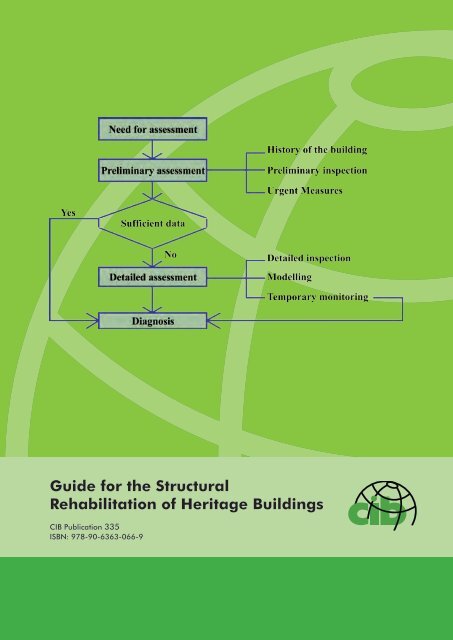
a) With gypsum ‘tell-tales’ (21) b) With displacement transducers (3)Figure 19: Monitoring <strong>of</strong> cracks in buildingsBecause <strong>the</strong> installation <strong>of</strong> a monitoring system in <strong>the</strong> building is, in general, very expensive,it should be <strong>the</strong> object <strong>of</strong> a cost-benefit analysis and only <strong>the</strong> in<strong>for</strong>mation relevant to <strong>the</strong>evolution <strong>of</strong> <strong>the</strong> phenomena will be registered. The subsequent treatment <strong>of</strong> <strong>the</strong> in<strong>for</strong>mationthat is being acquired should also be assured.3.7 Elaboration <strong>of</strong> <strong>the</strong> diagnosisThe diagnosis <strong>of</strong> <strong>the</strong> situation in <strong>the</strong> building is <strong>the</strong> process <strong>of</strong> identifying or determining <strong>the</strong>nature and <strong>the</strong> cause <strong>of</strong> <strong>the</strong> defects in <strong>the</strong> building.The diagnosis is a very delicate task, because <strong>the</strong> available data refers to <strong>the</strong> effects(symptoms), while <strong>the</strong> causes that are <strong>the</strong>ir origin (or, as it usually happens, <strong>the</strong> severalconcomitant causes) are what need to be identified. Intuition and experience are essentialcomponents <strong>of</strong> <strong>the</strong> diagnosis.On figure 20 a flowchart <strong>of</strong> <strong>the</strong> actions to be undertaken in <strong>the</strong> elaboration <strong>of</strong> <strong>the</strong> diagnosis ispresented.For <strong>the</strong> elaboration <strong>of</strong> <strong>the</strong> diagnosis, an interpretative model (scenario) that interprets <strong>the</strong>existing defects in <strong>the</strong> building will be established, based on <strong>the</strong> results <strong>of</strong> preliminaryinspection. When that in<strong>for</strong>mation is not sufficient, it has to be complemented by a detailedinspection, and, eventually, by <strong>the</strong> modelling <strong>of</strong> <strong>the</strong> building.On this modelling, usually, simplified models are used, but, in some circumstances,sophisticated models may be needed (see, section 4). The properties <strong>of</strong> <strong>the</strong> building materialsand <strong>the</strong> values <strong>of</strong> <strong>the</strong> actions to be adopted on this modelling will be <strong>the</strong> nominal ones,obtained directly from <strong>the</strong> tests or from <strong>the</strong> field measurements, without using any safetycoefficients).24/48
Figure 20: Flowchart <strong>of</strong> <strong>the</strong> actions to be undertaken <strong>for</strong> <strong>the</strong> diagnosis <strong>of</strong> <strong>the</strong> building (38)These sources <strong>of</strong> in<strong>for</strong>mation will confirm (or not) <strong>the</strong> interpretative model (scenario) that hasbeen advanced. In <strong>the</strong> last case, an alternate scenario will be established and, eventually,confirmed.If <strong>the</strong> situation does not become completely clear, <strong>the</strong> best solution will be to keep <strong>the</strong>building under observation (monitoring) <strong>for</strong> a certain period <strong>of</strong> time, which will allow <strong>for</strong> <strong>the</strong>evolution <strong>of</strong> <strong>the</strong> phenomena and, subsequently, <strong>for</strong> a better understanding <strong>of</strong> what is, in fact,happening to <strong>the</strong> building.25/48
4 STRUCTURAL ASSESSMENT OF THE BUILDING4.1 IntroductionThe structural assessment <strong>of</strong> heritage buildings is <strong>the</strong> evaluation <strong>of</strong> <strong>the</strong> collected data relatedto <strong>the</strong> safety <strong>of</strong> <strong>the</strong> building, with <strong>the</strong> objective <strong>of</strong> deciding whe<strong>the</strong>r its structural safety issufficient, or not. It is an essential phase <strong>of</strong> an intervention <strong>of</strong> rehabilitation, because it iswhen it is decided if measures are necessary and to what extent.The structural assessment <strong>of</strong> <strong>the</strong> building is usually based on <strong>the</strong> modelling <strong>of</strong> its structuralbehaviour, in which, as <strong>for</strong> new buildings, through certain hypo<strong>the</strong>ses, <strong>the</strong> effects <strong>of</strong> <strong>the</strong>actions on <strong>the</strong> building are determined and combined, being <strong>the</strong> results compared with <strong>the</strong>strength <strong>of</strong> <strong>the</strong> building (or in strategic points <strong>of</strong> <strong>the</strong> building).However, due to <strong>the</strong> specifics <strong>of</strong> heritage buildings <strong>the</strong>re are substantial differences in <strong>the</strong>procedures to be used on both <strong>the</strong> structural modelling and on <strong>the</strong> safety verification, incomparison with new buildings.Concerning <strong>the</strong> modelling <strong>of</strong> <strong>the</strong> building, it is to be noted that, owing to <strong>the</strong> simplificationsthat are, in general, necessarily adopted, and to <strong>the</strong> possible lack <strong>of</strong> knowledge about <strong>the</strong>events to which <strong>the</strong> building has been subjected in <strong>the</strong> past, <strong>the</strong> results obtained are, ingeneral, less reliable than would be <strong>the</strong> case <strong>for</strong> <strong>the</strong> design <strong>of</strong> new buildings.Concerning <strong>the</strong> safety verification, specific issues also arise. In modern codes, <strong>the</strong>uncertainties, both on <strong>the</strong> side <strong>of</strong> <strong>the</strong> strength <strong>of</strong> materials and on <strong>the</strong> side <strong>of</strong> <strong>the</strong> actions, aretaken into account through <strong>the</strong> application <strong>of</strong> successive safety coefficients, which lead inpractice, to a high safety level on <strong>the</strong> buildings.This approach is, generally, well accepted by society, because <strong>the</strong> increase in safety doesnot result in a significant increase <strong>of</strong> cost. In <strong>the</strong> case <strong>of</strong> heritage buildings this approachwould be inappropriate, because it could require very intrusive and costly rehabilitationworks, which, sometimes, are not justified. Fur<strong>the</strong>rmore, as <strong>the</strong> properties <strong>of</strong> <strong>the</strong> buildingmaterials naturally decrease with time, safety levels lower than those in new buildings wouldbe acceptable <strong>for</strong> existing buildings.It is also to be noted that <strong>the</strong> safety coefficients prescribed in <strong>the</strong> design <strong>of</strong> new buildingstake into account uncertainties related to <strong>the</strong> building process, which, in <strong>the</strong> case <strong>of</strong> existingbuildings do not exist, because <strong>the</strong>ir behaviour can be observed. The possible reduction <strong>of</strong><strong>the</strong>se coefficients does not mean, necessarily, that <strong>the</strong> safety <strong>of</strong> <strong>the</strong> building is notacceptable.4.2 Safety level <strong>of</strong> <strong>the</strong> buildingIn establishing <strong>the</strong> required safety level <strong>of</strong> heritage buildings, a holistic and flexible approachshould be adopted, in a way that, to guarantee <strong>the</strong>ir safety, <strong>the</strong> streng<strong>the</strong>ning measures to becarried out will be reduced as much as possible, and <strong>the</strong> loss <strong>of</strong> <strong>the</strong> cultural value <strong>of</strong> <strong>the</strong>building will be minimized.Thus, in heritage buildings, safety levels lower than those prescribed <strong>for</strong> new buildings will beacceptable, since it will be possible to take measures in order to reduce <strong>the</strong> risk associated withdiminishing <strong>the</strong> safety level, <strong>for</strong> example, by adopting restrictions on <strong>the</strong> use <strong>of</strong> <strong>the</strong> building.26/48
Fur<strong>the</strong>rmore, in <strong>the</strong> case that safety levels identical to those prescribed <strong>for</strong> new buildings areadopted, partial factors <strong>for</strong> both <strong>the</strong> strength <strong>of</strong> <strong>the</strong> materials and <strong>the</strong> values <strong>of</strong> <strong>the</strong> actions,lower than those prescribed <strong>for</strong> new buildings, can still be used if <strong>the</strong> assumed reduction <strong>of</strong><strong>the</strong> uncertainties associated with <strong>the</strong>se variables is taken into account.The establishment <strong>of</strong> <strong>the</strong> safety level <strong>of</strong> a heritage building should, in particular cases, besubjected to a cost-benefit analysis, being <strong>the</strong> benefit <strong>the</strong> reduction <strong>of</strong> <strong>the</strong> risk, and <strong>the</strong> costbeing <strong>the</strong> possible reduction <strong>of</strong> <strong>the</strong> cultural value <strong>of</strong> <strong>the</strong> building resulting from <strong>the</strong>intervention <strong>of</strong> rehabilitation, in addition to <strong>the</strong> cost <strong>of</strong> <strong>the</strong> intervention itself.As referred to above, in <strong>the</strong> case <strong>of</strong> buildings with high cultural value <strong>the</strong> safety level to beadopted should always be agreed between <strong>the</strong> designer, <strong>the</strong> owner and <strong>the</strong> competentauthority.4.3 Modelling <strong>of</strong> <strong>the</strong> buildingThe structural model (or models) <strong>of</strong> <strong>the</strong> building are <strong>the</strong> set <strong>of</strong> structural elements(components) used to represent <strong>the</strong> structural functioning <strong>of</strong> <strong>the</strong> building. The model shouldadequately represent <strong>the</strong> structural behaviour <strong>of</strong> <strong>the</strong> building and <strong>the</strong> phenomena which arerelated to it, using calculation methods that are readily available, as much as possible.The process <strong>of</strong> modelling <strong>of</strong> heritage buildings is similar to that <strong>for</strong> new buildings, in which,in<strong>for</strong>mation about <strong>the</strong> existing stresses (or ones that can be produced) in <strong>the</strong> variousstructural elements <strong>of</strong> <strong>the</strong> building are calculated.As referred to above, <strong>the</strong> modelling <strong>of</strong> heritage buildings is, in general, more difficult and lessreliable than in <strong>the</strong> case <strong>of</strong> new buildings. This is due to several factors, such as:- The difficulty in adequately modelling its structure;- The uncertainties related to <strong>the</strong> characteristics <strong>of</strong> <strong>the</strong> constituent materials in <strong>the</strong> wholebuilding;- The influence <strong>of</strong> past phenomena or events (not always obvious), as well as, <strong>the</strong> imperfectknowledge about alterations or repairs made in <strong>the</strong> past.Apart from <strong>the</strong> lower reliability, <strong>the</strong> data obtained from <strong>the</strong> modelling <strong>of</strong> heritage buildings willbe always useful, giving, at least, trends, such as <strong>the</strong> direction and order <strong>of</strong> magnitude <strong>of</strong> <strong>the</strong>stresses, possible critical zones, etc. The modelling will also be helpful in <strong>the</strong> design <strong>of</strong> <strong>the</strong>eventual streng<strong>the</strong>ning, by comparing <strong>the</strong> results obtained with <strong>the</strong> modelling <strong>of</strong> <strong>the</strong> existingbuilding with <strong>the</strong> results obtained <strong>for</strong> <strong>the</strong> same building on which <strong>the</strong> streng<strong>the</strong>ning measuresthat are being planned, are included.For <strong>the</strong> modelling <strong>of</strong> heritage buildings, models with different levels <strong>of</strong> sophistication can beused, depending on <strong>the</strong> specific situation.In some situations, and <strong>for</strong> a preliminary evaluation, simplified models, based on simplestatic conditions <strong>of</strong> equilibrium, manual calculations or graphical methods (Fig. 21) can beuseful.However, nowadays, <strong>the</strong> most common modelling methods are <strong>the</strong> numerical ones, usingmeshes <strong>of</strong> finite elements, appropriate <strong>for</strong> <strong>the</strong> representation <strong>of</strong> <strong>the</strong> behaviour <strong>of</strong> <strong>the</strong>structural elements <strong>of</strong> <strong>the</strong> building.27/48
There are several computational s<strong>of</strong>tware methods,commercially available <strong>for</strong> <strong>the</strong> modelling <strong>of</strong> heritagebuildings, both static and dynamic, with variedsophistication.For common buildings, <strong>the</strong> simple planar (or threedimensional)multi degree <strong>of</strong> freedom shear systems arecurrently used. For buildings such as monuments,churches, etc, it will be more appropriate to use s<strong>of</strong>twarewith finite continuum elements (Figs. 22 and 23).It is to be noted that <strong>the</strong> analysis through complex modelsis, in general, expensive, because <strong>of</strong> <strong>the</strong> preparation <strong>of</strong><strong>the</strong> input data and <strong>of</strong> <strong>the</strong> consideration <strong>of</strong> <strong>the</strong> quantity <strong>of</strong>results obtained. Fur<strong>the</strong>rmore, it requires greatexperience and intuition about <strong>the</strong> structural behaviour <strong>of</strong>building structures.The setting up <strong>of</strong> <strong>the</strong> structural model <strong>of</strong> <strong>the</strong> building willFigure 21: Modelling <strong>of</strong> masonry dome be based on <strong>the</strong> survey <strong>of</strong> <strong>the</strong> building and <strong>of</strong> itsthrough <strong>the</strong> funicular <strong>of</strong> loads (4) environment. When available, <strong>the</strong> existing in<strong>for</strong>mationabout <strong>the</strong> building, such as memories, drawings, photos,etc., can be used, but <strong>the</strong>y should be confirmed, at least, partially.Figure 22: Computational models <strong>for</strong> <strong>the</strong> structural analysis <strong>of</strong> complex building (13)In <strong>the</strong> case <strong>of</strong> buildings which are significantly cracked, it will be convenient to use modelsthat can simulate <strong>the</strong> cracking.When non-linear models are used, <strong>the</strong> constituent relationships <strong>of</strong> <strong>the</strong> elements should bebased on <strong>the</strong> results obtained from <strong>the</strong> mechanical tests carried out <strong>for</strong> <strong>the</strong> characterization<strong>of</strong> <strong>the</strong> building materials, even if much in<strong>for</strong>mation about heritage materials is currentlyavailable.Ano<strong>the</strong>r important aspect is <strong>the</strong> alterations suffered by <strong>the</strong> building over time, which can leadto a significant change in <strong>the</strong> stress distribution, such as stresses resulting from <strong>the</strong>construction <strong>of</strong> openings, <strong>the</strong> development <strong>of</strong> unbalanced <strong>for</strong>ces due to <strong>the</strong> removal <strong>of</strong>28/48
components (arches, walls, etc.), <strong>the</strong> increase <strong>of</strong> weight due to increase in <strong>the</strong> height <strong>of</strong> <strong>the</strong>building, <strong>the</strong> reduction <strong>of</strong> <strong>the</strong> capacity <strong>of</strong> <strong>the</strong> soil due to <strong>the</strong> execution <strong>of</strong> excavations <strong>for</strong>neighbouring buildings, etc.Figure 23: Modelling <strong>of</strong> a masonry vault be<strong>for</strong>e and after streng<strong>the</strong>ning (8)In <strong>the</strong> case <strong>of</strong> very heavy buildings it will be also convenient to take into account <strong>the</strong>assumed sequence <strong>of</strong> loading during construction.In <strong>the</strong> case <strong>of</strong> very complex buildings it will be convenient to use alternative orcomplementary models, starting from simple models and increasing <strong>the</strong> refinement <strong>of</strong> <strong>the</strong>analysis taking into consideration <strong>the</strong> results that are being obtained. It is to be noted,however, that, with different models, substantially different results can be obtained in <strong>the</strong>same structural element.In <strong>the</strong> case <strong>the</strong>re is in<strong>for</strong>mation about <strong>the</strong> dynamic characteristics (fundamental frequencies,damping, etc.), obtained from in-situ tests carried out on <strong>the</strong> building, <strong>the</strong>y should becompared with those obtained through <strong>the</strong> modelling <strong>of</strong> <strong>the</strong> building, which will allow <strong>for</strong> <strong>the</strong>ircalibration and <strong>for</strong> <strong>the</strong> refinement <strong>of</strong> <strong>the</strong> modelling.For <strong>the</strong> seismic evaluation, <strong>the</strong> following modelling methods can be used: static linearanalysis; dynamic modal (linear) analysis; nonlinear static (pushover) analysis; and, nonlinear dynamic analysis.In <strong>the</strong> case <strong>of</strong> common buildings composed <strong>of</strong> a system <strong>of</strong> external and interior bearingwalls, placed in various directions, and a system <strong>of</strong> intermediate diaphragms, efficientlyconnected to <strong>the</strong> walls in order to guaranty <strong>the</strong> so called “box-effect”, three-dimensionalmulti-degree <strong>of</strong> freedom shear systems, with masses concentrated at floor levels, will beadequate.In this case, calculations can still be simplified by taking into account only one horizontalcomponent <strong>of</strong> <strong>the</strong> seismic ground motion and analyzing <strong>the</strong> structure in each orthogonaldirection, separately. Linear static analysis will usually be per<strong>for</strong>med, being <strong>the</strong> resultscorrected by <strong>the</strong> behaviour factor.In <strong>the</strong> case <strong>of</strong> buildings with large halls and without intermediate diaphragms, like churches,or when <strong>the</strong> diaphragms are not completely efficient, in which <strong>the</strong> collapse is mostly causedby <strong>the</strong> loss <strong>of</strong> equilibrium in limited portions <strong>of</strong> <strong>the</strong> building, it will be more adequate to use<strong>the</strong> macro-modelling.29/48
In macro-modelling, <strong>the</strong> building is divided into structural components, <strong>the</strong> macro-elements,characterised by a substantial autonomous structural response (facades, halls, domes, etc.),to which linear or nonlinear static analysis will be conducted (Fig. 24). On each macroelementone or more collapse mechanisms (usually, out-<strong>of</strong>-plane damage and collapsemechanisms), will be identified and <strong>the</strong>ir vulnerability quantified.a) Overturning <strong>of</strong> facades b) Shear mechanisms in walls c) DomesFigure 24: Macro-models and collapse mechanisms in different heritage buildings (36)In <strong>the</strong> case <strong>of</strong> flexible buildings, like towers and bell towers, in which <strong>the</strong> influence <strong>of</strong> <strong>the</strong>higher modes may be important, <strong>the</strong> dynamic modal analysis can be more adequate.However, <strong>the</strong> behaviour factors will be more difficult to establish, and <strong>the</strong>y will depend,mainly, on <strong>the</strong> quality <strong>of</strong> <strong>the</strong> clamping between <strong>the</strong> walls and on <strong>the</strong> possible contact witho<strong>the</strong>r buildings.Nonlinear static (pushover) analysis is a non-linear static analysis under constant gravityloads and monotonically increasing horizontal loads. It will be appropriate <strong>for</strong> complexbuildings, using models that represent <strong>the</strong> global behaviour <strong>of</strong> <strong>the</strong> building and its resistancedeterioration (s<strong>of</strong>tening), in which <strong>the</strong> acting <strong>for</strong>ces are considered proportional to <strong>the</strong>masses, or distributed linearly, or according to <strong>the</strong> first mode.Nonlinear dynamic analysis should be used in particular cases, only, when <strong>the</strong> complexity <strong>of</strong><strong>the</strong> building and <strong>the</strong> contribution <strong>of</strong> different modes <strong>of</strong> vibration do not allow <strong>the</strong> assigning <strong>of</strong>a seismic response to a single degree <strong>of</strong> freedom.4.4 Quantification <strong>of</strong> <strong>the</strong> strengths <strong>of</strong> <strong>the</strong> materials4.4.1 Mechanical properties <strong>of</strong> <strong>the</strong> materialsThe mechanical properties <strong>of</strong> <strong>the</strong> building materials to be adopted in <strong>the</strong> modelling <strong>of</strong> <strong>the</strong>building will be, in principle, obtained from <strong>the</strong> results <strong>of</strong> appropriate tests, as it has beendescribed in section 3. In <strong>the</strong> absence <strong>of</strong> test results, strengths can be established fromcomparison with o<strong>the</strong>r buildings or even from data-bases, but, in those cases, conservativevalues should be used.When tests are carried out, <strong>the</strong> number will be, in general, very limited, so identification tests<strong>of</strong> <strong>the</strong> conditions <strong>of</strong> <strong>the</strong> building materials at strategic points <strong>of</strong> <strong>the</strong> building should be carriedout. Identification tests will also be necessary when <strong>the</strong> mechanical properties <strong>of</strong> <strong>the</strong> buildingmaterials are estimated from comparison with o<strong>the</strong>r buildings.30/48
It is to be noted that <strong>the</strong> mechanical properties <strong>of</strong> <strong>the</strong> materials, particularly <strong>the</strong> strength, aresubject to degradation with time, due to chemical, physical or biological actions, and, thus,<strong>the</strong>y can vary from point to point <strong>of</strong> <strong>the</strong> building. This degradation can be manifested at <strong>the</strong>surface, so that it becomes apparent during <strong>the</strong> visual inspection (cracks, erosion, etc.), but,sometimes, deterioration can only be detected through careful inspections, as is <strong>the</strong> case <strong>of</strong>damage in walls covered with rendering, or <strong>the</strong> attack <strong>of</strong> termites in timber elements, <strong>for</strong>example.In respect <strong>of</strong> strength, <strong>the</strong> values to be considered <strong>for</strong> <strong>the</strong> building materials will be <strong>the</strong>characteristic values. They can be established at local level, <strong>for</strong> parts <strong>of</strong> <strong>the</strong> building, or,globally, <strong>for</strong> <strong>the</strong> entire building. Normal distributions are, in general, assumed, being <strong>the</strong>characteristic value obtained from <strong>the</strong> mean value and <strong>the</strong> coefficient <strong>of</strong> variation, taking intoaccount <strong>the</strong> size <strong>of</strong> <strong>the</strong> sample. As <strong>the</strong> number <strong>of</strong> specimens is, in general, very low,simplifications are adopted.In general, <strong>the</strong> characteristic value <strong>of</strong> <strong>the</strong> strength <strong>of</strong> <strong>the</strong> building material, fk, will beconsidered <strong>the</strong> minimum <strong>of</strong> two values: <strong>the</strong> minimum value <strong>of</strong> <strong>the</strong> sample, fmin, or <strong>the</strong> meanvalue <strong>of</strong> <strong>the</strong> sample, fmean, divided by 1.2. The sample should contain, at least, two values.The design values will be obtained from <strong>the</strong> characteristic values modifying <strong>the</strong>m by partialfactors, called confidence factors. The confidence factors are related to <strong>the</strong> uncertaintiesassociated with <strong>the</strong> determination <strong>of</strong> those characteristic values, thus, <strong>the</strong>y will depend on<strong>the</strong> quality and <strong>the</strong> extent <strong>of</strong> <strong>the</strong> in<strong>for</strong>mation. The confidence factors will also take intoconsideration <strong>the</strong> reliability <strong>of</strong> <strong>the</strong> geometric survey <strong>of</strong> <strong>the</strong> building.4.4.2 Confidence factorsIn codes <strong>for</strong> new buildings, <strong>the</strong> uncertainties associated with <strong>the</strong> determination <strong>of</strong> <strong>the</strong>strength <strong>of</strong> <strong>the</strong> building materials are, in general, established as a function <strong>of</strong> <strong>the</strong> category <strong>of</strong>execution surveillance and <strong>of</strong> manufacturing control. There<strong>for</strong>e, usually, high values <strong>for</strong> thosecoefficients are prescribed, which, if applied on <strong>the</strong> assessment <strong>of</strong> heritage buildings, couldlead to intense streng<strong>the</strong>ning measures.Because on existing buildings, <strong>the</strong> building materials are known, <strong>the</strong> partial factors <strong>for</strong>materials should be replaced by confidence factors, C F , which will reflect <strong>the</strong> knowledgelevel <strong>of</strong> <strong>the</strong> actual material properties and <strong>of</strong> <strong>the</strong> geometry <strong>of</strong> <strong>the</strong> constructive elements <strong>of</strong> <strong>the</strong>building.The value <strong>of</strong> <strong>the</strong> confidence factor <strong>for</strong> each material will be related to <strong>the</strong> number <strong>of</strong> samplestested and to <strong>the</strong> size <strong>of</strong> <strong>the</strong> building.For masonry, <strong>the</strong> following C F values will be used as reference values:C F = 1.1, when <strong>the</strong> mechanical properties are determined ei<strong>the</strong>r by in-situ tests or bylaboratory tests <strong>of</strong> specimens taken from <strong>the</strong> building, being <strong>the</strong> composition <strong>of</strong> <strong>the</strong> masonryverified by removing plaster at least in one location in each story <strong>of</strong> <strong>the</strong> building;C F = 1.35, when <strong>the</strong> mechanical properties are obtained by testing specimens in <strong>the</strong> cluster<strong>of</strong> buildings <strong>of</strong> <strong>the</strong> same type, and identification <strong>of</strong> <strong>the</strong> type <strong>of</strong> masonry is carried out byremoving plaster and opening <strong>the</strong> walls at least in one location in each story <strong>of</strong> <strong>the</strong> building.31/48
For intermediate situations <strong>of</strong> knowledge, intermediate C F values will be established usingthose values as reference.In a similar way, C F values <strong>of</strong> 1.1 and 1.3, <strong>for</strong> timber, and <strong>of</strong> 1.0 and 1.1, <strong>for</strong> steel,respectively, will be used as reference values.For <strong>the</strong> modulus <strong>of</strong> elasticity, E, and <strong>the</strong> shear modulus, G, <strong>of</strong> <strong>the</strong> masonry, <strong>the</strong> mean valuesobtained in in-situ or in laboratory tests, when existing, will be used as reference values.4.5 Quantification <strong>of</strong> <strong>the</strong> acting actions4.5.1 GeneralThe actions that can arise on heritage buildings are <strong>the</strong> mechanical ones (<strong>for</strong>ces,de<strong>for</strong>mations, etc.) that produce stresses and de<strong>for</strong>mations on <strong>the</strong> structural elements <strong>of</strong> <strong>the</strong>building, or <strong>the</strong> phenomena <strong>of</strong> chemical, physical or biological nature that can affect <strong>the</strong>material properties.Concerning <strong>the</strong> effects <strong>of</strong> <strong>the</strong>se phenomena, <strong>the</strong>y are, in general, taken into account throughappropriate reductions in <strong>the</strong> values <strong>of</strong> <strong>the</strong> strengths <strong>of</strong> <strong>the</strong> affected materials.The values <strong>of</strong> <strong>the</strong> permanent loads (self-weights, etc.) will be obtained, in principle, from <strong>the</strong>survey <strong>of</strong> <strong>the</strong> geometry and <strong>of</strong> <strong>the</strong> construction <strong>of</strong> <strong>the</strong> building. Existing in<strong>for</strong>mation, such asdrawings, photos, etc, can also be used, but <strong>the</strong>y should be verified, at least, partially.Concerning <strong>the</strong> variable actions, <strong>the</strong> values prescribed in codes <strong>for</strong> new structures will, inprinciple, be adopted. In <strong>the</strong> case <strong>of</strong> <strong>the</strong> seismic action, however, lower values can be used.Concerning safety against fire, it will be treated, in principle, in <strong>the</strong> same way as that in <strong>the</strong>design <strong>of</strong> new structures. In case it will doubtful, <strong>the</strong> best solution will be <strong>the</strong> adoption <strong>of</strong>protecting measures <strong>of</strong> <strong>the</strong> structural elements, instead <strong>of</strong> <strong>the</strong>ir streng<strong>the</strong>ning.4.5.2 Seismic actionEarthquakes are <strong>the</strong> actions that usually provoke devastating effects on heritage buildings,not only due to <strong>the</strong> intensity <strong>of</strong> <strong>the</strong> action, but also, because, in general, it has not beenconsidered when <strong>the</strong> building was built. Those effects will depend on <strong>the</strong> location <strong>of</strong> <strong>the</strong>building, on <strong>the</strong> characteristics <strong>of</strong> <strong>the</strong> soil <strong>of</strong> foundation, and on <strong>the</strong> characteristics <strong>of</strong> <strong>the</strong>building itself.However, many heritage buildings have resisted earthquakes with limited damage only, evenwhen <strong>the</strong>ir resistance, calculated on <strong>the</strong> basis <strong>of</strong> experimentally obtained mechanicalproperties <strong>of</strong> masonry, has not completely met code requirements.This finding allows <strong>for</strong> <strong>the</strong> ground acceleration values be reduced (i.e., higher probability <strong>of</strong>being exceeded is admitted) if <strong>the</strong> remaining life, <strong>the</strong> category <strong>of</strong> building and its use, and <strong>the</strong>effective seismicity level <strong>of</strong> <strong>the</strong> place, are taken into consideration.Firstly, <strong>the</strong> reference seismic action should be based on <strong>the</strong> effective conditions <strong>of</strong> <strong>the</strong> site,avoiding <strong>the</strong> rigid way <strong>of</strong> subdividing into seismic zones, eventually, carrying out <strong>the</strong> microzoning<strong>of</strong> <strong>the</strong> site. Fur<strong>the</strong>r, <strong>the</strong> reference level <strong>of</strong> seismic protection should be chosen on <strong>the</strong>basis <strong>of</strong> <strong>the</strong> importance <strong>of</strong> <strong>the</strong> building and <strong>of</strong> <strong>the</strong> conditions <strong>of</strong> use.32/48
As a reference, a reduction factor γ 1n = 0.7 can be used in high seismic intensity zones (a g =0.30g), but no reduction, i.e. γ 1n = 1.0, will be used in low intensity zones (a g = 0.10g). Forintermediate situations, intermediate values can be established, taking those values asreference.Considering <strong>the</strong> importance <strong>the</strong> building and its conditions <strong>of</strong> use, <strong>the</strong> seismic action can stillbe reduced, multiplying <strong>the</strong> values obtained above by a γ 2 factor which takes <strong>the</strong> value <strong>of</strong> 0.7<strong>for</strong> buildings <strong>of</strong> low/medium importance and scarcely used, and <strong>of</strong> 1.0 <strong>for</strong> buildings <strong>of</strong> highimportance and frequently used. For intermediate situations, intermediate values will also beestablished taking those values as reference.In <strong>the</strong> elastic linear analysis, <strong>the</strong> ordinates <strong>of</strong> <strong>the</strong> elastic response spectra will be reduced by<strong>the</strong> behaviour factor, q, which takes into account <strong>the</strong> energy dissipation and <strong>the</strong> displacementductility capacity <strong>of</strong> <strong>the</strong> building, as well as <strong>the</strong> damage limitation requirements.The behaviour factor <strong>of</strong> <strong>the</strong> building will be established <strong>for</strong> each specific case, taking as abasis <strong>the</strong> values prescribed in codes <strong>for</strong> new structures and considering <strong>the</strong> typology <strong>of</strong> <strong>the</strong>building and <strong>the</strong> construction quality (materials, construction details, connections, etc.).Depending on <strong>the</strong> mechanical characteristics <strong>of</strong> <strong>the</strong> units and <strong>of</strong> <strong>the</strong> mortar, and <strong>the</strong> possiblepresence <strong>of</strong> steel connecting elements, reference values q 0 = 1.5 to 2.0, are, usually,adequate. In particular cases <strong>of</strong> flexible walls (like those referred in Fig. 12), higher valuescan still be adopted.The q 0 values will still be multiplied by a corrective factor that takes into account <strong>the</strong> existingover-strength <strong>of</strong> <strong>the</strong> building (α u /α 1 ). The corrective factor will be taken as 1.5 <strong>for</strong> buildingscomposed by bearing walls, placed in various directions, and intermediate diaphragms,effectively connected toge<strong>the</strong>r, and as 1.2 in similar buildings when that effectiveness is notguaranteed. In <strong>the</strong> o<strong>the</strong>r situations, <strong>the</strong> corrective factor will be taken as 1.0.4.5.3 Partial factors <strong>for</strong> actionsThe partial factors <strong>for</strong> actions, γf, will be, in principle, those prescribed in <strong>the</strong> codes <strong>for</strong> <strong>the</strong>design <strong>of</strong> new structures.In <strong>the</strong> case <strong>of</strong> permanent actions lower values can be adopted, when <strong>the</strong>y are obtainedthrough an exhaustive survey <strong>of</strong> <strong>the</strong> building, in which case <strong>the</strong> value γf= 1.2 is appropriate.For <strong>the</strong> seismic action, a partial factor, γf= 1.0, will, in general, be adopted.4.6 Safety evaluationThe evaluation <strong>of</strong> <strong>the</strong> structural safety <strong>of</strong> <strong>the</strong> heritage building will be, in principle, carried out,as <strong>for</strong> new buildings, comparing <strong>the</strong> design values <strong>of</strong> <strong>the</strong> strengths <strong>of</strong> <strong>the</strong> materials (or <strong>of</strong> <strong>the</strong>elements), Rd, with <strong>the</strong> design values <strong>of</strong> <strong>the</strong> effects <strong>of</strong> <strong>the</strong> actions, Ed, <strong>for</strong> <strong>the</strong> appropriatecombinations <strong>of</strong> actions.As referred to above, <strong>the</strong> results <strong>of</strong> <strong>the</strong> modelling <strong>of</strong> heritage buildings are, in principle, not asreliable as in <strong>the</strong> case <strong>of</strong> new structures. An important action to be undertaken will, thus, be<strong>the</strong> evaluation <strong>of</strong> <strong>the</strong> consistency <strong>of</strong> those results, comparing <strong>the</strong>m with <strong>the</strong> existing situationon <strong>the</strong> building, namely, <strong>the</strong> existing damage.33/48
When this consistency is not clear enough, <strong>the</strong> structural safety <strong>of</strong> <strong>the</strong> building should beestablished not only on <strong>the</strong> basis <strong>of</strong> <strong>the</strong> results <strong>of</strong> <strong>the</strong> modelling, but through an integratedand holistic evaluation, in which o<strong>the</strong>r elements <strong>of</strong> in<strong>for</strong>mation, namely <strong>the</strong> history <strong>of</strong> <strong>the</strong>building and <strong>the</strong> results <strong>of</strong> <strong>the</strong> visual survey <strong>of</strong> <strong>the</strong> building, will be considered. As a result,<strong>the</strong> assumptions adopted on <strong>the</strong> modelling <strong>of</strong> <strong>the</strong> building can also be adjusted, being <strong>the</strong>results obtained, modified.In fact, history is a very powerful and complete laboratory, as it shows how <strong>the</strong> type <strong>of</strong>structure, <strong>the</strong> materials used, <strong>the</strong> connections between elements or <strong>the</strong> additions andalterations introduced, have reacted with time to particular events, such as, excessive loads,temperature variations, or earthquakes, which allows <strong>for</strong> extrapolations <strong>for</strong> <strong>the</strong> future.On <strong>the</strong> o<strong>the</strong>r hand, <strong>the</strong> condition <strong>of</strong> <strong>the</strong> building can be evaluated by comparing it with that <strong>of</strong>similar buildings, whose behaviour has dully been evaluated. In fact, having observed <strong>the</strong>behaviour <strong>of</strong> different buildings with different states <strong>of</strong> degradation and damage caused bydifferent phenomena, and having evaluated <strong>the</strong>ir safety, it is possible, on <strong>the</strong> basis <strong>of</strong> <strong>the</strong>survey <strong>of</strong> a specific building, to extrapolate that knowledge in <strong>the</strong> evaluation <strong>of</strong> that building.It is <strong>the</strong> combined analysis <strong>of</strong> all existing pieces <strong>of</strong> in<strong>for</strong>mation, in which quantitative andqualitative aspects are considered, that will lead to <strong>the</strong> best judgement about <strong>the</strong> structuralsafety <strong>of</strong> <strong>the</strong> building.On figure 25 a flowchart <strong>of</strong> <strong>the</strong> actions to be undertaken in <strong>the</strong> structural assessment <strong>of</strong> aheritage building is presented.From this evaluation one should conclude if <strong>the</strong> structural safety <strong>of</strong> <strong>the</strong> building is sufficient,or if rehabilitation works are necessary, and with what extent.If <strong>the</strong> evaluation does not allow a clear conclusion to be obtained about <strong>the</strong> possible lack <strong>of</strong>safety <strong>of</strong> <strong>the</strong> building or <strong>of</strong> some <strong>of</strong> <strong>the</strong>ir structural elements, it will be wise not to intervene, inorder to keep, as much as possible, <strong>the</strong> cultural value <strong>of</strong> <strong>the</strong> building. Fur<strong>the</strong>rmore, <strong>the</strong> cost<strong>of</strong> <strong>the</strong> intervention will be reduced.In <strong>the</strong>se situations, <strong>the</strong> building should be kept under observation (monitoring), until <strong>the</strong>situation becomes clearer.Ano<strong>the</strong>r solution, possible in some situations, will be to impose restrictions on <strong>the</strong> use <strong>of</strong> <strong>the</strong>building, which will allow <strong>for</strong> <strong>the</strong> reduction <strong>of</strong> <strong>the</strong> risk associated to an eventual lack <strong>of</strong> safety,as has been referred to above.This kind <strong>of</strong> attitude should always be adopted in <strong>the</strong> case <strong>of</strong> buildings <strong>of</strong> high cultural value(monuments, etc.), if <strong>the</strong> required seismic resistance leads to unacceptable architecturalalterations. In <strong>the</strong>se situations <strong>the</strong> philosophy <strong>of</strong> “better something than nothing” should befollowed.Situations also exist in which <strong>the</strong> safety <strong>of</strong> <strong>the</strong> building is acceptable at <strong>the</strong> time <strong>of</strong> <strong>the</strong>assessment, but, as it is progressively decreasing, after a certain period <strong>of</strong> time it may notbe acceptable (settlement <strong>of</strong> <strong>the</strong> foundations, <strong>for</strong> example). In this case a model should bedeveloped to describe <strong>the</strong> evolution <strong>of</strong> <strong>the</strong> phenomena in order to <strong>for</strong>esee if, and when, it willbe necessary to intervene.When <strong>the</strong> building will be streng<strong>the</strong>ned, <strong>the</strong> enhancement conferred by <strong>the</strong> prescribedmeasures should be evaluated through <strong>the</strong> modelling <strong>of</strong> <strong>the</strong> building, introducing <strong>the</strong>34/48
streng<strong>the</strong>ning measures in <strong>the</strong> structural model (or models) adopted <strong>for</strong> <strong>the</strong> evaluation <strong>of</strong> <strong>the</strong>structural safety <strong>of</strong> <strong>the</strong> building.Figure 25: Flowchart <strong>of</strong> <strong>the</strong> actions to be undertaken in <strong>the</strong> phase <strong>of</strong> <strong>the</strong> structural assessment <strong>of</strong><strong>the</strong> building (37)The actions carried out <strong>for</strong> <strong>the</strong> structural assessment <strong>of</strong> <strong>the</strong> building should be documentedin a report, in which all considerations and justifications <strong>for</strong> <strong>the</strong> options and decisions takenshould be presented.35/48
5 REPAIR AND STRENGTHENING5.1 The design <strong>of</strong> <strong>the</strong> rehabilitation worksThe design <strong>of</strong> <strong>the</strong> work <strong>for</strong> <strong>the</strong> structural rehabilitation <strong>of</strong> heritage buildings will be similar to<strong>the</strong> design <strong>of</strong> new buildings, consisting <strong>of</strong> written documents and drawings to enable <strong>the</strong>execution <strong>of</strong> <strong>the</strong> works.The design can be developed in phases, as <strong>for</strong> new buildings (preliminary design, executiondesign, etc), but, in general, it will be developed in a single phase, after, and as consequence<strong>of</strong>, <strong>the</strong> structural assessment that has been carried out on <strong>the</strong> building.The works proposed <strong>for</strong> <strong>the</strong> intervention should be accompanied by detailed specifications<strong>for</strong> <strong>the</strong>ir execution, namely about <strong>the</strong> materials to be used and <strong>the</strong>ir conditions <strong>of</strong> application,<strong>the</strong> phases <strong>of</strong> execution, and <strong>the</strong> equipment necessary. An estimate <strong>of</strong> <strong>the</strong> cost <strong>of</strong> each work,established in a realistic way, should also be included.In <strong>the</strong> case <strong>of</strong> buildings that continue to be used during <strong>the</strong> execution <strong>of</strong> <strong>the</strong> works, that factshould be taken into account in <strong>the</strong> establishment <strong>of</strong> <strong>the</strong> phases <strong>of</strong> <strong>the</strong> execution and in <strong>the</strong>estimate <strong>of</strong> <strong>the</strong> costs.The rehabilitation works can be <strong>of</strong> two kinds: repair, when <strong>the</strong> purpose is simply to restore<strong>the</strong> load-bearing capacity <strong>of</strong> <strong>the</strong> building elements, and streng<strong>the</strong>ning, when <strong>the</strong> purpose is toincrease <strong>the</strong> load bearing-capacity. When streng<strong>the</strong>ning measures are adopted, <strong>the</strong>irefficiency should be demonstrated through <strong>the</strong> modelling <strong>of</strong> <strong>the</strong> building, as referred to insection 4.The choice <strong>of</strong> <strong>the</strong> solution to be adopted <strong>for</strong> an intervention <strong>of</strong> rehabilitation should bejustified and be <strong>the</strong> object <strong>of</strong> cost-benefit analysis, in order to provide an efficient design at acost as low as possible, whilst respecting, as much as possible, <strong>the</strong> cultural value <strong>of</strong> <strong>the</strong>building.The huge research ef<strong>for</strong>t carried out around <strong>the</strong> world, during <strong>the</strong> last decade, with <strong>the</strong>purpose <strong>of</strong> evaluating <strong>the</strong> per<strong>for</strong>mance <strong>of</strong> solutions <strong>for</strong> <strong>the</strong> repair and/or streng<strong>the</strong>ning <strong>of</strong>structures, in particular <strong>of</strong> heritage buildings, should not be overlooked. As a result, <strong>the</strong>re are,nowadays, multiple solutions that have proved to be efficient <strong>for</strong> <strong>the</strong> repair or <strong>the</strong>streng<strong>the</strong>ning <strong>of</strong> heritage buildings, depending on <strong>the</strong> defects to be corrected.In <strong>the</strong> following clauses, <strong>the</strong> most common solutions <strong>for</strong> <strong>the</strong> repair <strong>of</strong> building materials and<strong>for</strong> <strong>the</strong> streng<strong>the</strong>ning <strong>of</strong> building elements are presented, as well as solutions <strong>for</strong> upgradingfoundations and <strong>for</strong> <strong>the</strong> improvement <strong>of</strong> safety against earthquakes <strong>of</strong> heritage buildings.5.2 Repair <strong>of</strong> <strong>the</strong> degradation <strong>of</strong> materialsThe repair <strong>of</strong> <strong>the</strong> degradation <strong>of</strong> building materials is, in general, achieved through <strong>the</strong>restoration <strong>of</strong> <strong>the</strong> geometry <strong>of</strong> <strong>the</strong> structural elements. When <strong>the</strong> loss <strong>of</strong> a section is not verysignificant, it will be sufficient <strong>the</strong> adoption <strong>of</strong> protective measures <strong>of</strong> <strong>the</strong> existing materials.When restoring <strong>the</strong> geometry <strong>of</strong> elements, in principle, materials identical to <strong>the</strong> original onesshould be used. The use <strong>of</strong> new materials should take into account <strong>the</strong> type <strong>of</strong> <strong>the</strong> originalmaterial and <strong>the</strong> defects that are associated with it.36/48
a) MasonryThe repair <strong>of</strong> masonry elements is, in general, obtained through re-pointing <strong>the</strong> cracks withmortar, or <strong>the</strong> injection <strong>of</strong> appropriate grout (Fig. 26). Sometimes, <strong>the</strong> appropriate solution willinclude <strong>the</strong> replacement <strong>of</strong> <strong>the</strong> deteriorated masonry units.Figure 26: Injections <strong>of</strong> epoxy resins in a masonry vault (21)conditions.The composition <strong>of</strong> <strong>the</strong> mortar or <strong>the</strong>grout to be used (cement, resin, etc.)will depend on <strong>the</strong> characteristics <strong>of</strong> <strong>the</strong>masonry, itself. Particular attentionshould be given to <strong>the</strong> compatibility <strong>of</strong><strong>the</strong> repair materials and <strong>the</strong> existingmasonry.For example, in <strong>the</strong> repair <strong>of</strong> masonrybuilt with mortar that contains gypsum,mortar or grout <strong>of</strong> cement should not beused, because <strong>of</strong> <strong>the</strong> reaction between<strong>the</strong> gypsum and <strong>the</strong> cement.For <strong>the</strong> superficial repair <strong>of</strong> a masonryelement, chemical emulsions (silicates,etc.) can be used. The appropriatesolution should be analysed in eachcase, depending on <strong>the</strong> specificFor <strong>the</strong> elimination <strong>of</strong> bio-deterioration in masonry elements, several solutions also exist,nowadays, (biocides, laser, etc.). The appropriate solution should also be analyzed in eachspecific case.The elimination <strong>of</strong> infiltration <strong>of</strong> water and <strong>the</strong> rise by capillarity <strong>of</strong> moisture in <strong>the</strong> masonry,coming from <strong>the</strong> foundations is, in general, difficult to achieve. The injection <strong>of</strong> hydro-activegrouts, based on polyurethane resins is, sometimes, adequate. When possible, <strong>the</strong> bestsolution will be, always, <strong>the</strong> elimination <strong>of</strong> <strong>the</strong> source <strong>of</strong> contamination, through <strong>the</strong> adequatedrainage and desalinization <strong>of</strong> <strong>the</strong> soil.b) TimberConcerning <strong>the</strong> action <strong>of</strong> xylophages insects, preservative materials with insecticideproperties exist nowadays, and are adequate <strong>for</strong> timber protection.Concerning <strong>the</strong> effect <strong>of</strong> moisture on <strong>the</strong> outside <strong>of</strong> elements <strong>of</strong> coverings and <strong>of</strong> <strong>the</strong> floorsembedded in walls, an adequate solution will be <strong>the</strong>ir protection against <strong>the</strong> infiltration fromrain water. When those elements have deteriorated significantly <strong>the</strong>y should be substitutedby new ones.For <strong>the</strong> problem <strong>of</strong> <strong>the</strong> existence <strong>of</strong> longitudinal cracking in timber elements, some solutionsalso exist, such as <strong>the</strong> use <strong>of</strong> lateral fastenings or ties, or <strong>the</strong> injection with special products(syn<strong>the</strong>tic resins, etc.). When steel elements are used in this streng<strong>the</strong>ning, <strong>the</strong>y should beadequately protected against corrosion. When consolidating materials are used in timber,<strong>the</strong>ir compatibility should also be verified.37/48
c) Steel and ironThe main problem with steel or iron elements is corrosion. Their repair requires, firstly, <strong>the</strong>elimination <strong>of</strong> <strong>the</strong> rust, <strong>for</strong> which several techniques exist (sand blast, etc.), <strong>the</strong>n covering <strong>of</strong><strong>the</strong> surfaces with appropriate products, usually, paint.When <strong>the</strong>re is a significant reduction <strong>of</strong> <strong>the</strong>ir sections, structural elements should besubstituted by new ones. Depending on <strong>the</strong> specific conditions, reductions <strong>of</strong> more than 20%are, in principle, considered significant.5.3 Repair and streng<strong>the</strong>ning <strong>of</strong> <strong>the</strong> structural elementsThe repair and streng<strong>the</strong>ning <strong>of</strong> structural elements affected by mechanical actions usuallyrequires <strong>the</strong> introduction <strong>of</strong> additional components in order to restore or increase <strong>the</strong>irstrength. In particular situations, partial demolition followed by <strong>the</strong> reconstruction <strong>of</strong> <strong>the</strong>elements, using, as much as possible, techniques identical to <strong>the</strong> original ones, can also beadequate.a) Walls and columnsConcerning walls, to counteract <strong>the</strong> effects <strong>of</strong> verticalloads, <strong>the</strong> most efficient measures are <strong>the</strong>consolidation <strong>of</strong> <strong>the</strong> material itself, through injectionor re-pointing, as has been referred to <strong>for</strong> <strong>the</strong>masonry material.In <strong>the</strong> case <strong>of</strong> composite walls, with two exterior skinsand an interior core (usually, rubble <strong>of</strong> low quality),steel connectors, anchored in <strong>the</strong> exterior skinsconstitute an efficient measure to assure <strong>the</strong>irintegrity, impeding <strong>the</strong>ir separation from <strong>the</strong> interiorcore (Fig.27).When <strong>the</strong> walls are cracked due to in-plane loading,an adequate solution will be <strong>the</strong> installation <strong>of</strong>anchorages (anchor bolts) in <strong>the</strong> thickness <strong>of</strong> <strong>the</strong>wall, crossing <strong>the</strong> cracks (Fig. 28a; see, also, Fig.Figure 27: Streng<strong>the</strong>ning <strong>of</strong> a masonry34).wall with steel connectors (27)In particular situations it can be adequate to simplyclamp <strong>the</strong> cracks with appropriate clamps, anchored on <strong>the</strong> surface <strong>of</strong> <strong>the</strong> wall (Fig. 28b).To counter <strong>the</strong> effects <strong>of</strong> lateral loads on walls <strong>the</strong>y can be streng<strong>the</strong>ned with metallicrein<strong>for</strong>cement or strips <strong>of</strong> composites: carbon fibres (CFRP) (Fig. 29), glass fibres (GRC),etc., applied on <strong>the</strong>ir faces. In some situations, strutting can also be adequate.38/48
a) With anchor bolts (21) b) With clamps in cracks (21)Figure 28: Streng<strong>the</strong>ning <strong>of</strong> masonry walls <strong>for</strong> in-plane actionsIn <strong>the</strong> case <strong>of</strong> buildings with timber floors, an important measure will be <strong>the</strong> improvement <strong>of</strong><strong>the</strong> connections <strong>of</strong> <strong>the</strong> walls to <strong>the</strong> floors with metallic elements, envisaging, in particular, <strong>the</strong>seismic streng<strong>the</strong>ning (see, Fig. 37 and Fig. 38). These metallic elements should beadequately protected against corrosion.Concerning columns, injection, <strong>the</strong> application<strong>of</strong> ties and lateral confinement by wrappingwith metallic sheets or composites (CFRP,GRC, etc.) are <strong>the</strong> measures usually used.The best solution will depend on <strong>the</strong> specificconditions.b) Arches, vaults and domesFor this type <strong>of</strong> element, in addition to <strong>the</strong>injection and <strong>the</strong> re-pointing (as referred to<strong>for</strong> walls), o<strong>the</strong>r measures can be adopted,such as <strong>the</strong> introduction <strong>of</strong> tie-rods,generally, in steel, to compensate <strong>for</strong> <strong>the</strong>thrust induced on <strong>the</strong> supports (Fig. 30).The tie-rods should be placed, preferably, at<strong>the</strong> level <strong>of</strong> <strong>the</strong> bearing (in arches and Figure 29: Streng<strong>the</strong>ning <strong>of</strong> a masonry wall withvaults), or along parallel circles (in domes).glued CFRP strips (21)They should be installed with a slight degree<strong>of</strong> pre-stressing, in order to guarantee that <strong>the</strong>y will always be under tension.When it is possible to install, ano<strong>the</strong>r solution will be <strong>the</strong> jacketing <strong>of</strong> <strong>the</strong> extrados <strong>of</strong> <strong>the</strong>vaults with strips <strong>of</strong> glued composite materials. However, in this case, attention should bepaid to <strong>the</strong> barrier effect that is created along <strong>the</strong> vault.39/48
An alternative solution, very useful in particular situations, will be <strong>the</strong> insertion <strong>of</strong> streng<strong>the</strong>ningcomponents (in steel or timber), glued to <strong>the</strong> extrados <strong>of</strong> <strong>the</strong> masonry, which provides stiffnessto <strong>the</strong> vault and in which <strong>the</strong> barrier effect is much less sensitive (Fig. 31).Figure 30 Tying <strong>of</strong> masonry vaults with tie-rods insteel (21)Figure 31: Streng<strong>the</strong>ning <strong>of</strong> masonry vault withtimber ribs glued on <strong>the</strong> extrados (8)When blocks have become out <strong>of</strong> position, an adequate solution will be dismantling, followedby rebuilding in <strong>the</strong> correct position. In very severe situations, when <strong>the</strong> shape <strong>of</strong> <strong>the</strong> elementhas been heavily changed, it can be more appropriate to demolish <strong>the</strong> element, followed byits reconstruction using materials similar to <strong>the</strong> original ones.In <strong>the</strong> case <strong>of</strong> filled vaults, one possible solutionwill be <strong>the</strong> reduction <strong>of</strong> weight or, if appropriate,<strong>the</strong> adjustment <strong>of</strong> its distribution.In <strong>the</strong> case <strong>of</strong> floors made with brick vaultssupported on steel beams, an adequatemeasure to restrict <strong>the</strong>ir lateral separation willconsist in <strong>the</strong> placing <strong>of</strong> tie-rods, in steel,welded onto <strong>the</strong> bottom flange <strong>of</strong> <strong>the</strong> beams.c) Towers and chimneysThe most common solution <strong>for</strong> <strong>the</strong>streng<strong>the</strong>ning <strong>of</strong> this type <strong>of</strong> element consists<strong>of</strong>n tying <strong>the</strong>m with horizontal ties, usually, steelstrips or cables (Fig. 32), or by wrapping <strong>the</strong>mwith glued composites (CFRP, GRC, etc.).In <strong>the</strong> case <strong>of</strong> prismatic towers an appropriatemeasure will be <strong>the</strong> provision <strong>of</strong> diaphragms (inconcrete or steel), at intermediate levels, <strong>for</strong> <strong>the</strong>confinement <strong>of</strong> <strong>the</strong> walls.Figure 32: Tying <strong>of</strong> masonry tower with steelstrips (21)40/48
d) Framed elementsIn <strong>the</strong> case <strong>of</strong> timber elements <strong>the</strong>most common solution <strong>for</strong> <strong>the</strong>irstreng<strong>the</strong>ning is <strong>the</strong> substitution <strong>of</strong><strong>the</strong> damaged elements by newones.Sometimes, <strong>the</strong> existing memberscan be streng<strong>the</strong>ned, <strong>for</strong> example,through <strong>the</strong> gluing <strong>of</strong> strips or wraps<strong>of</strong> composites: CFRP, etc. (Fig. 33).In <strong>the</strong> case <strong>of</strong> steel elements <strong>the</strong>best solution will also be <strong>the</strong>substitution <strong>of</strong> <strong>the</strong> damagedmembers by identical new ones,eventually, stronger.Figure 33: Streng<strong>the</strong>ning <strong>of</strong> timber floor with composites (20)5.4 Upgrading <strong>of</strong> foundationsConcerning <strong>the</strong> streng<strong>the</strong>ning or underpinning <strong>of</strong> foundations <strong>of</strong> walls or columns, <strong>the</strong>traditional technique <strong>of</strong> constructing piers in pits is still common.The use <strong>of</strong> micro piles (Fig. 34) and <strong>the</strong> improvement <strong>of</strong> <strong>the</strong> soil through injection with jetgroutingor with hydro-active grouts are solutions that are also becoming increasinglypopular. However, when <strong>the</strong>se types <strong>of</strong> measures are adopted, <strong>the</strong>y should be extended to<strong>the</strong> entire building, in order to avoid differential de<strong>for</strong>mation <strong>of</strong> <strong>the</strong> building. Injection has <strong>the</strong>advantage <strong>of</strong> <strong>the</strong> creation <strong>of</strong> a barrier to protect <strong>the</strong> capillary rise <strong>of</strong> water to <strong>the</strong> building.Ano<strong>the</strong>r solution, sometimespossible, is <strong>the</strong> widening <strong>of</strong> <strong>the</strong>foundation, usually, withadditional rein<strong>for</strong>ced concreteelements. In this case, it will benecessary to effectively connect<strong>the</strong> old and <strong>the</strong> new elements.Figure 34: Streng<strong>the</strong>ning <strong>of</strong> foundations with micro-piles (4)To avoid <strong>the</strong> cracking <strong>of</strong> buildingsduring excavations (<strong>for</strong> <strong>the</strong>execution <strong>of</strong> tunnels, <strong>for</strong>example), beams in rein<strong>for</strong>cedconcrete can be constructedunder <strong>the</strong> walls and columns, inorder to transmit <strong>the</strong> weight <strong>of</strong> <strong>the</strong>building to <strong>the</strong> surrounding soil,during <strong>the</strong> execution <strong>of</strong> <strong>the</strong> works.Concerning arches, vaults and41/48
domes, when <strong>the</strong>y are subjected to differential settlement <strong>of</strong> <strong>the</strong> foundations, underpinning,using solutions identical to those referred <strong>for</strong> walls and columns should be carried out.When towers and chimneys are subjected to differential settlements, <strong>the</strong> solutions referred toabove can also be used. Sometimes, <strong>the</strong> adequate solution will be <strong>the</strong> increasing <strong>of</strong> <strong>the</strong>de<strong>for</strong>mability <strong>of</strong> <strong>the</strong> soil in <strong>the</strong> zone where it is more rigid, <strong>for</strong> example, through <strong>the</strong> execution<strong>of</strong> horizontal holes in <strong>the</strong> soil (as it has been done on <strong>the</strong> tower <strong>of</strong> Pisa, <strong>for</strong> example).The upgrading <strong>of</strong> foundations <strong>for</strong> framed elements can also be achieved using solutionsidentical to those referred to above <strong>for</strong> walls and columns.5.5 Improvement <strong>of</strong> safety against earthquakesThe improvement <strong>of</strong> <strong>the</strong> safety <strong>of</strong> heritage buildings against earthquakes can be obtained byintervening, at least in one <strong>of</strong> <strong>the</strong> two following areas: resistance or ductility. The mainproblem is that <strong>the</strong>se types <strong>of</strong> intervention are, in general, very intrusive and also very costly.In <strong>the</strong> case <strong>of</strong> buildings in which elements are required to be streng<strong>the</strong>ned, an adequatesolution will be <strong>the</strong> local streng<strong>the</strong>ning <strong>of</strong> those elements, as has been referred to above inrelation to <strong>the</strong> effect <strong>of</strong> mechanical actions.Ano<strong>the</strong>r possible solution will be <strong>the</strong> insertion <strong>of</strong> additional very stiff elements into <strong>the</strong>building, such as shear walls or diagonal stiffening elements (Fig. 35a), but <strong>the</strong>se solutionsare, in general, very intrusive.a) With diagonal elements (21) b) With base-isolation (21)Figure 35: Solutions <strong>for</strong> <strong>the</strong> improvement <strong>of</strong> <strong>the</strong> safety against earthquakesAn alternative solution will consist in building an additional, autonomous, resistant system (insteel, <strong>for</strong> example), connected to <strong>the</strong> existing building, in order to assure combined behaviour<strong>of</strong> <strong>the</strong> two systems under earthquakes.In <strong>the</strong> case <strong>of</strong> buildings with great importance, it can be adequate to introduce dissipativedevices, such <strong>the</strong> isolation <strong>of</strong> <strong>the</strong> building on its base, through energy dissipating bearings on42/48
<strong>the</strong> foundations (Fig. 35b). Ano<strong>the</strong>r possibility will be <strong>the</strong> installation <strong>of</strong> visco-elastic dampers in<strong>the</strong> connections between <strong>the</strong> main parts <strong>of</strong> <strong>the</strong> building, or <strong>the</strong> insertion <strong>of</strong> additional diagonalelements (similar to that on Fig. 35a).Elimination <strong>of</strong> existing irregularities in <strong>the</strong> building, namely, <strong>the</strong> distribution <strong>of</strong> stiffness,strength, or mass, will also be a positive measure, but it will be possible only in buildingswithout significant cultural value. In any case, <strong>the</strong> reduction <strong>of</strong> dead weights in floors andro<strong>of</strong>s (filling cabinets, etc), when possible, is usually beneficial <strong>for</strong> <strong>the</strong> building.Relatively simple measures also exist that,although not completely solving <strong>the</strong>problem, can significantly improve <strong>the</strong>safety <strong>of</strong> a building against earthquakes.They are <strong>the</strong> measures aimed at insuringthat <strong>the</strong> building behaves as a whole,through <strong>the</strong> realisation <strong>of</strong> good interactionbetween walls and floors, in order toachieve <strong>the</strong> “box-effect” in <strong>the</strong> building.The most common solution is <strong>the</strong> insertion<strong>of</strong> tie-rods, whe<strong>the</strong>r metallic or <strong>of</strong> o<strong>the</strong>rmaterial, (as referred to <strong>for</strong> arches andvaults), placed in <strong>the</strong> two principaldirections <strong>of</strong> <strong>the</strong> building, at <strong>the</strong> level <strong>of</strong>floor diaphragms, and corresponding tobearing walls, anchored to <strong>the</strong> masonry byplates (Fig 36).Figure 36: Tying <strong>of</strong> <strong>the</strong> building with tie-rods <strong>for</strong> <strong>the</strong>achievement <strong>of</strong> <strong>the</strong> “box-effect” (27)Ano<strong>the</strong>r possible solution will consist in<strong>the</strong> insertion <strong>of</strong> devices, usually in steel, to make and effective connection between <strong>the</strong> walls,and <strong>the</strong> walls and <strong>the</strong> floors, in <strong>the</strong> corners (Fig. 37).Figure 37: Steel device to connect a wooden floorwith walls integrating wooden elements (21)Figure 38: Connection system between woodenfloors and masonry walls (41)43/48
Ano<strong>the</strong>r solution will be <strong>the</strong> installation <strong>of</strong> ring beams in <strong>the</strong> periphery <strong>of</strong> <strong>the</strong> floors, connectedto <strong>the</strong> masonry walls with pins (Fig 38).When <strong>the</strong> floors have limited stiffness to act as diaphragms, <strong>the</strong>y should also bestreng<strong>the</strong>ned, <strong>for</strong> example, through <strong>the</strong> placing <strong>of</strong> ano<strong>the</strong>r plank floor over <strong>the</strong> existing one(Fig. 38).Buildings that are leaning one on ano<strong>the</strong>r, should be treated as a whole, because <strong>the</strong> seismicbehaviour <strong>of</strong> each one will depend on <strong>the</strong> behaviour <strong>of</strong> <strong>the</strong>m all, but <strong>the</strong> consequences <strong>for</strong>each one can be very different (Fig. 39).Figure 39: Finite element mesh <strong>for</strong> <strong>the</strong> analysis<strong>of</strong> a quarter <strong>of</strong> buildings (24)Figure 40: Macro-modelling <strong>of</strong> an ensemble <strong>of</strong>buildings (36)However, as referred to in section 4, owing to <strong>the</strong> complexity <strong>of</strong> <strong>the</strong> structural systemobtained and to <strong>the</strong> possible absence <strong>of</strong> rigid horizontal elements in many parts <strong>of</strong> <strong>the</strong>assemblage, macro-modelling will be, in principle, <strong>the</strong> most appropriate <strong>for</strong> this type <strong>of</strong>situation (Fig. 40).44/48
6 QUALITY OF THE INTERVENTION WORK6.1 Quality control <strong>of</strong> <strong>the</strong> execution <strong>of</strong> <strong>the</strong> workThe intervention work <strong>for</strong> structural rehabilitation <strong>of</strong> heritage buildings should be planned andbe executed accompanied by a quality control plan, to be implemented during <strong>the</strong> execution<strong>of</strong> <strong>the</strong> works.The quality control plan should describe <strong>the</strong> objective <strong>of</strong> each control operation and indicate<strong>the</strong> equipment <strong>of</strong> control to be used. On <strong>the</strong> intervention <strong>for</strong> structural rehabilitation, onlysolutions whose quality can be verified or controlled in situ, should, thus, be adopted.In some situations it can be justified to carry out execution tests in <strong>the</strong> field, in order toassess <strong>the</strong> efficiency <strong>of</strong> <strong>the</strong> streng<strong>the</strong>ning measures that have been adopted, as well as <strong>the</strong>adequacy <strong>of</strong> <strong>the</strong> modelling adopted in <strong>the</strong> structural assessment <strong>of</strong> <strong>the</strong> building.In some cases it can be justified to install a monitoring system to observe <strong>the</strong> response <strong>of</strong> <strong>the</strong>building during <strong>the</strong> execution <strong>of</strong> <strong>the</strong> works, or <strong>for</strong> <strong>the</strong> control <strong>of</strong> its behaviour with time.As a rule, all <strong>the</strong> actions carried out during any intervention <strong>of</strong> structural rehabilitation shouldbe documented.After <strong>the</strong> intervention, <strong>the</strong> building should be <strong>the</strong> object <strong>of</strong> a plan <strong>of</strong> conservation, with <strong>the</strong>carrying <strong>of</strong> periodic inspections, in order to identify any anomaly that has occurred in <strong>the</strong>meantime.The building should also be <strong>the</strong> object <strong>of</strong> periodic operations <strong>of</strong> conservation (cleaning, etc.),in order to impede <strong>the</strong> progression <strong>of</strong> any deterioration that can occur, and thus, to avoid <strong>the</strong>degradation <strong>of</strong> <strong>the</strong> building.As it has been said above, this strategy can ensure <strong>the</strong> structural safety <strong>of</strong> <strong>the</strong> building withless intrusive and lower cost interventions.6.2 Qualification <strong>of</strong> <strong>the</strong> intervenersAs referred to above, <strong>the</strong> intervention <strong>of</strong> structural rehabilitation <strong>of</strong> heritage buildings hasmany diverse implications, namely, architectural, structural, economic, historical and social,constituting a combination <strong>of</strong> technique and culture.The intervention <strong>of</strong> structural rehabilitation <strong>of</strong> heritage buildings should, thus, be carried outby multidisciplinary teams, under <strong>the</strong> guidance <strong>of</strong> experts having both great technicalcapacity and cultural sensibility.The teams <strong>for</strong> <strong>the</strong> inspection, <strong>the</strong> design and <strong>the</strong> execution <strong>of</strong> <strong>the</strong> works should also bestaffed by qualified technicians, with specific knowledge in <strong>the</strong>se areas.In particular, <strong>the</strong> design engineer, besides having a high technical capacity, should havegreat sensibility <strong>for</strong> <strong>the</strong> cultural aspects <strong>of</strong> heritage buildings.45/48
BIBLIOGRAPHYIn <strong>the</strong> preparation <strong>of</strong> this <strong>Guide</strong> <strong>the</strong> following bibliography has been consulted and used asreference:[1][2][3][4][5][6][7][8][9][10][11][12][13][14]CIB, <strong>Structural</strong> Assessments and Redesign <strong>of</strong> Masonry Wall Structures, CIBPublication Nº 150, 1992RILEM, <strong>Test</strong> <strong>for</strong> masonry materials and structures, RILEM TC 127-MS, Materialsand Structures, 29 (459-475), 1996ROSSI, P. P., “The Importance <strong>of</strong> Monitoring <strong>for</strong> <strong>Structural</strong> Analysis <strong>of</strong> MonumentalBuildings”, International Colloquium “Inspection and Monitoring <strong>of</strong> <strong>the</strong> Architectural<strong>Heritage</strong>”, Seriate (Bergamo), Italy, 1997CROCI, G., The Conservation and <strong>Structural</strong> Restoration <strong>of</strong> Architectural <strong>Heritage</strong>.Computational Mechanics Publications, Southampton, UK, 1998SANTOS, S. POMPEU, “Laboratory <strong>Test</strong>s on Masonry Walls Taken from an AncientBuilding in Lisbon”, 34th Meeting <strong>of</strong> <strong>the</strong> CIB W023 Commission, Lisbon, Portugal,1997, CIB Publication Nº 231, 1998VINTZILEOU, E. (et al.), <strong>Guide</strong>lines <strong>for</strong> Interventions to Monuments and HistoricBuildings in Earthquake Prone Regions, Slovenia-Greece Joint Research andTechnology Program, A<strong>the</strong>ns, Greece, 1999TOMAZEVIC, M., Earthquake-Resistant Design <strong>of</strong> Masonry Buildings, ImperialCollege Press, London, UK, 1999CROCI, G., “The Restoration <strong>of</strong> <strong>the</strong> Basilica <strong>of</strong> St. Francis <strong>of</strong> Assisi”, Conference“Repar2000”, Lisbon, Portugal, 2000ISO, Bases <strong>for</strong> Design <strong>of</strong> Structures: Assessment <strong>of</strong> Existing Structures, ISO/DIS13822, 2000VALLUZI, M. R.; VALDEMARCA, M.; MODENA, C., “Behaviour <strong>of</strong> Brick MasonryVaults Streng<strong>the</strong>ned by FRP Laminates”, ASCE Journal <strong>of</strong> Composites <strong>for</strong>Construction, 5 (5) (163-169), 2001CHIDIAC, S., “Seismic <strong>Guide</strong>lines <strong>for</strong> Stone-Masonry Components and Structures”,37th Meeting <strong>of</strong> Commission CIB W023, Penn State, USA, 2000, CIB Publication Nº285, 2001CAPOZUCCA, R., “Brickwork Masonry Walls Rein<strong>for</strong>ced by CFRP”, 9 th CanadianMasonry Symposium, Fredericton, Canada, 2001 (in CD-ROM)LOURENÇO, P., “Analysis <strong>of</strong> Historical Constructions: From Thrust-Lines toAdvanced Simulations”, 3rd International Seminar on Historical Constructions, (91-116), Guimarães, Portugal, 2001RODRIGUES, J. D., “Consolidation <strong>of</strong> Decayed Stones: A Delicate Problem withFew Practical Solutions”, 3rd International Seminar on Historical Constructions,Guimarães, Portugal, 200146/48
[15][16][17][18][19][20][21][22][23][24][25][26][27][28][29][30]BRENCHICH, A.; GAMBAROTTA, L.; GHIA, A., “<strong>Structural</strong> Models <strong>for</strong> <strong>the</strong>Assessment <strong>of</strong> <strong>the</strong> Masonry Dome <strong>of</strong> <strong>the</strong> Basilica <strong>of</strong> S. Maria <strong>of</strong> Carignano in Genoa”,3rd International Seminar on Historical Constructions, Guimarães, Portugal, 2001MACCHI, G., “Diagnosis <strong>of</strong> <strong>the</strong> Façade <strong>of</strong> St. Peter’s Basilica in Rome”, 3rdInternational Seminar on Historical Constructions, Guimarães, Portugal, 2001GAGO, A.; LAMAS, A., “<strong>Structural</strong> Analysis <strong>of</strong> <strong>the</strong> Vault <strong>of</strong> <strong>the</strong> Church <strong>of</strong> S.Francisco in Evora”, 3rd International Seminar on Historical Constructions,Guimarães, Portugal, 2001LOURENÇO, P.: “Computations <strong>of</strong> Historical Masonry Constructions”, Progress in<strong>Structural</strong> Engineering and Materials, 4 (3) (301-319), 2002ICOMOS, Recommendations <strong>for</strong> <strong>the</strong> Analysis, Conservation and <strong>Structural</strong>Restoration <strong>of</strong> Architectural <strong>Heritage</strong>, ISCARSAH, ICOMOS, 2003SIKA, Sika CarboDur FRP Composites <strong>for</strong> Repair and Streng<strong>the</strong>ning <strong>of</strong> Structures,Sika, 2003SANTOS, S. POMPEU, “<strong>Structural</strong> <strong>Rehabilitation</strong> <strong>of</strong> Historic Buildings”, 40thMeeting <strong>of</strong> Commission CIB W023, Padova, Italy, 2003 (in CD-ROM)EUROCODE 8, Design <strong>of</strong> Structures <strong>for</strong> Earthquake Resistance, Part 1: GeneralRules, Seismic Actions and Rules <strong>for</strong> Buildings, EN 1998-1, CEN, 2004CAPOZUCCA, R.; SINHA, B. P., “Strength and Behaviour <strong>of</strong> Historic Masonry underLateral Loading”, 13 th IBMaC, Amsterdam, Vol. 1 (277-284), 2004LOURENÇO, P., “Analysis and Restoration <strong>of</strong> Ancient Masonry Structures:<strong>Guide</strong>lines and Examples”, Seminar “Innovative Materials and Technologies <strong>for</strong>Construction and Restoration”, (23-41), Lecce, Italy, 2004PINA-HENRIQUES, J.; LOURENÇO, P.; BINDA, L.; ANZANI, A., “<strong>Test</strong>ing andModelling <strong>of</strong> Multiple-Leaf Masonry Walls under Shear and Compression”, IVInternational Conference <strong>Structural</strong> Analysis <strong>of</strong> Historic Constructions, Vol. I (299-312), Padova, Italy, 2004TOMAZEVIC, M.; LUTMAN, M., <strong>Heritage</strong> Masonry Buildings and Demands <strong>of</strong>Seismic Codes, Slovenian National Building and Civil Engineering Institute,Ljubljana, Slovenia, 2005SILVA, V. CÓIAS, “Use <strong>of</strong> Low-Intrusion Methods in <strong>the</strong> <strong>Rehabilitation</strong> <strong>of</strong> HistoricBuildings”, ISCARSAH Meeting, Barcelona, Spain, 2005EUROCODE 6, Design <strong>of</strong> Masonry Structures, Part 1-1: General Rules <strong>for</strong>Rein<strong>for</strong>ced and Unrein<strong>for</strong>ced Masonry Structures, EN 1996-1.1, CEN, 2005TOMAZEVIC, M., “<strong>Heritage</strong> Masonry Buildings and Seismic Risk: SlovenianExperience”, 1st International Conference on Restoration <strong>of</strong> <strong>Heritage</strong> MasonryStructures, Cairo, Egypt, 2006TOMAZEVIC, M.; LUTMAN, M., “Seismic Response <strong>of</strong> <strong>Heritage</strong> Stone-MasonryBuildings”, International Seminar on <strong>Structural</strong> Analysis <strong>of</strong> Historical Constructions,New Delhi, India, 200647/48
[31][32][33][34][35][36][37][38][39][40][41][42][43]MAGENES, G., “Masonry Building Design in Seismic Areas: Recent Experiencesand Prospects from a European Standpoint”, 1st European Conference onEarthquake Engineering and Seismology, Geneva, Switzerland, 2006TOMAZEVIC, M., “Seismic Streng<strong>the</strong>ning <strong>of</strong> Historic Brick Masonry Houses byCFRP Strips: A Shaking-Table Study”, 43rd Meeting <strong>of</strong> Commission CIB W023,Lisbon, Portugal, 2006 (in CD-ROM)TOMAZEVIC, T., Research and Practice <strong>of</strong> Seismic Assessment and Redesign <strong>of</strong>Historic Masonry Structure, ZAG, Ljubljana, Slovenia, 2007CAPOZUCCA, R.; SINHA, B.P., “Shear Strength <strong>of</strong> Historic Masonry”, ISCARSAHMeeting, Antalya, Turkey, 2007EUROCODE 8, Design <strong>of</strong> Structures <strong>for</strong> Earthquake Resistance, Part 3:Assessment and Retr<strong>of</strong>itting <strong>of</strong> Buildings, EN 1998-3, CEN, 2007MCHA, <strong>Guide</strong>lines <strong>for</strong> Evaluation and Mitigation <strong>of</strong> Seismic Risk to Cultural<strong>Heritage</strong>, Ministry <strong>for</strong> Cultural <strong>Heritage</strong> and Activities (MCHA), Gangemi Editore,Rome, Italy, 2007JÄGER, W., “Earthquake Retr<strong>of</strong>its <strong>of</strong> Adobe Masonry Structures in BAM Citadel”,44th Meeting <strong>of</strong> Commission CIB W023, Paris, France, 2007 (in CD-ROM)SANTOS, S. POMPEU, “CIB <strong>Guide</strong> <strong>for</strong> <strong>the</strong> <strong>Structural</strong> <strong>Rehabilitation</strong> <strong>of</strong> HistoricBuildings (1st Draft)”, 45th Meeting <strong>of</strong> Commission CIB W023, Ancona, Italy, 2008(in CD-ROM)SILVA, V. CÓIAS, “A Qualification System <strong>for</strong> Personnel and Contractors Working in<strong>Heritage</strong> Conservation: General Outline”, ISCARSAH Meeting, Bath, UK, 2008CAPOZUCCA, R., “Historic Multiple-Leaf Masonry Wall Models under Compressionand Cyclic Shear Loads”, ISCARSAH Meeting, Bath, UK, 2008LAGOMARSINO, S., MAGENES, G., Evaluation and Reduction <strong>of</strong> <strong>the</strong> Vulnerability<strong>of</strong> Masonry Buildings, ReLUIS 2005-2008 Framework Project, 2009MAGENES G., PENNA A., “Existing Masonry Buildings: General Code Issues andMethods <strong>of</strong> Analysis and Assessment”, Workshop “Eurocode 8: Perspectives from<strong>the</strong> Italian Standpoint”, (199-212), Naples, Italy, 2009LAGOMARSINO, S., “Evaluation and Verification <strong>of</strong> Out-<strong>of</strong>-Plane Mechanisms inExisting Masonry Buildings”, Workshop “Eurocode 8: Perspectives from <strong>the</strong> ItalianStandpoint”, Naples, Italy, 200948/48
International Council <strong>for</strong> Research andInnovation in Building and ConstructionCIB’s mission is to serve its members through encouraging andfacilitating international cooperation and in<strong>for</strong>mation exchangein building and construction research and innovation. CIB is engagedin <strong>the</strong> scientific, technical, economic and social domainsrelated to building and construction, supporting improvementsin <strong>the</strong> building process and <strong>the</strong> per<strong>for</strong>mance <strong>of</strong> <strong>the</strong> built environment.CIB Membership <strong>of</strong>fers:• international networking between academia, R&Dorganisations and industry• participation in local and internationalCIB conferences, symposia and seminars• CIB special publications and conferenceproceedings• R&D collaborationMembership: CIB currently numbers over 400 members originatingin some 70 countries, with very different backgrounds:major public or semi-public organisations, research institutes,universities and technical schools, documentation centres,firms, contractors, etc. CIB members include most <strong>of</strong> <strong>the</strong> majornational laboratories and leading universities around <strong>the</strong> worldin building and construction.Working Commissions and Task Groups: CIB Membersparticipate in over 50 Working Commissions and Task Groups,undertaking collaborative R&D activities organised around:• construction materials and technologies• indoor environment• design <strong>of</strong> buildings and <strong>of</strong> <strong>the</strong> built environment• organisation, management and economics• legal and procurement practicesNetworking: The CIB provides a plat<strong>for</strong>m <strong>for</strong> academia, R&Dorganisations and industry to network toge<strong>the</strong>r, as well as anetwork to decision makers, government institution and o<strong>the</strong>rbuilding and construction institutions and organisations. TheCIB network is respected <strong>for</strong> its thought-leadership, in<strong>for</strong>mationand knowledge.CIB has <strong>for</strong>mal and in<strong>for</strong>mal relationships with, amongst o<strong>the</strong>rs:<strong>the</strong> United Nations Environmental Programme (UNEP);<strong>the</strong> European Commission; <strong>the</strong> European Network <strong>of</strong> BuildingResearch Institutes (ENBRI); <strong>the</strong> International Initiative <strong>for</strong>Sustainable Built Environment (iiSBE), <strong>the</strong> International Organization<strong>for</strong> Standardization (ISO); <strong>the</strong> International LabourOrganization (ILO), International Energy Agency (IEA); InternationalAssociations <strong>of</strong> Civil Engineering, including ECCS, fib,IABSE, IASS and RILEM.Conferences, Symposia and Seminars: CIB conferencesand co-sponsored conferences cover a wide range <strong>of</strong> areas <strong>of</strong>interest to its Members, and attract more than 5000 participantsworldwide per year.Leading conference series include:• International Symposium on Water Supply and Drainage <strong>for</strong>Buildings (W062)• Organisation and Management <strong>of</strong> Construction (W065)• Durability <strong>of</strong> Building Materials and Components(W080, RILEM & ISO)• Quality and Safety on Construction Sites (W099)• Construction in Developing Countries (W107)• Sustainable Buildings regional and global triennial conferenceseries (CIB, iiSBE & UNEP)• Revaluing Construction• International Construction Client’s ForumCIB Commissions (August 2010)TG58 Clients and Construction InnovationTG59 People in ConstructionTG62 Built Environment ComplexityTG63 Disasters and <strong>the</strong> Built EnvironmentTG64 Leadership in ConstructionTG65 Small Firms in ConstructionTG66 Energy and <strong>the</strong> Built EnvironmentTG67 Statutory Adjudication in ConstructionTG68 Construction MediationTG69 Green Buildings and <strong>the</strong> LawTG71 Research and Innovation TransferTG72 Public Private PartnershipTG73 R&D Programs in ConstructionTG74 New Production and Business Models in ConstructionTG75 Engineering Studies on Traditional ConstructionsTG76 Recognising Innovation in ConstructionTG77 Health and <strong>the</strong> Built EnvironmentTG78 In<strong>for</strong>mality and Emergence in ConstructionTG79 Building Regulations and Control in <strong>the</strong> Face <strong>of</strong> ClimateChangeTG80 Legal and Regulatory Aspects <strong>of</strong> BIMTG81 Global Construction DataW014 FireW018 Timber StructuresW023 Wall StructuresW040 Heat and Moisture Transfer in BuildingsW051 AcousticsW055 Construction Industry EconomicsW056 Sandwich PanelsW062 Water Supply and DrainageW065 Organisation and Management <strong>of</strong> ConstructionW069 Housing SociologyW070 Facilities Management and MaintenanceW077 Indoor ClimateW078 In<strong>for</strong>mation Technology <strong>for</strong> ConstructionW080 Prediction <strong>of</strong> Service Life <strong>of</strong> Building Materials andComponentsW083 Ro<strong>of</strong>ing Materials and SystemsW084 Building Com<strong>for</strong>table Environments <strong>for</strong> AllW086 Building PathologyW089 Building Research and EducationW092 Procurement SystemsW096 Architectural ManagementW098 Intelligent & Responsive BuildingsW099 Safety and Health on Construction SitesW101 Spatial Planning and infrastructure DevelopmentW102 In<strong>for</strong>mation and Knowledge Management in BuildingW104 Open Building ImplementationW107 Construction in Developing CountriesW108 Climate Change and <strong>the</strong> Built EnvironmentW110 In<strong>for</strong>mal Settlements and Af<strong>for</strong>dable HousingW111 Usability <strong>of</strong> WorkplacesW112 Culture in ConstructionW113 Law and Dispute ResolutionW114 Earthquake Engineering and BuildingsW115 Construction Materials StewardshipW116 Smart and Sustainable Built EnvironmentsW117 Per<strong>for</strong>mance Measurement in ConstructionPAGE 1
International Council <strong>for</strong> Research andInnovation in Building and ConstructionPublications: The CIB produces a wide range <strong>of</strong> specialpublications, conference proceedings, etc., most <strong>of</strong> which areavailable to CIB Members via <strong>the</strong> CIB home pages. The CIBnetwork also provides access to <strong>the</strong> publications <strong>of</strong> its morethan 400 Members.CIB Annual Membership Fee 2010 – 2013Membership will be automatically renewed each calendaryear in January, unless cancelled in writing 3 monthsbe<strong>for</strong>e <strong>the</strong> year endFee Category 2010 2011 2012 2013FM1 Fee level 11837 12015 12195 12378FM2 Fee level 7892 8010 8131 8252FM3 Fee level 2715 2756 2797 2839AM1 Fee level 1364 1384 1405 1426AM2 Fee level 1133 1246 1371 1426IM Fee level 271 275 279 283All amounts in EUROThe lowest Fee Category an organisation can be in depends on<strong>the</strong> organisation’s pr<strong>of</strong>ile:Recent CIB publications include:• <strong>Guide</strong> and Bibliography to Service Life and DurabilityResearch <strong>for</strong> Buildings and Components (CIB 295)• Per<strong>for</strong>mance Based Methods <strong>for</strong> Service Life Prediction(CIB 294)• Per<strong>for</strong>mance Criteria <strong>of</strong> Buildings <strong>for</strong> Health and Com<strong>for</strong>t(CIB 292)• Per<strong>for</strong>mance Based Building 1st International State-<strong>of</strong>-<strong>the</strong>-Art Report (CIB 291)• Proceedings <strong>of</strong> <strong>the</strong> CIB-CTBUH Conference on Tall Buildings:Strategies <strong>for</strong> Per<strong>for</strong>mance in <strong>the</strong> Aftermath <strong>of</strong> <strong>the</strong> WorldTrade Centre (CIB 290)• Condition Assessment <strong>of</strong> Ro<strong>of</strong>s (CIB 289)• Proceedings from <strong>the</strong> 3rd International PostgraduateResearch Conference in <strong>the</strong> Built and Human Environment• Proceedings <strong>of</strong> <strong>the</strong> 5th International Conference onPer<strong>for</strong>mance-Based Codes and Fire Safety Design Methods• Proceedings <strong>of</strong> <strong>the</strong> 29th International Symposium on WaterSupply and Drainage <strong>for</strong> Buildings• Agenda 21 <strong>for</strong> Sustainable Development in DevelopingCountriesR&D Collaboration: The CIB provides an active plat<strong>for</strong>m<strong>for</strong> international collaborative R&D between academia, R&Dorganisations and industry.Publications arising from recent collaborative R&D activitiesinclude:• Agenda 21 <strong>for</strong> Sustainable Construction• Agenda 21 <strong>for</strong> Sustainable Construction in DevelopingCountries• The Construction Sector System Approach: An InternationalFramework (CIB 293)• Red Man, Green Man: A Review <strong>of</strong> <strong>the</strong> Use <strong>of</strong> Per<strong>for</strong>manceIndicators <strong>for</strong> Urban Sustainability (CIB 286a)• Benchmarking <strong>of</strong> Labour-Intensive Construction Activities:Lean Construction and Fundamental Principles <strong>of</strong> WorkingManagement (CIB 276)• <strong>Guide</strong> and Bibliography to Service Life and DurabilityResearch <strong>for</strong> Buildings and Components (CIB 295)• Per<strong>for</strong>mance-Based Building Regulatory Systems (CIB 299)• Design <strong>for</strong> Deconstruction and Materials Reuse (CIB 272)• Value Through Design (CIB 280)Themes: The main thrust <strong>of</strong> CIB activities takes placethrough a network <strong>of</strong> around 50 Working Commissions andTask Groups, organised around four CIB Priority Themes:• Sustainable Construction• Clients and Users• Revaluing Construction• Integrated Design and Delivery SolutionsFM1FM2FM3AM1AM2IMFull Member Fee Category 1 | Multi disciplinary buildingresearch institutes <strong>of</strong> national standing having a broadfield <strong>of</strong> researchFull Member Fee Category 2 | Medium size researchInstitutes; Public agencies with major research interest;Companies with major research interestFull Member Fee Category 3 | In<strong>for</strong>mation centres <strong>of</strong>national standing; Organisations normally in Category4 or 5 which prefer to be a Full MemberAssociate Member Fee Category 4 | Sectoral research &documentation institutes; Institutes <strong>for</strong> standardisation;Companies, consultants, contractors etc.; Pr<strong>of</strong>essionalassociationsAssociate Member Fee Category 5 | Departments, faculties,schools or colleges <strong>of</strong> universities or technicalInstitutes <strong>of</strong> higher education (Universities as a wholecan not be Member)Individual Member Fee Category 6 | Individuals havingan interest in <strong>the</strong> activities <strong>of</strong> CIB (not representing anorganisation)Fee Reduction:A reduction is <strong>of</strong>fered to all fee levels in <strong>the</strong> magnitude <strong>of</strong> 50%<strong>for</strong> Members in countries with a GNIpc less than USD 1000 anda reduction to all fee levels in <strong>the</strong> magnitude <strong>of</strong> 25% <strong>for</strong> Membersin countries with a GNIpc between USD 1000 – 7000, asdefined by <strong>the</strong> Worldbank. (see http://siteresources.worldbank.org/DATASTATISTICS/Resources/GNIPC.pdf)Reward <strong>for</strong> Prompt Payment:All above indicated fee amounts will be increased by 10%. Memberswill subsequently be rewarded a 10% reduction in case <strong>of</strong>actual payment received within 3 months after <strong>the</strong> invoice date.For more in<strong>for</strong>mation contactCIB General Secretariat:e-mail: secretariat@cibworld.nlPO Box 1837, 3000 BV Rotterdam,The Ne<strong>the</strong>rlandsPhone +31-10-4110240;Fax +31-10-4334372Http://www.cibworld.nlPAGE 2
DISCLAIMERAll rights reserved. No part <strong>of</strong> this book may be reprinted orreproduced or utilized in any <strong>for</strong>m or by any electronic,mechanical, or o<strong>the</strong>r means, now known or hereafterinvented, including photocopying and recording, or in anyin<strong>for</strong>mation storage or retrieval system withoutpermission in writing from <strong>the</strong> publishers.The publisher makes no representation, express or implied,with regard to <strong>the</strong> accuracy <strong>of</strong> <strong>the</strong> in<strong>for</strong>mation contained in this bookand cannot accept any legal responsibility or liability in whole or in part<strong>for</strong> any errors or omissions that may be made.The reader should verify <strong>the</strong> applicability <strong>of</strong> <strong>the</strong> in<strong>for</strong>mation toparticular situations and check <strong>the</strong> references prior to any reliance<strong>the</strong>reupon. Since <strong>the</strong> in<strong>for</strong>mation contained in <strong>the</strong> book is multidisciplinary,international and pr<strong>of</strong>essional in nature, <strong>the</strong> reader is urged to consult withan appropriate licensed pr<strong>of</strong>essional prior to taking any action or makingany interpretation that is within <strong>the</strong> realm <strong>of</strong> a licensed pr<strong>of</strong>essional practice.
CIB General Secretariatpost box 18373000 BV RotterdamThe Ne<strong>the</strong>rlandsE-mail: secretariat@cibworld.nlwww.cibworld.nlCIB Publication 335