3 9113 - International Water Management Institute
3 9113 - International Water Management Institute
3 9113 - International Water Management Institute

You also want an ePaper? Increase the reach of your titles
YUMPU automatically turns print PDFs into web optimized ePapers that Google loves.
HYDRAULIC CHARACTERISTICS O f<br />
CHlSliTIAN SUB-DIVISION,<br />
FORDWAH CANAL DIVISION<br />
ANWAR IQBAL<br />
Senior Field Assistant<br />
Bahawalnagar Field Station<br />
NOVEMBER, 1996<br />
PAKISTAN NATIONAL PRGGRAM<br />
INTERNA TIONAL IRRIGR TION MANAGEMENT INSTITUTE<br />
REPORT NO. R-1 3 <strong>9113</strong>
He it is who sendeth down water from<br />
the sky, whence ye have drink and<br />
whence are trees on which ye send<br />
your beasts to pasture. Therewith He<br />
causeth crops to grow for you and the<br />
olive and the date-palm and grapes<br />
and all kinds of fruit. Lo! herein is<br />
indeed a portent for people who<br />
reflect.<br />
(At-Purm - Sure AI-Nahal - 10-11) ,
CHAPTER 6:<br />
6.1.<br />
6.2.<br />
6.3.<br />
6.4.<br />
CHAPTER 7:<br />
7.1.<br />
7.2.<br />
7.3.<br />
CHAPTER 5:<br />
AEFERENCES<br />
Arinexure 1 .<br />
Annexure 2 .<br />
Annexure 3 .<br />
Annexure 4 .<br />
Annexure 5 .<br />
Annexure 6 .<br />
Arinexure 7<br />
Aiwxure 8 .<br />
DESCRIPTION OFCHANNELS ........................................ 55<br />
General Characteristics ............................................ 55<br />
6.1.1. Daulat Distributary .......................................... 55<br />
6.1.2. Mohar Distributary .......................................... 62<br />
6.1.3. 3-L Distributary ............................................ 65<br />
6.1.4. Phogan Distributary ......................................... 68<br />
6.1.5. Kherngarh Distributary ....................................... 70<br />
6.1.6. 4-L Distributary ............................................ 74<br />
6.1 . 7. Jagir Distributary ........................................... 76<br />
6.1.8. Shahar Farid Distributary ..................................... 80<br />
G.l.9. Miisoud Dislributary ........................................ 86<br />
6.1.10. Soda Distributary ........................................... 88<br />
6.1.1 1 . 5-L Distributary ............................................ 90<br />
6.1.12. Mehmud Distributary ........................................ 93<br />
6.1.13. Fordwah Distributary ........................................ 96<br />
6.1.14. Arini Distrtbutary ........................................... 99<br />
Major Crops and Cropping Intensity ................................... 109<br />
Seepage ...................................................... 110<br />
Sediment for 811 Distributaries in Chishtian Sub-division ....................... 116<br />
OPERATION AND MAINTENANCE (O&MI ................................ 133<br />
Abyana Rates for Different Crops ..................................... 133<br />
Revenue Collected lor Chishlian Sub-divisiori ............................. 134<br />
Detail of Expenditures ill Chishtiari Subdivisiori for 10 years ................... 140<br />
CONCLUSIONS .................................................. 143<br />
............................. 145<br />
Dimensions of Structures arid Refererlce Levels ............................ 146<br />
Locatiori of White Marks ........................................... 147<br />
Results of Discharge Measurements for Direct Outlets in Chishtian Sub.division ..... 148<br />
Example of Khasrah . .............................................. 149<br />
Example of Thirr Girdawri Khasrah . .................................... 150<br />
Example of Outlet Register .......................................... 151<br />
Exainple 01 Sub~Engirierr's Note Book ..................................<br />
Warabaiirli Prograin lor Kharil, 1995 llrom 16~04-95 to 15.10~951 Furdwnii Division<br />
152<br />
Rahawainagar ................................................... 153<br />
Outlet Data for Distributaries and Mmors iii the Ctiishtimr Sul, +division . . . . . . . . . . . 156<br />
ii
Figure 1 .<br />
Figure 2 .<br />
Figure 3 .<br />
Figure 4 .<br />
Figure 5 .<br />
Figure 6 .<br />
Figure 7 .<br />
Figure 8 .<br />
Figure 9 .<br />
Figure 10 .<br />
Figure 11 .<br />
Figure 12 .<br />
Fitlure 13 .<br />
Figure 14 .<br />
Figure 15 .<br />
Figure 16 .<br />
Figure 17 .<br />
Figure 18 .<br />
Figwe 19 .<br />
Figure 20 .<br />
Figurr 2 1 .<br />
Figure 22 .<br />
Figure 23 .<br />
Fioure 25 .<br />
Figure 26 .<br />
Figure 27 .<br />
LIST OF FIGURES<br />
General Layout of the Indus Basin Irrigation System .......................... 3<br />
Canal water distribution system ....................................... 4<br />
Inundation canal .................................................. 7<br />
Head of inundation main canal ........................................ 7<br />
Flood regulator of inundation main canal . ................................ 11<br />
Feeder canal connecting number of inundation main canals .................... 11<br />
Location map of FordwahIEastern Sadiqia ................................ 14<br />
Command area map of distributaries in the Chislitiatl Sub-division ............... 16<br />
Layrrul 01 Fordwah Bra#nch Canal in Chishtian Subdivisiuri ................. ... 17<br />
Orgariizatiorial chart of Bahawalnagar Circle ............................. 20<br />
Organizational Chart for Chishtian Sub~division . ........................... 23<br />
Communication System ill Chishtian Sub-divisioii ...........................<br />
Drawiiigs of fall structure. village road bridge and longitudinal Section of fall at RD-<br />
39<br />
334+040 of Fordwah Branch Canal ................................... 43<br />
Ofttaking alignments .............................................. 44<br />
Drawings of the head regulator and longitudinal sectiori of the head regulator of 3.L<br />
Distributary offtaking at RD-245 + 500 of Furdwah Branch Canal ................ 45<br />
Longitudinal section uf 3-L Distributary lfrorn head to old design tail] offtaking at RD-<br />
245 + 500 of Fordwah Branch Canal ................................... 46<br />
Drawings of the head regulator and longitudinal section of the head regulator 01 Masood<br />
Distributary offtaking at RD-316 t 380 of Fordwah Branch Canal ................ 47<br />
Lorigitudinal Section 01 Masood Distributary lfrom head to old desfgrr tall1 offtaking at<br />
A0-316+380 of Fordwah Branch Canal ................................. 48<br />
Li>cation of white marks (upstream arid downstream) at the gnlctl head icgulatnr of<br />
distributary ..................................................... 53<br />
Loriyitudinal and latitudinal distance at white marks lupstream and downstrem) on<br />
structure in Chishtian Sub-division ..................................... 54<br />
Pictiirc? showing silt ejector at the right side of Fordwah Brarlch Canal jiicl upslrrwl<br />
from the cross regulator at RD-245+500 ................................ 57<br />
Ptcture showing gated fall Structure la1 the right) and the head regulator of Nakewah<br />
Minor (at the left) just upstream at RO-63 + 630 of Oaulat Distributary ............ 58<br />
Picture showing the head regulator lkarries system) of 3-L Distributary left side of<br />
Fordwah Branch canal just upstream from the cross regulator at RD~245 + 500 ...... 66<br />
Picti~rt: showing the damaged bcrl of Khrmgnrh Distribiit;iry iirar RD.1 3 I 000 1lrnni<br />
dowiis\re~iii tu upstream1 . ......................................... rZ<br />
Pii:ture sliowiiig the head rcgulatur (broken gate) of Jagir Distributary ar~d silt L'~BCIIJ~<br />
just upstream from the head regulator of Jagir Distributary at AD-297 + 500 of Fordwah<br />
...................................................<br />
Branch Canal 78<br />
Pictiire showing the head reyulatur loatedl of Shahar Faritl Distributary and silt ejectnr<br />
at the right side of Fordwall Branch Carla1 just upstream Iron1 the cross regulator at RD-<br />
316e380 .................................................... 82<br />
Picture showing the silt eioi:tor just upstream from the head reyulator (karr~us system)<br />
rrf 5~L Dislrihulnry nn thr! lkft side of Fnrrlwalr Bmnclt Cnn:~l at RD-348 I ROO ....... 91<br />
iii
Figur~: 28.<br />
Figure 29.<br />
Figure 30.<br />
Figure 31.<br />
Figure 32.<br />
Figure 33.<br />
Figure 34.<br />
Figure 35<br />
Fi!lure 36.<br />
Fig$ire 37<br />
Figure 38.<br />
Figure 39.<br />
Figure 40.<br />
Figure 4 1.<br />
Figure 42.<br />
Figure 43.<br />
Figure 44.<br />
Figure 45<br />
Figure 46.<br />
Flgure 47.<br />
Figure 48.<br />
Figure 49.<br />
Figure 50.<br />
Head regulator (gated1 of Muhcnud Distributary lrotii uprtream side at the tall 01<br />
Foiilwali Braiich Carla1 21 RW37 1 t G50 . . , . . , . . . . , . , . . . . , , . , , . . . , . . , .<br />
Illegal pipe installed with outlet lby itillueiitial farmer) in the head reach of cl~stributary<br />
IChishtian Sub~division). . . . . . . . . . . . . . . . . . . . . . . . . . , . . . . , . , . . . . . . . .<br />
Outlet darnaged in the head reach Iby influential farmer1 01 distributary IChishtisri Sub-<br />
dlvisioril. . . , . . . . . . . . . , . , , . . . . . . . , . . , . . , . , , . . , , . . , . . , . . . . . . , .<br />
Head regulator of an old escape IBahawal Ford Feeder) left side at RD-37 1 + 650 ltaill<br />
of Fordwah Branch Canal lbut this escape IS 1101 in use since 15 years). , . . , . . , .<br />
Comparison between design and actual croppirig intensities Ifor Kharif 1993) tor<br />
distributaries arid minors al Cllishtian Sub~dwisiuri . . . . . . . . . . . . . , . . . . . . , . .<br />
Coinparison between design and actual cropping iiilerisifies ffor Rabi 1993-94) for<br />
distrhularies and minors of C1iishil;iri Sub~divisioti. . . . , . . . . . . . . . . . . , . , . .<br />
Sequence of sleps for determination of seepage losses (source: Tareen et al. 1996).<br />
These dotikey Carl people are gefliiig scdimeirl out at RD~363 t 000 ol Fordwnh Bmiirh<br />
Caiial .....................................................<br />
Cr~iilpar~s~~i~ helweeti desigii iiiltl a~:Iuitl ~IIISS~SBCIIUII<br />
(11 Daulat D!slr~bulsry (at RD.<br />
0 I 2001 of Cl,istrtiari Sub ilivisiriii . . . , . . . , . . , . . . . , , . . . , . , . , , . , . . , . . .<br />
Cornparisoil lietween desiiiii nml nclwl
Table 1 .<br />
Table 2 .<br />
Table 3 .<br />
Table 4 .<br />
Table 5 .<br />
Table 6 .<br />
Table 7 .<br />
Table 8 .<br />
Table 9 .<br />
Table 10 .<br />
Table 11<br />
Table 12 .<br />
Table 13 .<br />
Table 15 .<br />
Table 16 .<br />
Table 17<br />
Table 18 .<br />
Table 19 .<br />
Table 20 .<br />
Table 21<br />
Table 22 .<br />
Table 23 .<br />
Table 24 .<br />
Table 25 .<br />
Table 26 .<br />
Table 27 .<br />
Table 28 .<br />
Table 29 .<br />
Table 30 .<br />
Table 3 1 .<br />
Table 32 .<br />
Table 33 .<br />
Table 34 .<br />
Table 35 .<br />
Table 36 .<br />
Table 37 .<br />
LIST OF TABLES<br />
Characteristics of Distributaries it1 Chishtian Sub~diwsrurl . .................... 15<br />
GCA and CCA for each of the Divisions it1 Bahawalnagar Clrcle ................. 21<br />
GCA and CCA for each of the Sub-divisions in Fordwah Division ................ 21<br />
Regular Establishment of Chishtian Sub-division ............................ 24<br />
Operating and maintenance Sections of Chishtian Sub-division ~ ~~ .................. 29<br />
Present position of gauges in Chishtian Sub-Division .... .................. 31<br />
Khaam and Pukhta partal quota for Sutlei Valley ....... .. .................. 33<br />
Salinity classes used for Thur Girdawari Khasrah ....... .. .................. 35<br />
Physical Characteristics of Daulat Distributary ......... .. .................. 59<br />
Physical Characteristics of Billuka Minor . ............ .. .................. 60<br />
Physical Characteristics of Nakewah Minor . .......... .. .................. 61<br />
Physical Characteristics of Mohar Distributary ......... .. .................. 63<br />
Physical Characteristics of Hussaiii Abad Minor . ....... .. .................. 64<br />
Physical Charxterislics 01 Pliogan Dislributory ........ .. . . . . . . . . . . . . . . . . . 69<br />
Physical Characteristics of Kherngarh Distributary ...... .. .................. 73<br />
Physical Characteristics of 4-L Distributary ........... .. .................. 75<br />
Physical Characteristics of Jagir Distributary .......... .. .................. 79<br />
Physical Characteristics of Shahar Farid Distributary ..... .. .................. 83<br />
Physical Characteristics of Hayerwah Minor .......... . . .................. 84<br />
Physical Characteristics of Masood Distributary . ....... .. .................. 86<br />
Physical Characteristics af Soda Distributary .......... .................. 89<br />
Physical Characteristics of 5-L Distributary ........... .................. 92<br />
Physical Characteristics of Mehmud Distributary ....... .................. 95<br />
Physical Characteristics of Fordwah Distributary ....... .................. 97<br />
Physical Characteristics of Jiwan Minor ............ .................. 98<br />
Physical Characteristics of Arim Distributary .......... .. .................. 104<br />
Physical Characteristics of Rathi Minor .............. .. .................. 105<br />
Physical Characteristics of Feroze Minor ............. .. .................. 106<br />
Physical Characteristics uf Forest Minor ............. .................. 107<br />
Major Crops and Seasonal Cropping Intensities for the Distributary and Minor Command<br />
Areas 111 Chtslltiao Sub-divisiuli ....................................... 109<br />
Measured Seepage Rates Using the Inflow-Outflow Method for Distributary Channels iri<br />
Chishtian Sub-divisiori (taken from Tareen et a1.1996.1 ....................... 115<br />
Estimated Depth of Sediment Lying on the Bed of Distributary Chanliels in Chishtian<br />
Sub~dwisioir Itaken from Tarccn ct al. 1996 ............................... 118<br />
Abyana Rates for Various Crops and Farming Systems ....................... 133<br />
Details of Collected Abyan3 fur 10 Years from Each Telisil (for khsril atid rabil ~1<br />
Chishtian Sub-division ............................................. 135<br />
Operating and Mainterratice Expeiiditures for 10 years in Chislitia, 1 Sub- divisiori .<br />
(Sr, urcp. ...................................................... 140<br />
Dctails of expenditure for the Year 1995-96 ISource: PlPD Record1 ............. 14 1<br />
V
FOREWORD<br />
In 1989, the Secretaries Irrigation and Agriculture (Punjab) requested the<br />
<strong>International</strong> Irrigation <strong>Management</strong> <strong>Institute</strong> (IIMI) to initiate activities in the<br />
Fordwah/Eastern Sadiqia Area on inter-related aspects of irrigation, salinity and<br />
agricultural production. The objective of the study was to suggest management<br />
interventions in the canal irrigation system that would lead to prevention of further<br />
land degradation and would mitigate the effects of salinity on crop production. The<br />
underlying hypothesis of the studies was that a modified access to fresh canal water<br />
would help farmers in managing salinity and sodicity.<br />
IlMl activities in the area have focussed on different levels of the irrigation<br />
system, from farmers‘ fields up to the river diversions at Head Suleimanki, where<br />
Fordwah and Eastern Sadiqia Canals offtake from the left abutment of the barrage.<br />
At the main canal level, activities have been undertaken jointly with the Punjab<br />
lrriyatiort & Power Departrrtent IPIPDJ. 7-he focus of these joitit activities has bcc11<br />
develop tools to assist the irrigation managers in taking better decisions on the<br />
operation and maintenance of this large-scale gravity irrigation system.<br />
Activities were first started in the Chishtian Sub-division, located the lower end<br />
of the Fordwah Canal Division, and were later extended to the Malik Sub-division of<br />
the Eastern Sadiqia Canal Command on the request of the Chief Engineer,<br />
Bahawalpur.<br />
The present study documents the experiences and knowledge gained by IIMl’s<br />
field staff that have been working in the Chishtian Sub-division since 1990. The<br />
author of this study, Anwar Iqbal, has made a lot of efforts to collect and synthesize<br />
the material contained in this report. The hydraulic network, canals and structures, is<br />
described in detail and the management of activities of PlPD staff to allow the<br />
functioning of this network is reported.<br />
These reports will be a useful reference for future activities and provide insights<br />
in the many facets of canal irrigation management in the lndus Basin.<br />
vi<br />
Marcel Kuper
ACKNOWLEDGEMENTS<br />
I am highly thankful to Professor Gaylord V. Skogerboe, Director of IIMI-Pakistan, for<br />
the opportunity he gave me to work at IlMl Lahore Office. His valued guidance and<br />
encouragement have been the cornerstone for the preparation of this report, the need<br />
for which was also conceived by him. His review has been of immense help towards<br />
bringing manuscript to its current form.<br />
I also wish to thank Marcel Kuper for his interest and technical guidance during his<br />
tenure in his official capacity as Supervisor of the Bahawalnagar Field Station.<br />
Much is also owed to Dr. Muhammad Akhtar Bhatti for his guidance during my early<br />
years with IlMl Pakistan.<br />
I also thankfully acknowledge the help of Muhammad Manshah for formatting the<br />
report and his interest towards its finalization.<br />
I would also like to individually thank Saeed ur Rehman for providing me cropping<br />
data, Salman Asif for preparing the graphs, Asghar Hussain for drawing the maps,<br />
Kenneth R. Shamas, Muhammad Akram, Sarnee Ullah and Mazhar Ali for their<br />
cooperation.<br />
I also wish to express my thank to Maqsood Ahmad (former SDO. Chishtian Sub-<br />
division), Fazal Mahmood Oureshi (Deputy Collector), Ghulam Rasool Shauq (Aetd.<br />
SDO), Muhammad Ali Pashah, Sub-engineer, Sardar (Retired Signaller) and Rashid<br />
Ahmad (Retd. Patwari), Gauge Readers and other staff members of Irrigation<br />
Department for their valuable time they spent with me during collection of<br />
information.<br />
Last but not least, I am greatly indebted to my parents, for their love which heartened<br />
me to achieve success in every sphere of life and whose hands always rernained<br />
raised in prayer for me.<br />
vii
1<br />
2.<br />
3.<br />
4.<br />
Length<br />
1 inch = 0.0254 rn = 25.4 rnrn<br />
1 foot = 0.3048 m<br />
1 yard = 0.9144 rn<br />
1 mile = 1609.3 rn<br />
Surface or Area<br />
CONVERSION OF UNITS<br />
1 square foot = 0.09290 rn2<br />
1 square mile = 259 ha<br />
1 acre = 43,560 ft2 = 4,047 rn2 = 0.4047 ha<br />
Capacity<br />
1 cubic foot = 0.028317 rn3 = 28.317 I<br />
1 acre-foot = 1233.5 rn3<br />
1 acre-inch = 102.8 rn3<br />
Discharge<br />
Per Surface:<br />
1 cubic foot per secondlcusec or cfs) =0.028317 m3/s = 28.31 7 lls<br />
1 cfs per 1000 acre = 0.6 rnrnlday = 0.07 Ilslha<br />
1 Ilslha = 8.64 rnrnlday<br />
viii
CHAPTER 1 : INTRODUCTION<br />
1.1. Background<br />
Pakistan possesses one of the largest continuous irrigation systems in<br />
the world. The lndus Basin Irrigation System irrigates an area of more than 14<br />
million hectares, diverting some 125 billion m3 to 43 canal systems.<br />
The development of the irrigation system in the subcontinent started<br />
about 150 years ago, during the time of the British rule. After independence in<br />
1947, disagreement arose with India about the rights to the waters in the<br />
border-crossing rivers. The crisis arose at the beginning of the kharif season in<br />
1948, which after years of negotiation, was culminated with the Indus <strong>Water</strong>s<br />
Treaty in 1960. Since then, huge invesrnients have been made for constructing<br />
large link canals to transfer water from the western rivers to the eastern rivers<br />
to replace water supplies being diverted upstream for use in India. About the<br />
same tirne, groundwater developnient was undertaken to provide for the<br />
steadily increasing demand for water. New areas and new crops had to be<br />
supplied with irrigation water and the distribution system had to be enhanced.<br />
Present estimates of system efficiencies in the lndus Basin Irrigation<br />
System range from 30 to 50 percent. These low values can be attributed to<br />
various factors such as the physical infrastructure. deferred maintenance and<br />
weak implenientation of water allocation and distribution. Due to the increased<br />
demand for canal water resulting from cropping intensities becoming<br />
increasingly greater than design, it is a need of the time to enhance the system<br />
to meet the demands of a growing population. There is, therefore, a growing<br />
need to manage the available (scarce] water resources in an increasingly more<br />
optimal way. which increases the demands upon the irrigation system<br />
managers in the allocation, scheduling and distribution of canal water supplies.<br />
1.2. Irrigation in Pakistan<br />
Irrigation along the rivers of Pakistan has been practiced for centuries.<br />
The present irrigation system was constructed during the period of British<br />
colonization. The lndus <strong>Water</strong> Treaty of 1960 between India and Pakistan<br />
arranged through the World Bank now determines the water allowance in the<br />
subcontinent (India and Pakistan). The water from the three eastern rivers (i.e.,<br />
Ravi, Sutlej and Beas) is allocated to India while the water supply for Pakistan<br />
is assured by the western rivers of Indus, Jehlum and Chenab. This treaty led<br />
to an important reorganization of the water distributiori in Pakistan with the<br />
construction of link canals and barrages. Two major dams (i.e, Marigla Dam on<br />
the River Jehlum and Tarbela Dam on the lndus River) were built in the 1960s<br />
and 1970s to regulate the water distribution in the irrigation network and to<br />
1
assure the water supply throughout the year. The general layout of the lndus<br />
Basin Irrigation System is shown in Figure 1,<br />
The irrigation system was designed to command the maxirnum area<br />
possible, spreading the available resources equitably across vast tracts of land.<br />
There are two irrigation seasons: (1 I kharif, the summer season, from mid-April<br />
to mid-October, and (21 rabi, the winter season covering the rest of the year.<br />
The canal water supplies are interrupted for one month during December-<br />
January for the maintenance of the canals (closure period).<br />
1.3. Canal <strong>Water</strong> Distribution System<br />
Generally, an irrigation canal offtakes directly from the river at the canal<br />
headworks just upstream from a barrage (Figure 2). Primary canals and branch<br />
canals convey the water with cross-regulators spaced along these canals to<br />
control the water levels. Then, distributaries (secondary canals) offtaking fronl<br />
the primary canals distribute the water through uncontrolled outlet (moghal<br />
structures, with each outlet supplying water to a watercourse (tertiary)<br />
command area. In theory, the system is operated to run the secondary channels<br />
at their full supply levels (FSL is a design water level at one place in a canal,<br />
channel or outlet expressed by a water height) in order to distribute the water<br />
equitably. Downstream of the head regulating structure of the distributary,<br />
there are usually no flow control structures to regulate water levels.<br />
Finally, the water conveyed through an outlet, locally named as mogha,<br />
is distributed to a group of farmers. The Punjab Irrigation and Power<br />
Department (PIPDj is responsible for providing a share of water to the group of<br />
farmers at the mogha, then it is there responsibility to distribute this water<br />
among themselves; however, if the farmers request, PlPD will provide technical<br />
assistance in preparing an official warabandi, which is a time schedule for each<br />
landowner to receive the full water supply during a rotation period of usually<br />
one week. The rnogha' or outlet is not ?quipped with a regulation device. This<br />
structure is designed to provide a specified quantity of water when the<br />
distributary is at ils full supply level. The distributary is operated as a<br />
proportional flow distribution system with the water quantity supplied to each<br />
tertiary unit fluctuating according to the water levels in the secondary channel.<br />
' The masonry structure in a canal bank to provide an opening to allow flow of<br />
water from the canal to the watercourse is known as an outlet or mogha.<br />
2
E<br />
c1<br />
4-<br />
Lo<br />
><br />
Lo<br />
C<br />
0<br />
.-<br />
4-<br />
3<br />
Ll<br />
.-<br />
L<br />
4-<br />
Yj<br />
.-<br />
U
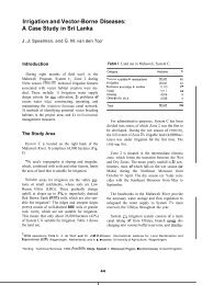
Figure 3. Inundation canal.<br />
,121Vl.R UANK<br />
Figure 4. Head of inundation main carlal.<br />
7<br />
.. .<br />
I
If shoals are present in the river bed, the site of tlie offtake<br />
point should be in front of the shoal as shown in Figure 4. The<br />
shoal will create a pocket in front of the offtake point of the<br />
canal. The formation of the pocket will create a stilling pond,<br />
which will help to reduce the amount of sediment eiiteriiig tlie<br />
canal.<br />
At the offtake point, the width of the river and its velocity<br />
should be normal so that it is not affected by fluctuations in<br />
the water level.<br />
If a river bye-pass is available, the offtake point should be<br />
located on the bye-pass, because this will cause a minimum of<br />
sediment entering the canal.<br />
When the offtake point becomes unserviceable, there should be<br />
no difficulty in locating another offtake point.<br />
Considerations in the design of inundation canals<br />
The main difficulty with an inundation canal is that of sediment<br />
deposition (silt and fine sand) and the formation of a bar at its<br />
mouth when a sudden fall in the river level occurs, which results<br />
from the lack of water level control at the head of the canal.<br />
Further, during floods, more water may find its way through the<br />
canal and submerge vast tracts of land on both sides. Thus, in<br />
order to safeguard against future difficulties, the following<br />
considerations should be considered in the design of an<br />
inundation canal.<br />
A flood regulator (Figure 5) can be provided on the main canal<br />
5 to 6 km downstream from the offtake point. If the flow<br />
regulator is provided at the offtake point, there is a danger of<br />
the same being washed away during floods. The main function<br />
of this regulator is to regulate the flow of water in the main<br />
canal and also to prevent heavy river floods from entering the<br />
main canal.<br />
The flood regulator can be provided with canal vertical lift gates<br />
in tiers (Figure 51 so as to exclude heavy sediment bed loads<br />
from entering the main canal.<br />
A canal escape should be provided just on the upstream side of<br />
the flood regulator (Figure 4). through which surplus flood<br />
a
water, during the closure of the flood regulator, will be disposed<br />
off into the river via a channel.<br />
The full supply level (FSL) of the main canal should be fixed as<br />
the level at which water in the river is more or less steady for a<br />
certain maximum number of days (about 40 to 50 days) during<br />
the inundation season.<br />
The canal bed level at tlie offtake point should be as low as<br />
practicable so that canals rnay get water for a longer time<br />
period.<br />
Full supply discharge of the canal is fixed on the basis of<br />
the requirements of rabi and kharif crops.<br />
The cross-section of the canal is kept liberal because the time<br />
factor in inundation irrigation is very low and uncertain. Further,<br />
the inundation main canal is made deeper and narrower (is, the<br />
B/D ratio is small) than other types of irrigation canals.<br />
The bed slope of the canal is fixed depending upon the slope of<br />
the country, keeping in view that excessive velocities causing<br />
scour should not be allowed. In general, the bed slope provided<br />
for the canal is in the range of 0.1 to 0.25m/km.<br />
Maintenance of inundation canals<br />
As sediment control devices are not provided for in the<br />
inundation canals. there is an acute sediment problem (usually called<br />
silting in Pakistan) in the main canal as well as other channels of an<br />
inundation irrigation system. In the head reaches of the main canal,<br />
usually heavy deposition of sediment takes place, which rnay vary from<br />
0.30 to 1.75 meters in one season. Sediment deposition usually results<br />
III reduced discharge capacity of the ct>aniiel.<br />
Every year, after the end of the inundation season, the removal<br />
of sediment deposits in irrigation channels are undertaken, which forms<br />
the major maintenance work for these canals. Moreover, certain<br />
provisions are made during the construction of the inundation canals for<br />
their proper maintenance which are described below.<br />
9
a) In addition to the main head or offtake point, subsidiary heads<br />
(Figure 4) may be provided which will admit water in the canal,<br />
in case the main offtake point has too much sediment<br />
deposition.<br />
bt<br />
A flood regulator, along with a canal escape, may be provided<br />
a few kilometers downstream of the offtake point. This will<br />
regulate the supply of water as well as control the entry of<br />
sediment into the canal as explained earlier.<br />
cl If there are a number of main inundation canals [say 3 or 41<br />
taking off at different points from the same river, a feeder canal<br />
taking off from the same river may be constructed as shown in<br />
Figure 6, which links all of the main canals and maintains<br />
supplies in these canals in case their head reaches become filled<br />
with sediment. The provision of a feeder canal avoids the<br />
necessity of constructing a number of subsidiary heads; also,<br />
the other canals receive their supplies under a higher head.<br />
2.1.5. Advantages of inundation canals<br />
a1<br />
The various advantages of inundation canals are as follows:<br />
The overall cost of construction of an inundation canal system<br />
is low because no diversion headworks are constructed;<br />
b) The water supplied by these canals contain sediment, which<br />
helps to improve the soil fertility of the agricultural fields; and<br />
cl<br />
Since the canals do not supply water throughout the year. the<br />
problem of waterlogging usually does not arise. Further, there<br />
is less possibility of overirrigation in this case; hence, the bad<br />
effects of overirrigation are reduced.<br />
2.1.6. Disadvantages of inundation canals<br />
a)<br />
b)<br />
The various disadvantages of inundation canals are as follows:<br />
the water supply available from these canals is variable and<br />
unreliable;<br />
As there are no headworks, the offtake point or the head of the<br />
canal are liable to be damaged during floods;<br />
10
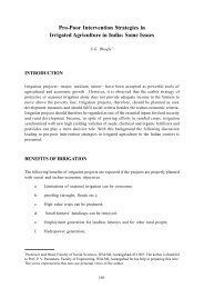
The location map for Fordwah/Eastern Sadiqia is shown in Figure 7.<br />
Fordwah Brarich Canal has a total length of 123 km, 38.4 km of which are iii<br />
the Chishtian Sub-division frorn RD-245 to RD-371 (tail of this branch canal).<br />
The design discharge at RD-199, the indent point for the Chishtian Sub-<br />
division, is 1282 cusecs. The bed width is about 11 5 feet at RD-199, and 50<br />
ft at the tail (RD-371). The average slope is 0.02% (1/5000). <strong>Water</strong> is<br />
distributed to secondary channels (distributaries) through 14 offtakes haviny<br />
vertical sliding gates, culverts or open flumes.<br />
The white marks which were established to calibrate all flow control<br />
structures in Chishtian Sub-division are given in Annex 1, together with the<br />
elevations of these white marks. The locations of these white marks are given<br />
in Annex 2. There are 21 direct outlets (Pipes, APM and OCOFRB) along<br />
Fordwah Branch Canal in Chishtian Sub-division. Their size and corresponding<br />
coefficient of discharge are give in Annex 3. The total GCA (gross command<br />
area) of Chishtian Sub-division is 1,81,369 acres and CCA (cultural command<br />
area) is 1,63,635 acres (Litrico, 1995). Of the 14 distributaries, nine are non-<br />
perennial, which means that they are entitled to draw water during the kharif<br />
season only, and five are perennial, which draw water all year (Table 1).<br />
The command area of each distributary in Chishtian Sub-division is<br />
shown in Figure 8. while a schematic of Fordwah Branch Canal is provided in<br />
Figure 9. The water levels are riiairilaiiied aloity tlie calla1 by iiieaiis 01 live gate<br />
cross regulators and two weirs. Most of the distributaries offtake Just<br />
upstreani of a cross regulator; only three of them (Phogan, Jagir and Soda) are<br />
not under the direct control of a regulator. The seepage in this canal, measured<br />
using the inflow-outflow method, is about 9.3 cusecs per million square feet<br />
of wetted perimeter (Calibration of Structures, IIMI, 1995).<br />
13
-. ~<br />
. ,<br />
. . . . .<br />
-1
Fordwah Disty (P) * Mehmud Disty [P,RD371]<br />
Azim Disty [NP,RD371]<br />
5-L Disty [P,RD 3481<br />
Weir [RD 3341<br />
4-L Disty [NP, RD 2811<br />
3-L Disty [NP,RD 2451<br />
*<br />
ir<br />
[RD 3541<br />
Main Fordwah Branch Canal<br />
Soda Disty [NP,RD 3341<br />
Masood Disty [P,RD 3161<br />
shahar Farid Disty [NP,RD 3161<br />
Jagir Disty [P, RD 2971<br />
Khemgarh Disty [NP, RD 2811<br />
Phogan Disty [NP,RD 2671<br />
Mohar Disty [NP,RD 2451<br />
Daulat Disty [NP,RD 2451<br />
Laqend: Desiqn discharqe (Cusecs):<br />
* = Gate structure Daulat=209,Mohar=38.3-L=18<br />
- = Weir Phogan=18,Khemgarh=24,4-L=14<br />
NP= Non perennial Jagir=28,shahar Farid=153<br />
P = Perennial Masood=35,Soda=77,5-L=4,Mehmud=9<br />
Fordwah disty=158, Azim=244<br />
Total discharge=1029<br />
Figure 9. Layout of Fordwah Branch Canal in Chishtian Sub-division.<br />
17
2.3. Reasons for Perennial and Non-Perennial Channels<br />
The Fordwah Division is a mixture of perennial and non-perennial<br />
channels. The non-perennial channels get water only in the kharif season (from<br />
mid-April to mid-October) through the Fordwah Canal from Suleiinanki Head<br />
Works. But perennial channels, which are located only in Chistitian Sub-<br />
division, also obtain water through the Sadiq Ford Feeder offtaking from Sadiqia<br />
Canal during the rabi season (from mid-October to mid-April). The different<br />
reasons for this are given below:<br />
a1 There is not enough water available during the rabi season to supply all<br />
distributaries;<br />
b)<br />
c)<br />
d)<br />
The ground water quality along perennial distributaries was not good;<br />
Along non-perennial distributaries, there were a lot of open wells and<br />
ground water quality was comparatively good; and<br />
Non-perennial distributaries were having a waterlogging problem, so not<br />
having canal flows during the rabi season helped to relieve this problem.<br />
18<br />
I
i I<br />
CHAPTER 3: ORGANIZATIONAL ARRANGEMENTS<br />
3.1. Organization of Bahawalnagar Circle<br />
There are different levels of management units in the Punjab lrrigatioii<br />
System. The Zone is the biggest unit, and a Chief Engineer is incharge<br />
of it. The Circle is the next unit, headed by a Superintending Engineer<br />
(SE).<br />
Then comes the Division, which is the basic irrigation unit. headed<br />
by an Executive Engineer (XEN). A Division is divided into Sub-divisions,<br />
headed by an Assistant Executive Engineer called Sub-divisional Officer<br />
(SDO).<br />
Actually, Bahawalnagar Circle is a mixture of perennial and non-perennial<br />
units of the Sutlej Valley Project. There are three divisions in<br />
Bahawalnagar circle namely as; (1 Eastern Sadiqia Division’, (2) Hakra<br />
Division, (3) Fordwah Division. The organizational chart of Bahawalnagar<br />
Circle is given in Figure 10. The total GCA and CCA for each Division is<br />
given in Table 2, while total GCA and CCA for each Sub-division it1<br />
Fordwah Division is given in Table 3. There are a total nine Sub-divisions<br />
in Bahawalnagar Circle:<br />
Jalwala Sub-division (mixture of percnnial and non-perennial channels)<br />
of Eastern Sadiqia Division;<br />
Malik Sub-division (totally perennial channels) of Eastern Sadiqia Division;<br />
Dahranwala Sub-division (totally perennial channels) of Eastern Sadiqia<br />
Division;<br />
Haroonabad Sub-division (totally perennial channels) of Hakra Division;<br />
Faqirwali Sub-division (totally perennial channels) of Hakra Division;<br />
Fort Abbas Sub-division (mixture of perennial and non-perennial<br />
channels) of Hakra Division;<br />
Minchinabad Sub-division (totally non-perennial channels) of Fordwah<br />
Division;<br />
Bahawalnagar Sub-division [totally non-perennial channels) of Fordwah<br />
Division; and<br />
SDO drainage is also working under the supervision of the XEN Sadiqia.<br />
19
3.2. Organization of Chishtian Sub-division.<br />
The Sub-division is headed by an Assistant Executive Engineer called<br />
Sub-divisional Officer ISDOI. Chishtian Sub-division is divided into five<br />
operating and maintenance (sub-engineer‘s) sections, each of them<br />
headed by a Sub-engineer. These Sub-engineers provide help to the SDO<br />
in technical and other related matters. And it is also divided into three<br />
Zilladari [revenue) sections, each of them headed by a Zilladar. These<br />
Zilladars provide help in the matters related to the revenue and<br />
agricultural tasks. The complete details about operating & maintenance<br />
and revenue sections are given below. The organizational chart for<br />
Chishtian Sub-division is shown in Figure 1 1, while the detailed list of<br />
the regular establishment of Chishtian Sub-division is shown in Table 4.<br />
Operating and Maintenance (Sub-engineer’s) sections of Chishtian Sub-division<br />
are:<br />
1.<br />
2.<br />
3.<br />
4.<br />
5.<br />
Operating and Maintenance (Sub-engineer‘s) Takhat Mahal Section;<br />
Operating and Maintenance (Sub-engineer’s) Khemgarh Section;<br />
Operating and Maintenance (Sub-engineer’s) Chak Abdullah Section;<br />
Operating and Maintenance (Sub-engineer’s) Chishtian Section: and<br />
Operating and Maintenance (Sub-engineer’s) Hasilpur Section.<br />
Revenue (Zilladari) sections of Chishtian Sub-division are:<br />
1. Revenue (Zilladari) Kherngarh Section;<br />
2.<br />
3.<br />
Revenue (Zilladari) Chishtian Section; and<br />
Revenue (Zilladaril Bakhshan Khan Section.<br />
22
According to tlie Table 4, the Chishtian Sub-division is having a number<br />
of staff involved in different activities related to administraLive maiters,<br />
operating & maintenance work, agriculture tasks and revenue. There arc five<br />
sections related to operating & maintenance. Each section is headed by a Sub-<br />
engineer.<br />
A Sub-engineer is an important person, who is related more with field<br />
activities at the section level. The Sub-engineer visits his assigned area by using<br />
his own personal motor bike or car (if he belorigs to a ricli farriily). He also visits<br />
the SDO office to get instructions from the SDO related to his section or about<br />
the visits of XEN or SE and Chiel Engineer etc. for preparing various things<br />
accordingly. He also reports lo the SDO about all kinds of maintenance &<br />
operating work in advance with all details like installation of gauges, berm<br />
cutting & silt clearance, rehabilitation work in different reaches of clilforent<br />
channels, checking side erosions, repairing the head regulation points and slabs,<br />
painting oiling & greasing regulation gates, repairing pilchi pitching RC killa<br />
hushing in different channels, steel lining & repairing of tampered outlets and<br />
employing workcharge seasonal establishment with estimated aniounts. The<br />
SDO also checks at the site and sends it for approval to the XEN. Wlren the<br />
XEN approves the amount, then PlPD get this work done through any<br />
Government Contractor. The SDO can approve a certain amount of money in<br />
case of emergency for spending for closing & strengthening sudden breaches<br />
etc.<br />
There are only 5 Gauge Readers in Chishtian Sub-division. Actually, the<br />
Gauge Readers are mostly local (belonging from the sarne area in whicli they<br />
have to work). The Gauge Reader is having an important role to run the<br />
irrigation system. The Gauge Readers at cross regulators live at the sarne place<br />
to take care of canal water 24 hours. Most of the Gauge Readers are<br />
experienced in their related work. Although in Chishtian Sub-divisiori, there is<br />
a lack of communication, but these Gauge Readers can ur:derstand just by<br />
looking at the type of fluctuation, what is happening in upstream reaches of a<br />
channel. The Gauge Reader keeps the record of daily discharge positions<br />
(according to the discharge tables provided him tliroagli the SDO or Sub-<br />
engineer and approved by the XEN) in his reach and tries to handle the availah!e<br />
water according to the instructions made by the SDO or Sub-engineer. But<br />
sometimes, when a breach occurs in any offtaking chaririel (dire to sudden<br />
excess of water without any information, or weakness of the bank of a<br />
channel), the Gauge Reader also tries to handle and to satisfy the farmers (who<br />
become emotional due to damaging of their crops and property with the water<br />
from the breach) and also sends someone to inform the SDO office and the<br />
Signaller for further action.<br />
25
There are 4 Mates (considered more responsible as compared to the<br />
Beldars), who supervise the Beldars (uneducated persons but work like<br />
labourers) which are a total of 33 in Chishtian Sub-division. The Mate and the<br />
Beldars (also local people) take care of the channels. Beldars put soil or tree<br />
branches at weak berms, banks and broadcast canal water on the canal bank<br />
due to dust in his assigned area. The Mate and the Beldars also get the help of<br />
farmers in case of a breach in order to closc it. The Mate also looks after the<br />
maintenance & repair work according to the orders of the Sub-engineer. The<br />
SDO also sends the Beldars of one section to another section for working<br />
according to the situation.<br />
There are 3 Signallers in the Chishtian Sub-division. The Signaller is also<br />
an important person, who keeps an eye through the Telegraphic System about<br />
the activities in the field. He also conveys the messages of the SDO’s to other<br />
related staff in a very short time, but only if the Telegraphic System works in<br />
a good way. He also receives daily gauges & discharges position of all cross<br />
regulators and offtaking channels with their tail positions (depth of water at tail<br />
in feet). He also records all of these collected information (from the field) in a<br />
official Gauges Register. Then he shows to the SDO how much water they are<br />
receiving (from RD-I 99 + 81 2. the indent point of Chishtian Sub-division) and<br />
how it is distributed within the Chishtian Sub-division. The Signaller also<br />
receives by hand the gauges & discharge positions of each cross regulator and<br />
offtaking channels, due to any fault in the old Telegraphic System. He also<br />
keeps a record of the visits of their senior staff. He also informs (in the main<br />
Telegraphic Office Bahawalnagar) about reducing the discharge from upstream<br />
in case of a sudden breach or heavy rain in the Chishtian area.<br />
The Sub-divisional Clerk (SDC), Sub-divisional Reader (SDR) and<br />
Assistant Vernacular Clerk (AVCI are support staff. They keep the records [of<br />
whole Sub-division) of the salaries of staff, letters from higher officials, other<br />
revenue matters related to farmers and also keep the records of official<br />
warabandi of each individual outlet (watercourse) along each channel in<br />
Chishtian Sub-division. They also tell to the farmers (who do not know how to<br />
write an application to the SDO) for changing the warabandi time within a<br />
watercourse due to an increase in the GCA (of the said watercourse).<br />
complaining to the SDO about the theft of water within a watercourse by the<br />
tenants & servants of big or influential farmers during their water turn (of those<br />
farmers who are complaining) for whole sub-division and then the SDO sends<br />
someone to check physically the site and take necessary action according to<br />
his powers, or send that case to the XEN for further action.<br />
26
There are 3 Zilladars for the whole Chishtian Sub-division. The Zilladar<br />
is the person incharge of the reveiiue section related to agricultural tasks. Each<br />
Zilladar supervises 9 or 10 Patwaris. It is the responsibility of the Zilladar to<br />
check the accuracy of the work, like the area map of each chak boundary,<br />
warabandi schedule of each Farmer according to the land holding at each<br />
watercourse or outlet, Khasrah Register and Thur Girdawari Khasrah register<br />
which has already been updated by his Patwaris, as well as all other related<br />
matters. He also helps the new Patwaris who work under his supervision.<br />
All of the other staff members are support staff, who take care the<br />
office, the equipment used for different kinds of work, mail and other official<br />
works assigned by the SDO.<br />
3.2.1 Operation and Maintenance Section<br />
The Chishtian Sub-division is divided into five operating seciioirs. FOI<br />
each section, there is a Sub-engineer who is responsible for operation and<br />
maintenance of his section. Each concerned Sub-engineer visits his area of<br />
responsibility and tries to provide the canal water according to the schedule<br />
made by the SDO in his sub-division. Sometimes, the Sub-engineer makes<br />
changes in the schedule after discussing with the SDO regarding the supply of<br />
water for his section due to heavy rains, repairing of broken outlets,<br />
unexpected breaches, etc. The SDO sends a weekly program to the Executi-.e<br />
Engineer (XENJ about the demand for water (total discharge) through the<br />
Signaler for his sub-division after discussing with all of his Sub-engineers.<br />
The total lengths of all five operating & maintenance sections are:<br />
1) Sub-engineer Takhat Mahal Section, total length is 200 -c 780 feet;<br />
2) Sub-engineer Khemgarh Section, total length is 194 + 530 feet;<br />
3) Sub-engineer Chak Abdullah Section, total length is 176 + 790 teet;<br />
4) Sub-engineer Chishtian Section, total length is 194+040 feet; and<br />
5) Sub-engineer Hasilpur Section, total length is 1744- 300 feet.<br />
The farmers located in the tail reach of Fordwali Distributary visited the<br />
PlPD Chief Engineer's office at Bahawalpur about the shortage of canal water<br />
at the tail of Fordwah Distributary bccause of being a perennial chaniiel. So,<br />
due to this reason, the Chief Engineer visited at the beginning of rabi 1995-96<br />
the tail area of Fordwah Distributary in the presence of the Superintending<br />
Engineer (SE) and all other PlPD staff. The Chief Engineer officially handed over<br />
the control of Fordwah Distributary from head to tail, together with its Jiwail
Minor, to the Sub-erigineer (t-lasilptir) for taking responsibilily to overcome tail<br />
shortages. Previously, the head area of Fordwah Distributary was under the<br />
control of the Sub-engineer (Chishtianl. The details about the operating and<br />
maintenance sections of all five sub-engineer's are given in Table 5.
Table 5. Operating and maintenance sections of Chishtian Sub-division<br />
Sub-Engineer. Chak<br />
Abdulloh Scction<br />
Ib-Englneer. Has8lpw<br />
mtion<br />
" . .~<br />
Mohor Distributary<br />
iub-Enginser. Chishtian Fordwah Branel> Canal<br />
,emion<br />
5-L Distributary<br />
I<br />
RD-352t000 lo 371 b650 19+650<br />
Itaill<br />
RD-0 lo 1 I +300 (tail) 11 +300<br />
Masood Distributary RD-35+000 to 45+950 (laill 10+9~0<br />
Mehrnud Distributary<br />
- RD-o to I I +nso ftoill<br />
11+860<br />
Aim Dtr.lrilnaiilry<br />
Rathi Miriar<br />
Feroic Minor<br />
Forest Minor<br />
Fardwah Distributary<br />
Jiwan Minor<br />
I RD~O tu 55+000 55 + 500<br />
I<br />
1 RD-0 to 20~240 Itaill 20 + 240<br />
I II<br />
RD-0 to 43 +800 lta,l)<br />
43 + 800<br />
I<br />
Shahar Farid Distributary I RD-47+000 to 74+880 (tail) 27+880<br />
..<br />
I<br />
I nayeiwsh Minor 1 RD~O to 32 t 180 ftaill 32+180<br />
29<br />
RD n IO I t R 9 380 I~,~:II I IR I 9.90<br />
RD-0 to lOt.000 Itacl)<br />
RD-0 to n +OOO itail)<br />
RD-0 lo 3+300 Itail)<br />
RD-0 to 139 t780 (tail)<br />
RD-0 to 34.1520 Itail)<br />
10+000<br />
8 +ooo<br />
3 i 300<br />
139 +780<br />
34 + 520
CHAPTER 4: COLLECTION OF INFORMATION<br />
There are different kind of information, which are being collected by the<br />
field staff of PIPD. The information being discussed in this chapter are:<br />
Gauges (water levels);<br />
* Khasrah (crops survey);<br />
*<br />
Thur Girdawari Khasrah (visual observation of salinity for each field);<br />
Outlet Register (GCA. CCA, size, location, design discharge and crest<br />
reduced level (CRL) etc. of each outlet in the Sub-division);<br />
'H' Register (data about water level of each outlet etc.);<br />
* Sub-engineer's Outlet Note Book (GCA, CCA, size, location, design<br />
discharge and crest reduced level (CRLI etc. of each outlet in his<br />
section); and<br />
* Communication System (backbone of the Punjab Irrigation System but<br />
not in good working condition).<br />
4.1. Gauges<br />
The Punjab Irrigation and Power Department (PIPD) staff are using<br />
gauges for periodically (once a day or more often) reading water levels<br />
(discharge position) of cross-regulators (CR) along Fordwah Branch Canal and<br />
for the head regulator (HR) of each distributary and minor including their tail<br />
gauges. The present position of gauges in Chishtian Sub-division is given in<br />
Table 6.<br />
Table 6 shows the present condition and positions of gauges at all of the<br />
cross regulators, head regulator of offtaking channels and their tails in the<br />
Chishtian Sub-division. At some places, there are no gauges.<br />
The total height of the gauge is 9 feet which is installed on the left wall,<br />
upstream of the cross regulator of Fordwah Branch Canal at RD-245 + 500.<br />
This gauge is installed with reference of the crest of the cross regulator. The<br />
total height of the downstream gauge is 8.5 feet, which is installed in a well<br />
downstream of the cross regulator at RD-245 i 500 of Fordwah Branch Canal.<br />
This downstream gauge is buried 5.5 feet in the sediment. So, if the depth of<br />
water at this point is less than 5.5 feet, then it is not easy to read the gauge<br />
accurately. The gauge installed about 200 lee1 downstreani (left side of the<br />
30
-<br />
S.No. Designation of Partal quota of Partal quota of Khasrah<br />
Staff Khasrah for Rabi for Kharif<br />
KhaarnlPukhta (acres) KhaamiPukhta (acres)<br />
1 Executive Engineer 5001300 (for the 500/300 (For the entire<br />
(XEN) entire division) division)<br />
2 Sub Divisional 150011000 (For the 15OOl1000 (For the<br />
Officer (SDO) entire sub-division) entire sub-division)<br />
3 Deptrty Collector 600014500 (For the 6000l4500 (For the<br />
entire division) entire division)<br />
4 Zilladar 400013000 (For the 4000/3000 (For the<br />
oritire sccLion) elitire scctioii)<br />
33
4.2.2. Thur Girdawari Khasrah3<br />
The Thur Girdawari Khasrah is a printed register provided by the<br />
Divisional office through the Zilladar to cacti cw1cernwI Catial Piitwari for<br />
visual observation of salinity for each field in his assigned halqa. The<br />
Canal Patwari visits his halqa for Thur Girdawari Khasrah once a year in<br />
December, January or February when salinity is most visible. He notes<br />
the salinity according to specific classes as defined in Table 8, for each<br />
single field (acre4). After completing the Thur Girdawari Khasrah fi-om<br />
each field, the Canal Patwari submits the Thur Girdawari Khasrah to the<br />
concerned Zilladar, who makes a complete statement for each channel<br />
in his section and sends this to the SDO and then the XEN. The Thur<br />
Girdawari Khasrah can be checked physically by the XEN, SDO, LRO<br />
(Land Reclamation Officer), ALRO (Assistant Land Reclamation Officer).<br />
Zilladar Reclamation and Zilladar from their normal partal quota (checking<br />
about 20% of the quantity of work). Then, the Assistant Land<br />
Reclamation Officer sends the Reclamation Zilladar and Patwari to<br />
physically check the Thur Girdawari Khasrah (which has already been<br />
done by the Canal Patwari). Both the Reclamation Zilladar and Patwari<br />
prepare a statement (based on the collected visual observation of<br />
salinity) regarding strongly saline fields for each outlet (watercourse<br />
command area) and submit this list to the Land Reclamation Officer for<br />
further action. Then, the LRO visits the XEN's office and shows the list<br />
of demand for extra water supply channel wise under each outlet. The<br />
XEN approves some extra water according to the capacity of each<br />
selected channel. After getting the approval from the XEN, the LRO<br />
sends his Reclamation Zilladar and Patwari to have a meeting with the<br />
farmers of the selected outlets in their halqa about the rules regarding<br />
extra water supply using seasonal pipes. The rules are:<br />
a) The farmer will use the extra canal water only for selected saline<br />
fields.<br />
bl The farmer will sow rice in saline fields for which the Land<br />
Reclarnatioii Directorate has approved extra canal water (with<br />
a ratio of one cusecs for 45 acres for three months from the<br />
15th of July to the 15th of October).<br />
' Salinity assessment made through visual soil salinity surveys undertaken during the months of<br />
December, January and February when tlie salinity is most visible.<br />
' The basic administrative unit of the irrigation system with dimensions 67m x 60177<br />
34
Cl The farmer will get this opportunity for a maximum of three<br />
years (that is three months during kharif every year up to three<br />
years).<br />
d) The farmer will pay a “leaching” (reclamation) fee of 35<br />
rupees/acre for using this extra canal water for three months<br />
together with abyana for the kharif season.<br />
e) If at one outlet there is more than one farmer, they will get<br />
warabandi time (total time of each farmer for using canal water)<br />
for that seasonal outlet according to tP..e land holding made by<br />
the Canal Patwari. The Patwari (Land Reclainationl will check<br />
during these three months, that farmers are using the water<br />
from the seasonal outlet on selected saline fields.<br />
1 ) Alter the 15111 of October, tlie seasonal pipe will be removed by<br />
PlPD staff and will be installed again in the second year on the<br />
15th of Julv.<br />
The purpose of Thur Girdawari Khasrah is: (i) to assess the<br />
extent of salinity ano waterlogging in canal coinmand areas: and (ii) to<br />
plan, organize and monitor the allocation of extra canal water supplies<br />
(or reclamation shoots) to salinity affected areas, in coordination with the<br />
operating staff of the Punjab Irrigation & Power Department. The ALRO<br />
makes a statement showing how much area has been improved due to<br />
providing seasonal outlets for reclaniation shoots) in his circle.<br />
One year before, The former Chief Minister of Punjab stopped<br />
providing seasonal pipes/outlets saying that “Some farmers are misusing<br />
this opportunity”. But now, from kharif 1996, it has again started. An<br />
example of Thur Girdawari Khasrah is shown in Annex 5.<br />
Table 8. Salinity classes used for Thur Girdawari Khasrah.
4.2.3. Outlet Register<br />
A printed outlet register is supplied by the concerned division to<br />
the concerned sub-division and retained by the revenue clerk at the<br />
division office, while the SDO maintains the outlet register by himself.<br />
The outlet register contains the following data: the name of distributary:<br />
supply factor; intensity; kharif rabi ratio; serial number; location (RD) of<br />
outlet; side of outlet (left or right or front etc.); name of village (chak);<br />
GCA of outlet; CCA of outlet; date of construction or alteration;<br />
authorized discharge; type of outlet; reduced level IRL) of crest of outlet;<br />
description and reduced level of referring bench mark; size of outlet that<br />
is "8" (width), "Y" (height); "H" (depression head of outlet); working<br />
head and setting of outlet ('H' of outlet/full supply depth in distributary<br />
100).<br />
The Sub-engineer obtains a copy through his SDO about outlet<br />
changes in his section and updates his own outlet note book. The Sub-<br />
engineer has to compare his outlet note book with the outlet register of<br />
the sub-division once a year. Then, the Sub-divisional Reader will<br />
compare the outlet register of his sub-division with the divisional outlet<br />
register. An example of an Outlet Register is shown in Annex. 6.<br />
4.2.4. 'H' Registei<br />
The 'H' Register is a printed register designed for water level<br />
(called head) 'ti' observations by the Sub-engineer in his section, which<br />
is supplied by the divisional office through the head clerk. The 'H'<br />
observations are observed and measured in February, May, August and<br />
November of each year. After observing the heads 'H'# of the outlets and<br />
structures for all of the channels in his section, the Sub-enginc?er siihniits<br />
his 'ti' Register to the Sub-divisional office. Then, the SDR (Sub-<br />
divisional Reader) also enters the observed H's in his register for all of<br />
the channels in the sub-division and returns the 'H' Register to the<br />
concerned Sub-engineer. The SDO may check these recorded<br />
measurements during his inspection of the channels. The supply at the<br />
head of a channel must be run constant with its design discharge, or<br />
indented discharge 24 hours before the 'H' observations. After placing<br />
the H's in the Register for the entire Sub-division, the SDR sends the 'H'<br />
Register to the Division Office for their entering the H's. After completing<br />
the 'ti' Register, the XEN sends the divisional 'H' Register to the Circle<br />
Office for entering the H's in the Circle Office 'H' Register. After<br />
completing the 'H' Register of tho Circle Offict!, tlie divisional 'H'<br />
Register is sent back to the concern division. But nowadays. the 'H'<br />
Register is not maintained in Ctiishtian Sub-division.<br />
36
4.2.5. Sub-engineer's Outlet Note Book<br />
The Sub-engineer Outlet Note Book is supplied from the Division<br />
Office by the head clerk to the concerned Sub-engineer, which he<br />
maintains. All outlet alteration forms are entered in the Outlet Note Book<br />
after making any changes, such as the size of outlet, with dated<br />
signature. The Sub-engineer will compare his Outlet Note Book with the<br />
sub-divisional Outlet Register once a year and to record his certification<br />
about the comparison made on such a date. A Sub-engineer has to keep<br />
the Outlet Note Book in his basta (bag) during the inspection of his<br />
section, as well as for officers inspecting in his section. The Outlet Note<br />
Book is maintained as a measurement book, which is a very important<br />
record for the section. In this Outlet Note Book is recorded: the name of<br />
distributary; serial number; location (RD) of outlet; side of outlet (left or<br />
right or front etc.); name of village (chak); CCA of outlet; authorized<br />
discharge of outlet; date of construction or alteration; type of outlet;<br />
reduced level (RL) of crest of outlet; size of outlet that is "6" (width),<br />
"Y" (height); "H" (depression head of outlet); .working head of outlet;<br />
remarks column to include sanctioning authority and date, signature of<br />
subordinate carrying out the work. An example is shown in Annex. 7.<br />
4.3. Communication System *?<br />
The communication system for Chishtian Sub-division is depicted in<br />
Figure 12. This figure is marked with (a), (b), (c) ,... (i) and the text below has<br />
been written in accordance with this notation. Thus, the text can be related to<br />
Figure 12.<br />
a)<br />
b)<br />
There is an old telegraphic system located at RD-l99+812 of Fordwali<br />
Branch Canal in the room of the Gauge Reader. He is taking gauge<br />
readings twice a day at morning and evening, and recording them in an<br />
ID register. The Gauge Reader transmits the discharge position twice a<br />
day this place to the main telegraph office in Bahawalnagar. The Gauge<br />
Reader states how much water is being received from upstream and how<br />
this water is being subdivided to other offtakes according to the orders<br />
of his SDO or XEN. The Gauge Reader stated that this telegraphic<br />
system is riot reliable because sonietimes it works and sometirnes it does<br />
not work.<br />
The main telegraph office at Bahawalnagar has foLir telegraphic sets<br />
which are connected with all of the Bahawalnagar Circle telegraph<br />
offices. The main office receives daily discharge positions along the<br />
elitire Fordwah system, including all offtakes iii the vaiious sub-divisioris,<br />
and compares with the Rotation Schedule (see Annexure 8) for that<br />
season. Here, they are maintaining a Register including daily discharges,<br />
37
cl<br />
dl<br />
which they receive from the field offices through the telegraphic system<br />
or from other different sources. From this office, they convey<br />
information about the field visits of senior staff along any offtake, other<br />
orders about closing or opening the distributaries, and about increasing<br />
or decreasing the discharge during any emergency. But this<br />
communication system is not working very well due to some faults.<br />
The Signaler at the SDO Chishtian office disclosed that about 14 years<br />
ago tho telegraphic system at this place (Takhat Mahal Sub Rest Hoc~se)<br />
was in working order and a person was working there as a signaler of<br />
Takhat Mahal Section. And he was receiving gauge readings of Cross<br />
Regulator at RD-245 + 500 of Fordwah Branch Canal, along with daily<br />
discharge positions of Daulat, Mohar and 3-L distributaries, through a<br />
telephone which was installed in the room of the Gauge Reader at RD-<br />
245 + 500 of Fordwah Branch at that time. The Signaler of Takhat Mahal<br />
was receiving the discharge readings about Phogan Distributary which<br />
offtakes from RD-267 + 725 of Fordwah Branch Canal, through the<br />
beldars of that area. And this Signaler was also receiving the discharge<br />
readings of Khemgarh and 4-L Distributary which offtake from RD-<br />
281 +OOO of Fordwah Branch (and also the discharge of Cross Regulator<br />
at RD-281 +OOO), through any responsible person. So, the Signaler of<br />
this area was covering from RD-245+500 to RD-281 +OOO of Fordwah<br />
Branch Canal, including all offtakes, and was always getting in touch<br />
with the Signaler of Chishtian to inform him about the water situation in<br />
his reach. He was also conveying all instructions to the related staff after<br />
receiving them from the Chishtian SDO office.<br />
At this point, there was also a telegraphic system, which is not working<br />
anymore. Now, this Gauge Reader is sending daily data to the Chishtian<br />
SDO from different sources about his reach. So, if any breach occurred<br />
in his reach in any distributary, the Gauge Reader closes any distributary<br />
which will be affected due to the breach because of stress from the<br />
farmers. Then, that water will be released into the main branch without<br />
informing any downstream gauge reader, who may not be able to handle<br />
this emergency situation. This is all due to not having proper<br />
communication among the gauge readers and the responsible staff in tlie<br />
offices.<br />
e) At this time, the Signaler gets the daily gauges from the Gauge Reader<br />
at RD-316+380 of Fordwah Branch Canal. The Signaler collects the<br />
information through a telegraphic system to the Chishtian ID office. But,<br />
sometimes, when the telegraphic system at this point has problems, then<br />
the Gauge Reader sends the gauges data to the ID Office, Chishtian by<br />
any means in order to inform them about the discharges in his reach.<br />
38
RD-199+812<br />
I Fordwah Branch I<br />
RD-245+500<br />
(d) .....<br />
RD-371+650 tail<br />
(4)<br />
in working condition<br />
...... Not in working condition<br />
Main telegraph office<br />
Bahawalnagar<br />
(b)<br />
Chak Abdullah Resthouse<br />
Telegraph office<br />
......<br />
Rest House<br />
telegraph office<br />
Figure 12. Communication System in Chistitian Subdivision.<br />
39
f) The Signaler obtains discharge positions daily through the telegraphic<br />
system and by other sources in Chishtian Sub-division. The Signaler<br />
conveys messages to the Gauge Readers on behalf of the SDO Chishtian<br />
for controlling water deliveries in a better way due to liis experience. The<br />
Signaler also enters these daily discharges for all offtakes in a register.<br />
The Signaler writes the information received from the Gauge Rcaders, so<br />
the reliability of the field data depends on these Gauge Readers. The<br />
Signaler also informs the SDO about daily discharge positions and also<br />
requests to the Bahawalnagar ID office, on behalf of the SDO, for the<br />
total indent of Chishtian Sub-division. But. this old wire system also has<br />
problems sometimes.<br />
g)<br />
There was also an old telegraphic system in working order at RD-<br />
371 +650 (tail of Fordwah Branch Canal). So, the Gauge Reader at this<br />
point was bound to inform daily to the SDO office about the discharge<br />
position in his reach. But, for more than ten years, this wire system is<br />
also not working and the Gauge Reader is visiting daily the SDO office<br />
to inforrn about the discharge in his reach. The Gauge Reader of this<br />
point stated that, for more than fifteen years, the tail is receiving a lot<br />
of problems due to excess water from upstream without any<br />
information. Fifteen years earlier, the Bahawal Ford Feeder Canal was<br />
working and anytime when excess water was received from upstream,<br />
he was passing that water into the Feeder Canal to save the other<br />
distributaries from a sudden breach. But now, the Feeder Canal is not<br />
working; therefore, many times when excess water reaches the<br />
distributary, there are breaches. Especially Azim Distributary has<br />
breaches due to a periodic excess of water at the tail of Fordwah Branch<br />
Canal.<br />
h) ’ At this point there was also an old telegraphic system in the rest house<br />
and the Signaler of this point was receiving the gauge positions of Jiwan<br />
Minor, and RD-64+050 (fall structure) of Fordwah Distributary (and its<br />
tail) and the tail of Azim Distributary together with its minors through ID<br />
Gauge Readers and Beldars. He was conveying this field informatioi) to<br />
the Chishtian Signaller office daily. But now, this telegraphic system is<br />
also not working anymore since fourteen years ago. But ID staff are<br />
recording the gauges for these points from other sources.<br />
i) There is also an old telegraphic system in the Zonal Office at<br />
Bahawalpur, which is in working condition. At this office, the Head<br />
Signaller was receiving discharge readings from Suleimanki Headworks,<br />
main canals and branches from the main telegraph office in<br />
Bahawalnagar for keeping his records updated. He was also informing<br />
the PlPD Chief Engineer, Bahawalpur at his office. Sometimes, the<br />
40
farmers of the tail reach visit the Chief Engineer, Bahawalpw to claim<br />
about tail shortages. So, due to the visits of farmers, the Head Signaller<br />
of the Zonal Office sends a copy of the written orders of the Chief<br />
Eiigiiiccr lo Ualrawalliiigar (or tlic SE, XEN aiid SDO Cliistitiaii tlirougli<br />
the telegraphic system (if it works, otherwise through the mail).<br />
Note: Now the PlPD staff can use the telephone for different messages in case<br />
of problems in the old telegraphic system. They have this facility in<br />
Bahawalpur, Bahawalnagar and Chishtian. Otherwise, they are<br />
communicating through the mail.<br />
41
CHAPTER 5: DESCRIPT!ON OF STRUCTURES<br />
5.1. Types of Structures<br />
The structures constructed to regulate the discharge, full supply level or<br />
velocity of flow in a channel are known as regulation works. Such structures<br />
are necessary for the efficient working and safety of the channel. The various<br />
regulation works discussed in this chapter are as indicated below.<br />
5.1.1, Falls or Drops<br />
A fall is a structure constructed across a channel to permit<br />
lowering of the water level and dissipate the surplus energy possessed<br />
by the falling water, which may otherwise scour the bed and banks of<br />
the channel. However, there are different types of fall structures.<br />
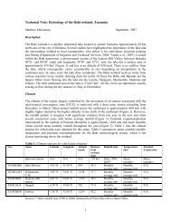
Complete drawings and the longitudinal section for the fall structure at<br />
RD-334+040 of Fordwah Branch Canal is shown in Figure 13.<br />
5.1.2. Cross Regulators and Distributary Head Regulators<br />
Cross regulators and distributary head regulators are provided to<br />
control the supplies moving down the parent channel and the offtakiny<br />
channel, respectively (Figure 14). A cross regulator is provided on the<br />
parent channel at the downstream side of the offtake to head up the<br />
water level and to enable the offtaking channel to draw the required<br />
supply. A head regulator is provided at the head of the offtaking channel<br />
(e.9. distributary) to control the supplies entering the offtaking channel.<br />
Complete drawings and longitudinal section of the head regulator<br />
(controlled with karries) of 3-L Distributary are shown in Figure 15, while<br />
the longitudinal section of the entire 3-L Distributary is shown in Figure<br />
16. Complete drawings and longitudinal section of the head regulator<br />
(controlled with gate) of Masood Distributary is shown in Figure 17 and<br />
a complete longitudinal section of the entiie Masood Distributary is<br />
shown in Figure 18.<br />
The functions of cross regulators are listed below.<br />
al<br />
A cross regulator enables the effective regulation of the watel<br />
level ugstreani from the structure.<br />
b) When the water level in the parent channel is low, they help to<br />
raise the 'water level and feed the upstream offtaking channels<br />
to meet tlieir full water demand.<br />
42
DETAIL OF FALL STRUCTURE AN0 VIUAGE ROAD<br />
BRIDGE AT RD- 334.040 FOROWAH BRANCH CANAL<br />
LONG SECTION OF FALL<br />
CRETE 015'<br />
FigcJre 13.<br />
Drawings of fall structure, village road bridge and lor~girudinal sectioll of<br />
fall RD-334 i~ 040 of Fordwsh Branctl Canal.<br />
43
OFFTAKE /<br />
CHANNEI~ /<br />
Figure 14. Offtaking alignments.<br />
\<br />
44<br />
CFF TAKF ,'
L-SECTION OF 3-L DISTRIBUTARY<br />
OFFTAKES AT R D-245 .SO0 OF<br />
FORDWAH BRANCH CANAL<br />
./<br />
1<br />
190.0<br />
c 80.0<br />
}- II 16 I6 ,-BE0 SLOPE<br />
0.8s' ,<br />
-FS. DISCHARGE<br />
1 -v~Loc I r y<br />
I<br />
t s 00 -c.v R<br />
.4. 0<br />
-3ANK WIDTH<br />
I- 1 5' -FREE 0OARO<br />
Flgure 16 Longitudinal sectton of 3-L Distribulary [from head lo OIC design tail1<br />
offraking at RD-245-500 of Fordwah Branch Cdndl
HEAD REGULATOR OF MAS000 DISTRIBUTARY OFFTAKES Al<br />
R.D 316480 OF FORDWAH BRANCH CANAL<br />
LONG SECTION OF HEAD REGULATOR<br />
OF MAS000 OISTRIBUTARY,<br />
, ,I llR!.ZL .:<br />
I ,’<br />
I ,<br />
I ,’<br />
Figure 17. Drawings 01 the head regulator and longlrudmal sectlot1 of tile head<br />
regulator of Masood Distributary offtakllly at RD 31 G-I 380 of Fords,Jall<br />
Branch Canal.<br />
4/<br />
\
\P<br />
I<br />
a'<br />
$7'<br />
0<br />
p..<br />
r -. /'<br />
I<br />
8<br />
L-SECTION OF MASOOD DISTRIBUTARY<br />
OFFTAKES AT RD-316*380 OF FORDWAH BRANCH CANAL<br />
*To %<br />
e0'<br />
, ,+..<br />
a'<br />
v< 1- *<br />
?:%.. F.B.LEVFL ....<br />
.......<br />
.: 2.<br />
.<br />
..: .<br />
... .... . .<br />
OED LEVEL<br />
' ..............<br />
.......<br />
J,'<br />
...............<br />
.- .......
C)<br />
They help in closing the water supply to the downstream in the<br />
parent channel for the purposes of repairs and construction<br />
work.<br />
dl In conjunction with escapes, they help water to escape from the<br />
channels.<br />
e)<br />
They facilitate communication, since a road can be taken over<br />
them with a little extra cost.<br />
f) They help to absorb water level fluctuations in the various<br />
sections of the canal system, and thus to prevent possibilities<br />
of breaches in the tail reaches.<br />
g)<br />
h)<br />
They help to control the discharge at an outfall of the canal into<br />
another canal or lake.<br />
In conjunction with falls, they help to control the water surface<br />
slope for bringing the canals to their regime slope and section.<br />
The functions of distributary head regulators are listed<br />
below.<br />
a)<br />
bl<br />
c!<br />
dl<br />
5.1.3.<br />
They regulate or control the supplies to the offtaking channel<br />
from the parent channel.<br />
They control the entry of silt in the offtaking channel.<br />
They serve as a meter for measurement of discharge entering<br />
the offtaking channel.<br />
They help in shutting off the supplies when not needed in the<br />
offtaking channel, or when the offtaking channel is required to<br />
be closed for repairs.<br />
Escapes<br />
An escape is a structure constructed on the embankment of an<br />
irrigation channel for the disposal of surplus water from the channel.<br />
Hence, it is also called a surplus water escape, or canal escape, to<br />
distinguish it from the escapes provided for other purposes as indicated<br />
below.<br />
49
Sometimes, escapes are provided in the head reaches of main<br />
canals to scour bed sediment deposited in the head reaches. The escape<br />
provided for this purpose is called a canal scouring escape.<br />
In sorne cases, an irrigation channel ends in a natural drairi or<br />
river; in such cases, an escape is provided across the channel at its tail<br />
or fag end. Such an escape is called a tail escape and is provided to<br />
maintain the required FSL (full supply level) at the tail end of the channel.<br />
Surplus water may result at any point in an irrigation channel<br />
under the following circumstances:<br />
a)<br />
bl<br />
C)<br />
Mistake or difficulty in regulation at the head of a channel;<br />
Heavy rainfall in the upper reaches of a channel; and<br />
Sudden closure of outlets by cultivators (farmers1 due to a<br />
sudden cessation of demand, usually resulting from heavy<br />
rainfall, and sudden closure of any offtaking channel due to a<br />
breach.<br />
If the surplus water is allowed to travel to the lower reaches, the<br />
water may overflow the banks, damage the embankment and spoil the<br />
surrounding crops. Although the supplies may be reduced from the head<br />
of the channel, but the effect of such reduction would be felt only after<br />
a certain time depending on the distance of the affected reach from the<br />
head. As such, immediate action is necessary to prevent damage and it<br />
is done by using an escape. This is particularly so in thc case of a<br />
'breach' or failure of channel bank somewhere. When a breach takes<br />
place, the channel has to be closed from the head and as soon as this<br />
information reaches the head, this is done. But, the channel from tlie<br />
head to the breach site is full of water, and if all the water was to rush<br />
out of the breach, it will widen and deepen the breach, delay closing<br />
operations, and cause widespread damage to land and property. If<br />
escapes of sufficient capacity exist on the upstream of the breach site,<br />
all of the water can be passed out through the escape, the regulator<br />
downstream of the lowest escape closed, and the channel dewatered<br />
quickly for repairing the breach. The surplus water escapes are therefore<br />
the safety valves of an irrigation channel system (Modi, 1988).<br />
5.2. Calibration of Structures<br />
Actually, llMl was asked in 1989 by the Secretaries of Irrigation & Power<br />
and Agriculture of the Government of Punjah to commence work in the<br />
50
Fordwah/Eastern Sadiqia area, given the fact that a number of development<br />
projects would be initiated in the area. The objective of IIMl’s research is to<br />
develop and pilot test, in collaboration with national research and line agencies,<br />
alternative irrigation management practices to optimize agriculture production<br />
and mitigate problems of salinity/sodicity. The research is carried out at various<br />
levels of the irrigation system, from main system operation to field level<br />
irrigation application.<br />
The main system component of the research is carried out in<br />
collaboration with the Punjab Irrigation & Power Department and aims to<br />
develop tools to assist irrigation managers to take better founded decisions on<br />
operations and maintenance. Within the framework of this programme, a field<br />
calibration training course was organized (from 28 May to 6 June in<br />
Bahawalnagar) in the Fordwah Canal Division on the request of the Secretary,<br />
Irrigation & Power Department, Punjab.<br />
The training course had four main components:<br />
1. Classroom and field site lectures on hydraulic principles for the use of<br />
current meter and rating of structures;<br />
2. Rating of distributary head regulators by current meter (wading method);<br />
3. Rating of major structures and cross-regulators by current meter<br />
(suspension method, boat); and<br />
4.<br />
Inflow-outflow test to determine seepage losses.<br />
The participants of the training course calibrated all hydraulic structures<br />
of Chishtian Sub-division (Fordwah Branch Canal RD 199-371 ). Component 3<br />
was entrusted to the <strong>International</strong> Sedimentation Research <strong>Institute</strong>, Pakistan<br />
(ISRIP). Upon completion of the rating of structures fcomporients 2 and 31, an<br />
inflow-outflow test was conducted to estimate the seepage losses in Fordwah<br />
Branch Canal (RD 199-371 1. This work was done with joint efforts by the staff<br />
of the <strong>International</strong> Irrigation <strong>Management</strong> <strong>Institute</strong> (IIMI), the Punjab Irrigation<br />
& Power Department (PIPD), the <strong>International</strong> <strong>Water</strong>logging & Salinity Research<br />
<strong>Institute</strong> (IWASRI), <strong>Water</strong>course Monitoring and Evaluation Directorate (WMEDI<br />
and the lnternational Sedimentation Research <strong>Institute</strong>-Pakistan (ISRIP).<br />
To develop the rating of hydraulic structures, measurements have to be<br />
taken with a range of discharge (e.g. 20%, 40%, 60%. 80%. 100% and 120%<br />
of the full supply discharge). Thus, the training course was organized during a<br />
period in which supplies were not at their maximum. During this ten-day period,<br />
1-2 measurements were taken for each structure. Although this will give a<br />
51
good idea of the rating of these structures, more measurements will be required<br />
to develop full rating curves. For more details, see "Training Course on Field<br />
Calibration of Irrigation Structures, Fordwah Canal", IIMI, 1995.<br />
Before calibrating, all of the structures and the head regulators of<br />
offtaking channels of Chishtian Sub-division have been provided with<br />
benchmarks (so-called white marks (WM)) to measure h, , h, and Go (see Figure'<br />
19) and the location (where WMs are located1 of the white marks upstream and<br />
downstream at the structure are shown in Figure 20. The symbol 'X,,'is the<br />
longitudinal and 'Yu' the latitudinal distance (on upstream side) in feet with<br />
reference to the center of the crest. Similarly, 'X,' is the longitudinal and 'Yd'<br />
the latitudinal distance (on downstream side) in feet with reference to the<br />
center of the crest. The term '2"' is the vertical distance (of upstream WM) in<br />
feet above the crest and 'Z,,' is also the vertical distance (of downstream WM)<br />
in feet above the crest. However, the dimensions of the structures and<br />
reference levels are given in Annex 1, while the white marks elevations and<br />
their locations (distance with reference to the center of the crest) are shown<br />
in Annex 2.<br />
The outlets were also calibrated (to determine the coefficient of<br />
discharge, C, for calculating the discharge of outlets in Chishtian Sub-division)<br />
in 1995-96 by IIMl's trained staff. The results are presented in a report "<strong>Water</strong><br />
Distribution at the Secondary Level in the Chishtian Sub-division" by Tareen et<br />
al IIMI, 1996.<br />
52
Figure 19. Location of white marks (upstream and downstream) at the gated head<br />
regulator of distributary.<br />
53
CHAPTER 6: DESCRIPTION OF CHANNELS<br />
6.1. General Characteristics<br />
6.1.1. Daulat Distributary<br />
Daulat Distributary offtakes from the right side of Fordwah<br />
Branch Canal just upstream from the cross regulator at RD-245 + 500.<br />
This is a non-perennial distributary having a total design discharge of<br />
209 cusecs. The head regulator has two gates (gates need to be<br />
repaired). The flow condition at the head regulator is modular. Most of<br />
the tirne, this distributary runs less than the design discharge. Often, the<br />
tail has problems of water shortage due to illegal pipes and cuts in the<br />
upstream reaches and farmers blocking the water in the distributary.<br />
There is a fall structure at RD-21 + 273, which is highly submerged due<br />
to sediment deposition (although just upstream of the Daulat Distributary<br />
head regulator there is a silt ejector in the Fordwah Branch Canal as<br />
shown in Figure 21 1. At RD-63 + 630, there is a gated structure (Figure<br />
22) which is also submerged. But, the fall structiire at RD-99+800 is<br />
broken. There are two minors: (1) Billuka Minor which offtakes from RD-<br />
54+800 on the right side and the head structure is controlled with<br />
karries; and (2) the second minor Nakewah which offtakes from RD-<br />
63 + 630 on the left side just upstream from the gated structure shown<br />
in Figure 20 (the head structure of this minor is gated, but the gate does<br />
not work properly). There are no discharge rating tables for these two<br />
minors.<br />
The physical characteristics of Daulat Distributary are given in<br />
Table 9, while similar data for Billuka Minor and Nakewah Minor are<br />
listed in Tables 10 and 11, respectively. Some additional informalion<br />
collected for Daulat Distributary are:<br />
Most all of the people are locals !iving in the Daulat Distributary<br />
command area;<br />
The electrical conductivity (ECI of the ground water was<br />
measured as 500 near the head, 475 in the middle and 1200 in<br />
the tail reach area;<br />
* The ground water table is 5 feet below the ground surface at<br />
the head and 10 feet in the middle reach;<br />
55
S.No<br />
1<br />
2<br />
3<br />
4<br />
5<br />
6<br />
t Salinity is present along Daulat Distributary and the head reach<br />
area has problems of waterlogging during the rabi season<br />
(specially during the rainy season);<br />
t<br />
t<br />
*<br />
The most common bore iechnology found in Daulat Distributary<br />
command area is filter.<br />
The bore depth for tubewells is 50 to 200 feet;<br />
Only the farmers in the head reaches can obtain sufficient water<br />
and tail farmers are not satisfied with the present canal water<br />
supply;<br />
* List of a few large farms of Daulat Distributary;<br />
Total Land (acres) Reach<br />
300 Head<br />
150 Head<br />
150 Middle<br />
100 Middle<br />
275 Tail<br />
375 Tail -<br />
56
Figure 22. Picture showing gated fall structure (at the right) and the head regulator<br />
of Nakewah Minor (at the left) just upstream at RD-63+630 of Daulat<br />
Distributary.
Table 9. Physical Characteristics of Daulat Distributary.<br />
Status<br />
Off-taking RD of Fordwah Branch Canal<br />
Length Design (ftJ<br />
Length Actual (ft)<br />
~ ~~<br />
11 Desian Dutv (cfs/l000 acres1<br />
[I Design Discharge (cfs) I~-<br />
Non-perennial<br />
245 + 500<br />
115 + 150<br />
11 5 + 150<br />
No. of Outlets . . . -.-<br />
I 79 I L<br />
Type of Outlets<br />
No. of Drops<br />
GCA (acres)<br />
CCA (acres)<br />
I<br />
6 6<br />
- 209<br />
Maximum Discharge (cfs) 240<br />
Minimum Discharge to feed the tail<br />
_-<br />
I<br />
31<br />
. . I<br />
_.<br />
Design Bed Width at tail fft) 4.5<br />
Structure<br />
Head of<br />
Distributary<br />
Drop<br />
Drop<br />
Drop<br />
Name of Minor<br />
Billuka Minor<br />
Nakewah Minor<br />
OCOFRB, OCAPM, OFRB,<br />
APM,OF, PIPE<br />
3<br />
36772<br />
32690<br />
Type of RD Design "0" Flow<br />
Structure Icfs) Condition<br />
Gated Orifice 0 209 Free Flow<br />
Weir 21 + 273 186 Submerged<br />
Gated Orifice 63 + 630 74 Submerged<br />
Weir 99 + 800 30 Submerged<br />
Off-taking RD Design "Q" (cfsJ<br />
54 -I- 800 8<br />
63 + 630 39<br />
59<br />
~~<br />
I
Status<br />
Off-taking RD of Daulat Distributary<br />
Length Design (ft)<br />
Length Actual (ft)<br />
Design Duty (cfs/l000 acres)<br />
Design Discharge (cfsl<br />
Maximum Discharge (cfs)<br />
Minimum Discharge to feed the tail<br />
Design Slope (ft)<br />
Design Bed Width at head (ft)<br />
Design Bed Width at tail (ft)<br />
No. of Outlets<br />
Type of Outlets<br />
No. of Drops<br />
GCA (acres)<br />
CCA (acres)<br />
Structure<br />
Head of Minor<br />
Non-Perennial<br />
54 + 800<br />
12+780<br />
12+780<br />
5.5<br />
8<br />
13<br />
+.-<br />
0.30. 0.275 in 1000<br />
5<br />
3.5<br />
7<br />
~ ~~<br />
0FRB.OF.PIPE<br />
0<br />
1448<br />
1320<br />
Type of RD Design "Q" Flow<br />
Structure (cfs) Condition<br />
Weir 0 8 Submerged<br />
~
-<br />
Status Non-Perennial<br />
Off-taking RD of Daulat Distributary 63 + 630<br />
Length Design (ft)<br />
Length Actual (ft)<br />
Design Duty (cfs/l000 acres)<br />
Design Discharge (cfs)<br />
Maximum Discharge (cfs)<br />
Minimum Discharge to feed the tail<br />
Design Slope (ft)<br />
Design Bed Width at head (ft)<br />
Design Bed Width at tail (ft)<br />
No. of Outlets<br />
Type of Outlets<br />
No. of Drops<br />
GCA (acres)<br />
CCA (acres)<br />
Structures<br />
Structure Type of RD<br />
Structure<br />
Head of Minor Gated Orifice 0<br />
~ ~~<br />
43 + 800<br />
43 i 800<br />
5.5<br />
39<br />
40<br />
__<br />
0.265 in 1000<br />
Design "a"<br />
fcfs)<br />
12<br />
3<br />
28<br />
0FRB.OF.PIPE<br />
0<br />
7861<br />
6010<br />
~~ -<br />
~<br />
Flow<br />
Condition<br />
39 1 Submerged 11