Bourdon Tube Pressure Gauge Model 113.13 ... - BKW Instruments
Bourdon Tube Pressure Gauge Model 113.13 ... - BKW Instruments
Bourdon Tube Pressure Gauge Model 113.13 ... - BKW Instruments

Create successful ePaper yourself
Turn your PDF publications into a flip-book with our unique Google optimized e-Paper software.
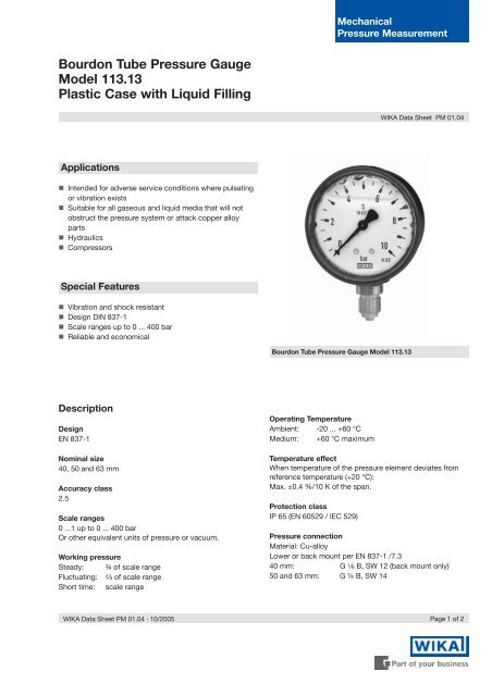
Mechanical<strong>Pressure</strong> Measurement<strong>Bourdon</strong> <strong>Tube</strong> <strong>Pressure</strong> <strong>Gauge</strong><strong>Model</strong> <strong>113.13</strong>Plastic Case with Liquid FillingWIKA Data Sheet PM 01.04Applications! Intended for adverse service conditions where pulsatingor vibration exists! Suitable for all gaseous and liquid media that will notobstruct the pressure system or attack copper alloyparts! Hydraulics! CompressorsSpecial Features! Vibration and shock resistant! Design DIN 837-1! Scale ranges up to 0 ... 400 bar! Reliable and economical<strong>Bourdon</strong> <strong>Tube</strong> <strong>Pressure</strong> <strong>Gauge</strong> <strong>Model</strong> <strong>113.13</strong>DescriptionDesignEN 837-1Nominal size40, 50 and 63 mmAccuracy class2.5Scale ranges0 ...1 up to 0 ... 400 barOr other equivalent units of pressure or vacuum.Working pressureSteady: ¾ of scale rangeFluctuating: B of scale rangeShort time: scale rangeOperating TemperatureAmbient: -20 ... +60 °CMedium: +60 °C maximumTemperature effectWhen temperature of the pressure element deviates fromreference temperature (+20 °C):Max. ±0.4 %/10 K of the span.Protection classIP 65 (EN 60529 / lEC 529)<strong>Pressure</strong> connectionMaterial: Cu-alloyLower or back mount per EN 837-1 /7.340 mm: G E B, SW 12 (back mount only)50 and 63 mm: G ¼ B, SW 14WIKA Data Sheet PM 01.04 · 10/2005Page 1 of 2
<strong>Pressure</strong> elementCu-alloy,≤ 40 bar: C-type> 40 bar: helical typeMovementCu-alloyDialWhite plastic, with pointer stop pin with black letteringPointerBlack plasticDimensionsStandard versionsRadial bottom pressure connection, NS 50, 631034 502CaseNS 40: black plasticNS 50, 63: black plastic, with integral panel ringO-ring seal between case and entry stemRanges ≤ 6 bar with compensating valve to vent caseWindowClear plastic, welded with caseLiquid fillingGlycerine 99,7%Options! NS 40: Case with integral panel ring! NS 50, 63: 3-hole panel mounting flange! Panel mounting clamp (for back connection)Centre back pressure connectionNS 40NS 50, 631034 510 1034 499NS Dimensions in mm Weight in kga b b 1b 2D 1D 2e G h ± 1 SW40 - - 27 42.5 44.5 1) 41 5 1) G B - 12 0.1350 11.5 27 29.5 53 55 51 5 G ¼ B 48 14 0.1763 11.5 27 29.5 53 68 63 5 G ¼ B 54 14 0.21Standard pressure entry with parallel thread and sealing to EN 837-1 / 7.3Ordering information<strong>Pressure</strong> gauge model / Nominal size / Scale range / Size of connection / Optional extras requiredSpecifications and dimensions given in this leaflet represent the state of engineering at the time of printing.Modifications may take place and materials specified may be replaced by others without prior notice.Page 2 of 2WIKA Data Sheet PM 01.04 · 10/20059019669 10/2005 DWIKA Alexander Wiegand GmbH & Co. KGAlexander-Wiegand-Straße 3063911 Klingenberg/GermanyPhone (+49) 93 72/132-0Telefax (+49) 93 72/132-406E-Mail info@wika.dewww.wika.de