Flange Connection, Diaphragm Seals With Flush ... - BKW Instruments
Flange Connection, Diaphragm Seals With Flush ... - BKW Instruments
Flange Connection, Diaphragm Seals With Flush ... - BKW Instruments

Create successful ePaper yourself
Turn your PDF publications into a flip-book with our unique Google optimized e-Paper software.
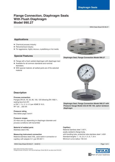
<strong>Diaphragm</strong> <strong>Seals</strong><strong>Flange</strong> <strong>Connection</strong>, <strong>Diaphragm</strong> <strong>Seals</strong><strong>With</strong> <strong>Flush</strong> <strong>Diaphragm</strong>Model 990.27WIKA Data Sheet DS 99.27Applications■■Chemical process industry■■Petrochemical industry■■For aggressive, highly viscous, crystallising or hot mediaSpecial Features<strong>Diaphragm</strong> Seal, <strong>Flange</strong> <strong>Connection</strong> Model 990.27■■<strong>Flange</strong> with a flush welded diaphragm with diaphragm bed■■Available for all common standards and nominaldiameters■■<strong>With</strong> special material, all wetted parts are of the selectedmaterialDescriptionProcess connection<strong>Flange</strong>s DN 25, 40, 50, 80, 100, 125 following EN 1092-1,sealing face form B1or DN 1, 1½, 2, 3, 4, 5 per ASME B 16.5,RF 125 ... 250 AAPressure ratingSee tables page 3 and 4<strong>Diaphragm</strong> Seal, <strong>Flange</strong> <strong>Connection</strong> Model 990.27 withPressure Gauge Model 232.50 NS 100, option tantalumdiaphragmPressure ranges25 mbar and up, depending on diaphragm diameter andprocess conditions with transmitterMaterial of wetted partsStainless steel 316LMeasuring instrument connectionMaterial stainless steel 316L, axial weld-in connection orcapillary with adapter G ½ per EN 837-1CapillaryMaterial stainless steel 1.4571,axially welded to flange body,with handling tube, protective tube stainless steel 1.4301Standard lengths: 1, 1.6, 2.5, 4, 5, 6, 7, 8 mMinimum curve radius: 150 mmWIKA Data Sheet DS 99.27 ∙ 04/2010Page 1 of 4Data sheets showing similar products:<strong>Flange</strong>d process connection, with internal diaphragm; Model 990.26; see data sheet DS 99.26
OptionsExample for installationProcess connection■■Other flanges on request■■Sealing faces per EN 1092-1, form B2 orper ASME B 16.5, RF 125 AA, 500AA, RFSF;EN 1092-1 groove and tongue; projection and recess;ASME B 16.5 snap ring groove form RJF(limited for special materials, on request)■■Flame arrester for connection to Zone 0<strong>Diaphragm</strong> seal, flange connection model 990.27 withpressure gaugePressure measuringinstrument(pressure gauge or transmitter)P4_Z1872.01Measuring instrument connection■■Capillary with welding connection■■Axially welded adapter per EN 837-1■■Various adapters for direct assembled processtransmitters■■Cooling element (direct assembly; for processtemperature > +100 °C)Material of wetted parts■■Process temperature limit 400 °CStainless steel 1.4435, 1.4541, 1.4571, 1.4539,Monel 400, Hastelloy C276, Hastelloy C4, Inconel 600,Inconel 625, Incoloy 825, gold plating (approx. 25 µm),wikaramic coating■■Process temperature limit 300 °CTantalum■■Process temperature limit 260 °CHastelloy B2, Hastelloy C22, nickel, Duplex 1.4462PTFE foil (≤ 100 bar), PFA coatingDirect assemblySystem fill fluid<strong>Diaphragm</strong> seal<strong>Diaphragm</strong>(welded with diaphragm seal)Mating flange 1)Connecting screws 1)Flat gasket 1)1) Not included of delivery■■Process temperature limit 150 °CPlatinum, titanium, zircon, silver foil,ECTFE (Halar) coatingFurther materials and process temperature limits on requestCapillary■■Special lengths between 1 and 15 m■■Protective tube made of flexible PE or PTFE<strong>Flush</strong>ing ring■■Stainless steel 316L, for connection DN 40 ... 125 per ENor NPS 1½ ... 5 per ASME(see data sheet AC 91.05)Page 2 of 4 WIKA Data Sheet DS 99.27 ∙ 04/2010
Dimensions in mmOptionally with adapterG ½ per EN 837-1 /7.3.51387979.02<strong>Flange</strong> connection following EN 1092-1, form B1 / DIN 2501, form DDN Class Dimensions in mm Raised face Weightin mm in bar Mb D b d 2 k f d 4 x in kg25 10/40 32 115 18 14 85 2 68 4 1.563/100 25 140 24 18 100 2 68 4 2.540 10/40 45 150 18 18 110 2 88 4 2.163/100 45 170 26 22 125 2 88 4 4.0160 45 170 28 22 125 2 88 4 4.3250 45 185 34 26 135 2 88 4 6.350 10/40 59 165 20 18 125 2 102 4 3.363 59 180 26 22 135 2 102 4 5.1100 59 195 28 26 145 2 102 4 6.5160 59 195 30 26 145 2 102 4 7.0250 59 200 38 26 150 2 102 8 9.380 10/16 89 200 20 18 160 2 138 8 4.925/40 89 200 24 18 160 2 138 8 5.863 89 215 28 22 170 2 138 8 7.9100 89 230 32 26 180 2 138 8 10.4160 89 230 36 26 180 2 138 8 11.7250 89 255 46 30 200 2 138 8 18.4100 10/16 89 220 20 18 180 2 158 8 5.925/40 89 235 24 22 190 2 162 8 8.163 89 250 30 26 200 2 162 8 11.5100 89 265 36 30 210 2 162 8 15.5160 89 265 40 30 210 2 162 8 17.3250 89 300 54 33 235 2 162 8 29.9125 10/16 124 250 22 18 210 2 188 8 8.425/40 124 270 26 26 220 2 188 8 11.663 124 295 34 30 240 2 188 8 14.7100 124 315 40 33 250 2 188 8 24.4160 124 315 44 33 250 2 188 8 26.9250 124 340 60 33 275 2 188 12 42.7Mb = effective diameter of diaphragm, x = number of drill holesFurther dimensions and higher pressure ratings on requestWIKA Data Sheet DS 99.27 ∙ 04/2010Page 3 of 4
<strong>Flange</strong> connection per ASME B 16.5, raised faceDN Class Dimensions in mm Raised face WeightMb D b d 2 k f d 4 x in kg1" 150 32 110 14.7 16 79.4 2 51 4 1.4300 32 125 17.9 19 88.9 2 51 4 1.71½" 150 45 125 17.9 16 98.4 2 73 4 1.6300 45 155 21.1 22 114.3 2 73 4 2.5600 45 155 29.3 22 114.3 7 73 4 3.31500 45 180 38.8 29 123.8 7 73 4 5.92500 45 205 51.5 32 146 7 73 4 10.42" 150 59 150 19.5 19 120.7 2 92 4 2.7300 59 165 22.7 19 127 2 92 8 3.7600 59 165 32.4 19 127 7 92 8 5.71500 59 215 45.1 26 165.1 7 92 8 13.22500 59 235 57.9 29 171.4 7 92 8 19.83" 150 89 190 24.3 19 152.4 2 127 4 5.3300 89 210 29 22 168.3 2 127 8 7.8600 89 210 38.8 22 168.3 7 127 8 11900 89 240 45.1 26 190.5 7 127 8 16.71500 89 265 54.7 32 203.2 7 127 8 24.52500 89 305 73.7 35 228.6 7 127 8 42.74" 150 89 230 24.3 19 190.5 2 158 8 7.7300 89 255 32.2 22 200 2 158 8 12.7400 89 255 42 26 200 7 158 8 17.4600 89 275 45.1 26 215.9 7 158 8 21.5900 89 290 51.5 32 235 7 158 8 27.71500 89 310 61 35 241.3 7 158 8 372500 89 355 83.2 42 273 7 158 8 65.7Mb = effective diameter of diaphragm, x = number of drill holesFurther dimensions and higher pressure ratings on requestOrdering informationModel / Process connection (standard, nominal size, pressure rating, sealing face) / Material (wetted parts) / Instrumentconnection: direct assembly or via capillary, capillary length / System fill fluid / Assembly with pressure measuring instrument... / Process conditions: application, max. and min. process temperature, max. and min. ambient temperatureThe specifications given in this document represent the state of engineering at the time of publishing.We reserve the right to make modifications to the specifications and materials.Page 4 of 4 WIKA Data Sheet DS 99.27 ∙ 04/201004/2010 GBWIKA Alexander Wiegand SE & Co. KGAlexander-Wiegand-Straße 3063911 Klingenberg/GermanyTel. (+49) 9372/132-0Fax (+49) 9372/132-406E-mail info@wika.dewww.wika.de