Download you PDF version! - Sontay
Download you PDF version! - Sontay
Download you PDF version! - Sontay

Create successful ePaper yourself
Turn your PDF publications into a flip-book with our unique Google optimized e-Paper software.
SONTAY'S Sales Management TeamOur team will be pleased to hear from <strong>you</strong> whenever <strong>you</strong> require any information on our range of products and services.Customer Services Team+44 (0)1732 861200UK fax +44 (0)1732 861201International telephone +44 (0)1732 861225Emailsales@sontay.comWebsitewww.sontay.comAlan BraybrookSales & Marketing DirectorTelephone: +44 (0)1274 412455Fax: +44 (0)1274 414956Email: alan.braybrook@sontay.comStacey LucasCommercial ManagerTelephone: +44 (0)1732 861216Fax: +44 (0)1732 861217Email: stacey.lucas@sontay.comGary BartlettUK and Ireland Sales ManagerTelephone: +44 (0)7966 814472Fax: +44 (0)1732 861221Email: gary.bartlett@sontay.comKerima CassimInternational Sales ManagerTelephone: +44 (0)1732 861214Fax: +44 (0)1732 861215Email: kerima.cassim@sontay.comJohn CameronMiddle East Sales ManagerMiddle East Technical Sales OfficePO Box 121760, Dubai, UAETelephone: +971 4 359 8106Fax: +971 4 359 8107Email: john.cameron@sontay.meWeb: www.sontay.me6www.sontay.com · Email sales@sontay.com
Measure the speed and volume of air and liquid with ourair and water flow products. Applications include sensingof air velocity in ducts, wind speed and direction outside,monitoring of air and liquid in ducts and pipes and levelsof liquids and other mediums in tanks.Control air quality for comfort and vitality using ourair quality and CO 2 sensing equipment. Use our gas leakalarm system to provide safety alarms and shutdownfacilities on commercial and industrial gas installations.Our range of controllers offer many benefits throughintelligently controlling heating and ventilation systems.This facilitates not only the comfort of the occupant but alsosavings in energy, reducing costs and carbon footprint.IO modules offer capability for rescaling, converting,isolating and overriding signals from BMS controllers.Metering is a major requirement through EU legislationin new building and refurbishments. <strong>Sontay</strong> offer a fullrange of water, heat, gas and energy meters as wellas expert technical advice for <strong>you</strong>r application.The peripherals and interfaces group is full of productsthat will give <strong>you</strong> greater monitoring and control inany application. From emergency switches to waterleak detection to give early warning and shutdown inemergency situations to light level and occupancy sensorswhich can be used for security and energy savings.There are also bespoke user interface solutions for thoseprojects that require a more specific solution.The pressure range consists of switches and sensors for airand liquid. They offer monitoring and indication of flow inHVAC applications to ensure systems are working correctly.Our temperature and RH sensors are renownedfor their accuracy and reliability and are availablefor a variety of applications. We have recentlyintroduced new housings for all of our temperatureand RH sensors and thermostats. These sensors matchseamlessly together and provide a uniform look.SonNet, our wireless range offers the same accuracyand reliability but with the added cost savings ofa wireless system and now has a network serial driverfor integration with the Niagara Framework TM.A range of valves, actuators and solenoid valves forthe control of water and gas. Our (VT) terminal and(VE) plug and seat valves have the added security of alifetime warranty on the castings as well as a 5 year or 1.5million cycle warranty on the serviceable and replaceablecartridges. We sell many actuator options to suit <strong>you</strong>rapplication including damper and thermic actuators withraise/lower and modulating control. Our gas solenoidvalves are available in manual or auto reset and nowhave the added option of an end switch.ContentPageAir & Water FlowAV Air Velocity Sensors & Probes 8-9FS Air & Liquid Flow Switches 12LS Liquid Level Switches & Sensors 24Air Quality & Gas DetectionGL Gas Leak Alarm Systems 12GS Air Quality, Carbon Dioxide/RH & T & Gas Sensors 13-17SD Duct Smoke Detector 51ControllersCN Temp. Controller 9FC Fan Speed Controllers 10-11RE Electric Heater Battery Controllers 41Input/Output ModulesIO Input / Output Modules 18-20MeteringMW Water Meters, Integrators & Flow Sensors 30MG Gas Metering 24PM Energy Analysers & Power Monitoring 38-40Peripherals & InterfacesEP Emergency Switches/Buttons & Thermal Link 9-10LL Light Level Controllers & Sensors 21LN LonWorks FTT Network Repeater & Terminator 22OC Occupancy Detectors 30PS Power Output Supplies 40UI User Interfaces & Alarm Annunciators 62WD Water Detection System & Sensors 70-71PressurePA Air DP Sensors & Switches 31-33PL Liquid Pressure Sensors & Switches 34-37Relative HumidityRH RH & T Sensors & Humidistats 49-50Wireless DevicesRF Sensors, Routers & Site Survey Kit 42-48TemperatureST Temperature Thermostats 51-52TT Temperature Sensors & Pockets 53-61Valves & ActuatorsVA Damper, Valve & Failsafe Actuators 63VE Plug & Seat Valve Assemblies 64-65VR Rotary Shoe Valves 66VS Gas Safety & Solenoid Valves 69-70VT Terminal / Fan Coil Valves & Actuators 67-68VZ Zone Valves & Actuators 68Thermistor Types and Compatibility Charts 72-75General Information and Terms & Conditions of Sale 76-81<strong>Sontay</strong> Account Application Form 82<strong>Sontay</strong> Return Procedure 83Product Name Listing (in alphabetical order) 84-86UK Tel. +44 (0) 1732 861200 · Int. Tel. +44 (0) 1732 861225 · UK Fax +44 (0) 1732 861201 · Int. Fax +44 (0) 1732 8612267
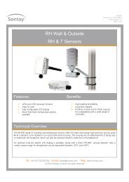
Air Velocity Probes & SensorsAir velocity measurement isan important factor in thecontrol of ventilation systemsto ensure that recommendedflow rates are achieved.AV-EP multi-point sensorscan be used to ensure thatoptimum sensing is achieved.Use AV-MPS multi-point sensors in pairsdepending on size of duct:600-700mm (23.62-27.56”) · AV-MPS700700-800mm (27.56-31.50”) · AV-MPS800750-1000mm (31.50-39.37”) · AV-MPS10001000-1250mm (39.37-49.21”) · AV-MPS12501250-1500mm (49.21-59.06”) · AV-MPS15001500-1750mm (59.06-68.90”) · AV-MPS17501750-2000mm (68.90-78.74”) · AV-MPS2000AV-DSPSingle-point Air Velocity SensorThe AV-DSP is a single-point, multi-rangeAir Velocity Transmitter with user selectable0-10Vdc or 4-20mA outputs and four userselectable measurement ranges. The unit hasa built-in self-test feature and the user canmanually override the output to 0%, 50% or100% of output range to aid commissioning.FEATURES■■User selectable 0-10Vdc or 4-20mA outputs■■Built-in self-test feature■■Built-in manual override facility for 0%, 50% or 100% of output range■■Durability and resistance to chemical reagentsPart codeAV-DSPDPAData sheet: AV-DSP.pdfDescriptionAir Velocity SensorAccessoryDuct probe adjustment flangeSPECIFICATIONSelectable ranges:Accuracy:Output:Supply (current output):Supply (voltage output):0 to 4 m/s, 0 to 8 m/s, 0 to 16 m/s, 0 to 32 m/s,0 to 787 ft/min, 0 to 1575 ft/min, 0 to 3150 ft/min,0 to 6299 ft/min±3% of ranges4-20mA, 100Ω loop resistance min.0-10Vdc into 4.7kΩ min.20 to 35Vdc for 500Ω loop resistance12 to 30Vdc for 100Ω loop resistance17 to 34Vdc14 to 26Vac supply into 4.7kΩ min.50mA–10 to +50°C (14 to 122°F)Max. current:Ambient temp. range:Housing: Material Flame retardant ABSDimensions 55 x 90mm dia. (2.17 x 3.54” dia.)Probe: Material DelrinDimensions 215 x 19mm dia. (8.46 x 0.75” dia.)Protection:Weight:IP65280g (0.62 lb)AV-WWind Speed and Direction SensorsThe AV-WS measures wind speed providing apulsed output and is intended for applicationswhere external weather conditions influencethe building control strategy, such as for theautomatic closing of windows. A mounting armand ‘U’ bolts for pole mounting are included.SPECIFICATION – AV-WSOutput:1 contact closure per 1.493 metre (4.90 ft) (zero bounce)Min. start speed: 0.5 m/s (98 ft/min)Accuracy: ±2%Contact rating: Power 50W max. (DC resistive)Voltage 100Vdc max.Current 1A max.Weight:1.46kg (3.22 lb)COMMON SPECIFICATIONElectrical conns:Flying lead (3m long) (9.48 ft)Ambient range:–20 to +70°C (–4 to +158°F)Dimensions: Height 280mm (11.02”) (max. arc 120mm) (4.72”)Protection:IP65SPECIFICATION – AV-WADMechanical travel: 360° endless travelElectrical travel: 357° (±2°)Output:0 to 1kΩ for 0 to 357° @ 80Vdc max.Weight:1.56kg (3.44 lb)Part codeAV-WSAV-WADData sheet: AV-W.pdfDescriptionWind Speed SensorWind Speed and Direction SensorAir & Water Flow Air Quality & Gas Detection Controllers Input / Output Modules Water & Energy Metering Peripherals8www.sontay.com · Email sales@sontay.com
AV-XMulti-point Air Velocity ProbesThe AV-EP series of air velocity probes areavailable in lengths from 100 to 600mm (3.94 to23.62”) and the AV-MPS series in lengths of 700to 2000mm (27.56 to 78.74”). They are used toensure that recommended flow rates for publicbuildings and industrial plant are achieved. It isalso useful to measure the carrying velocities fordust extraction, where the recommended flowrate will depend on the material being exhaustedin the extract system.Using a PA-500, PA-267 or PA-699 Air Differential Pressure Sensor of anappropriate range (please refer to data sheet on <strong>Sontay</strong>’s website for furtherinformation), the output of the sensor represents the velocity pressure and isdefined by the following equation:Velocity = (2 x Velocity Pressure) / 1.2Part code DescriptionAV-EP100 100mm (3.94”) Multi-point Probe (ABS)AV-EP200 200mm (7.87”) ”AV-EP300 300mm (11.81”) ”AV-EP400 400mm (15.71”) ”AV-EP500 500mm (19.69”) ”AV-EP600 600mm (23.62”) ”FEATURES■■Mounting plates included■■Double gasket seals the probe to the duct■■Push on connectors to suit PA-TUBE-8MMSPECIFICATIONProbe Material: AV-EP PVC Flame retardant (VO)AV-MPS 316 Stainless steelConnectors: Nickel plated brass to suit 6mm ID PVC tubingPart code DescriptionAV-MPS700 To suit duct size of 600-700mm (23.62-27.56”)AV-MPS800 ” 700-800mm (27.56-31.50”)AV-MPS1000 ” 750-1000mm (31.50-39.37”)AV-MPS1250 ” 1000-1250mm (39.37-49.21”)AV-MPS1500 ” 1250-1500mm (49.21-59.06”)AV-MPS1750 ” 1500-1750mm (59.06-68.90”)AV-MPS2000 ” 1750-2000mm (68.90-78.74”)AccessoryPA-TUBE-8MM PVC tube 8mm (0.31”) o/d x 1.5mm (0.06”) wall, 30m (98.5 ft)Data sheets: AV-EP.pdf ∙ AV-MPS.pdfCN-DPProportional Temperature ControllerThis controller provides accurate and costeffective proportional control of heatingand cooling loads, AHU and fan coil unitapplications, and underfloor heating control.The controller has an integral LCD display andpush-buttons for easy parameter adjustmentand features both frost and low-limit supplycapabilities. Panel facia and DIN-rail mount caseoptions are available.FEATURES■■Easy installation and set up using integral keypad and LCD■■LED indication of plant status■■Panel fascia or DIN-rail mount case options■■Two 0-10Vdc modulating outputs■■Temperature display in either °C or °F■■Non-volatile memory retains parameters when power is removed■■Fully compatible with <strong>Sontay</strong> A sensors (10K3A1) and remoteset-point unitsSPECIFICATIONDisplay:2 line, 8 character, 0.1°C resolutionLED indicators: Red heatingGreen coolingSetpoint range: 10 to 100°C (50 to 212°F) in 0.5°C (1°F) stepsOutputs:Two 0-10Vdc proportional @ 10mAAmbient range: 0 to 40°C, (32 to 104°F), 0 to 80% RH non-condensingPower supply: 24Vac/dc ±10%Dimensions: 145 x 85 x 23mm (max) (5.71 x 3.35 x 0.91”)Weight:170gPart codeCN-DP200-DINCN-DP200-FPData sheet: CN-DP200.pdfDescriptionTemp. Controller – DIN-rail mountingTemp. Controller – front panel mountingEP-FSFireman’s SwitchesThis range of Safety Switches in lower case isfor use in the event of fire or other emergency.Usually located at exits to gas plant rooms, unitsare key operated with a 2 or 3-position latchingswitch.The EP-KG is a wall or panel-mountedKeyguard. The window is a non-hazardous clearplastic with side tabs designed to break in orderto gain access to the key.It is ideal for use in situations where a glasswindow would pose a hazard, i.e. foodpreparation areas, schools etc.SPECIFICATIONSwitch rating: EP-FS 6A @ 240VacKeys: EP-FS 2 supplied (removable in all positions)Connections: EP-FS 4 x 100mm (3.94”) flying leadsDimensions: EP-FS 86 x 86 x 50mm (3.39 x 3.39 x 1.97”)EP-KG 142 x 125 x 45mm (5.59 x 4.92 x 1.77”)Weight: EP-FS 200g (0.44 lb)EP-KG 220g (0.49 lb)Housing:ABS plasticPart codeEP-FS1EP-FS2EP-FSCEP-KG1EP-KGWDescriptionFireman’s Switch – Red 2-positionFireman’s Switch – Red 3-positionFireman’s Switch – Hinged coverKeyguard – RedKeyguard – Spare windowData sheets: EP-FS.pdf ∙ EP-KG.pdf& Interfaces Pressure Relative Humidity Wireless Devices Temperature Valves & ActuatorsUK Tel. +44 (0) 1732 861200 · Int. Tel. +44 (0) 1732 861225 · UK Fax +44 (0) 1732 861201 · Int. Fax +44 (0) 1732 8612269
EP-SWEP-KLEP-SW10Emergency StopA range of emergency stop buttons for manualshutdown of systems in the event of fire orother emergency.TYPESEP-KLEmergency Stop Button with keylock re-set. Set of 2 keys provided.EP-SW10Emergency Stop Buttonwith recessed re-set button.EP-SW11Emergency Stop Buttonwith twist knob re-set.SPECIFICATIONSwitch rating: EP-KL 15 to 415Vac, 4A13 to 110Vdc, 0.5AOthers 6A @ 240VacReset type: EP-KL KeyEP-SW10 Push (recessed)EP-SW11 TwistDimensions: EP-KL 65 x 65 x 90mm (2.56 x 2.56 x 3.54”)EP-SW10 73 x 80 x 50mm (2.87 x 3.15 x 1.97”)EP-SW11 65 x 65 x 90mm (2.56 x 2.56 x 3.54”)Weight:220g (0.49 lb)Part codeEP-KLEP-SW10EP-SW11Data sheet: EP-ES.pdfDescriptionStop Button – Key lockStop Button – Push button (recessed)Stop Button – Twist knobEP-SW11EP-SW72Fusible Thermal LinkThe EP-SW72 is for use in gas safety circuits.Units consist of a ventilated high temperatureglass filled resin case, with electrical connectionterminals and a thermal fuse. When locatedabove boilers, the fuse activates on detection ofover-temperature to close down the gas system.Replacement fuses are available.SPECIFICATIONHousing:High temperature flame retardent glass filled resinEntry:M20 thread for standard conduitMelting point: 72°C (162°F)Rating:250Vac @ 5AProtection: IP20Dimensions: 85 x 28 x 65mm (3.35 x 1.10 x 2.56”)Weight:60gPart codeEP-SW72EP-SW72-FDescriptionElectro-thermal LinkElectro-thermal Link – spare fuseVolume Price Breaks are applicableUnit Price (10-19 and 20+)EP-SW72Please see price listData sheet: EP-SW72.pdfFC-DINFan Speed Controllers (DIN-rail)The FC-DIN range of DIN-rail mounting FanSpeed Controllers offer user selectable 0-10Vdc,4-20mA input control signal compatibilityfor automatic control, and a optional 3-wirepotentiometer input for manual control.The FC-DIN are available in 1A, 3A and 5Asingle phase ratings. A fast start function isavailable, as well as user definable minimumand maximum run speeds.FEATURES■■User definable maximumand minimum speed■■Fast on normal start up■■User definable fast start timeAPPLICATIONFan or pump speed control, for energy and costsavings.SPECIFICATIONSupply: 230Vac, –6%, +10%Frequency: 7 to 64HzInputs:4-20mA (not loop powered)0-10Vdc0-10kΩ optional 3-wire potentiometerOutput:Triac, phase angleMounting: DIN-railAmbient Range: –10 to +50°C (14 to 122°F)5 to 95% RH non-condensingDimensions: 125 x 75 x 80mm (4.92 x 2.95 x 3.15”)Weight:350g (0.77 lb)Part codeFC-DIN1FC-DIN3FC-DIN5FC-SPData sheet: FC-DIN.pdfDescription1A, 230V, 1-phase Manual Controller3A, 230V, 1-phase Manual Controller5A, 230V, 1-phase Manual ControllerAccessoryManual control adjustmentAir & Water Flow Air Quality & Gas Detection Controllers Input / Output Modules Water & Energy Metering Peripherals10www.sontay.com · Email sales@sontay.com
FC-ERVFan Speed ControllersPart codeFC-ERV1FC-ERV3FC-ERV5FC-ERV10Data sheet: FC-ERV.pdfThe FC-ERV can control the speed of singlephase,voltage controllable electric motors,with a 0-10Vdc or 4-20mA control signal.Centrifugal fans, axial fans, propeller fans andcentrifugal pumps are prime candidates forelectronic speed control.Description1A, 230V, 1-phase Controller3A, 230V, 1-phase Controller5A, 230V, 1-phase Controller10A, 230V, 1-phase ControllerSPECIFICATIONNominal supply: 230Vac, 1-phase, 50-60HzControl type: Automatic from remote signalOn/off switch: Mounted on sideRemote signal: Two wire 4-20mA or 0-10VdcStarting speed: According to signal valueMinimum speed: Adjustable via trim pot.Current ratings: FC-ERV1 - 0.1 to 1.5AFC-ERV3 - 0.1 to 3.0AFC-ERV5 - 0.5 to 5.0AFC-ERV10 - 0.5 to 10.0AFuse:20mm ‘FF’ typeFuse ratings:FC-ERV1 - FF 3AFC-ERV3 - FF 5AFC-ERV5 - FF 10AFC-ERV10 - FF 16AMounting style: Wall mountProtection:IP54Dimensions includingcable gland: 178 x 113 x 92mm (7.01 x 4.45 x 3.62”)Weight:810g max. (1.79 lb)FC-MTYManual Speed Controllers for small motorsPart codeFC-MTY1FC-MTY2FC-MTY4Data sheet: FC-MTY.pdfManual control for small, single-phase motorsup to 4 amps. Suitable for wall and/or flushmounting.Description1A, 230V, 1-phase Controller2A, 230V, 1-phase Controller4A, 230V, 1-phase ControllerSPECIFICATIONNominal supply: 230Vac, 1-phase, 50-60HzControl type: Manual via potentiometerOn/off switch: Inbuilt with pot.Pot. action:Clockwise = min. to max. speedMinimum speed: Adjustable via trim potCurrent ratings: FC-MTY1 - 0.1 to 1.0AFC-MTY2 - 0.2 to 2.0AFC-MTY4 - 0.4 to 4.0AFuse:20mm ‘FF’ typeFuse ratings: FC-MTY1 - FF 1.25AFC-MTY2 - FF 2.5AFC-MTY4 - FF 5AMounting style: Wall and flush mount (FC-MTY4 wall mount only)Protection:FC-MTY1, MTY2 IP44FC-MTY4 IP54Dimensions: Wall mount 82 x 82 x 65mm (3.23 x 3.23 x 2.56”)Flush mount: 82 x 82 x 56mm (3.23 x 3.23 x 2.20”)Weight:360g max. (0.79 lb)FC-STLManual Speed ControllersPart codeFC-STL3DFC-STL5DFC-STL10DData sheet: FC-STL.pdfThis range of manual speed controllers providesingle-phase voltage control for AC motors, byvarying the supplied voltage through phaseanglecontrol.Description3A, type D, 1-phase Controller5A, type D, 1-phase Controller10A, type D, 1-phase ControllerSPECIFICATIONNominal supply: 230Vac, 1-phase, 50-60HzOn/off switch: Separate to potentiometer, mounted on sideStarting sequence: Full speed for 6 to 7 secsPot. action:Clockwise = max. to min. speedMinimum speed: Adjustable via trim pot.Current ratings: FC-STL3D - 0.3 to 3.0A, FC-STL5D - 0.2 to 5.0AFC-STL10D - 0.5 to 10.0AFuse:20mm ‘FF’ typeFuse ratings:FC-STL3D - FF 5AFC-STL5D - FF 8AFC-STL10D - FF 16AMounting style: Wall mountProtection:IP54Dimensions including FC-STL3D 160 x 83 x 66mm (6.30 x 3.27 x 2.60”)cable gland: FC-STL5D 160 x 83 x 81mm (6.30 x 3.27 x 3.19”)FC-STL10D 178 x 113 x 102mm (7.01 x 4.45 x 4.02”)Weight:740g max. (1.63 lb)& Interfaces Pressure Relative Humidity Wireless Devices Temperature Valves & ActuatorsUK Tel. +44 (0) 1732 861200 · Int. Tel. +44 (0) 1732 861225 · UK Fax +44 (0) 1732 861201 · Int. Fax +44 (0) 1732 86122611
FS-521Air Flow SwitchThe FS-521 paddle switch is intended to monitorair flow within a duct and provides a switchedoutput on detection of either a specific airvelocity or flow failure.FEATURES■■Adjustable switching point■■Lid-mounting screws providetamper proofingSPECIFICATIONOperating temp: Ambient –20 to +70°C (–4 to +158°F) max.Media –20 to +120°C (–4 to +248°F) max.Materials: Paddle Stainless steelRod BrassEnclosure ABS flame retardant (type VO)Switch rating: 15(8)A SPDT @ 230VacProtection:IP65Dimensions: Paddle 80 x 175mm, (3.15 x 6.89”)Housing 113.5 x 65 x 62mm (4.47 x 2.56 x 2.44”)Weight:300g (0.66 lb)Part codeFS-521Description80 x 175mm (3.15 x 6.89”) Paddle SwitchVolume Price Breaks are applicableUnit Prices (5+)FS-521Please see price listData sheet: FS-521.pdfFS-541Liquid Flow SwitchesThe FS-541 series of paddle switches areintended to monitor liquid flow within pipesand provides a VFC output on detection ofeither a specific flow rate or flow failure.They screw directly into a 1” BSPT boss.FEATURES■■Adjustable switching point■■Stainless steel wetted parts for aggressivemedia (FS-541S)SPECIFICATIONOperating temp: –40 to +120°C (–40 to +248°F) (max.)Materials: Paddle Stainless steelRod Brass (S/S for FS-541S)Enclosure ABS flame retardantSwitch rating: 15(8)A SPDT @ 24-250Vac, VFCPipe suitability: 1” to 8”Protection:IP65Dimensions: Housing 113.5 x 65 x 62mm (4.47 x 2.56 x 2.44”)Paddles 28.5, 54.5, 83.5 and 161.5mm(1.12, 2.15, 3.29 and 6.36”)Weight:300g (0.66 lb)Part codeFS-541FS-541SDescription1” BSPT Flow Switch1” BSPT Flow Switch (stainless steel paddle)Volume Price Breaks are applicableUnit Prices (5+)FS-541Please see price listData sheet: FS-541.pdfGL-COGas Leak Alarm SystemsA range of stand-alone gas leak alarmSystems for use in commercial / industrialgas installations to provide safety alarm andshutdown facilities on detection of gas leakage.FEATURES■■1, 2 & 3 channel options■ ■ Audio and visual alarms■ ■ Adjustable alarm sensitivity■ ■ Relay output for gas shut-off valves■ ■ Relay output for remote alarms■ ■ Auto or manual reset selectable■ ■ Self-diagnosis fault systemSPECIFICATIONPower supply: 230Vac ±10% @ 50/60Hz or 12V ±10%Relay output(s): GL-CO-RFG361 SPDT, 250V @ 5(1)AGL-CO-RFG65x 2 x SPDT, 250V @ 5(1)AMaterials: Base NylonCoverABSAmbient: Storage temp. –25 to +60°C (–13 to +140°F)Operating temp. 0 to 45°C (32 to 113°F)Relative humidity Class F DIN 40040Protection:IP40Weight: GL-CO-RFG361 250g (0.55 lb)GL-CO-RFG65x 600g (1.32 lb)SENSOR TYPESNatural Gas Sensor: GL-CO-SRS150Propane Sensor:GL-CO-SRS250Carbon Monoxide Sensor: GL-CO-SRS350Part code DescriptionControllers (DIN-rail mount)GL-CO-RFG361 1-channel, 1 x SPDTGL-CO-RFG651 1-channel, 2 x SPDTGL-CO-RFG652 2-channel, 2 x SPDTGL-CO-RFG653 3-channel, 2 x SPDTOptionsGL-CO-RFG-FMK3 Panel door mounting kit for RFG361GL-CO-RFG-FMK6 Panel door mounting kit for RFG65xGL-CO-RFG-WMK6 Wall mounting kit for RFG65xSensorsGL-CO-SRS150 Combustibles Sensor (natural gas)GL-CO-SRS250 Propane/LPG SensorGL-CO-SRS350 Carbon Monoxide SensorData sheets: GL-CO-RFG361.pdf ∙ GL-CO-RFG65x.pdfAir & Water Flow Air Quality & Gas Detection Controllers Input / Output Modules Water & Energy Metering Peripherals12www.sontay.com · Email sales@sontay.com
Air Quality & Gas Sensing<strong>Sontay</strong> offer a wide range of air sensing productsControl of air quality and gases inpopulated areas is essential for notonly comfort but health purposes.Our range of sensors offeraccurate measurement of airquality, CO ²and CO so thatadequate ventilation canbe introduced when thepreset limits are exceeded.Wall types with optional LCD screensand duct models are available.LCD screen options are available.OptimumCO ²levelCO ²levelsrisingVentilationrequiredGS-AQ1000Space Air Quality SensorThe <strong>Sontay</strong> GS-AQ1000 series of volatileorganic compound (VOC) sensors are setin our aesthetically pleasing (1000) spacehousing. Based on tried and tested SnO ²sensortechnology, the new design provides a highlycost-effective answer for monitoring VOCs forindoor air quality, typically for alarm purposes.The sensor element responds to a broad rangeof contaminants, such as Ammonia (NH ³) andHydrogen Sulphide (H ²S), generated from wastematerials in office and home environments.It also has high sensitivity to low concentrationsof VOCs such as toluene emitted from woodfinishing and construction products.FEATURES■■Designed to be aesthetically pleasing■■Blends into the fabric of any building■■Developed using customer feedbackand involvement■■Fully configurable LCD display option.Please contact the Customer ServiceTeam for more information.Specification:Active Outputs: Voltage 0-10Vdc or 0-5VdcCurrent 4-20mAOptional Passive Outputs: Thermistor Any <strong>Sontay</strong> thermistor type*Setpoint 11-1kΩ/0-10kΩ, linearOverride VFCFan Speed 3 position Resistive5 position ResistivePower Supply: 0-10Vdc 12 - 26Vac or 16 - 26Vdc4-20mA 20 - 26Vdc onlyAmbient: Temperature 0 to 50°C (32 to 122°F)RH0 to 95% RH, non-condensingHousing material: ABS (flame retardant)Dimensions: 115 x 85 x 28mm (4.53 x 3.35 x 1.10”)Weight:180g (0.40 lb)* Notes:1. -T <strong>version</strong> uses a thermistor element for direct measurement oftemperature. Please specify thermistor type when ordering.2. When using the -T option, they are not compensated for internal heating.3. Please see page 72 for Thermistor Types and Compatibility Chart.Part code DescriptionGS-AQ1000 Space Air Quality TransmitterSuffixes (add to part code)-T Direct resistive temperature output **-SP2-wire, 11-1kΩ/0-10kΩ setpoint-MSMomentary switch-FS33-speed fan switch** When using -T option there is no compensation for internalheating. Please allow for this in temperature scaling.Part code DescriptionSuffixes (add to part code)-FS55-speed fan switch-LCDIntegral LCD display-TRCustom temperature output range-ACTActive Output-TemperatureAccessoryGASKET Insulating gasket (pack of 10)Data sheet: GS-AQ1000.pdf& Interfaces Pressure Relative Humidity Wireless Devices Temperature Valves & ActuatorsUK Tel. +44 (0) 1732 861200 · Int. Tel. +44 (0) 1732 861225 · UK Fax +44 (0) 1732 861201 · Int. Fax +44 (0) 1732 86122613
GS-AQ521Duct Air Quality SensorDuct air quality transmitter is designed for usein the optimisation of the quantity of freshair introduced into a building for ventilationpurposes. The sensors are sensitive to a rangeof odours, smoke, solvent gases etc., andprovide an output proportional to the mixedgas concentration.This signal can be used to control fresh air fansand dampers according to the ventilation load.In installations where the primary contaminantload is human respiration, it is recommendedthat a CO ²transmitter is used.FEATURE■ Detects particulates as well as gasesSPECIFICATIONSensor type:Tin dioxide filmAmbient range: Temperature 0 to 50°C (32 to 122°F)RH 0 to 100%Power supply: 24Vac/dc ±10%Output:0 to 10VdcMaterial: Housing Flame retard ABSProbe PVCProtection:IP65Dimensions: Housing 57 x 85mm dia. (2.24 x 3.35” dia.)Probe 200 x 25mm (7.87 X 0.98”)Weight:300g (0.66 lb)Part codeGS-AQ521DPAData sheet: GS-AQ521.pdfDescriptionDuct Air Quality TransmitterAccessoryDuct probe adjustment flangeGS-CO2-1000Carbon Dioxide, RH & T SensorsThe new <strong>Sontay</strong> GS-CO2-1000 range ofcombined CO ², Temperature and RH sensors areset in our aesthetically pleasing (1000) spacesensor housing.Using a non-dispersive infrared sensor formeasuring CO ²concentrations and utilisingmicroprocessor based electronics, the uniqueself-calibration algorithm offers long-termstability and accuracy. They are also fittedwith a temperature output or RH output. Adirectly connected passive resistive temperatureoutput is also available, as an alternative to thestandard active temperature output.The sensor can be used to ensure adequateventilation while maximising energy savings byventilating at the optimum level, making theseideal for all types of ventilation in commercialbuildings, industrial plants, laboratories andpublic spaces, such as schools.FEATURES■ CO ²Self-calibration algorithm■ 0-10Vdc or 4-20mA outputs, with ModBus as standard■ Up to two analogue outputs■ Designed to be aesthetically pleasing■ Blends into the fabric of any buildingSPECIFICATIONOutputs:0-10Vdc, 4-20mA (3-wire) or ModBusPower supply:24Vac/dcSupply current:50mA maximum, 32mA averageMeasurement ranges: CO ²0 to 2000ppmTemperature 0 to 50°C (32 to 122°F)RH 0 to 100%Optional passive output: PTC/NTC Element Any <strong>Sontay</strong> resistive type*ModBus:19200bps, 15kV antistatic protectionSensor life:10 years typicalAccuracy: CO ²±40ppm +3% of readingTemperature ±0.5°C (0.9°F)RH ±3%RH (20 to 80%)Stability: CO ²
GS-CO2-RHTGS-CO2-RHT-D typesGS-CO2-RHT-W-LCD typesCarbon Dioxide, RH & T SensorsUsing a non-dispersive infrared sensor formeasuring CO ²concentrations and utilisingmicroprocessor based electronics, the uniqueself-calibration algorithm offers long-termstability and accuracy. They are also fitted witha RH and temperature output, and have an LCDwith 3-colour ‘traffic light’ status indication.The sensor can be used to ensure adequateventilation while maximising energy savings byventilating at the optimum level, making theseideal for all types of ventilation in commercialbuildings, industrial plants, laboratories andpublic spaces, such as schools.FEATURES■■Real-time detecting CO ²levels■■Self-calibration algorithm■■User selectable outputs with ModBus option■■3-colour ‘traffic light’ LCD status forCO ²levelsSPECIFICATIONOutput:4-20mA, 0-10Vdc (jumper selectable) or ModBusModBus RS485: 19200bps, 15kV antistatic protectionPower supply: 4-20mA 24Vdc ±10%0-10Vdc 24Vac/dc ±10%Max. current: 146mASensor life: 15 years (-D types), 10 years (-W types), typicalDuct air velocity: 0 to 450m/min (0 to 1476 ft/min) (-D types only)Accuracy: CO ²±40ppm +3% of reading @ 22°C (72°F)RH< ±3% @ 25°C (77°F)Temperature ±0.4°C (-D types), ±0.5°C (-W types)Stability: CO ²±40ppm +3% of reading @ 22°C (72°F)RH< ±3% @ 25°C (77°F)Temperature ±0.4°C (-D types), ±0.5°C (-W types)LCD indication: 3-colour, indicating CO ², RH & Temp. levelsGreen optimal (1400ppm)Ambient range: Temperature 0 to 50°C (32 to 122°F)RH0 to 95% non-condensingHousing material: Flame retardant ABSDimensions: Duct types Housing 100 x 80 x 50mm(3.94 x 3.15 x 1.97”)Probe 125.5 x 40mm(4.94 x 1.57”)Wall types Housing 130 x 85 x 36.5mm5.12 x 3.35 x 1.44”)Protection: Duct types IP54Wall types IP30Weight: Duct types 360g (0.79 lb)Wall types 260g (0.57 lb)Part codeDescriptionWall Mounting SensorsGS-CO2-RHT-W-LCD CO ²/ RH / T Sensor with LCD DisplayGS-CO2-RHT-W-M-LCD CO ²/ RH / T Sensor with ModBus Output and LCDDisplayData sheet: GS-CO2-RHT-W.pdfPart codeDescriptionDuct Mounting SensorsGS-CO2-RHT-D-LCD CO ²/ RH / T Sensor with LCD displayGS-CO2-RHT-D-M-LCD CO ²/ RH / T Sensor with ModBus Output and LCDDisplayData sheet: GS-CO2-RHT-D.pdfGS-SGas SensorsThe GS-S range of 4-20mA loop powered gassensors are fitted into a robust housing, todetect the following gases:■■Nitrogen dioxide (NO ²)■■Oxygen (O ²)■■Sulphur dioxide (SO ²)FEATURES■■4-20mA output■■Wide supply voltage range (7.5 to 35Vdc)■■Excellent long term stability■■Accuracy unaffected by positionSPECIFICATIONTemp. range:RH range:Output:Supply:Output impedance:Housing material:Protection:Dimensions:Weight:–30 to +50°C (–22 to +122˚F)15 to 90% non-condensing4-20mA7.5 to 35Vdc825ΩABS (flame retardant)IP65 (housing only, suitable for internal mounting only)95 x 90mm dia. (3.74 x 3.54” dia.)160g (0.35 lb)Part code Range ResolutionNO ²– Nitrogen Dioxide SensorsGS-S-ND10 0 to 10ppm 0.1ppmO ²– Oxygen SensorGS-S-OX25 15 to 25% 0.1%Data sheet: GS-S-x.pdfPart code Range ResolutionSO ²– Sulphur Dioxide SensorGS-S-SD20 0 to 20ppm 0.5ppmData sheet: GS-S-x.pdfNote: These units are not intended for use in life safety applications.Air & Water Flow Air Quality & Gas Detection Controllers Input / Output Modules Water & Energy Metering Peripherals16www.sontay.com · Email sales@sontay.com
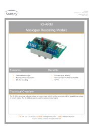
IO Modules<strong>Sontay</strong> offer a wide range of input/output modulesI/O Modules are an integralproduct range in <strong>Sontay</strong>’s portfolioand provide a flexible and costeffective means to expand theinput and output functionalityof any BMS controller.Renowned for their quality andreliability, they incorporate addedfeatures that make them easier toinstall and commission.IO-ABM4Analogue Override ModuleIntended for applications which requireindependent manual override of analogueoutput channels from a BMS controller, as afail-safe in the event of controller failure.Enables actuators to be manually overriddenfrom the panel where local access is difficult.Also useful for commissioning or temporarycontrol of plant prior to controller installation.FEATURES■■4 x 0-10Vdc channels■■Hand/off/auto link selectable■■Manual adjustment of output signal■■24Vac/dc powered■■Up to four outputs to be controlled fromone input■■Direct or buffered output signalsSPECIFICATIONInput signals: 0-10VdcOutput signals: 0-10Vdc direct or bufferedMax. output current: 20mA per channel in buffered modePower supply: 24Vac/dc ±15%Max. supply current: AC supply 260mA | DC supply 115mAFused output: 24Vac @ 8AFuse:8A max.Ambient range: –10 to +50°C (14 to 122˚F)Dimensions: 104 x 106 x 70mm (4.09 x 4.17 x 2.76”)Weight:110g (0.24 lb)Part codeIO-ABM4Description4-channel ModuleData sheet: IO-ABM4.pdfIO-AxxSignal ConditioningFor signal rescaling, the IO-ARM can accepteither a voltage or current input which can berescaled to either a voltage or current output.The signal rescaling is achieved by using thetrimming potentiometers and jumpers links.The IO-ARM can also reverse an input signal.The IO-AUD accepts a raise/lower relay signaland provides a 0-10Vdc output. Additionalfeatures include Hand/Off/Auto jumper formanual override, LED status indication andselectable hysteresis.FEATURES■■Field selectable ranges■■LED Status■■Voltage to current, currentto voltage con<strong>version</strong> (IO-ARM)■■Current or voltage outputs (IO-AUD)SPECIFICATIONInput signals: IO-ARM Voltage 0 to 25Vdc max.Current 0 to 44mA max.IO-AUD Relay contact, transistor, triac,24Vac 50/60HzInput ranges: IO-AUD 45, 60 or 240 seconds, selectableOutput signals: IO-ARM Voltage 0.25 to 20Vdc max.Current 1 to 44mA max.IO-AUD Voltage 0-10Vdc 3.3KΩ min.Current 4-20mA 750Ω max.Power supply: IO-ARM 24Vac/dc ±10%, 200mA max.IO-AUD 21.6 to 28Vdc or 24 to 35VdcAmbient range: Temperature –10 to +50°C (14 to 122°F)RH10 to 95% RH non-condensingDimensions: IO-ARM 93 x 60 x 40mm (3.66 x 2.36 x 1.57”)IO-AUD 96 x 58 x 30mm (3.78 x 3.15 x 1.18”)Weight:60g (0.13 lb)Part codeIO-ARMIO-AUDDescriptionAnalogue Rescaling ModuleR/L to Analogue ModuleData sheets: IO-ARM.pdf ∙ IO-AUD.pdfAir & Water Flow Air Quality & Gas Detection Controllers Input / Output Modules Water & Energy Metering Peripherals18www.sontay.com · Email sales@sontay.com
IO-DIMDigital Input MultiplexersThese modules are intended for use with BMScontrollers to expand their input capacity bymultiplexing four or six digital signals, or 4or 6 x 24Vac/dc inputs into a single analoguecontroller unit. Each combination of inputstates corresponds to an analogue valuefrom the IO-DIM4 and IO-DIM6 which can bedecoded into four or six digital status bits.FEATURES■■Fault finding LED indication■■Input status indication■■Input status simulation■■Expands controller input capacity■■Self calibrating outputSPECIFICATIONInputs:VFC, 24Vac or 24VdcOutputs:0-10Vdc into 2kΩ impedance4-20mA into 500Ω max.Power supply:24Vac ±15% @ 50Hz or24Vdc +15% – 6%Current:35mA max. voltage output mode55mA max. current output modeLED indication: Supply OK, supply voltage low, supply voltage high,current output (4-20mA output only)Ambient range: Temperature –10 to +50°C (14 to 122°F)RH0 to 80% non-condensingDimensions: IO-DIM4 75 x 55 x 42mm (2.95 x 2.17 x 1.65”)IO-DIM6 75 x 75 x 42mm (2.95 x 2.95 x 1.65”)Weight: IO-DIM4 80g (0.18 lb)IO-DIM6 100g (0.22 lb)Part code DescriptionIO-DIM4 4 x VFC or 24Vac/dc inputs, selectable outputIO-DIM6 6 x VFC or 24Vac/dc inputs, selectable outputData sheets: IO-DIM4.pdf ∙ IO-DIM6.pdfVolume Price Breaks are applicableUnit Price (10+)IO-DIM4Please see price listIO-EPCElectro-pneumatic ConvertersIntended for use with BMS controllers toconvert an analogue electrical controlsignal (either voltage or current loop) to aproportional pneumatic output. Link selectionof input ranges, voltage output feedback signal,and manual override are fitted as standard.FEATURES■■Four input ranges, link selectable■■Manual override■■Gauge indicationSPECIFICATIONInput signals:0-5Vdc, 0-10Vdc, 0-15Vdc, 0-20mAFeedback signal: 0-5Vdc = 0-15psigOutput pressure: Link selectable 0-10, 0-15 or 0-20 psigAccuracy:< 1.5% full scalePower supply:24Vdc +10% –5% (< 0.2% ripple) or24Vac ±10% @ 50/60Hz @ 160mA max.Air supply: 25 psig max. 18 psig min.Pressure connections: Brass barbs for 6.25mm (1⁄4” o/d, 1⁄8” i/d) tubingAmbient range: Temperature 0 to 50°C (32 to 122°F)Humidity 5 to 95% RH non-condensingDimensions: 104 x 73 x 70mm (4.09 x 2.87 x 2.76”)Weight:320g (0.71 lb)Part code DescriptionIO-EPC-G 1 Valve + Gauge ConverterIO-EPC2-G 2 Valve + Gauge ConverterData sheet: IO-EPC.pdfIO-IIMInput Isolation ModulesIntended for use with BMS controllers whereverthe output signal requires isolation from thesupply ground. The IO-IIM accepts either acurrent loop or voltage input. The module ispowered by 24Vac and the output 0V is floatingwith respect to the input and supply ground.FEATURES■■4-20mA, 0-5Vdc, or 0-10Vdc input■■Full opto-isolation between inputs andoutputSPECIFICATIONInput signal: IO-IIM-I 4-20mAIO-IIM-V 0-5Vdc, 0-10VdcOutput signal: IO-IIM-I 0-10VdcIO-IIM-V 0-5Vdc or 0-10VdcOutput current: 20mA max.Supply: 24Vac +15% –10%Typical current: 80mA + loadPower supply to sensor: 24Vdc ±5%Max. sensor current: 100mAAmbient range: –10 to +50°C (14 to 122°F)Dimensions: 75 x 102 x 65mm (2.95 x 4.02 x 2.56”)Weight:325g (0.72 lb)Part code DescriptionIO-IIM-I 4-20mA, Input Isolation ModuleIO-IIM-V 0-5/0-10Vdc, Input Isolation ModuleData sheet: IO-IIM.pdf& Interfaces Pressure Relative Humidity Wireless Devices Temperature Valves & ActuatorsUK Tel. +44 (0) 1732 861200 · Int. Tel. +44 (0) 1732 861225 · UK Fax +44 (0) 1732 861201 · Int. Fax +44 (0) 1732 86122619
IO-RM1Single Relay ModulesA range of relays for use with BMS controllersfor switching plant and isolation of inputsignals. They are supplied complete with DIN-railmounting base and retaining clip.SPECIFICATIONRelay clip:Auto eject type suppliedAmbient range:–10 to +50°C (14 to 122˚F)Dimensions: 55 x 12 x 50mm (2.17 x 0.47 x 1.97”)Input signals: IO-RM1-12DC 10VdcIO-RM1-24AC 24VacIO-RM1-24DC 24VdcIO-RM1-240AC 230VacOutput contacts: IO-RM1-12DC 8A resistiveIO-RM1-24DC 8A resistiveIO-RM1-24AC 12A resistiveIO-RM1-240AC 12A resistiveWeight:60g (0.13 lb)Part code DescriptionIO-RM1-12DC Single Relay, 12Vdc ModuleIO-RM1-24DC Single Relay, 24Vdc ModuleIO-RM1-24AC Single Relay, 24Vac ModuleIO-RM1-240AC Single Relay, 240Vac ModuleData sheet: IO-RM1.pdfVolume Price Breaks are applicableUnit Price (20-29 and 30+)IO-RM1-12DCIO-RM1-24DCIO-RM1-24ACIO-RM1-240ACPlease see price listIO-RMRelay ModulesThis range of relay modules is intended for usewith BMS controllers to convert an analoguecontrol output to various switching relaymodes. The adjustable relay module providesindividually adjustable on and off switchingpoints.Example applications include the control ofraise/lower valves, damper actuators, pumpchangeover and boiler control. LEDs indicatecorrect operation and Hand/Off/Auto jumpersease commissioning.Low current draw from 0-10Vdc controlleroutput means that the IO-RM range workssuccessfully with most BEMS controllers.FEATURES■■Fault finding LED indication■■Relay status LED indication■■Link selectable switching modes■■On/Off/Auto links for ease of commissioningSPECIFICATIONInput signal:0 to 10Vdc
Energy Saving through Lighting Control■■Reduce energy usage and cost■■Automated lightingand heating control■■Improve <strong>you</strong>r carbon footprintLux level (light level) and PassiveInfra-red (body heat) detection.Light and HeatDetectionWith today’s high energy costsit makes sense to control lightingand other energy consuming factorssuch as heating or air-conditioningthrough sensing occupancy and lightlevel in a room.<strong>Sontay</strong>’s range of lighting controllersand sensors and occupancy detectorsprovide the perfect solution tocontrolling energy consumptiononly when it is required.LL-CLighting ControllerThe LL-C are designed to give savings overuncontrolled lighting whilst retaining an ease ofinstallation and configuration.A passive infra-red detector monitors occupancythrough moving body heat and a photosensitivedevice monitors light level. This willensure that lighting is only switched on whenthe area covered is occupied and the light levelis too low for normal working conditions.FEATURES■■Energy saving■■Adjustable light level and off delay time■■Simple to installSPECIFICATIONOccupancy sensor: Passive infra-red detectorField of view: 360°Coverage:6 metres (19.7ft) max.Light range:10 to 2000 LuxOff delay timer:10 seconds to 30 minutesConnections:Live, neutral & switched liveAmbient: Temperature –10 to +40°C (14 to 104°F)RH0 to 90% RH, non-condensingHousing material: Flame retardant ABS, polypropyleneDimensions:76mm (2.99”) dia. x 95mm (3.74”) heightProtection:IP30Weight:150g (0.33 lb)Part codeLL-C-MData sheet: LL-C.pdfDescription230Vac, flush ceiling mounted light level and occupancycontrollerLLLight Level SensorsOur range of light level sensors output a linear0-10Vdc signal representing the lux level at thesensor element. This is typically used in lightingstrategies to optimise energy efficiency throughdimming and/or disabling of lights as required.The LL-E-V has two selectable ranges where asthe others have a fixed range of 10-2000 lux.FEATURES■■0-10Vdc output■■24Vac/dc poweredSupply:24Vac/dcAmbient range: Temperature 0 to 50°C (32 to 122˚F)RH0 to 90% RH non-condensingHousing material: LL-E-V Flame retardant ABS, polycarbonateOthers Flame retardant ABS, polypropyleneDimensions: LL-E-V 97mm (3.82”) (dia.) x 55mm (2.17”) (H)LL-C-V 76mm (2.99”) (dia.) x 95mm (3.74”) (H)LL-W-V 100 x 43 x 75mm (3.94 x 1.69 x 2.95”)Protection: LL-E-V IP65Others IP30Weight:160g (0.35 lb) max.SPECIFICATIONSensor reference: Photo-diodeAccuracy:±5% across rangeField of view: 60°Output:0-10VdcPart code DescriptionLL-E-VExternal, Light Level SensorLL-C-VCeiling Mounted Internal, Light Level SensorLL-W-V Wall Mounted Internal, Light Level SensorData sheets: LL-E-V.pdf ∙ LL-C-V.pdf ∙ LL-W-V.pdf& Interfaces Pressure Relative Humidity Wireless Devices Temperature Valves & ActuatorsUK Tel. +44 (0) 1732 861200 · Int. Tel. +44 (0) 1732 861225 · UK Fax +44 (0) 1732 861201 · Int. Fax +44 (0) 1732 86122621
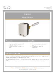
LN-RPTFTT Network RepeaterProvides an economical physical layer repeaterused to extend the maximum wire length of aLonWorks ® TP/FT-10 channel and/or the numberof nodes on that channel.FEATURES■■Extends free topology networks every 500m■■Enhances network signals■■24Vac supplySPECIFICATIONNetwork speed:78k Bit/secNetwork compatibility: TP/FT-10Power supply: 24Vac ±10%Ambient range:–10 to +60°C (14 to 140°F)Dimensions: 74 x 70 x 50mm (2.91 x 2.76 x 1.97”)Weight:300g (0.66 lb)Part code DescriptionLN-RPT-FTT LonWorks FTT Network RepeaterData sheet: LN-RPT-FTT.pdfLN-TERMLonWorks ® FTT TerminatorThe LonWorks ® terminator module is suitablefor terminating FTT-10 free topology and LPT-10link powered networks. The LN-TERM-FTT is alsosuitable for terminating Trend IQL networkswired in a free topology configuration.The terminator modules are designed toprovide electrical termination for twisted pairchannels. In a free topology TP/FT-10 segment,one LN-TERM-FTT terminator is required, andmay be placed anywhere on the segment.FEATURES■ ■ Polarity independent connection■ ■ CompactPart code DescriptionLN-TERM-FTT FTT-10 Free Topology TerminatorVolume Price Breaks are applicableUnit Price (10-19 and 20+)LN-TERM-FTTData sheet: LN-TERM-FTT.pdfPlease see price listLS-541Float SwitchThe LS-541 is intended to monitor the liquidlevel in a tank or vessel and provides a switchedoutput for local alarm, pump or valve control.The differential between switching is equivalentto approximately 15mm (0.59").The unit mounts into 1” BSPT female boss.Access is not required to the inside of the tank.SPECIFICATIONMounting:1” BSPT bossMedia: Non-aggressive fluids with specific gravity >0.75Operation:For high or low levelOperating temp: Ambient –40 to +85°C (–40 to 185°F),media 85°C max. (185°F)Operating pressure: 5 bar max. (72.5 psi max.)Materials: Float AcrylicRod BrassBellows Phosphor bronzeEnclosure ABS flame retardantSwitch rating:15(8)A SPDT @ 230Vac, VFCProtection:IP65Dimensions: Housing 113.5 x 65 x 62mm (4.47 x 2.56 x 2.44”)Float & rod 200 x 26mm dia. max. (7.87 x 1.02” dia.)Weight:300g (0.66 lb)Part code DescriptionLS-541 1” BSPT Float Switch (horizontal mount)Data sheet: LS-541.pdfVolume Price Breaks are applicableUnit Price (5+)LS-541Please see price listAir & Water Flow Air Quality & Gas Detection Controllers Input / Output Modules Water & Energy Metering Peripherals22www.sontay.com · Email sales@sontay.com
LS-CAPCapacitance Level SensorsThese sensors are designed for levelmeasurement in tanks or sumps providinga 4-20mA output relating to the level offluid in the tank. The LS-CAP1 is suitable forconducting liquids such as water whilst theLS-CAP2 is designed for use with clean, lowviscosity non-conducting liquids such as oil.FEATURES■■Suitable for a wide range of media■■Easy in-situ range adjustment■■4-20mA output■■No moving partsSPECIFICATIONOutput:Supply:Insertion length:Process connection:Process temperature:Ambient temperature:Max. pressure:Electrode insulation:Termination housing:Protection:Weight:4-20mA20 to 38Vdc0.5 to 3m variants (1.64 to 9.84 ft)1” BSP100°C max. (212°F)–20 to +60°C (–4 to +140°F)20 bar @ 20°C (290 psi @ 68°F)PolypropyleneABSIP658.24kg max. (18.17 lb max.)Part codeLS-CAP1-0.5LS-CAP1-1.0LS-CAP1-1.5LS-CAP1-2.0LS-CAP1-2.5LS-CAP1-3.0DescriptionSensors for Conducting Liquids0.5m (1.64 ft), Probe, Sensor1m (3.28 ft), Probe, Sensor1.5m (4.92ft) Probe, Sensor2m (6.56 ft), Probe, Sensor2.5m (8.20 ft), Probe, Sensor3m (9.84 ft), Probe, SensorPart code DescriptionSensors for Non-conducting LiquidsLS-CAP2-0.5 0.5m (1.64 ft), Probe, SensorLS-CAP2-1.0 1m (3.28 ft), Probe, SensorLS-CAP2-1.5 1.5m (4.92ft) Probe, SensorLS-CAP2-2.0 2m (6.56 ft), Probe, SensorLS-CAP2-2.5 2.5m (8.20 ft), Probe, SensorLS-CAP2-3.0 3m (9.84 ft), Probe, SensorData sheet: LS-CAP.pdfLS-FLLiquid Level Float SwitchesThe LS-FL series is a range of level switchessuitable for single or multi-level applicationswhere access is only available from the topsurface or where multiple level sensing isdesired from a single penetration.Units consist of a float, which is suspendedfrom a weighted cable. As the liquid levelchanges, the float follows the surface level,at the same time tilting due to its weightedrestraint. Inside the float are a number ofmicro switches which trigger as the float tips.SPECIFICATIONSwitch rating:6A @ 240VacStd. cable length:5m (16.40 ft)Min. switching level difference: 250mm (9.84”)Max. std. switching level diff: 1200mm (47.24”)Materials of construction: Polypropylene & PVCMin. fluid S.G.: 0.7Ambient temperature:0 to 55°C (32 to 131°F)Max. ext. pressure:200kPaProtection:IP68Dimensions: 170 x 155mm (6.69 x 6.10”)Weight:1.5kg (3.31 lb)Part codeLS-FL-1HLS-FL-1LLS-FL-2HDescriptionHigh Level, Alarm SwitchLow Level, Alarm SwitchEmptying Pump, Control SwitchPart code DescriptionLS-FL-2L Filling Pump, Control SwitchLS-FL-2LH High & Low Level Alarm SwitchData sheet: LS-FL.pdfLS-AFSAutomatic Float SwitchThe LS-AFS is designed for simple reliable waterlevel control. The float switch can be used tocontrol a pump for either tank filling or tankemptying (a high or low level cut-out). It iseasily achieved by positioning the float stops onthe cord. The electrical connections are easilymade inside the housing, via the terminal strip.Two M20 cable glands are provided for use withsuitable conduit.FEATURES■■Reliable■■Easy to install■■Easy to adjust■■Simple wiringSPECIFICATIONMax. switching voltage: 250VacCurrent rating: Resistive 20AInductive 8AFloat operating range: Maximum 700mm (27.56”)Minimum 50mm (1.97”)Material:Housing & float PolypropyleneWeights BrassCordNylonAmbient temp. range: 0 to 50°C (32 to 122°F)Media temperature: 4 to 50°C (39 to 122°F)Protection:IP22Weight:560g (1.23 lb)Part code DescriptionLS-AFS Automatic Float switchData sheet: LS-AFS.pdf& Interfaces Pressure Relative Humidity Wireless Devices Temperature Valves & ActuatorsUK Tel. +44 (0) 1732 861200 · Int. Tel. +44 (0) 1732 861225 · UK Fax +44 (0) 1732 861201 · Int. Fax +44 (0) 1732 86122623
LS-SPart codeLS-SN1LS-SN2LS-SS1LS-SS2LS-MCMG-GCompact Liquid Level SwitchA range of level switches designed for highand low liquid level detection in tanks andvessels. The LS-S types are for side mounting,type 1 switches fit from the inside of the tankand tighten on to a back nut whilst the type2 switches mount from the outside into atapered boss. The LS-TM is an easy to install TopMounting Level Switch, and has a reversiblefloat so that it can be used for either high orlow level alarms. The float is suspended from a5 metre (16.4 ft) PVC cable with a polyethyleneweight and is fully submersible and adjustable.FEATURES■■Low cost solution■■Easy to install■■Reliable switchingDescriptionPolypropylene Float SwitchesInternal fixing to M16 back nut½” NPT external fixingStainless Steel Float SwitchesInternal fixing to M16 back nut½” PF external fixingUltrasonic Level TransmitterThe LS-MC is an ultrasonic level transmitter formeasurement of liquids in tanks or sumps. The4-20mA output represents the distance betweenthe surface of the liquid being detected and thesensor. The LS-MC has an integral LCD display,three push buttons under the lid for security,and just eight parameters to set making it oneof the simplest ultrasonic level transmitters tocalibrate and use.FEATURES■■IP67 housing■■Fast speed of response,as much as 10m (32.8 ft) per minute■■Locking nut suppliedGas Meters (with pulsed output)SPECIFICATIONSwitch rating: LS-SN 230Vac/200Vdc @ 0.5A max.LS-SS 300Vac/350Vdc @1A max.LS-TM 240Vac/200Vdc @ 0.5A max.Contact (LS-TM):N/O, reversible to N/CMaterial: LS-SN PolypropyleneLS-SS Stainless steel 316LS-TM Cable PVC (5 metres / 16.4 ft)Float NylonWeight PolypropyleneTank fixing: LS-SN1 & SS1 M16 back nutLS-SN2 ½” NPTLS-SS2 ½” PFLS-TM1¼” BSPOperating range: LS-SN & LS-TM –20 to +80°C (–4 to +176°F)LS-SS–20 to +120°C (–4 to +248°F)Dimensions: 115 x 65mm (4.53 x 2.56”)Weight:280g max. (0.62 lb)Part code DescriptionTop Mounting Reversible Float SwitchLS-TMTop Mounting Level SwitchData sheets: LS-S.pdf ∙ LS-TM.pdfSPECIFICATIONMeasurement range: 0.3 to 8m (0.98 to 26.25 ft)Output:4-20mASupply:12 to 30Vdc loop poweredDisplay:Integral 4-digit LCDResolution: Better than 1mm (0.04”)Temperature range: –20 to +70°C (–4 to +158°F)Material: Transducer: PVDF | Housing: Glass filled nylonDimensions: 205.5 x 141mm overall (8.09 x 5.55”)Protection:IP67Weight:1.25kg (2.76 lb)Part codeLS-MCLS-NUTLS-FKData sheet: LS-MC.pdfDescriptionUltrasonic Level TransmitterAccessoriesAdditional fixing nutAdaptor flange for LS-UL3 fixingsOur range of diaphragm gas meters use proven,reliable technology to measure the volume ofgas used and then send a pulsed signal to a BMSsystem.FEATURES■■Diaphragm type■■All meters include pulsed output leadPart code DescriptionMax flow(m 3 /h)MG-G4 1” Screwed Gas Meter 6MG-G6 1” Screwed Gas Meter 10MG-G10 1½” Screwed Gas Meter 16MG-G16 1½” Screwed Gas Meter 25MG-G25 2” Screwed Gas Meter 40MG-G40 100mm (4”) Flanged Gas Meter 65MG-G65 100mm (4”) Flanged Gas Meter 100Data sheet: MG-G.pdfSPECIFICATIONMax. pressure:MG-G4 to G10 500mbar (7.3 psi)MG-G16 to G65 200mbar (2.9 psi)Material:Epoxy coated steelPulsed output specificationPulse value:MG-G4 to G10 0.01m³ per pulseMG-G16 to G65 0.1m³ per pulseMax. load current: 100mAMax. switching voltage: 24VdcMax. contact rating: 0.6WSwitch actuating time: 0.3sConnection type: 4-core flying leadLead length:2m (6.56 ft)Conformity:EEC 71/318, UNI-CIG 7987/7988 norms,OIML RegulationsAmbient temperature: 0 to 40°C (32 to 104°F)Weight:90kg max. (198 lb)Air & Water Flow Air Quality & Gas Detection Controllers Input / Output Modules Water & Energy Metering Peripherals24www.sontay.com · Email sales@sontay.com
How to size <strong>you</strong>r meter...<strong>Sontay</strong> offer a wide range of water & heat meteringUpper Limit (m³/h) 90 120 150 250 300 350 650Permanent (m³/h) 15 25 40 60 100 150 250Lower Limit (m³/h) 0.35 0.45 0.8 1.5 3 3.5 6.5Meter Code MW-xF-50 MW-xF-65 MW-xF-80 MW-xF-100 MW-xF-125 MW-F-150 MW-F-200Upper Limit (m³/h) 60 60 90 180 250 300 500Permanent (m³/h) 15 25 40 60 100 150 250Lower Limit (m³/h) 0.6 1 3.2 2 3 8 10Meter Code MW-F-50 MW-F-65 MW-F-80 MW-F-100 MW-F-125 MW-F-150 MW-F-200Upper Limit (m³/h) 3 5 7 12 12 20Permanent (m³/h) 1.5 2.5 3.5 6 6 10Lower Limit (l/h) 30 50 65 90 90 160Meter Code MW-MJx-20A MW-MJx-20B MW-MJx-25A MW-MJx-25B MW-MJx-32 MW-MJx-40Upper Limit (m³/h) 3 5 7 12 20 30Permanent (m³/h) 1.5 2.5 3.5 6 10 15Lower Limit (l/h) 15 25 35 60 100 450Meter Code MW-MxS-15 MW-xS-20 MW-xS-25 MW-xS-32 MW-xS-40 MW-CS-50Qi, Minimum (l/h) 12 30 50 To ensure <strong>you</strong> get the best performance and accuracy from <strong>you</strong>rQp, Nominal (m³/h) 0.6 1.5 2.5 meter it is essential that it is sized correctly. To do this <strong>you</strong> willQs, Maximum (l/h) 1.2 3 3.5 need to know <strong>you</strong>r permanent, upper limit and lower limit flowMeter Code MW-SJ-15A MW-SJ-15B MW-SJ-2 rates. Select the closest match from these tables.Flow parts for metering<strong>Sontay</strong> offer flow parts for two distinct applicationsFlow parts for waterdenoted in the <strong>Sontay</strong> catalogue as ‘water meters’Flow parts for heatingdenoted in the <strong>Sontay</strong> catalogue as ‘flow sensors’Are used specifically for sanitary water only, i.e. water withoutadditives or chemical treatment, and are designed for non-continuousflow, such as domestic cold and hot water supplies.■■The total daily flow should not exceed 3 hours, over a 6 year period■■Volumetric flows higher than this can lead to increased wear in thebearings of the impellor, causing inaccuracies in reading meters■■Water meters have a narrow fluid temperature range,typically between:0 to +90°C (32 to 194°F) for hot water meters0 to +30°C (32 to 86°F) for cold water metersCan be used with chemically treated water, and are designed forcontinuous or very high duty cycle flow conditions typically found inhot water heating systems.■■Flow sensors have a wider fluid temperature rangethan water meters, typically between 0 to +120°C (32 to 248°F)Note: Because of these distinct differences, only flow parts designedspecifically for heat metering should be used for heat meteringapplications. Although water meters can, in theory, be used for heatmeter applications, <strong>Sontay</strong> cannot warranty water meters if usedin this manner.Definitions of the heat meter flow rateAt which the heat meter shall function, without the maximum permissible errors being exceeded:Qs – upper limit Qp – permanent Qi – lower limit(the highest rate for short periods) (the highest rate continuously) (the lowest rate the meter shall function)The upper limit of the flow-rate, is the highestflow-rate at which the heat meter shallfunction for short periods (< 1 hour/day;< 200 hour/year), without the maximumpermissible errors being exceeded.The permanent flow-rate, is the highestflow-rate at which the heat meter shallfunction continuously without the maximumpermissible errors being exceeded.The lower limit of the flow-rate, is the lowestflow-rate above which the heat meter shallfunction without the maximum permissibleerrors being exceeded.& Interfaces Pressure Relative Humidity Wireless Devices Temperature Valves & ActuatorsUK Tel. +44 (0) 1732 861200 · Int. Tel. +44 (0) 1732 861225 · UK Fax +44 (0) 1732 861201 · Int. Fax +44 (0) 1732 86122625
MW-MDHeat Meter IntegratorsThe MW-MD range of heat meter integratorsuses the latest innovative technology tocalculate heat usage from heating and coolingsystems. They are for use with mechanical flowparts. With its dynamic measuring cycle eventhe smallest energy consumptions are reliablycollected. The large multifunction displaypermanently shows the heat consumption total,and by using the button it is possible to scrollthrough the display to show all data.FEATURES■■Simple operation■■Integral wall and DIN-rail mounting bracket■■Pulsed or M-Bus output options■■Measures heating or cooling andheat/coolingSPECIFICATIONTemp. range: 1 to 150°C (34 to 302°F)Temp. diff:3 to 120KBattery life: 6 years (optional 11 year)Display:Multifunction 8-digit + characters LCDOutput pulse: 30Vdc max. @ 20mAPulse duration: 400m/s
MW-CCold Water Meters (non-continuous flow)SCREWED COLD WATER METERS■■Inbuilt water strainer■■Complete with couplings■■Epoxy resin coated brass to DIN 50 930 part 6■■Dry dialPlease refer to data sheet or <strong>Sontay</strong>’s websitefor performance data, dimensions informationand pressure drop tables.SPECIFICATIONMax. fluid temperature: 30°C (86°F) (safety margin 50°C / 122°F)Max. working pressure: 16 bar (232 psi)Installation position: Horizontal, dial upwardsConformity: EN 14154MID:Annex B, Annex D, Annex I & MI-001Part codeSizeLitres /pulseQi(l/h)Qp(m 3 /h)Qs(m 3 /h)Cold Water Meters (Screw connections)MW-CS-15-A ½” 10 30 1.5 3MW-CS-15-B ½” 100 30 1.5 3MW-CS-20-A ¾” 10 50 2.5 5MW-CS-20-B ¾” 100 50 2.5 5MW-CS-25-A 1” 10 70 3.5 7MW-CS-25-B 1” 100 70 3.5 7MW-CS-32-A 1¼” 10 120 6 12MW-CS-32-B 1¼” 100 120 6 12MW-CS-40-B 1½” 100 200 10 20MW-CS-50-B 2” 100 450 15 30Data sheet: MW-S.pdfFLANGED COLD WATER METERS■■Cast Iron bodyPlease refer to data sheet or <strong>Sontay</strong>’s websitefor performance data, dimensions informationand pressure drop tables.SPECIFICATIONMax. fluid temperature: 30°C (86°F) (safety margin 50°C / 122°F)Max. working pressure: 16 bar (232 psi)Flanges:DIN 2501 PN16Installation position: Horizontal / vertical, dial upwardsConformity: EN 14154MID:Annex B, Annex D, Annex I & MI-001Part codeSizeLitres /pulseQi(m 3 /h)Qp(m 3 /h)Qs(m 3 /h)Cold Water Meters (Flanged connections)MW-CF-50-B 50mm (2”) 100 0.35 15 90MW-CF-65-B 65mm (2½”) 100 0.45 25 120MW-CF-80-B 80mm (3”) 100 0.8 40 150MW-CF-80-C 80mm (3”) 1000 0.8 40 150MW-CF-100-B 100mm (4”) 100 1.5 60 250MW-CF-100-C 100mm (4”) 1000 1.5 60 250MW-CF-125-C 125mm (5”) 1000 3 100 300MW-CF-150-C 150mm (6”) 1000 3.5 150 350MW-CF-200-C 200mm (8”) 1000 6.5 250 650Data sheet: MW-F.pdfMW-HHot Water Meters (non-continuous flow)SCREWED HOT WATER METERS■■Inbuilt water strainer■■Complete with couplings■■Epoxy resin coated brass to DIN 50 930 part 6■■Dry dialPlease refer to data sheet or <strong>Sontay</strong>’s websitefor performance data, dimensions informationand pressure drop tables.SPECIFICATIONMax. fluid temperature: 90°C (194°F) (safety margin 120°C / 248°F)Max. working pressure: 16 bar (232 psi)Installation position: Horizontal, dial upwardsConformity: EN 14154MID:Annex B, Annex D, Annex I & MI-001Part codeSizeLitres /pulseQi(l/h)Qp(m 3 /h)Qs(m 3 /h)Cold Water Meters (Screw connections)MW-HS-15-A ½” 10 30 1.5 3MW-HS-15-B ½” 100 30 1.5 3MW-HS-20-A ¾” 10 50 2.5 5MW-HS-20-B ¾” 100 50 2.5 5MW-HS-25-A 1” 10 70 3.5 7MW-HS-25-B 1” 100 70 3.5 7MW-HS-32-A 1¼” 10 120 6 12MW-HS-32-B 1¼” 100 120 6 12MW-HS-40-B 1½” 100 200 10 20Data sheet: MW-S.pdfFLANGED HOT WATER METERS■■Cast Iron bodyPlease refer to data sheet or <strong>Sontay</strong>’s websitefor performance data, dimensions informationand pressure drop tables.SPECIFICATIONMax. fluid temperature: 90°C (194°F) (safety margin 120°C / 248°F)Max. working pressure: 16 bar (232 psi)Flanges:DIN 2501 PN16Installation position: Horizontal / vertical, dial upwardsConformity: EN 14154MID:Annex B, Annex D, Annex I & MI-001Part codeSizeLitres /pulseQi(m 3 /h)Qp(m 3 /h)Qs(m 3 /h)Hot Water Meters (Flanged connections)MW-HF-50-B 50mm (2”) 100 0.35 15 90MW-HF-65-B 65mm (2½”) 100 0.45 25 120MW-HF-80-B 80mm (3”) 100 0.8 40 150MW-HF-80-C 80mm (3”) 1000 0.8 40 150MW-HF-100-B 100mm (4”) 100 1.5 60 250MW-HF-100-C 100mm (4”) 1000 1.5 60 250MW-HF-125-C 125mm (5”) 1000 3 100 300MW-HF-150-C 150mm (6”) 1000 3.5 150 350MW-HF-200-C 200mm (8”) 1000 6.5 250 650Data sheet: MW-F.pdf& Interfaces Pressure Relative Humidity Wireless Devices Temperature Valves & ActuatorsUK Tel. +44 (0) 1732 861200 · Int. Tel. +44 (0) 1732 861225 · UK Fax +44 (0) 1732 861201 · Int. Fax +44 (0) 1732 86122629
MW-UUltrasonic Flow SensorsUltrasonic heat sensors have no moving partswhich makes them almost wear free andnoiseless. They measure the flow by using thetransit time principle, one ultrasonic signal islaunched in the flow direction and one againstthe flow direction. The calculator uses thelatest innovative technology to calculate heatusage from heating systems. With its dynamicmeasuring cycle even the smallest energyconsumptions are reliably collected. The largemultifunction display permanently shows theheat consumption total; it is possible to scrollthrough the display to show all data.SPECIFICATIONNominal flow rate: Qp 0.6 to Qp 60m 3 /hMax. static pressure: Screwed 16 bar (232 psi)Flanged 25 bar (362 psi)Body materials: BrassTemperature range: Heating 10 to 130°C (50 to 266˚F)Cooling 10 to 50°C (50 to 122˚F)Maximum temp: 50°C (122˚F) for 2000 hTemperature diff: 3 to 120KSupply:3.6V Lithium batteryBattery life: 6 years (optional 11 year available upon request)Display:Multifunction 8-digit + characters LCDOutput pulse: 30Vdc max. @ 20mAPulse duration: 400m/s
An introduction to Air Pressure<strong>Sontay</strong> offer a wide range of pressure sensing and switching productsFilterCooling CoilMixing DamperOutside AirAV-EP Air Velocity ProbeReturnAirPA-500, PA-267 &PA-699 Air DP SensorsSupply AirPA-930 Air DP SwitchPA-930Air DP SwitchesThese are highly sensitive air differentialpressure switches, suitable for providingan indication of fan status and ‘dirty filter’conditions. The switching setpoint is adjustedby means of a knob mounted under the maincover. Units are supplied complete with a ductfixing kit.FEATURES■■Duct fixing kit included■■IP54 or IP65 housing optionSPECIFICATIONOperating ranges: Type: Adjustment range:PA-930-80 20 to 200Pa (0.08 to 0.80”w/c)PA-930-83 50 to 500Pa (0.20 to 2”w/c)PA-930-85 200 to 1000Pa (0.8 to 4”w/c)Max. operating pressure: 5000Pa (20”w/c)Pressure connections: 6mm i/d push-on tubingElectrical rating:1.5A (0.4)/250Vac AgCdO contactsConnections:Spade terminals and screw terminal adaptorsfor cable up to 1.5mm 2 max.Housing material:Plastic mouldingDimensions: IP54 85mm (3.35”) dia. x 59mm (2.32”)IP65 130 x 130 x 99mm (5.12 x 5.12 x 3.90”)Protection:IP54 or IP65Ambient range: Temperature –20 to +85 o C (–4 to +185°F)RH0 to 95% RH, non-condensingWeight:250g (0.55 lb)Part code DescriptionIP54 Switch HousingPA-930-80 20 to 200Pa (0.08 to 0.80”w/c) SwitchPA-930-83 50 to 500Pa (0.20 to 2”w/c) “PA-930-85 200 to 1000Pa (0.8 to 4”w/c) “Volume Price Breaks are applicableUnit Price (10-19 and 20+)PA-930-80PA-930-83PA-930-85The IP65 option DP switch isconnected (in the factory)to custom made nipplesmounted in the housing.This eliminates awkwardpiping on-site and makesthe product much easierto fit, and reducesinstallation time.Please see price listPart code DescriptionIP65 Switch Housing (including switch)PA-930-80-IP65 20 to 200Pa (0.08 to 0.80”w/c) SwitchPA-930-83-IP65 50 to 500Pa (0.20 to 2”w/c) “PA-930-85-IP65 200 to 1000Pa (0.8 to 4”w/c) “AccessoriesPA-930-B Right angle mounting bracketDFKDuct fixing kitTEE Tee piece air pressure (pack of 10)PA-TUBE-8MM PVC tube 8mm o/d x 1.5mm wall, 30m reelData sheet: PA-930.pdfNote: A duct fixing kit (DFK) is supplied with the switch, consisting of 2m(6.56 ft) 5mm (0.20") i/d plastic tubing, 2 x pitot tubes and 4 x fixing screws.& Interfaces Pressure Relative Humidity Wireless Devices Temperature Valves & ActuatorsUK Tel. +44 (0) 1732 861200 · Int. Tel. +44 (0) 1732 861225 · UK Fax +44 (0) 1732 861201 · Int. Fax +44 (0) 1732 86122631
PA-500Multi-range Air DP SensorThe PA-500 differential pressure transmitteris ideal for measuring filter conditions, as wellas many other applications in ventilation/airconditioning systems in buildings, laboratory’sand clean rooms (air and non-corrosive gases).The sensors feature field-selectable outputtypes and 4 pressure ranges, which are easilydefined by user selection switches inside therugged IP65 housing.FEATURES■■User selectable measurement range andoutput type■■Duct fixing kit included■■Pre-wired for quick & easy installation■■IP65 housingSPECIFICATIONPower supply: Current output 24Vdc ±10% (3-wire)Voltage output 24Vac/dc ±10%Power consumption: 1VAMeasurement ranges: SelectableDP Resolution: 0 to 500Pa (2”w/c) 0.2% fsOthers0.1% fsPressure non-linearity: 0 to 500Pa (2”w/c) 0-20% fs = ±2%,20-100% = ±5%Others5bar (72.5psi)Pressure connections: Push fit for 6.2mm i/d tubeElectrical connections: 1m (3.2ft) flying leadHousing: Material Flame retardant ABSDimensions 55mm (2.17”) x 90mm(3.54”) dia.Protection:IP65Ambient range: Temperature 0 to 40°C (32 to 104°F)RH0 to 85% RH, non-condensingWeight:220g (0.49lb)Part code DescriptionPA-500 0 to 50, 100, 300 & 500PaMulti Range Selectable(0 to 0.2, 0 to 0.4, 0 to 1.2 & 0 to 2”w/c)0-10Vdc or 4-20mA (3-wire) Selectable OutputAccessoriesDFKDuct fixing kitTEE Tee piece air pressure (pack of 10)PA-TUBE-8MM PVC tube 8mm o/d x 1.5mm wall, 30m reelData sheet: PA-500.pdfNote: A duct fixing kit (DFK) is supplied with the sensor, consisting of 2m(6.56 ft) 5mm (0.20") i/d plastic tubing, 2 x pitot tubes and 4 x fixing screws.PA-267Air DP SensorsThese sensors are designed for differentialpressure measurements of air and otherneutral gases. The unit is especially suitedfor measurement and control in HVACapplications.The measurement cell uses an advanced designcapacitive element to ensure excellent linearityand stability.FEATURES■■Two accuracy levels to suit differentapplications■■Available in ranges as low as 0-25Pa (0 to0.10”w/c)■■Integral LCD option■■IP65 housing with 20mm cable entrygland■■Duct fixing kit includedPart code DescriptionPA-267-25 0 to 25Pa (0 to 0.10”w/c), 4-20mA TransmitterPA-267-50 0 to 50Pa (0 to 0.20”w/c), "PA-267-100 0 to 100Pa (0 to 0.40”w/c), "PA-267-300 0 to 300Pa (0 to 1.20”w/c), "PA-267-500 0 to 500Pa (0 to 2.01”w/c), "PA-267-1000 0 to 1000Pa (0 to 4.01”w/c), "PA-267-1600 0 to 1600Pa (0 to 6.42”w/c), "PA-267-2500 0 to 2500Pa (0 to 10.04”w/c), "PA-267-3000 0 to 3000Pa (0 to 12.04”w/c), "Suffixes (add to above part code)-V 0-10V voltage output-B Bi-directional-AHHigh accuracy-LCD * Integral LCD displaySPECIFICATIONAccuracies: Standard HighOverall ±1.00% fsd ±0.40% fsdLinearity ±0.98% fsd ±0.33% fsdHysteresis ±0.20% fsd ±0.20% fsdRepeatability ±0.10% fsd ±0.10% fsdTotal ±1.28% fsd ±0.63% fsdThermal effect: ±0.06% per °COver pressure:10 psi (68 kPa)Pressure connections: Push fit for 6mm (0.24”) i/d tubeOutput: Current 4-20mA, load: 100 to 800ΩVoltage 0-10Vdc (o/p impedance
PA-699Multi-range Air DP Sensors<strong>Sontay</strong>’s range of field selectable multi-rangedifferential pressure transmitters, incorporatea proven ceramic fulcrum lever technology forpressure measurement.The PA-699 has three field selectable ranges inone unit, providing versatility for a multitudeof applications.FEATURES■■Adjustable measurement range■■IP65 housing■■Duct fixing kit included■■Compact constructionSPECIFICATIONAccuracy, total of linearity, PA-699-01 to 04 ±1.0 max.hysteresis & repeatability (% fs): Others ±0.6Thermal effect (typical % fs/°C): TC zero point TC sensitivityPA-699-01 ±0.02 ±0.03PA-699-02 ±0.02 ±0.03PA-699-03 ±0.02 ±0.02PA-699-04 ±0.01 ±0.01Others ±0.01 ±0.01Rupture pressure: 2 x overload at ambient temp.Power supply:Current output 8 to 33VdcVoltage 13.5 to 33Vdc or 24Vac ±15%Diaphragm:SiliconeHousing:Polycarbonate PCTemperature: Medium & ambient 0 to 70°C (32 to 158°F)Protection:IP65Dimensions: 92 x 75 x 47.9mm (3.62 x 2.95 x 1.89”)Weight:92g (0.20 lb)Part codePA-699-01PA-699-02PA-699-03PA-699-04PA-699-05PA-699-06PA-699-07PA-699-08DescriptionBi-directional, 30, 50 & 100Pa,(0.12, 0.20 & 0.40”w/c) 4-20mA Multi Range0 to 30, 50 & 100Pa,(0.12, 0.20 & 0.40”w/c) 4-20mA Multi Range0 to 50, 100 & 300Pa,(0.20, 0.40 & 1.20”w/c) 4-20mA Multi Range0 to 100, 300 & 500Pa,(0.40, 1.20 & 2.01”w/c) 4-20mA Multi Range0 to 300, 500 & 1000Pa,(1.20, 2.01 & 4.01”w/c) 4-20mA Multi Range0 to 500, 1000 & 1600Pa,(2.01, 4.01 & 6.42”w/c) 4-20mA Multi Range0 to 1000, 1600, 2500Pa,(4.01, 6.42 & 10.04”w/c) 4-20mA Multi Range0 to 1600, 2500 & 5000Pa,(6.42, 10.04 & 20.07”w/c) 4-20mA Multi RangePart code DescriptionSuffixes (add to above part code)-V 0-10V voltage output-LCDIntegral LCD optionAccessoriesDFKDuct fixing kitTEE Tee piece air pressure (pack of 10)PA-TUBE-8MM PVC tube 8mm (0.31”) o/d x 1.5mm (0.06”)wall,30m (98.5 ft) reelPA-BRK DIN-rail bracketPA-699-CAL * Calibration certificateData sheet: PA-699.pdfNotes: * This option must be specified at time of sensor order.They are built to order and not available ex-stock.••A duct fixing kit (DFK) is supplied with the sensor, consisting of 2m (6.56 ft)5mm (0.20") i/d plastic tubing, 2 x pitot tubes and 4 x fixing screws.& Interfaces Pressure Relative Humidity Wireless Devices Temperature Valves & ActuatorsUK Tel. +44 (0) 1732 861200 · Int. Tel. +44 (0) 1732 861225 · UK Fax +44 (0) 1732 861201 · Int. Fax +44 (0) 1732 86122633
Liquid Pressure<strong>Sontay</strong> offer a wide range of pressure sensing and switching productsMonitor flow andprove pumps,chillers and valves.PL-PSAPL-692This sensor can be used tomeasure static pressure ina large range of liquids andgases that are compatiblewith a Viton seal.This sensor can beused to measure staticpressure in a large rangeof liquids and gasesthat are compatiblewith a Viton seal.PL-528PL-FD113 or PL-630Use these sensors to monitorflow status. The PL-FD113 issuited to pumps, chillers andvalves, whereas the PL-630 isideal for heating, ventilationand air conditioning.PL-528Static Pressure TransmitterThe PL-528 range of static pressure transmittersare suitable for use with a large range ofliquids and gases compatible with the FPM(Viton) seal. The pressure transmitter is basedon proven ceramic technology for exceptionalperformance speed and reliability.FEATURES■■Compact rugged construction■■Negligible temperature influence onaccuracy■■IP65 protection■■Electrical terminals and gland toDIN EN175 301-803-A■■Supply short circuit & polarityreversal protectionPart code Description4-20mA Output (2-wire loop powered)PL-528-1 0 to 1 bar (0 to 14.5 psi) Static Pressure SensorPL-528-1.6 0 to 1.6 bar (0 to 23.2 psi) ”PL-528-2.5 0 to 2.5 bar (0 to 36.3 psi) ”PL-528-4 0 to 4 bar (0 to 58 psi) ”PL-528-6 0 to 6 bar (0 to 87 psi) ”PL-528-10 0 to 10 bar (0 to 145 psi) ”PL-528-16 0 to 16 bar (0 to 232 psi) ”PL-528-25 0 to 25 bar (0 to 362.6 psi) ”PL-528-40 0 to 40 bar (0 to 580 psi) ”0-10Vdc OutputPL-528-1-V 0 to 1 bar (0 to 14.5 psi Static Pressure SensorPL-528-1.6-V 0 to 1.6 bar (0 to 23.2 psi) ”PL-528-2.5-V 0 to 2.5 bar (0 to 36.3 psi) ”PL-528-4-V 0 to 4 bar (0 to 58 psi) ”SPECIFICATIONSupply voltage: PL-528-x 7Vdc to 33VdcPL-528-x-V 12Vdc to 33Vdc or 24Vac ±15%Output: PL-528-x 4-20mAPL-528-x-V 0-10VdcResponse time:
PL-630Differential Pressure SwitchesIdeal for flow monitoring and provingapplications in heating, ventilating and airconditioningsystems.FEATURES■■Over-pressure safety capabilityto 10 bar (145 psi) / 20 bar (290 psi)■■Mechanically isolated switching chamberfor safety and reliability■■Medium temperatures to 80°C (176°F)■■Rugged construction■■Adjustable setting and differentialSPECIFICATIONMax. operatingpressure and overloadon one side (P1>P2):With range ≤ 200 mbar (2.9 psi) = 10 bar (145 psi)With range 150 to 5000 mbar (2.2 to 72.5 psi)= 20 bar (290 psi)Lowest turn-on pressure: 15 mbar (0.2 psi)1/8” BSP femaleWater, air and steam (with pigtail siphon)1A(0.5A) @ 250VacChangeover contact–10 to +80°C (14 to 176°F)IP65Pressure connection:Media:Electrical rating:Contact system:Operating range:Protection:Dimensions: 110 x 65mm (4.33 x 2.56”)Weight:1.08 kg (2.38 lb)Part code DescriptionPL-630-0.02 6 to 20 mbar (0.1 to 0.3 psi) Diff. Pressure SwitchPL-630-0.06 15 to 60 mbar (0.2 to 0.9 psi) ”PL-630-0.2 40 to 200 mbar (0.6 to 2.9 psi) ”PL-630-1 0.15 to 1 bar (2.2 to 14.5 psi) Diff. Pressure SwitchPL-630-3 1 to 3 bar (14.5 to 43.5 psi) ”PL-630-5.5 2 to 5.5 bar (29 to 79.8 psi) ”Data sheet: PL-630.pdfNote: A mounting bracket is supplied with the switch.PL-FD113Liquid DP SwitchLiquid differential pressure switch suitable formonitoring flow status across pumps, chillers,valves etc. The switch has an adjustable setpoint from 0.3 bar to 4.5 bar (4.4 to 65.3 psi)with a fixed differential of 0.2 bar (2.9 psi).FEATURES■■SPDT switch■■Single unit covers a wide pressure range■■Simple to configureSPECIFICATIONRange:0.3 to 4.5 bar (4.4 to 65.3 psi)Switching differential: 0.2 bar (2.9 psi)Pipe connections: ¼” BSP femaleAmbient temperature: –10 to +70°C (14 to 158˚F)Liquid temperature: 70°C max. (158˚F)Switch rating:3A @ 230VacProtection:IP30Dimensions: 128 x 175 x 48mm (5.04 x 6.89 x 1.89”)Weight:800g (1.76 lb)Part codePL-FD113Description0.3 to 4.5 bar (4.4 to 65.3 psi) Liquid DP SwitchVolume Price Breaks are applicableUnit Price (20+)PL-FD113Data sheet: PL-FD113.pdfPlease see price listNote: A mounting bracket is supplied with the switch.Air & Water Flow Air Quality & Gas Detection Controllers Input / Output Modules Water & Energy Metering Peripherals36www.sontay.com · Email sales@sontay.com
PL-692Differential Pressure SensorsFor high accuracy and close controlapplications, the PL-692 features ceramicsensing technology for exceptional accuracyand reliability. The amplified sensingtechnologies allow high temperature stabilityand no creepage associated with mechanicalsystems.FEATURES■■Current and voltage output models■■Supplied with 6mm o/d fittings■■Easy installation and wiring■■Complete with 1.5m (4.92 ft) cable, readyconnected■■High temperature stabilitySPECIFICATIONSupply voltage: 4-20mA 11 to 33Vdc0-10Vdc 18 to 33Vdc or 24Vac ±15%Response time:P2): 10 bar (145 psi)Pressure connection: 1/8 ” BSP femaleMedia:Water, air and steam (with pigtail siphon)Operating range: –10 to +80°C (14 to 176˚F)Protection:IP65Dimensions: 110 x 65mm (4.33 x 2.56”)Weight:940g (2.07 lb)Part codePL-652-0.05PL-652-0.05-VPL-652-CAL *Data sheet: PL-652.pdfDescription4-20mA Output (3-wire)0 to 50 mbar (0 to 0.7 psi) Diff. Pressure Sensor0-10Vdc Output0 to 50 mbar (0 to 0.7 psi) Diff. Pressure SensorAccessoryCalibration certificateNotes:1. A mounting bracket is supplied with the sensor.2. * This option must be specified at the time of sensor order.It is built to order and not available ex-stock.& Interfaces Pressure Relative Humidity Wireless Devices Temperature Valves & ActuatorsUK Tel. +44 (0) 1732 861200 · Int. Tel. +44 (0) 1732 861225 · UK Fax +44 (0) 1732 861201 · Int. Fax +44 (0) 1732 86122637
PM-CT-XCurrent TransformersThe <strong>Sontay</strong> range of current transformers areavailable in moulded, split core and ring types.They all suitable for use with the PM-EM rangeof kWh meters.The split core Current transformers arepartially useful for retrofits, upgrades andtemporary installations, as they can befitted without any disruption to the existinginstallation.FEATURES■■Ratings from 50 to 800A■■5A secondary currentPart code DescriptionMoulded TypesPM-CT-M100 100A, 2.5VA Current TransformerPM-CT-M150 150A, 2.5VA “PM-CT-M200 200A, 5VA “PM-CT-M250 250A, 5VA “PM-CT-M300 300A, 5VA “PM-CT-M400 400A, 5VA “PM-CT-M500 500A, 10VA “PM-CT-M600 600A, 10VA “PM-CT-M800 800A, 10VA “Split Core TypesPM-CT-100SC 100A, 1VA Current TransformerPM-CT-150SC 150A, 1.5VA “PM-CT-200SC 200A, 2.5VA “SPECIFICATIONOverload:1.2 x rated current (continuous)Frequency: 50/60HzInsulation level: 3kV (50Hz) for 1 minute (not PM-CT-M)Connections: PM-CT-M Screw terminalsPM-CT-xSC 1m tails (3.28 ft)PM-CT-R M6 lug terminalsConformity: PM-CT-xSC IEC185, BS7626, BSEB 60044-1PM-CT-R IEC44-1, IEC185, BS7626Ambient range: Humidity up to 95% RH (non-condensing)Temperature –20 to +85°C (PM-CT-M) (–4 to +185°F)–30 to +85°C (others) (–22 to +185°F)Weight:750g max. (1.65 lb)Part code DescriptionSplit Core TypesPM-CT-250SC 250A, 2.5VA Current TransformerPM-CT-300SC 300A, 2.5VA “PM-CT-400SC 400A, 5VA “PM-CT-500SC 500A, 5VA “PM-CT-600SC 600A, 5VA “PM-CT-800SC 800A, 5VA “Ring TypesPM-CT-R50 50A, 2.5VA Current TransformerPM-CT-R100 100A, 10VA “PM-CT-R150 150A, 15VA “PM-CT-R250 250A, 15VA “PM-CT-R300 300A, 15VA “PM-CT-R400 400A, 15VA “PM-CT-R500 500A, 15VA “PM-CT-R800 800A, 15VA “Data sheets: PM-CT-M.pdf ∙ PM-xSC.pdf ∙ PM-CT-R.pdfPM-EM21Energy Analyser (DIN-rail or panel mounted)The PM-EM21 is a compact energy meter thathas a removable front LCD display that allowsit to be either DIN-rail or panel mounted.The energy meter is designed for active andreactive energy metering. All operations,including programming and viewing up toseven display pages are performed using thetwo push buttons on the detachable display. Itis possible to block the access to programmingby means of a trimmer position on the rearof the display. Standard meters are non-MID.For billing use, add annex -B+D option. Extrasystem information is required please contact<strong>Sontay</strong> Support.FEATURES■■Pulsed or ModBus output options■■Self powered■■5A CT secondary current■■Compact size■■Detachable display■■Multi-use housing for both DIN-rail andpanel mounting applicationsAPPLICATIONS■■3-Phase, 4-wire balanced & unbalanced load■■3-Phase, 3-wire balanced & unbalanced load■■2-Phase, 3-wire■■1-Phase, 2-wireCHARACTERISTICSMeasurements: System W, var, PF, Hz, Phase-sequenceSingle-phase VLL, VLN, A, PF, kWh, kvarhSPECIFICATIONFrequency:45 to 65HzDisplay:2 linesHousing: Nylon PA66, self-extinguishing UL 94 V-0Mounting:DIN-rail or panelOutput types: Pulse Open collectorModBus RS485RS 485: Address Programmable, 1 to 247Baud-rate 9600 bit/sRefresh time: 1/sAmbient: Humidity 0 to 90% (non-condensing)Temperature –25 to +55°C (–13 to +131°F)Protection:IP50 (front)Dimensions: 72 x 72 x 65mm (2.83 x 2.83 x 2.56”)Weight:260g (0.57 lb)Part code DescriptionPM-EM21-P Energy Analyser – Pulsed OutputPM-EM21-M Energy Analyser – ModBus OutputOption (add to part code above)-B+DAnnex B+D CertificationData sheet: PM-EM21.pdfAir & Water Flow Air Quality & Gas Detection Controllers Input / Output Modules Water & Energy Metering Peripherals38www.sontay.com · Email sales@sontay.com
PM-CSXCurrent Switches<strong>Sontay</strong>’s new range of current switches offeradjustable or fixed setpoint’s and providesaccurate, reliable and maintenance-freeoperation. Output switching options include30Vac/dc @ 1A or 240Vac @ 1A, with currentratings of up to 150A.Both <strong>version</strong>s have a unique self-gripping featurewhich allows the switch to literally clip on to acable without the need for a base mounting plate.APPLICATIONS■ Detection of fan belt breakage■ Detection of motor failure■ Verifying lighting circuits■ Monitoring critical motors (compressors etc.)■ Process equipment statusADJUSTABLE SETPOINT TYPESAllow for easy detection of broken drive belts, drive belt slip or pump couplingshear. A typical HVAC motor that loses its load has a reduction of current draw ofup to 50%.FEATURES■ Adjustable set-point■ More reliable and cost-effective than differential pressure switches■ 100% solid-state output, no moving parts to fail■ Output status LEDs for fast setup■ Self-poweredFIXED SETPOINT TYPESProvide a cost-effective solution for monitoring the status of unit vents, exhaustfans, recirculation pumps and other fixed loads where belt loss is not a concernFEATURES■ More reliable for status than relays across auxiliary contacts■ Ideal for lighting status■ Monitor status of fans, pumps, motors and other electrical loadsSPECIFICATIONSupply:Self-powered from monitored lineInsulation class: 600VacTrip setpoint: PM-CSA01 - 0.75 to 150A PM-CSF01 - 0.35A or lessPM-CSA02 - 0.5 to 150A PM-CSF02 - 0.25A or lessPM-CSF03 - 0.5A or lessSensor power: Induced from monitored conductorTemperature range: –35 to +60°C (–31 to +140°F)Humidity range: 0 to 95%, non-condensingDimensions: Split core types 65 x 50 x 30mm (2.56 x 1.97 x 1.18”hole 13 x 13mm (0.51 x 0.51”),self-gripping clampSolid core types 53 x 37 x 24mm (2.09 x 1.46 x 0.94”)hole 13mm (0.51”) diaConformity: CE markedWeight:100g (0.22lb) max.Part code DescriptionAdjustable Setpoint TypesPM-CSA01 0.75 to 150A 30Vac/dc, split corePM-CSA02 0.5 to 150A 30Vac/dc, solid coreFixed Setpoint TypesPM-CSF01 0.35 to 150A 30Vac/dc, split corePM-CSF02 0.25 to 150A 30Vac/dc, split corePM-CSF03 0.50 to 150A 240Vac, split coreVolume Price Breaks are applicableUnit Price (5+)PM-CSA01PM-CSA02PM-CSF01PM-CSF02PM-CSF03Please see price listData sheet: PM-CS.pdfPS24Vdc Output Supplies<strong>Sontay</strong>’s range of 24Vdc power supplies offeradvanced protection, self-diagnostics andself-test facilities, to make installation andcommissioning quicker and easier than everbefore. 240Vac and 24Vac input <strong>version</strong>sare available, all featuring over-current andover-voltage protection, LED indication of awide range of conditions, an optional alarmrelay output for loss of input and on-PCB resetbutton.The 24Vac input typeis available in two <strong>version</strong>s:1. PS-24-24DC-1A – the input 0V andthe output 0V are NOT common.2. PS-24-24DC-E – the input 0V and theoutput 0V are common on the PCB.This allows the user a choice, depending onwhat type of field wiring is installed.FEATURES■■Advanced LED indication of faults■■ON-PCB self-test function■■Polarity independent outputSPECIFICATIONSupply:240Vac and 24VacOutput:24Vdc @ 1ALED indication: Power ON, low output voltage, high outputvoltage, output voltage within limits, reset buttonpressed, self-test in progressTemperature range: –10 to +50°C (14 to 122°F)Humidity range: 0 to 95%, non-condensingDimensions: PS-240-24DC-1A 104 x 118 x 88mm (4.09 x 4.65 x 3.46”)PS-24-24DC-1A 104 x 74 x 65mm (4.09 x 2.91 x 2.56”)PS-24-24DC-E 104 x 74 x 70mm (4.09 x 2.91 x 2.76”)Weights:PS-240-24DC-1A 620g (1.37 lb)PS-24-24DC-1A 120g (0.26 lb)PS-24-24DC-E 120g (0.26 lb)Part code DescriptionPS-24-24DC-1A 24Vac-24Vdc, 1A floating Supply ModulePS-24-24DC-E 24Vac-24Vdc, grounded Supply ModulePS-230-24DC-1A 240Vac-24Vdc, 1A Supply ModuleData sheets: PS-24-1A.pdf ∙ PS-24-E.pdf ∙ PS-230.pdfAir & Water Flow Air Quality & Gas Detection Controllers Input / Output Modules Water & Energy Metering Peripherals40www.sontay.com · Email sales@sontay.com
RE-PR11.5, 3 and 6kW, Single-phase ControllersThis range of triac control assemblies providefull seamless control of single phase electricheating loads.The controllers incorporate a temperature trip,automatic reset, integral semi-conductor fusesand heatsink.FEATURES■■0-10Vdc or 0-5Vdc control input■■Over temperature protection with auto reset■■No additional heatsinks required■■No external 24V supply required■■No external RFI filters requiredPart code Description Current ratingRE-PR1-F-1.5 1.5kW Controller 6.3ARE-PR1-F-3 3kW Controller 12.5ARE-PR1-F-6 6kW Controller 25ASPECIFICATIONInput signal: 0-5Vdc or 0-10VdcSupply:230Vac RMS ±10%, 50/60HzOver temp: Trip-in temp. @ 90°C (194°F) ±1°C (±1.8°F)Trip-out temp. @ 85°C (185°F) ±1°C (±1.8°F)Fault condition: Over temp. LED flashes in 0.5 sec pulse burstsLoss of signal LED flashes in 1 sec pulse burstsAmbient temp: 65°C (149°F) – maximum operationalDimensions: RE-PR1-F-1.5 112 x 95 x 75mm (4.41 x 3.74 x 2.95”)RE-PR1-F-3 112 x 95 x 75mm (4.41 x 3.74 x 2.95”)RE-PR1-F-6 112 x 95 x 85mm (4.41 x 3.74 x 3.35”)Weights:RE-PR1-F-1.5 - 280g (0.62 lb), RE-PR1-F-3 - 280g (0.62 lb)RE-PR1-F-6 - 700g (1.54 lb)Part codeRE-PR1-F15102RE-PR1-F15103RE-PR1-F11307RE-PR1-F-6-GDData sheet: RE-PR1-F.pdfDescriptionAccessories1.5kW Replacement fuse3kW Replacement fuse6kW Replacement fuseReplacement 6kW guardRE-PR312 and 18kW, 3-phase ControllersThe RE-PR3-DIN-xx range of thyristor stacksprovides full seamless control of 415V supplyloads. They incorporate a temperature trip,automatic reset, alarm output, LED indication(output on) and heatsink.FEATURES■■0-10Vdc control input■■Over temperature protection with auto reset■■No additional heatsinks requiredPart code Description Current ratingRE-PR3-DIN-12 12kW Controller 16.7A per phaseRE-PR3-DIN-18 18kW Controller 25A per phaseData sheet: RE-PR3-DIN.pdfSPECIFICATIONInput signal: 0-10VdcExternal supply: (control) 24Vac/dc ±10%, 50HzSupply:(load) 3-Phase, 400Vac RMS ±10%, 50HzFault condition: 24Vac/dc (as power supply)24V alarm terminal normally present, drops to 0V in theevent of over-temp. or loss of external power supplyLED indication: T1 & T3 LED pulse when output is ‘ON’Mounting:DIN-railAmbient temp: 40°C (104°F) – max. operationalDimensions: RE-PR3-DIN-12 217 x 92 x 85mm (8.54 x 3.62 x 3.35”)RE-PR3-DIN-18 217 x 92 x 107mm (8.54 x 3.62 x 4.21”)Weights: RE-PR3-DIN-12 600g (1.32 lb)RE-PR3-DIN-18 960g (2.12 lb)RE-PR3-E27, 36, 54, 86 and 105 kW, 3-phase ControllersSPECIFICATIONInput signal:Supply:These thyristor control assemblies provide fullseamless control of 3-phase resistive loads ofup to 27, 36, 54, and 105 kW. The controllersincorporate a temperature trip, automaticreset, alarm output, LED indication (outputon) and heatsink.FEATURES■■0-5Vdc, 0-10Vdc or 4-20mA control input■■Over temperature protection with auto reset■■No additional heatsinks required■■No external 24V supply required0-5Vdc, 0-10Vdc or 4-20mA(control) 24Vac/dc ±10% (by dipswitch)(load) 3-Phase, 400Vac RMS ±10%, 50/60HzOver temp:Trip-in temp. @ 90°C (194°F) ±1°C (±1.8°F)Trip-out temp. @ 85°C (185°F) ±1°C (±1.8°F)Fault condition: Relay rated at 230Vac @ 8AFault status:Phase loss – LED flashes in 1.5 sec pulse burstsSensor loss – LED flashes in 0.5 sec pulse burstsAmbient temp: 65°C (149°F) - maximum operationalMounting:PanelDimensions: RE-PR3-E -27 150 x 240 x 100mm (5.91 x 9.45 x 3.94”)-36 205 x 155 x 120mm (8.07 x 6.10 x 4.72”)-54 250 x 155 x 120mm (9.84 x 6.10 x 4.72”)-86 & 105 340 x 232 x 124mm (13.39 x 9.13 x 4.88”)Weights: RE-PR3-E -27 3.0kg (6.61 lb)-36 3.6kg (7.94 lb)-54 3.6kg (7.94 lb)-86 & 105 6.6kg (14.55 lb)Part code Description Current ratingRE-PR3-E-27 27 kW Controller 38A per phaseRE-PR3-E-36 36 kW Controller 50A per phaseRE-PR3-E-54 54 kW Controller 75A per phaseRE-PR3-E-86 86 kW Controller 120A per phaseRE-PR3-E-105 105 kW Controller 146A per phaseNote: Larger sizes are available on request.Part code DescriptionAccessoriesRE-PR3-F11310 27kW Replacement fuseRE-PR3-F11511 36kW Replacement fuseRE-PR3-F11513 54kW Replacement fuseRE-PR3-F11606 86kW Replacement fuseRE-PR3-F11610 105kW Replacement fuseData sheets: RE-PR3-E-27.pdf ∙ RE-PR3-E-36&54.pdf ∙ RE-PR3-E-86&105.pdf& Interfaces Pressure Relative Humidity Wireless Devices Temperature Valves & ActuatorsUK Tel. +44 (0) 1732 861200 · Int. Tel. +44 (0) 1732 861225 · UK Fax +44 (0) 1732 861201 · Int. Fax +44 (0) 1732 86122641
SonNet ... What our customers saySonNet ® , the revolutionary family of wireless sensing devicesWIRELESS TECHNOLOGYSonNet Wireless FamilySonNet is a wireless temperature and RH sensing system designed torevolutionise the way we install building control systems. The robust,self-healing tree wireless network offers a viable alternative to standardwired systems with the benefit of saving up to 30% on installation costs.The system also allows for quick and simple installation and thereforedisruption is minimal. An outstanding feature of the system is the sitesurvey kit. This allows for signal strengths to be tested and sensorslocated before installation.A plan can be produced showing all of the equipment that is required for the project which can then beordered and ready to install straight from the box. In 2012 we released the RF-RXS Network Serial Driverto offer seamless integration with the Tridium range of JACE controllers. This opened up the system toBMS protocols such as BACnet, LonTalk and ModBus.SonNet AwardsThe system was awarded the TechnicalInnovation of the Year award at the 2011Building Controls Industry Association(BCIA) Awards.The judges were impressed by the system’sself-diagnosis capability and the fact that itis an easily retrofitted solution in existingbuildings.SonNet was also Highly Commendedat the HVR Awards in 2011.Customer TestimonialsThe benefits of using SonNet are outstanding. Don’t just take our wordfor it – here are some comments from customers that have already usedthe system.CPD on Wireless Temperature Sensing SystemsTo show our commitment to the building servicesindustry <strong>Sontay</strong> offer training which contributesto CPD (Continuing Professional Development)activity requirement.Our course on Wireless Temperature Sensing Systemscovers a range of topics such as:■■How wired systems are installed into buildings■■Evolution of wireless technology into our everyday lives■■Wireless sensing systems at the beginning■■Wireless technologies available and their differences■■How radio systems work■■Advantages of using wireless systems over conventionalsystems in HVACThe courses presentation can be given at <strong>you</strong>r required locationor at our training facility in Edenbridge, Kent. We are also able tooffer training in many other HVAC subjects and would welcome <strong>you</strong>renquiries. Please contact us at sales@sontay.com or speak with <strong>you</strong>rAccount Manager for more information.“We have been very impressed with the <strong>Sontay</strong> wireless sensors installed inour offices. The installation and setup was very simple and they work verywell with our Allen Martin Energy Management System. We have testedthem side by side with conventional wired sensors and logged the readingsfor several weeks and they have proven to be every bit as accurate as theconventional wired devices. During our tests we did not detect any loss ofsignal from any of the wireless sensors throughout our building and overallthey have proven to be a reliable product.”John Ball ∙ SALES MANAGER“The wireless sensors made the installation quicker, cleaner, and causedus much less mess and inconvenience. The alternative would have meantelectricians working out of hours costing us more”Mathew Hunt ∙ BEDFORD PILGRIMS HOUSING ASSOCIATION (BPHA)“Westminster have successfully deployed <strong>Sontay</strong>’s SonNet system on severaldemanding sites, where conventional hard wiring was not possible due to thenature of the existing buildings.”Adam Metcalf ∙ PROJECT MANAGER“We would have faced difficulty in installing cables to sensors across anoccupied 4 story office block, due to the size of the building and the amountof disruption this would present to the office staff in a highly populatedcall centre-type environment. The wireless option helped us overcomethese problems. The savings made on the cost of materials and labour areimpressive. We’re also impressed with the robustness of the system and hadonly positive feedback from the customer.”Dave Redmond ∙ ENERGY MANAGER“We’ve seen wireless tried before but with Sonnet it works - and it worksreally well. The Tridium Jace option card is also a welcome and superbaddition to the range.”Ged Tyrrell ∙ COMPANY OWNERDistribution ∙ WESTERN AUTOMATION, PART OF UK ELECTRICEast Kilbride, Southampton and Warrington branches are able to assistwith SonNet site surveys. They have undergone full training of the systemat our Edenbridge head office and are able to offer advice and assist whenspecifying systems.FOR FURTHER INFORMATION ON ANY OF THESE TESTMONIALS, CONTACT US AT SALES@SONTAY.COMAir & Water Flow Air Quality & Gas Detection Controllers Input / Output Modules Water & Energy Metering Peripherals42www.sontay.com · Email sales@sontay.com
Wireless TechnologySonNet ® , the revolutionary family of wireless sensing devicesROUTERHOW SONNET WORKSSonNet employs the 802.15.4 wireless standard, and uses the 2.4GHz ISMband which features a choice of 16 channels and direct sequence spreadspectrum techniques to reduce the effects of interference. To ensure arobust network, a self-healing tree topology is used, which eliminatesSENSORNODEconcerns with reception and reliability often associated with existing‘point-to-point’ wireless systems. If a sensor detects a problem withthe signal, it will automatically re-route to find the strongest availablealternative path to the receiver.SELF-HEALING TREE TOPOLOGYRECEIVERROUTERROUTERSENSORNODESENSORNODERECEIVERConnectedRe-Routed ConnectionConnection LostRECEIVERNote: The receiver and routers can each support a maximum of 16 directly connected ‘child’ devices. A router can support a maximum of 8 batterypowered EDs, plus up to 8 routers. A receiver can have a maximum of 12 directly connected EDs, while a router can have a maximum of 8 directlyconnected EDs. If no EDs are directly connected a maximum of 16 routers can be directly connected. There can be a maximum depth of 8 ‘layers’of routers in a network and a maximum of 50 nodes per network with the RF-RX series of receivers, or 150 with the RF-RXS series.ROUTEREASY INTEGRATIONIntegration to existing systems is easily achieved by installing receivermodules into the network and terminating them as standard analogueinputs. By using the RF-RXS Network Receiver Modules to integrate throughSENSORNiagara Ax networks, NODEfurther reducing controller point count and totalsystem cost.NETWORK SECURITYAll SonNet devices Connected use unique network identifiers. Only devices with thecorrect network ID will be allowed to join the network. The ID used byRe-Routed Connectionstandard system devices is different from the ID used for SSK devices.Connection LostRECEIVERHence, SSK devices cannot join a standard system network and vice versa.When a SonNet system network has been formed, it can be ‘locked’ toprevent any unauthorised devices joining, even if they are SonNet devices.The CMS or Niagara Ax driver can be used to authorise extra SonNet systemdevices if required. All data transmitted by SonNet devices is encrypted.BENEFITS■■Lower installation costs■■Easy to install and commission■■Time saving installation■■Energy saving through better controlFEATURES■■Proven 802.15.4 low power network■■Self-healing tree topology■■Up to 5-year battery life■■Simple to integrate analogue receiver modules■■Site Survey Kit (SSK)■■CMS software for configuration/monitoring■■Complete range of sensor types■■Industry-leading quality and support from <strong>Sontay</strong>& Interfaces Pressure Relative Humidity Wireless Devices Temperature Valves & ActuatorsUK Tel. +44 (0) 1732 861200 · Int. Tel. +44 (0) 1732 861225 · UK Fax +44 (0) 1732 861201 · Int. Fax +44 (0) 1732 86122643
SonNet ® Site Survey Kit (SSK)The SonNet Site Survey Kit contains:1 x Site Survey Receiver (SSR)1 x Hand-held Monitor (HHM)4 x Battery Powered Sensor Nodes2 x Routers*1 x PC Cable 1 x QSGuide 1 x Manual 1 x USB Stickfor the HHMfor the Receiverfor Router &Sensors2 x Charger Units (HHM and Receiver SSR) 2 x Charger BoxesSITE SURVEY KITWireless devices, by their very nature, mean there is always an initialelement of uncertainty as to whether devices will be able to communicatereliably. Several factors affect this ability, such as frequency, interferenceand building materials.The SonNet SSK (Site Survey Kit) eliminates this uncertainty by allowing asurvey of the building using the same power levels and frequency channelthe final system will use. Intuitive and simple to use, a plan of devices,routers and receiver can be quickly established to give full confidence inthe final installed system, while at the same time allowing a concise list ofexactly the right number of devices types to be compiled.1 x charger unit for the receiver (SSR)1 x charger unit for the hand-held tool (HHM)2 x charger units for the sensor nodes and routers*4 x AntennaeQuick ShortGuide4 x AntennaeQuick Start Guide ∙ System User Manual ∙ USB Stick with Software* Note: The site survey nodes and routers use rechargeable batteries forconvenience on site. Normal routers, installed as part of a SonNet system,are permanently powered by a 24V source while, system nodes are poweredby non-rechargeable batteries.SoftwareSonNet ® Standard SystemHow to use the SonNet Radio System:1. Install Configuration and Monitoring Software (CMS)2. Connect the PC and switch on the receiver3. Start the CMS Software ... start the CMS application by clicking the iconWait154. Log on at administrator level5. Mount all routers, sensors and the receiver ... in accordance with the planmade using the Site Survey Kit. Note the MAC address of each device.STANDARD SYSTEMStandard system devices are used for the actual final installation, andconsist of the receiver, battery powered ‘end devices’ (EDs) and, if required,permanently powered routers. EDs achieve long battery life (5 years ormore) by taking measurements only at predefined intervals and transmittingthem to the receiver for processing.At all other times an ED is in an ultra-low power mode. EDs can measuretemperature and RH as well as offering momentary switch and setpointknob facilities. Routers are ‘awake’ at all times to process data from EDsand respond to commands from the receiver. Routers can also have all themeasurement features as an ED. The receiver is the heart of the systemand processes all data from EDs and routers for integration into a BMS orcontrol system.6. Power up all 24V routers and battery sensor nodes7. Authorisation of the devices8. View a list of all devices9. Turn off Auto Commision Mode10. Organise the devices in a graphical view11. See a summary off a device12. To map a sensor parameter to a receiverminutes... Do not click anythingwhilst this is happening.... for thenetworkto formAir & Water Flow Air Quality & Gas Detection Controllers Input / Output Modules Water & Energy Metering Peripherals44www.sontay.com · Email sales@sontay.com
Configuration and Monitoring Software (CMS)CONFIGURATION AND MONITORING SOFTWARE (CMS)The CMS is used to commission wirelessnetworks (automatically or manually) and toview the resulting network, both textuallyand graphically. It can show device hoursrun, battery status, radio link quality, as wellas configuring device parameters such asmeasurement interval and send on significantchange values.HOW TO USE THE CONFIGURATION AND MONITORING SOFTWARE(CMS)Install the Software (CMS)••Onto a PC or laptop computer. Please seepage 19 of full User Manual for detailedinstructions.SonNet ® T 1To add devices to the map display, simply ‘drag-and-drop’ from the texthierarchical display onto the graphic background. A graphic background,typically a floor plan, can be imported, and once the graphical map has beencompleted and all SonNet devices added, the final la<strong>you</strong>t can be saved.Add the receiver to the plan first, then routers, followed by battery powerednodes. Links are automatically generated, showing the true networkarchitecture.Different icons are used to depict the receiver, routers and battery powerednode, making identification easy. The icons also depict the status of thedevice, and change to reflect whether a device is OK, out-of-limits, off-lineor has a low battery.LINK STATUSThe link status is represented graphically by the colour of the link drawn.Log on at administrator level••By clicking then.The default password is"admin".View a list of all devices••By clicking and to show a list of devices with expandableinformationOrganise the devices in a graphical view••To show a graphical view of all devices click and Visual Display UnitGoodMarginalReceiver••A floor plan can be selected here for thedisplay. Now the devices can be draggedand dropped into the correct position onthe floor plan. The links are automaticallydrawn between the devices.GreenIndicates ‘Good’ link qualityRedIndicates ‘Marginal’ link qualitySee a summary of a device••Hover the mouse over the device to seea quick summary of the parameters.A quick check on any link status can be made by hovering the mouse cursorover a link on the map display.CONNECTIONSonNet employs the 802.15.4 wireless standard, and uses the 2.4GHz ISMband which features a choice of 16 channels.To map a sensor parameter to a receiver••To map a sensor parameter to a receiveroutput channel, right click on the device,select from the menu, thenselect the tabReceiver••Select a function (such as temperatureor setpoint) to map, and then select thereceiver output to map to. Click thebutton to complete.T 4T 2T 3T 4T 5T 6T 7T 8& Interfaces Pressure Relative Humidity Wireless Devices Temperature Valves & ActuatorsUK Tel. +44 (0) 1732 861200 · Int. Tel. +44 (0) 1732 861225 · UK Fax +44 (0) 1732 861201 · Int. Fax +44 (0) 1732 86122645
RF-SSKSite Survey Kit (SSK)THE SITE SURVEY KITIt is comprised of a receiver RF-RXSS which isused in conjunction with the <strong>Sontay</strong> RF-PS-500site survey routers, RF-HHT hand-held monitorand RF-TS-900 nodes. Routers are used toroute signals from battery powered nodes andother routers to the receiver module, wherethe signal strength of a direct path is notsufficient for reliable communications.DATA TRANSMITTIONData is transmitted back to the receiverat configurable time intervals, or on aconfigurable change in measured value.Each sensor retains these configurations ifthe battery becomes discharged or requiresreplacement.RF-SSK-HIREHire of the RF-SSK SonNet Site Survey Kit forsix working days - £133. See page 81 for fullhire terms and conditions.THE SSK RECEIVERAutomatically selects which of the 16 transmission channels available givesthe best radio network performance, taking into account both signalstrength and interference levels from adjacent channels and equipment(such as Wi-Fi etc.) The SSK hand-held monitor, nodes and routersautomatically find the best path back to the receiver, which may be directlyto the receiver or via “parent” routers.Part code DescriptionSite Survey KitRF-SSK Site Survey Kit (SSK) - containing:4 sensor nodes, 2 routers, receiver, hand-held monitorand power chargers for the rechargeable batteries(Individual units)RF-TS-900 Sensor End Device (rechargeable)RF-PS-500 Plant Router (rechargeable)RF-HHT Hand-held ToolRF-RXSS Site Survey RecieverData sheets: please contact our Customer Services Teamor visit www.sontay.com for datasheetsRF-RSBattery Powered Sensors (EDs)SonNet PARTSBattery Powered Sensors (EDs)Sensor nodes are used in conjunction withthe <strong>Sontay</strong> RF-RX20, RF-RX40 or RF-RXSreceiver units, and if required (depending oninstallation topography), <strong>Sontay</strong> RF-RR seriesof routers.Data is transmitted back to the receiverat configurable time intervals, or on aconfigurable change in measured value.Each sensor retains these configurations ifthe battery becomes discharged or requiresreplacement.The sensors automatically find the best pathback to the receiver, which may be directly tothe receiver or via ‘parent’ routers.Battery powered nodes are availablein four formats:■■Space mounting temperature,with setpoint and momentaryswitch options■■Space mounting RH&T,with setpoint and momentaryswitch options■■Plant mounting temperature■■Plant mounting RH&TSPECIFICATIONRadio Output: Frequency 2.4GHz, 16 channels,direct-sequence spread spectrumCompliance IEEE 802.15.4-2006Aerial Characteristics: Space Gain 1.2dBi, VSWR 1.5:1Plant Gain 2.0dBi, VSWR 2:1Data Encryption: AES 128Power Output:0dBmAccuracy: Temperature ±0.3°COptional RH ±3% RHBattery Type: Space 3.6V AA 2.4Ah Li-SOCl 2 ,non-rechargeablePlant 3.6V 2.1Ah 2/3 A Li-SOC l2 ,non-rechargeableBattery Life:>3 years (depending on configuration)Plant Sensor Types: Duct, outside air, outside air with solar radiationshield, immersion, strap-on and flying leadPart code DescriptionEnd Sensing DevicesRF-RS-T-911 Space Temperature Sensor *RF-RS-T-322 Duct Sensor - 150mm probeRF-RS-T-341 Immersion Sensor - 150mm probeRF-RS-T-351 Clamp-on SensorRF-RS-T-331 Outside Air SensorRF-RS-T-332 Outside Air Sensor c/w rad. sheildRF-RS-T-555-2 Flying Lead Sensor - 2mRF-RS-T-555-5 Flying Lead Sensor - 5mRF-RS-R-911 Space Humidity & temp. Sensor *RF-RS-R-622 Duct Humidity & temp. SensorRF-RS-R-631 Wall Humidity & temp. SensorRF-RS-R-632 Outside Humidity & temp. Sensor* Sensor Options for -911 only (add to part code)-MS Momentary switch interface * *-SPSet-point adjuster interface-MS-SP Momentary override & set-point * ** * The -MS switch option is ‘momentary’ in its physical action, but ‘latching’in its radio output. When the momentary switch is pressed, the currentoutput status is inverted (TRUE goes to FALSE or FALSE goes to TRUE) andstays in the new state until the switch is pressed again. Please allow for thisaction in the controller strategy to achieve the required control action.Data sheets: please contact our Customer Services Teamor visit www.sontay.com for datasheetsAir & Water Flow Air Quality & Gas Detection Controllers Input / Output Modules Water & Energy Metering Peripherals46www.sontay.com · Email sales@sontay.com
RF-RR24V Powered RoutersSonNet PARTS24V Powered RoutersThese routers are used in conjunction with the<strong>Sontay</strong> RF-RX20, RF-RX40 or RF-RXS receiverunits, and RF-RS series of battery poweredradio sensors, and are used to route signalsfrom battery powered nodes and other routersto the receiver module, where the signalstrength of a direct path is not sufficient forreliable communications.Note: Each router can support a maximum of 16 ‘children’, which can consistof a maximum of 8 battery powered nodes and 8 routers, or up to 16 routersif there are no battery powered nodes. Consideration should be given tonetwork planning for redundancy in case of router failure or damage.Routers automatically find the best path back to the receiver, which may bedirectly to the receiver or via other ‘parent’ routers.24V powered routers are available in five formats:■■Space mounting temperature, with setpoint & momentary switch options■■Space mounting RH&T, with setpoint and momentary switch options■■Plant mounting router, no sensor functions■■Plant mounting temperature■■Plant mounting RH&TSPECIFICATIONRadio Output: Frequency 2.4GHz, 16 channels,direct-sequence spread spectrumCompliance IEEE 802.15.4-2006Aerial Characteristics: Space Gain 1.2dBi, VSWR 1.5:1Plant Gain 2.0dBi, VSWR 2:1Data Encryption: AES 128Power Output:+10dBmAccuracy:Temperature ±0.3°C (0.54°F)Optional RH ±3% RHPower Supply:Plant Router Types:24Vac/dcDuct, outside air, outside air with solar radiationshield, immersion, strap-on and flying leadPart code DescriptionRoutersRF-RR-900 Router (space housing)RF-RR-300 Router (plant housing)Router SensorsRF-RR-T-911 Space Temp. Sensor/Router *RF-RR-T-322 Duct Sensor/Router - 150mm probeRF-RR-T-341 Router Immersion Sensor - 150mm probeRF-RR-T-351 Router Clamp-on SensorRF-RR-T-331 Router Outside Air SensorRF-RR-T-322 Router Outside Air Sensor c/w Rad ShieldRF-RR-T-555-2 Router Flying Lead Sensor - 2mRF-RR-T-555-5 Router Flying Lead Sensor - 5mRF-RR-R-911 Router Space Humidity & Temp. Sensor *RF-RR-R-622 Router Duct Humidity & Temp. SensorRF-RR-R-631 Router Wall Humidity & Temp. SensorRF-RR-R-632 Router Outside Humidity & Temp. Sensor* Sensor/Router Options for -911 only (add to part code)-MS Momentary switch interface * *-SPSet-point adjuster interface-MS-SP Momentary override & set-point * ** * The -MS switch option is ‘momentary’ in its physical action, but ‘latching’in its radio output. When the momentary switch is pressed, the currentoutput status is inverted (TRUE goes to FALSE or FALSE goes to TRUE) andstays in the new state until the switch is pressed again. Please allow for thisaction in the controller strategy to achieve the required control action.Data sheets: please contact our Customer Services Teamor visit www.sontay.com for datasheetsRF-RXSystem ReceiverSonNet PARTSSystem ReceiverThe <strong>Sontay</strong> RF-RX20 or RF-RX40 receivercollects data from all other devices on theradio network, including measurements fromsensors, link quality for all links formed in thenetwork, battery levels for all battery powereddevices, hours run for all devices and thecurrent status of all devices.Note: Each receiver can support a maximum of 16 ‘children’, which canconsist of a maximum of 12 battery powered nodes and 4 routers, or up to16 routers if there are no battery powered nodes.A USB socket is provided for connection to a PC or laptop running the<strong>Sontay</strong> SonNet CMS software.Receivers are available in two formats:■■RF-RX20 - 20 x 0-10Vdc analogue outputs■■RF-RX40 - 40 x 0-10Vdc analogue outputsFor a live demonstration of the SonNet Wireless Monitoring System pleasecontact the <strong>Sontay</strong> Sales Team at sonnet@sontay.com.Part codeRF-RX20RF-RX40DescriptionReceiver ModulesReceiver with 20 x 0-10Vdc outputsReceiver with 40 x 0-10Vdc outputsSPECIFICATIONRadio Output: Frequency 2.4GHz.16 channels,direct-sequence spread spectrumCompliance IEEE 802.15.4-2006Aerial Characteristics: Gain: 2.0dBiVSWR: 2:1Data Encryption: AES 128Power Output:+10dBmAnalogue Outputs: RF-RX20 20 x 0-10Vdc analogue outputs@10mA max. eachRF-RX40 40 x 0-10Vdc analogue outputs@10mA max. eachOutput ranges: Temp. –10 to +70°C (14 to 158°F)RH 0 to 100%Setpoint 0 to 100%Switch 0Vdc = OFF, 10Vdc = ONPower Supply:24Vac/dcHousing:DIN-rail, 203 x 104 x 38mm (W,H,D)(7.99 x 4.09 x 1.5”) – excluding aerialPart code DescriptionRF-AccessoriesRF-RSBattery for space sensorsRF-RPBattery for plant sensorsRF-AERIAL-PM2 Aerial extension c/w bulk head fitting- 2m (6.56 ft)Aerial extension c/w bulk head fittingRF-AERIAL-PM5- 5m (16.40 ft)Data sheets: please contact our Customer Services Teamor visit www.sontay.com for datasheets& Interfaces Pressure Relative Humidity Wireless Devices Temperature Valves & ActuatorsUK Tel. +44 (0) 1732 861200 · Int. Tel. +44 (0) 1732 861225 · UK Fax +44 (0) 1732 861201 · Int. Fax +44 (0) 1732 86122647
RF-RXSNetwork Radio Receiver, Niagara Ax Option CardFollowing on from the success of <strong>Sontay</strong>’saward-winning SonNet wireless sensor system,the RF-RXS receivers allow quick and seamlessintegration with Tridium’s range of JACE controllers,with all supported BMSprotocols, such as BACnet, LonTalk and ModBus.SOFTWARE SCREENSHOTSSonNet Router Properties ViewThe integral web interface allows an engineerto not only gather measurement data fromSonNet wireless devices but perform radionetwork management services such as autocommissioningof SonNet wireless devices andsetting device configuration parameters.A serial cable is supplied for connecting theRF-RXS to the BMS controller.2 VERSIONS OF THE RECEIVER ARE AVAILABLE■■RF-RXS DIN rail mounted housing withserial connection to COM1 or COM2 of a JACE■■RF-RXS-N internally mounting JACE option cardSPECIFICATION:Radio Output: Frequency 2.4GHz 16 channels,automatically selectedDirect-sequence spread spectrumCompliance IEEE 802.15.4-2006Aerial Characteristics: Gain 3.0dBiVSWR
Relative Humidity MeasurementRelative Humiditysensors were one of<strong>Sontay</strong>’s first productsback in the 1970’s.We pride ourselves inproviding accurate andreliable RH & T sensorsand therefore ensurethat we are using thelatest and most precisetechnology available.Our new RH & T sensing range offer top class accuracy in measurement as well as thereliability expected from a <strong>Sontay</strong> product. The new housings make the range the mostaesthetically pleasing on the market.FEATURESTamperproof - sealedwith a screw or wireClick locking, hinged lidNot only do the housingsoffer superb IP protectionand robustness but theyalso have the added benefitof being easy to install.RH-1000Space RH & T SensorCompletely revised for the <strong>Sontay</strong> 1000 seriesspace housing, and using the latest high accuracyRH & T element, the RH-1000 has options suchas setpoint adjustment, momentary switch andfan speed selection, together with a multilinebacklit LCD display. A 0-10Vdc overridestatus input option is also available, allowingoccupancy indication on the display.0-10Vdc, 0-5Vdc or 4-20mA (loop or externallypowered) outputs for all measured values areavailable as standard. A custom output rangefor temperature can be requested, between–20 and +50°C (–4 to +122°F). A directlyconnected passive thermistor temperatureoutput is also available, as an alternative to thestandard active temperature output.FEATURES■■High stability and reliability■■Designed to be aesthetically pleasing■■Blends into the fabric of any building■■Developed using customer feedback and involvement■■Fully configurable LCD display option. Please contact the CustomerServices Team for more information.Part code DescriptionRH-1000-AH RH & T High Accuracy Transmitter (±2%)RH-1000 RH & T Transmitter (±3%)RH-1000-EN Enthalpy & Dewpoint Transmitter*Suffixes (add to part code)-T Direct resistive temperature output-SP2-wire, 11-1kΩ/0-10kΩ setpoint-MSMomentary switch-FS33-speed fan switch-FS55-speed fan switchSPECIFICATIONActive Outputs: Voltage 0-10Vdc @ 4k7Ω min, 0-5Vdc @ 4k7Ω minCurrent4-20mA @ 250Ω minOptional Passive PTC/NTC Element Any <strong>Sontay</strong> restrictive type*Outputs: Setpoint 2-wire 11-1kΩ/0-10kΩ, linearOverride VFCFan Speed 3 position Resistive5 position ResistiveOutput Ranges: RH 0-100%Temperature 0 to 40°C (32 to 104°F) as standard (othersavailable on request: Range of –20 to+50°C / –4 to 122°F)Enthalpy –20 to +250 kJ/kg (–8.59 to +107.48Btu/lb)Dewpoint –50 to +50°C (–58 to +122°F)Power Supply: 0-10Vdc 12 - 26Vac or 16 - 26Vdc @ 60mA max4-20mA20 - 26Vdc only @ 70mA maxTemp. Accuracies: ±0.3°C (0.54°F) ( 20 to 40°C / 68 to 104°F)Ambient: Temperature 0 to 50°C (32 to 122°F)RH0 to 95% RH, non-condensingHousing material: ABS (flame retardant)Dimensions: 115 x 85 x 28mm (4.53 x 3.35 x 1.10”)Weight:180g (0.40 lb)*Notes:1. -T <strong>version</strong> uses a thermistor element for direct measurement oftemperature. Please specify thermistor type when ordering.2. When using the -T option, they are not compensated for internal heating.3. Please see page 72 for Thermistor Types and Compatibility Chart.4. RH-1000-EN outputs only enthalpy and dewpoint values.Part code DescriptionSuffixes (add to part code)-LCDIntegral LCD display for RH and temp.-TRCustom temperature output rangeAccessoryGASKET Insulating gasket (pack of 10)Data sheet: RH-1000.pdfVolume Price Breaks are applicableUnit Price (5+)RH-1000-AHRH-1000Please see price list& Interfaces Pressure Relative Humidity Wireless Devices Temperature Valves & ActuatorsUK Tel. +44 (0) 1732 861200 · Int. Tel. +44 (0) 1732 861225 · UK Fax +44 (0) 1732 861201 · Int. Fax +44 (0) 1732 86122649
RH-600Duct, Wall & Outside Mount RH & T SensorsThe new RH-600 range of humidity andtemperature sensors offer the latesttechnology high precision and accuracy RH &T element, and installed in our new revisedrobust 600 series housing. The housing hasan added benefit of being easy to install withthe new hinged lid, which can also be screwedclosed to make the unit tamperproof.An optional multi-line backlit LCD display isavailable, along with a direct PTC/NTC sensingelement (when this option is required, the typeof element must be specified at the time ofordering).Output signals of 0-10Vdc, 0-5Vdc or 4-20mA(loop or externally powered) for all measuredvalues and RH are available as standard. Acustom output range for temperature can berequested, between –20 and +50°C(–4 to +122°F).Part code DescriptionDuctRH-622-AH RH & T Transmitter (±2%)RH-622 RH & T Transmitter (±3%)RH-622-EN Enthalpy & Dewpoint Transmitter*WallRH-631-AH RH & T Transmitter (±2%)RH-631 RH & T Transmitter (±3%)RH-631-EN Enthalpy & Dewpoint Transmitter*OutsideRH-632-AH RH & T Transmitter (±2%)RH-632 RH & T Transmitter (±3%)RH-632-EN Enthalpy & Dewpoint Transmitter*Suffixes (add to part code)-T Direct resistive temperature output-TRCustom temperature output range-LCDIntegral LCD display*Notes:1. -T <strong>version</strong> uses a thermistor element for direct measurement oftemperature. Please specify thermistor type when ordering.2. Please see page 72 for Thermistor Types and Compatibility Chart.3. RH-6xx-EN <strong>version</strong>s only output enthalpy and dewpoint values.FEATURES■■High stability and reliability■■Snap-fit cover■■Fully configurable LCD display option. Please contact the Customer ServiceTeam for more informationSPECIFICATIONActive Outputs: Voltage 0-10Vdc @ 4k7Ω min, 0-5Vdc @ 4k7Ω minCurrent 4-20mA @ 250Ω minOptional Passive Output: PTC/NTC Element any <strong>Sontay</strong> resistive type*Output Ranges: RH 0-100%Temperature –20 to +50°C (–4 to +122°F) asstandard others available onrequest in the range of –20 +50°C(–4 to +122°F)Enthalpy –20 to +250 kJ/kg (–8.59 to+107.48 Btu/lb)Dewpoint –50 to +50°C (–58 to +122°F)RH Accuracy: RH-6xx-AH ±2% (20 to 80%RH)RH-6xx ±3% (20 to 80%RH)Long term stability:
SD-821Duct Smoke DetectorPart codeSD-821Data sheet: SD-821.pdfThe SD-821 provides relay outputs on thedetection of smoke or fault conditions. Thealarm output relay can be either manual orauto reset depending on application type.FEATURESDescriptionDuct Smoke Detector■■Manual or auto reset■■Fault relay output■■Self-test featureSPECIFICATIONSupply voltage: 24Vac/dc, ±20%Power consumption: 50mA max.Relay outputs(smoke & fault):SPST 2A @ 48VMinimum duct size: 100 x 320mm (3.94 x 12.60”)Maximum duct size: 450 x 450mm (17.72 x 17.72”)LED indication:On in alarmReset:Manual or auto reset, selectableHousing: Material ABS (flame retardant type VO)Dimensions 55 x 90mm (2.17 x 3.54”) dia.Probe: Material PlasticDimensions 300 x 20mm (11.81 x 0.79”) diameterAmbient range:Temperature 10 to 40°C (50 to 104°F)Ambient 20 to 80% non-condensingProtection:IP65Weight:350g (0.77 lb)STGeneral Purpose Thermostats<strong>Sontay</strong> revised range of thermostats arewell suited for a number of applications oftemperature control or safety cut-out in pipework systems, calorifiers, duct work systems,green houses and many other installations.They all have the set-point adjustment underthe cover to prevent unauthorised tampering.They are available in two types;Control thermostats (auto reset) - with anadjustable set point, adjustable differentialand auto rest, which provides a switchedoutput to a heater or controller.Safety thermostats (manual reset) - with anadjustable set-point, fixed differential andmanual reset, which provides high limit cut-outon boilers etc.FEATURES■■Robust housing■■Immersion sensors supplied with pocket■■Ideal for many applications■■Volt free contacts■■Concealed adjustmentSPECIFICATIONSwitch rating:24 to 250Vac @ 16(4)ASensing element: Liquid filled copper elementHousing: Material ABS UL94 V0 (flame retardant)Dimensions:ST-S-01A 86.5 x 38 x 53 (3.41 x 1.50 x 2.09”)Others 108 x 70 x 72mm (4.25 x 2.76 x 2.83”)Ambient: Temperature –35 to 65°C (–31 to 149°F)RH0 to 95% RH, non-condensingCapillary length (ST-C): 1.5m (4.92ft)Duct probe (ST-D): 280mm (11.02”) x 16mm (0.63”) dia.Immersion pocket (ST-I): Dimensions 130mm (5.12”), thread ½” BSPTMaterial Stainless SteelConformity:CE markedProtection: ST-D-01A IP54ST-S-01A IP30Others IP65 (auto reset types)Manual reset IP43Weights: Capillary 340g (0.75lb)Duct700g (1.54lb)Immersion 580g (1.28lb)Wall480g (1.06lb)Strap-on 250g (0.55lb)Part code DescriptionCapillaryST-C-01M 50 to 140°C (122 to 284°F) Manual ResetDuctST-D-01A –35 to +35°C (–31 to 95°F) Auto ResetST-D-02A 0 to 90°C (32 to 194°F) Auto ResetST-D-03A –30 to +30°C (–22 to 86°F) Auto ResetST-D-04M 0 to +90°C (–32 to 194°F) Manual ResetImmersionST-I-01A 0 to 120°C (32 to 248°F) Auto ResetST-I-02M 0 to 110°C (32 to 230°F) Manual ResetST-I-03M 20 to 90°C (68 to 194°F) Manual ResetWallST-W-01A –30 to +30°C (–22 to 86°F) Auto ResetStrap-onST-S-01A 0 to 90°C (32 to 194°F) Auto ResetAccessoryST-IMM-PKT Replacement stainless steel pocket (ST-I range only)Data sheet: ST-x.pdf& Interfaces Pressure Relative Humidity Wireless Devices Temperature Valves & ActuatorsUK Tel. +44 (0) 1732 861200 · Int. Tel. +44 (0) 1732 861225 · UK Fax +44 (0) 1732 861201 · Int. Fax +44 (0) 1732 86122651
ST-FRECapillary Frost ThermostatsThe ST-FRE range of frost thermostatsprovide a switch output based on the averagetemperature detected along a two (6.56 ft) orsix metre (19.69 ft) capillary sensor.A common application is for frost protectionon fresh air intakes or airconditioning systems,to prevent the icing up of filters, fans andcoils. The capillary is fixed in a matrix acrossthe duct, in a position downstream of the preheateror frost coil.FEATURES■■Easy adjustment of setpoint■■Setting indicator■■IP65 option■■Pre-set thermostats tospeed commissioning timePart code DescriptionStandard ThermostatsST-FRE1 Auto reset, 6m (19.69 ft) capillary, Frost ThermostatST-FRE2 Manual reset, 6m (19.69 ft) capillary, Frost ThermostatST-FRE3 Auto reset, 2m (6.56 ft) capillary, Frost ThermostatST-FRE4 Manual reset, 2m (6.56 ft) capillary, Frost ThermostatPre-set ThermostatsST-FRE1-CAL Auto reset, 6m (19.69 ft) capillary pre-set to 6°C (43°F)*ST-FRE2-CAL Manual reset, 6m (19.69 ft) capillary pre-set to 6°C (43°F)*ST-FRE3-CAL Auto reset, 2m (6.56 ft) capillary pre-set to 6°C (43°F)*ST-FRE4-CAL Manual reset, 2m (6.56 ft) capillary pre-set to 6°C (43°F)*SPECIFICATIONControl range:–30 to +10°C (–22 to +50°F)Differential: ST-FRE1 & 3 2 to 16°C (3.6 to 28.8°F)ST-FRE2 & 4 2.5°C (4.5°F) – fixedSwitch rating:230Vac @ 24(10)A24Vdc @ 3AManual reset:On low temperature (ST-FRE2 & ST-FRE4)Housing material: ABSHousing dimensions: 86 x 75 x 44mm (3.39 x 2.95 x 1.73”)Capillary: Material CopperChargeVapourMax. temp. 150°C (302°F)Dimensions:2m (6.56 ft) or 6m (19.69 ft) x 1.8mm (0.07”) dia.Protection:IP44 or IP65Weight:476g (1.05 lb)Part codeST-FRE1-IP65ST-FRE2-IP65ST-FRE3-IP65ST-FRE4-IP65ST-DFKBRKData sheet: ST-FRE.pdfDescriptionIP65 Housing and ThermostatAuto reset, 6m (19.69 ft) capillary, Frost ThermostatManual reset, 6m (19.69 ft) capillary, Frost ThermostatAuto reset, 2m (6.56 ft) capillary, FrostThermostatManual reset, 2m (6.56 ft) capillary,Frost ThermostatAccessoriesPack of six additional capillary fixing clipsMounting bracket for ST-FRExVolume Price Breaks are applicableUnit Price (10+)ST-FRE1ST-FRE2Please see price listNote: All these thermostats include six capillary fixing clips as standard.* Other pre-set ranges available on request.ST-TYSpace ThermostatsThe ST-TY series of wall mounting spacethermostats are suitable for heating and/orcooling and frost protection applications.FEATURES■■Tamperproof option■■Bi-metallic switch mechanism for reliabilityCOMMON SPECIFICATIONOperating voltage: 220/240Vac @ 50/60HzSwitching differential:
Temperature Sensing EvolutionTemperature sensorswere one of <strong>Sontay</strong>’sfirst products backin the 1970’s.We pride ourselves inproviding accurate andreliable temperaturesensors and thereforeensure that we areusing the latestand most precisetechnology available.Our new temperature sensing range offer top class accuracy in measurement as well asthe reliability expected from a <strong>Sontay</strong> product. The new housings make the range themost aesthetically pleasing on the market.FEATURESTamperproof - sealedwith a screw or wireClick locking, hinged lidNot only do the housingsoffer superb IP protectionand robustness but theyalso have the added benefitof being easy to install.TT-518Thimble SensorsThimble temperature sensors are used formeasuring air temperature in indoor spaces.Units contain either a high quality thermistor,Nickel or Platinum sensing element. Thesensing element is mounted in an attractive‘thimble’ enclosure for surface mounting,typically on a backplate or a ceiling tile.FEATURE■■Plastic, brass, stainless steel or aluminiumthimble optionsSPECIFICATIONOutput types: Thermistor ResistiveCurrent 4 to 20mAVoltage 0 to 10VdcThread: Plastic M16 x 1.5 x 25mmAll others M16 x 1.5 x 12mmConnections: 2m (6.56 ft) flying lead, screenedAmbient range: –10 to +60°C (14 to 140°F)Protection: IP30Dimensions: Plastic 45mm overall x 22mm dia. (1.77 x 0.87”)Metal 30mm overall x 19mm dia. (1.18 x 0.75”)Weight:80g (0.18 lb)Part code DescriptionSuffixes (add to part code)-ALAluminium thimble-SSStainless steel thimble-BRBrass thimble-BWBrilliant white thimble-5M 5m (16.40 ft) cable lengthPart code DescriptionPassive OutputTT-518-A 10K3A1, Trend, Seachange, Cylon, DistechTT-518-B 10K4A1, Andover, Delta ControlsTT-518-C 20K6A1, HoneywellTT-518-D PT100A, SerckTT-518-E PT1000A, CylonTT-518-F Ni1000A, SauterTT-518-G Ni1000A/TCR (LAN1), SiemensTT-518-H SAT1, SatchwellTT-518-K STA1, Landis & StaefaTT-518-L TAC1, TACTT-518-M 2.2K3A1, Johnson ControlsTT-518-N 3K3A1, AlertonTT-518-P 30K6A1, DraytonTT-518-Q 50K6A1, AmbiflexTT-518-S SAT2, SatchwellTT-518-T SAT3, SatchwellTT-518-W SIE1, SiebeTT-518-Y STA2, Landis & StaefaTT-518-Z 10K NTC, CarelActive OutputTT-518-CVO 4-20mA/0-10Vdc selectable output *Output ranges:–10 to +40°C (14 to 104°F) or–10 to +110°C (14 to 230°F) (selectable)TT-518-CVO-C 4-20mA/0-10Vdc selectable output(custom temp. scaling) *, Calibration tocustomer specification in the range of–10 to +60°C (14 to 140°F)Data sheets: TT-518.pdf ∙ TT-CVO.pdfNote: If no colour is specified, standard off-white thimble will be supplied.* These units are supplied with the transmitter in the plant housing.& Interfaces Pressure Relative Humidity Wireless Devices Temperature Valves & ActuatorsUK Tel. +44 (0) 1732 861200 · Int. Tel. +44 (0) 1732 861225 · UK Fax +44 (0) 1732 861201 · Int. Fax +44 (0) 1732 86122653
TT-322Duct SensorsPart code DescriptionActive OutputTT-322-CVO 4-20mA/0-10Vdc selectable output,Output ranges:–10 to +40°C (14 to 104°F) or–10 to +110°C (14 to 230°F) (selectable)TT-322-CVO-C 4-20mA/0-10Vdc selectable output(custom temp. scaling), Calibration tocustomer specification in the range of–10 to +90°C (14 to 194°F)Suffix (add to part code)-250 250mm probe lengthAccessoryTT-DFP Duct flange plateData sheets: TT-322.pdf ∙ TT-CVO.pdfNote: Custom lengths available.The TT-322 direct output, temperature sensorused to measure air temperature in ducts.Units contain either a high quality thermistor,nickel or platinum sensing element. The sensingelement is fitted into a stainless steel probe.A flange plate is available for adjustment ofpenetration depth (order as TT-DFP).SPECIFICATIONOutput types:Thermistor ResistiveCurrent 4 to 20mAVoltage 0 to 10VdcProbe: Material Stainless steel 304Dimensions 150mm (5.91”) or 250mm (9.84”) x6mm (0.24”) dia.Housing: Material ABS (flame retardant)Dimensions 74 x 70 x 50mm (2.91 x 2.76 x 1.97”)Ambient range:Protection:Weight:–10 to +90°C (14 to 194°F)IP65160g (0.35 lb)Part code DescriptionPassive OutputTT-322-A 10K3A1, Trend, Seachange, Cylon, DistechTT-322-B 10K4A1, Andover, Delta ControlsTT-322-C 20K6A1, HoneywellTT-322-D PT100A, SerckTT-322-E PT1000A, CylonTT-322-F Ni1000A, SauterTT-322-G Ni1000A/TCR (LAN1), SiemensTT-322-H SAT1, SatchwellTT-322-K STA1, Landis & StaefaTT-322-L TAC1, TACTT-322-M 2.2K3A1, Johnson ControlsTT-322-N 3K3A1, AlertonTT-322-P 30K6A1, DraytonTT-322-Q 50K6A1, AmbiflexTT-322-R 100K6A1, York >40°CTT-322-S SAT2, SatchwellTT-322-T SAT3, SatchwellTT-322-W SIE1, SiebeTT-322-Y STA2, Landis & StaefaTT-322-Z 10K NTC, CarelVolume Price Breaks are applicableUnit Price (10-19 and 20+)TT-322-A 10K3A1 Please see price listTT-322-B 10K4A1TT-322-C 20K6A1TT-322-E PT1000ATT-322-G Ni1000A/TCRTT-322-H SAT1TT-322-K STA1TT-322-L TAC1TT-626True Duct Averaging Sensors<strong>Sontay</strong>’s true duct averaging sensor containsa PT100B element, which measures at pointalong the full length of the copper tube.SPECIFICATIONOutput types: PT100B ResistiveCurrent 4 to 20mAVoltage 0 to 10VdcProbe: Material CopperDimensions 2050mm (6.73 ft)(includes 50mm (1.97”) collar) x ¼” dia.Housing: Material ABS (flame retardant)Dimensions 116 x 106 x 52mm (4.57 x 4.17 x 2.05”)Ambient range:–10 to +90°C (14 to 194°F)Protection:IP65Weight:420g (0.93 lb)Part code DescriptionPassive OutputTT-626-PT100B PT100B Thermistor OutputActive OutputTT-626-CVO 4-20mA/0-10Vdc selectable outputOutput ranges:–10 to +40°C (14 to 104°F) or–10 to +110°C (14 to 230°F) (selectable)TT-626-CVO-C 4-20mA/0-10Vdc selectable output(custom temp. scaling), Calibration tocustomer specification in the range of–10 to +90°C (14 to 194°F)Data sheets: TT-626.pdf ∙ TT-CVO.pdfAir & Water Flow Air Quality & Gas Detection Controllers Input / Output Modules Water & Energy Metering Peripherals54www.sontay.com · Email sales@sontay.com
TT-331Outside Air SensorsVolume Price Breaks are applicableThe TT-331 range are direct output,temperature sensors for measuring outsideair temperature. Units contain either a highquality thermistor, Nickel or Platinum sensingelement. The sensors are housed in IP65 ratedenclosures. The TT-331 has a cap containingthe sensing element located externally inthe shadow of the lid to curb the effects ofsolar gain, but should always be situated in asheltered position on a north facing wall.SPECIFICATIONOutput types:Thermistor ResistiveCurrent 4 to 20mAVoltage 0 to 10VdcHousing material: ABS (flame retardant)Dimensions: 74 x 70 x 50mm (2.91 x 2.76 x 1.97”)Ambient range:–10 to +90°C (14 to 194°F)Protection:IP65Weight:160g (0.35 lb)Unit Price (5-9 and 10+)TT-331-A 10K3A1 Please see price listTT-331-B 10K4A1TT-331-C 20K6A1TT-331-D PT100ATT-331-E PT1000ATT-331-G Ni1000A/TCRTT-331-H SAT1TT-331-K STA1TT-331-L TAC1Part code DescriptionPassive OutputTT-331-A 10K3A1, Trend, Seachange, Cylon, DistechTT-331-B 10K4A1, Andover, Delta ControlsTT-331-C 20K6A1, HoneywellTT-331-D PT100A, SerckTT-331-E PT1000A, CylonTT-331-F Ni1000A, SauterTT-331-G Ni1000A/TCR (LAN1), SiemensTT-331-H SAT1, SatchwellTT-331-K STA1, Landis & StaefaTT-331-L TAC1, TACTT-331-M 2.2K3A1, Johnson ControlsTT-331-N 3K3A1, AlertonTT-331-P 30K6A1, DraytonTT-331-Q 50K6A1, AmbiflexTT-331-R 100K6A1, York >40°CTT-331-S SAT2, SatchwellTT-331-T SAT3, SatchwellTT-331-V SAT4, SatchwellTT-331-W SIE1, SiebeTT-331-Y STA2, Landis & StaefaTT-331-Z 10K NTC, CarelActive OutputTT-331-CVO 4-20mA/0-10Vdc selectable outputOutput ranges:–10 to +40°C (14 to 104°F) or–10 to +110°C (14 to 230°F) – selectableTT-331-CVO-C 4-20mA/0-10Vdc selectable output(custom temp. scaling), Calibration tocustomer specification in the range of–10 to +90°C (14 to 194°F)Data sheets: TT-331.pdf ∙ TT-CVO.pdfTT-332Outside Air Sensors with Radiation ShieldFor measuring outside air temperature the TT-332 contains either a high quality thermistor,nickel or platinum sensing element. Thesensors are housed in IP65 rated enclosures.The TT-332 has the element fitted into aPTFE radiation shield, designed to providefast response times to changes in outside airtemperature and to protect the element fromthe effects of direct sunlight.SPECIFICATIONOutput types:Thermistor ResistiveCurrent 4 to 20mAVoltage 0 to 10VdcHousing material: ABS (flame retardant)Dimensions: 74 x 70 x 50mm (2.91 x 2.76 x 1.97”)Ambient range:–10 to +90°C (14 to 194°F)Protection:IP65Weight:160g (0.35 lb)Part codeTT-332-CVOTT-332-CVO-CDescriptionActive Output4-20mA/0-10Vdc selectable outputOutput ranges:–10 to +40°C (14 to 104°F) or–10 to +110°C (14 to 230°F) – selectable4-20mA/0-10Vdc selectable output(custom temp. scaling), Calibration tocustomer specification in the range of–10 to +90°C (14 to 194°F)Part code DescriptionPassive OutputTT-332-A 10K3A1, Trend, Seachange, Cylon, DistechTT-332-B 10K4A1, Andover, Delta ControlsTT-332-C 20K6A1, HoneywellTT-332-D PT100A, SerckTT-332-E PT1000A, CylonTT-332-F Ni1000A, SauterTT-332-G Ni1000A/TCR (LAN1), SiemensTT-332-H SAT1, SatchwellTT-332-K STA1, Landis & StaefaTT-332-L TAC1, TACTT-332-M 2.2K3A1, Johnson ControlsTT-332-N 3K3A1, AlertonTT-332-P 30K6A1, DraytonTT-332-Q 50K6A1, AmbiflexTT-332-R 100K6A1, York >40°CTT-332-S SAT2, SatchwellTT-332-T SAT3, SatchwellTT-332-V SAT4, SatchwellTT-332-W SIE1, SiebeTT-332-Y STA2, Landis & StaefaTT-332-Z 10K NTC, CarelData sheets – TT-332.pdf, TT-CVO.pdf& Interfaces Pressure Relative Humidity Wireless Devices Temperature Valves & ActuatorsUK Tel. +44 (0) 1732 861200 · Int. Tel. +44 (0) 1732 861225 · UK Fax +44 (0) 1732 861201 · Int. Fax +44 (0) 1732 86122655
TT-325Part codeDescriptionActive OutputDuct Averaging SensorsThe TT-325 temperature sensors are used formeasuring temperature in ducts where anaverage reading across the air flow is required.Units contain either high quality thermistor,nickel or platinum sensing elements which arehoused in a ‘Nylon 12’ tube, spaced at 0.5m(1.64 ft) intervals along the standard 2.2m(7.22 ft) length.SPECIFICATIONOutput types:Thermistor ResistiveCurrent 4 to 20mAVoltage 0 to 10VdcProbe: Material Nylon 12Dimensions 2.2m x 8mm dia. (7.22 ft x 0.31”)Housing: Material ABS (flame retardant)Dimensions 74 x 70 x 50mm (2.91 x 2.76 x 1.97”)Ambient range:–10 to +90°C (14 to 194°F)Protection:IP65Weight:220g (0.49 lb)TT-325-CVO 4-20mA/0-10Vdc selectable output,Output ranges:–10 to +40°C (14 to 104°F) or–10 to +110°C (14 to 230°F) – selectableTT-325-CVO-C 4-20mA/0-10Vdc selectable output(custom temp. scaling), Calibration tocustomer specification in the range of–10 to +90°C (14 to 194°F)Suffix (add to part code)-5M 5m (16.40 ft) probe lengthPart code DescriptionPassive OutputTT-325-A 10K3A1, Trend, Seachange, Cylon, DistechTT-325-B 10K4A1, Andover, Delta ControlsTT-325-C 20K6A1, HoneywellTT-325-D PT100A, SerckTT-325-E PT1000A, CylonTT-325-F Ni1000A, SauterTT-325-G Ni1000A/TCR (LAN1), SiemensTT-325-H SAT1, SatchwellTT-325-K STA1, Landis & StaefaTT-325-L TAC1, TACTT-325-M 2.2K3A1, Johnson ControlsTT-325-N 3K3A1, AlertonTT-325-P 30K6A1, DraytonTT-325-Q 50K6A1, AmbiflexTT-325-R 100K6A1, York >40°CTT-325-S SAT2, SatchwellTT-325-T SAT3, SatchwellTT-325-W SIE1, SiebeTT-325-Y STA2, Landis & StaefaTT-325-Z 10K NTC, CarelData sheets: TT-325.pdf ∙ TT-CVO.pdfNote: Custom lengths available.TT-535External Black Bulb SensorsThe TT-535 sensor is used for radiant heat inoutdoor spaces. Black bulb temperature sensorsare used to calculate comfort temperaturewhich is specified as the average of theconductive temperature and the radianttemperature. Units contain either a high qualitythermistor, platinum or nickel sensing element.T comfort = (T radiant + T conductive)2SPECIFICATIONOutput types:Thermistor ResistiveCurrent 4 to 20mAVoltage 0 to 10VdcAmbient range:–10 to +90°C (14 to 194°F)Material: Housing ABS (flame retardant)Black bulb Anodised aluminiumDimensions: Housing 55 x 90mm (2.17 x 3.54”) dia.Black bulb 17.5 x 37mm (0.69 x 1.46”) dia.Protection:IP65Weight:160g (0.35 lb)Part codeTT-535-CVOTT-535-CVO-CDescriptionActive Output4-20mA/0-10Vdc selectable outputOutput ranges:–10 to +40°C (14 to 104°F) or–10 to +110°C (14 to 230°F) – selectable4-20mA/0-10Vdc selectable output(custom temp. scaling), Calibration tocustomer specification in the range of–10 to +90°C (14 to 194°F)Part code DescriptionPassive OutputTT-535-A 10K3A1, Trend, Seachange, Cylon, DistechTT-535-B 10K4A1, Andover, Delta ControlsTT-535-C 20K6A1, HoneywellTT-535-D PT100A, SerckTT-535-E PT1000A, CylonTT-535-F Ni1000A, SauterTT-535-G Ni1000A/TCR (LAN1), SiemensTT-535-H SAT1, SatchwellTT-535-K STA1, Landis & StaefaTT-535-L TAC1, TACTT-535-M 2.2K3A1, Johnson ControlsTT-535-N 3K3A1, AlertonTT-535-P 30K6A1, DraytonTT-535-Q 50K6A1, AmbiflexTT-535-S SAT2, SatchwellTT-535-T SAT3, SatchwellTT-535-W SIE1, SiebeTT-535-Y STA2, Landis & StaefaTT-535-Z 10K NTC, CarelData sheets: TT-535.pdf ∙ TT-CVO.pdfNote: See page 61 for Space Black Bulb Sensors.Air & Water Flow Air Quality & Gas Detection Controllers Input / Output Modules Water & Energy Metering Peripherals56www.sontay.com · Email sales@sontay.com
TT-341Immersion SensorsVolume Price Breaks are applicableThese immersion sensors are used formeasuring the temperature of liquids inpipework. Units contain either a high qualitythermistor, nickel or platinum element.The TT-341 sensing element is housed in astainless steel probe fitted to an IP65 ratedenclosure, for direct mounting into TT-PO521or TT-PO-HP range of stainless steel pockets.SPECIFICATIONOutput types: Thermistor ResistiveCurrent 4 to 20mAVoltage 0 to 10VdcHousing material: ABS (flame retardant)Dimensions: 74 x 70 x 50mm (2.91 x 2.76 x 1.97”)Probe: Material Stainless steel 304Dimensions 65mm (2.56”), 150mm (5.91”) or250mm (9.84”) x 6mm dia. (0.24”)Ambient range:–10 to +90°C (14 to 194°F)Protection:IP65Weight:160g (0.35 lb)Unit Price (10-19 and 20+)TT-341-A 10K3A1 Please see price listTT-341-B 10K4A1TT-341-C 20K6A1TT-341-D PT100ATT-341-E PT1000ATT-341-G Ni1000A/TCRTT-341-H SAT1TT-341-L TAC1Note: Immersion pockets TT-PO – please see next page.Part code DescriptionPassive OutputTT-341-A 10K3A1, Trend, Seachange, Cylon, DistechTT-341-B 10K4A1, Andover, Delta ControlsTT-341-C 20K6A1, HoneywellTT-341-D PT100A, SerckTT-341-E PT1000A, CylonTT-341-F Ni1000A, SauterTT-341-G Ni1000A/TCR (LAN1), SiemensTT-341-H SAT1, SatchwellTT-341-L TAC1, TACTT-341-M 2.2K3A1, Johnson ControlsTT-341-N 3K3A1, AlertonTT-341-P 30K6A1, DraytonTT-341-Q 50K6A1, AmbiflexTT-341-R 100K6A1, York >40°CTT-341-S SAT2, SatchwellTT-341-T SAT3, SatchwellTT-341-W SIE1, SiebeTT-341-Y STA2, Landis & StaefaTT-341-Z 10K NTC, CarelActive OutputTT-341-CVO 4-20mA/0-10Vdc selectable outputOutput ranges:–10 to +40°C (14 to 104°F) or–10 to +110°C (14 to 230°F) – selectableTT-341-CVO-C 4-20mA/0-10Vdc selectable output(custom temp. scaling), Calibration tocustomer specification in the range of–10 to +90°C (14 to 194°F)Suffixes (add to part code)-65 65mm (2.56”) probe length-250 250mm (9.84”) “Data sheets: TT-341.pdf ∙ TT-CVO.pdfTT-342High Temperature Immersion SensorsThe TT-342 is for use in high temperatureapplications up to 400°C (752°F). The sensorconsists of a stainless steel probe fitted to analuminium head, and connected by a 1m (3.28ft) cable to a plant housing where terminationsand transmitters are located. The TT-342 isavailable in two standard probe lengths of150mm (5.91”) or 250mm (9.84”), for directmounting into the TT-PO521 or TT-PO-HPrange of stainless steel pockets.SPECIFICATIONOutput types: RTD ResistiveCurrent 4 to 20mAVoltage 0 to 10VdcHousing material: ABS (flame retardant)Dimensions: 74 x 70 x 50mm (2.91 x 2.76 x 1.97”)Probe: Material Stainless steelDimensions 150mm (5.91”) or 250mm (9.84”)x 6mm dia. (0.24”)Ambient range: Housing –10 to +90°C (14 to 194°F)Probe –10 to +400°C (14 to 752°F)Protection:IP65Weight:340g (0.75 lb)Part codeTT-342-DTT-342-ETT-342-CVOTT-342-CVO-CDescriptionPassive Output (150mm (5.91”) Probe)PT100A SensorPT1000A SensorActive Output (150mm (5.91”) Probe)4-20mA/0-10Vdc selectable outputOutput ranges:–10 to +40°C (14 to 104°F), –10 to +110°C (14 to 230°F), –10to +160°C (14 to 320°F) or 0 to 400°C (32 to 752°F) – selectable4-20mA/0-10Vdc selectable output(custom temp. scaling), Calibration tocustomer specification in the range of–10 to +400°C (14 to 752°F)Part code DescriptionSuffix (add to part code)-250 250mm (9.84”) probe lengthAccessoryTT-DFP Duct flange plateData sheets: TT-342.pdf ∙ TT-CVO.pdfNote: Immersion pockets TT-PO – please see next page.& Interfaces Pressure Relative Humidity Wireless Devices Temperature Valves & ActuatorsUK Tel. +44 (0) 1732 861200 · Int. Tel. +44 (0) 1732 861225 · UK Fax +44 (0) 1732 861201 · Int. Fax +44 (0) 1732 86122657
Immersion Sensor PocketsIndustry requirements, recentlyintroduced, are for pockets thatcan withstand higher pressuresand flow rates.High performance PocketTo ensure these standards are metwe have worked hard to supply arobust stainless steel pocket at asimilar price to the brass <strong>version</strong>.Our new range of stainless steelpockets offer the robustness andreliability <strong>you</strong> would expect, withan exceptionally competitive price. Fast Flowing Water Pipes High Pressure TanksOur customers asked us for a 65mm<strong>version</strong> which we now supply in ourstandard range.A high performance <strong>version</strong> is availablefor those projects that require that extrastrength, such as for fast flowing water.TT-POTT-PO - 65mm PocketsImmersion Sensor PocketsTT-PO521 and TT-PO-HP range of stainlesssteel pockets are for use with immersionsensors TT-341 and TT-342. The two partwelded TT-PO521 pockets are intended for lowflow applications.They may be used in applications such as sumpsor storage tanks or low flowing water in pipes.For applications requiring installation in highflowing water, the TT-PO-HP should be used.Pockets are designed to accept either a 65mm(2.56”), 150mm (5.91”) or 250mm (9.84”) x6mm (0.24”) dia. probes, which are locked inposition by a grub screw.These pockets can be installed in any systemthat is constructed from compatible materialswhose operating pressures and flow rates arewithin the specified ranges.SPECIFICATIONMaterial: S/S 316Temperature ranges:–20 to +400°C (–4 to +752°F)Maximum pressure (out to in): 16 bar (232 psi)Water velocity max. (0 to100°C): TT-PO521 3.7 m/s (728 ft/min)TT-PO521-65 18 m/s (3543 ft/min)TT-PO521-250 1.7 m/s (335 ft/min)TT-PO-HP 17.0 m/s (3340 ft/min)TT-521-HP-250 6.5 m/s (1280 ft/min)Weights: TT-PO521 140g (0.31 lb)TT-PO-HP 220g (0.49 lb)Part codeTT-PO521-65TT-PO521TT-PO-HPTT-PO521-250TT-PO-HP-250Description65mm (2.56”) PocketsStainless Steel Immersion Pocket150mm (5.91”) PocketsStainless Steel Immersion PocketHigh Performance Stainless SteelImmersion Pocket250mm (9.84”) PocketsStainless Steel Immersion PocketHigh Performance Stainless SteelImmersion PocketVolume Price Breaks are applicableUnit Price (10-19 and 20+)TT-PO521TT-PO-HPData sheet: TT-PO.pdfPlease see price listAir & Water Flow Air Quality & Gas Detection Controllers Input / Output Modules Water & Energy Metering Peripherals58www.sontay.com · Email sales@sontay.com
TT-351Clamp-on SensorsThe TT-351 is used to measure pipe temperature,and contain either a high quality thermistor,nickel or platinum element, which is housedin a 50mm (1.97") long probe with twometres (6.56 ft) of PTFE 2-core cable asstandard connecting the probe to anIP65 housing for termination.SPECIFICATIONOutput types:Thermistor ResistiveCurrent 4 to 20mAVoltage 0 to 10VdcHousing material: ABS (flame retardant)Dimensions: 74 x 70 x 50mm (2.91 x 2.76 x 1.97”)Cable length:2 metre (6.56 ft) – standardAmbient range:–10 to +90°C (14 to 194°F)Protection:IP65Weight:200g (0.44 lb)Part code DescriptionSuffix (add to part code)-5M 5m (16.40 ft) cable lengthVolume Price Breaks are applicableUnit Price (10-19 and 20+)TT-351-A 10K3A1 Please see price listTT-351-B 10K4A1TT-351-C 20K6A1TT-351-D PT100ATT-351-E PT1000ATT-351-G Ni1000A/TCRTT-351-H SAT1TT-351-L TAC1Part code DescriptionPassive OutputTT-351-A 10K3A1, Trend, Seachange, Cylon, DistechTT-351-B 10K4A1, Andover, Delta ControlsTT-351-C 20K6A1, HoneywellTT-351-D PT100A, SerckTT-351-E PT1000A, CylonTT-351-F Ni1000A, SauterTT-351-G Ni1000A/TCR (LAN1), SiemensTT-351-H SAT1, SatchwellTT-351-L TAC1, TACTT-351-M 2.2K3A1, Johnson ControlsTT-351-N 3K3A1, AlertonTT-351-P 30K6A1, DraytonTT-351-Q 50K6A1, AmbiflexTT-351-R 100K6A1, York >40°CTT-351-S SAT2, SatchwellTT-351-T SAT3, SatchwellTT-351-W SIE1, SiebeTT-351-Y STA2, Landis & Staefa, DistechTT-351-Z 10K NTC, CarelActive OutputTT-351-CVO 4-20mA/0-10Vdc selectable outputOutput ranges: –10 to +40°C (14 to 104°F) or –10 to +110°C(14 to 230°F) (selectable)TT-351-CVO-C 4-20mA/0-10Vdc selectable output(custom temp. scaling), Calibration tocustomer specification in the range of–10 to +90°C (14 to 194°F)Data sheets: TT-351.pdf ∙ TT-CVO.pdfTT-555Flying Lead SensorsThe TT-555 is a direct output temperatureSensor used to measure air temperature,especially in fan-coil units etc, and containeither a high quality thermistor, nickel orplatinum sensing element. The standardcable length is two metres (6.56 ft) of 2-corescreened cable. Longer lengths can be madeto order.SPECIFICATIONOutput types:Thermistor ResistiveCurrent 4 to 20mAVoltage 0 to 10VdcProbe material: Stainless steel 304Probe dimensions: 25 x 6mm (0.98 x 0.24”) dia.Ambient range:–10 to +60°C (14 to 140°F)Protection:IP40 (with -R option IP67)Weight:80g (0.18 lb)Part code DescriptionSuffixes (add to part code)-5M ** 5m (16.40 ft) cable length-R Cap potted (waterproof)Note: Custom lengths available.* These units are supplied with the transmitter in the plant housing.** Volume price breaks available on application.Volume Price Breaks are applicableUnit Price (10-19 and 20+)TT-555-A 10K3A1 Please see price listTT-555-B 10K4A1TT-555-C 20K6A1TT-555-E PT1000ATT-555-G Ni1000A/TCRTT-555-H SAT1TT-555-L TAC1Part code DescriptionPassive OutputTT-555-A 10K3A1, Trend, Seachange, Cylon, DistechTT-555-B 10K4A1, Andover, Delta ControlsTT-555-C 20K6A1, HoneywellTT-555-D PT100A, SerckTT-555-E PT1000A, CylonTT-555-F Ni1000A, SauterTT-555-G Ni1000A/TCR (LAN1), SiemensTT-555-H SAT1, SatchwellTT-555-K STA1, Landis & StaefaTT-555-L TAC1, TACTT-555-M 2.2K3A1, Johnson ControlsTT-555-N 3K3A1, AlertonTT-555-P 30K6A1, DraytonTT-555-Q 50K6A1, AmbiflexTT-555-R 100K6A1, York >40°CTT-555-S SAT2, SatchwellTT-555-T SAT3, SatchwellTT-555-W SIE1, SiebeTT-555-Y STA2, Landis & StaefaTT-555-Z 10K NTC, CarelActive OutputTT-555-CVO 4-20mA/0-10Vdc selectable output *Output ranges: –10 to +40°C (14 to 104°F)or –10 to +110°C (14 to 230°F) (selectable)TT-555-CVO-C 4-20mA/0-10Vdc selectable output(custom temp. scaling) *,Calibration to customer specificationin the range of –10 to +60°C (14 to 140°F)Data sheets: TT-555.pdf ∙ TT-CVO.pdf& Interfaces Pressure Relative Humidity Wireless Devices Temperature Valves & ActuatorsUK Tel. +44 (0) 1732 861200 · Int. Tel. +44 (0) 1732 861225 · UK Fax +44 (0) 1732 861201 · Int. Fax +44 (0) 1732 86122659
TT-1000Space SensorsFEATURES■■Designed to be aesthetically pleasing■■Blends into the fabric of any building■■Developed using customer feedback and involvement■■Meets exacting standards of today’s specifiers■■LCD display options on -ACT modelsINTERFACE RESTRICTIONS■■SP only■■MS only■■SP-MS only■■SP-FSx-MS onlyA NEW ERA IN SPACE TEMPERATURE SENSOR DESIGNThis range of innovative space sensors is designed to meet the exactingstandards of today’s architects, specifiers and building owners. Its uniquelow profile, curved style allows it to blend seamlessly in to the architectureof modern and older buildings alike.Matched to high quality sensors, multi-fit rear fixing plate and soon to bereleased LCD display module, elevates this sensor to the next level in roomsensor design.As with its predecessor the TT-1000 range can be supplied with a widerange of user interface options such as set-point adjustment, fan speedand momentary switches etc. to give the customer additional functionality.<strong>Sontay</strong> also offers a complete range of customised user interfaces for everyrequirement.See page 62 for details on <strong>Sontay</strong>’s UI-500 series or call our CustomerService Team for more information.INTERFACE OPTIONSSPSet temperature to desired pointSetpointFS 3/4/5Fan Speed SwitchSelect fan speed· TT-1000-ACT <strong>version</strong>· Available without <strong>Sontay</strong> LogoMSMomentary SwitchOverride the programme for a period of timeSPECIFICATIONOutput types:Thermistor ResistiveCurrent 4 to 20mAVoltage 0 to 10Vdc or 0 to 5VdcSet-point:2-wire 11-1kΩ/0-10Ω linearFan speed:ResistiveMomentary switch: N/O push buttonHousing: Material ABS (flame retardant)Colour Polished white finishAmbient range:–10 to +60°C (14 to 140°F)Protection:IP30Dimensions: 115 x 85 x 28mm (4.53 x 3.35 x 1.10”)Weight:120g (0.26 lb)Part code DescriptionPassive OutputTT-1000-A 10K3A1, Trend, Seachange, Cylon, DistechTT-1000-B 10K4A1, Andover, Delta ControlsTT-1000-C 20K6A1, HoneywellTT-1000-D PT100A, SerckTT-1000-E PT1000A, CylonTT-1000-F Ni1000A, SauterTT-1000-G Ni1000A/TCR (LAN1), SiemensTT-1000-H SAT1, SatchwellTT-1000-K STA1, Landis & StaefaTT-1000-L TAC1, TACTT-1000-M 2.2K3A1, Johnson ControlsTT-1000-N 3K3A1, AlertonTT-1000-P 30K6A1, DraytonTT-1000-Q 50K6A1, AmbiflexTT-1000-S SAT2, SatchwellTT-1000-T SAT3, SatchwellTT-1000-W SIE1, SiebeTT-1000-Y STA2, Landis & StaefaTT-1000-Z 10K NTC, CarelActive OutputTT-1000-ACT 4-20mA/0-10Vdc/0-5Vdc selectable output,output range –10 to +140°C (14 to 104°F)TT-1000-ACT-TR 4-20mA/0-10Vdc/0-5Vdc selectable output,custom temp. scaling between–20 to +50°C (14 to 122°F)Volume Price Breaks are applicableUnit Price (10-19 and 20+)TT-1000-A 10K3A1 Please see price listTT-1000-B 10K4A1TT-1000-C 20K6A1TT-1000-E PT1000ATT-1000-G Ni1000A/TCRTT-1000-H SAT1TT-1000-K STA1TT-1000-L TAC1Part code DescriptionInterface Options *-SP2-wire, 11-1kΩ/0-10Ω setpoint-FS33-speed fan switch-FS44-speed fan switch-FS55-speed fan switch-MSMomentary switch-LCD** Integral displayAccessoryGASKET Insulating gasket (pack of 10)Data sheets: TT-1000.pdf ∙ TT-1000-ACT.pdf* Interface options are not applicable to ‘Volume Price Breaks’.** Only available on -ACT typesAir & Water Flow Air Quality & Gas Detection Controllers Input / Output Modules Water & Energy Metering Peripherals60www.sontay.com · Email sales@sontay.com
TT-GDSpace Sensor GuardThe TT-GD is designed to protect TT-1015 andTT-1000 temperature sensors from accidentaldamage.FEATURES■■Robust construction■■Easy fixingSPECIFICATIONMaterial:Powder coated mild steelDimensions: 122 x 110 x 55mm (4.80 x 4.33 x 2.17”)Fixing centres: 4 x 4.2mm (0.17”) Ø on centres112mm (4.41”) (w) x 84mm (3.31”) (d)Weight:180g (0.40 lb)Part code DescriptionTT-GDSpace Sensor GuardData sheet: TT-GD.pdfTT-915Black Bulb SensorsComfort temperature measurement can be best achieved by takinginto account the radiant effect of surfaces within the controlled space.The comfort temperature is specified as the average of the conductivetemperature and the radiant temperature.T comfort = T radiant + T conductive2The TT-915 is a low cost Black Bulb Temperature Sensor used to measureradiant heat in indoor spaces. Units contain either a high quality thermistoror Platinum element.SPECIFICATIONOutput types: Thermistor ResistiveCurrent 4 to 20mAVoltage 0 to 10VdcAmbient range: –10 to +60°C (14 to 140°F)Protection:IP30Material: Housing ABS (flame retardant)Black bulb:Anodised aluminiumDimensions: Housing 85 x 85 x 23mm (3.35 x 3.35 x 0.91”)Bulb 17.5 x 37mm (0.69 x 1.46”) dia.Weight:120g (0.26 lb)Part codeTT-915-ATT-915-BTT-915-CTT-915-DTT-915-ETT-915-FTT-915-GTT-915-HTT-915-KTT-915-LTT-915-MTT-915-NTT-915-PTT-915-QTT-915-STT-915-TTT-915-WTT-915-YTT-915-ZDescriptionPassive Output10K3A1, Trend, Seachange, Cylon, Distech10K4A1, Andover, Delta Controls20K6A1, HoneywellPT100A, SerckPT1000A, CylonNi1000A, SauterNi1000A/TCR (LAN1), SiemensSAT1, SatchwellSTA1, Landis & StaefaTAC1, TAC2.2K3A1, Johnson Controls3K3A1, Alerton30K6A1, Drayton50K6A1, AmbiflexSAT2, SatchwellSAT3, SatchwellSIE1, SiebeSTA2, Landis & Staefa10K NTC, CarelVolume Price Breaks are applicableUnit Price (5-9 and 10+)TT-915-A 10K3A1 Please see price listTT-915-B 10K4A1TT-915-C 20K6A1TT-915-E PT1000ATT-915-G Ni1000A/TCRTT-915-H SAT1TT-915-L TAC1Part codeTT-915-CVOTT-915-CVO-C-SPDescriptionActive Output4-20mA/0-10Vdc selectable outputOutput ranges:–10 to +40°C (14 to 104°F) or–10 to +110°C (14 to 230°F) – selectable4-20mA/0-10Vdc selectable output(custom temp. scaling), Calibration tocustomer specification in the range of–10 to +60°C (14 to 140°F)Interface Options2-wire 1-11kΩ setpointData sheets: TT-915.pdf ∙ TT-CVO.pdfNotes:1. A Sensor Guard (TT-GD) is available – see above.2. See page 56 for External Black Bulb Sensors.& Interfaces Pressure Relative Humidity Wireless Devices Temperature Valves & ActuatorsUK Tel. +44 (0) 1732 861200 · Int. Tel. +44 (0) 1732 861225 · UK Fax +44 (0) 1732 861201 · Int. Fax +44 (0) 1732 86122661
VADamper Actuators5Nm Types8Nm & 15Nm Types<strong>Sontay</strong>’s range of damper actuators aresuitable for many applications includingmotorised control of dampers in ventilationsystems.They are available with either on/off, floating(raise/lower) or modulating control signalinput and various torque ratings. A failsafedamper actuator is also available in a 20Nm(177 in/lb) torque rating.All units and can have optional auxiliaryswitch(es) fitted and the direction of rotationcan be reversed and the angle of mechanicaltravel can be limited.FEATURES■■Position indication■■Maintenance-free■■Mechanical set rotation limits■■Reversible rotationSPECIFICATIONPower supply: 24Vac @ 50/60Hz or 24Vdc ±20%80 to 265Vac @ 50/60HzDrive times 5 & 8Nm - 60 to 120 (44 - 70 in/lb)(seconds): 15Nm (132 in/lb) -
VE-xPlug & Seat Valve Assemblies<strong>Sontay</strong>’s range of plug & seat valve assembliesare complete with actuators, linkage assemblyand valve body. They are suitable for use inheating and chilled applications and witha static pressure rating suitable up to PN25(screwed) and PN16 (flanged). An optionalblanking plug is available to convert theuniversal 3-way valve body into a 2-way valve.Actuators are available for raise/lower (3-point)and 0-10Vdc modulating control. They alsofitted with manual override and positionindicators.FEATURES■■Suitable for water or glycol mix ■■Maintenance free■■Better than 50:1 turndown ratio ■■High and low Kvs of each size■■Life time Warranty on valve ■■All metal movement, no plasticcastings■■5 year Warranty on cartridgesSPECIFICATIONValvesNominal pressure: Screwed PN25Flanged PN16Characteristics:eq% ends – linear centreConnections: Screwed BSPTFlanged DIN 80mm (3”)Medium temperature: 0 to 130°C (32 to 266°F)Materials: Screwed bodies BronzeFlanged bodies Cast ironPacking Multiple U-cup EPDM ringsScrubbing rings VitonStemMirror finish 303 Stainless steelDiskBronzeLeakage:Class III 0.1% seat leakageActuatorsPower supply:24Vac @ 50/60HzPower consumption: Raise/lower 2.3VAModulating 3.3VAAmbient: Temperature 5 to 55°C (41 to 131°F)Humidity 0 to 95% non-condensingProtection:IP54 (optional weatherproof cover)Weight:49kg (108 lb) max. (valve, linkage & actuator)BENEFITS OF THE VE-X UNIVERSAL 2-WAY AND 3-WAY VALVE DESIGN.Modified equal % linear flowcharacteristics allows for precisecontrol in 2-way valves and nomid-range starvation in 3-wayvalves. These specially designedplug shapes incorporate the bestfeatures of equal percentage andlinear characterisation to providea valve excellent for modulatingwell at low flow, while adaptingto provide linear characterizationin the later stages of valveopening. This feature, alongwith the variable ratio linkage kit, provides better mixing yet no mid-rangestarvation, (common with most 3-way equal percentage valves). This allowsfor improved throttling action in 2-way duty.Part code DescriptionClose-offBar/PSIFitting3-Port, Plug & Seat Valve AssembliesVE-25-5-I 25mm, 5 Kvs (6 Cv) Valve 6.8 / 100 ScrewedVE-25-9-I 25mm, 9.2 Kvs (11 Cv) " 6.8 / 100 "VE-40-13-I 40mm, 13.3 Kvs (16 Cv) " 4.6 / 66 "VE-40-20-I 40mm, 20 Kvs (24 Cv) " 4.6 / 66 "VE-50-29-I 40mm, 20 Kvs (24 Cv) " 2.6 / 37 "VE-50-37-H 50mm, 37.5 Kvs (45 Cv) " 1.7 / 25 "Actuators to suit above valves (only)VE-5120 24V Raise/Lower, 5Nm (44 in/lb) ActuatorVE-5320 24V Modulating, 5Nm (44 in/lb) "VE-40-13-I 40mm, 13.3 Kvs (16 Cv) Valve 6.8 / 100 ScrewedVE-40-20-I 40mm, 20 Kvs (24 Cv) " 6.8 / 100 "VE-50-29-I 50mm, 29.2 Kvs (35 Cv) " 4.7 / 70 "VE-50-37-H 50mm, 37.5 Kvs (45 Cv) " 3 / 45 "VE-80-54-I 80mm, 54.2 Kvs (65 Cv) " 2.04 / 30 FlangedVE-80-62-H 80mm, 62.4 Kvs (75 Cv) " 1.02 / 15 "Actuators to suit above valves (only)VE-5130 24V Raise/Lower, 10Nm (88 in/lb) ActuatorVE-5330 24V Modulating, 10Nm (88 in/lb) "VE-50-29-I 50mm, 29.2 Kvs (35 Cv) Valve 6.8 / 100 ScrewedVE-50-37-H 50mm, 37.5 Kvs (45 Cv) " 4.76 / 70 "VE-80-54-I 80mm, 54.2 Kvs (65 Cv) " 3.74 / 55 FlangedVE-80-62-H 80mm, 62.4 Kvs (75 Cv) " 2.04 / 30 "VE-80-95-K 80mm, 95 Kvs (110 Cv) " 1.7 / 25 "Actuators to suit above valves (only)VE-5140 24V Raise/Lower, 15Nm (132 in/lb) ActuatorVE-5340 24V Modulating, 15Nm (132 in/lb) "VE-80-54-I 80mm, 54.2 Kvs (65 Cv) Valve 6.12 / 90 FlangedVE-80-62-H 80mm, 62.4 Kvs (75 Cv) " 3.74 / 55 "VE-80-95-K 80mm, 95 Kvs (110 Cv) " 2.72 / 40 "Actuators to suit above valves (only)VE-5140L 24V Raise/Lower, 20Nm (221 in/lb) ActuatorVE-5340L 24V Modulating, 20Nm (221 in/lb) "VE-80-62-Q 80mm, 62.4 Kvs (75 Cv) Valve 5.78 / 85 FlangedVE-80-95-Q 80mm, 95 Kvs (110 Cv) " 4.42 / 65 "Actuators to suit above valves (only)VE-5150 24V Raise/Lower, 35Nm (310 in/lb) ActuatorVE-5350 24V Modulating, 35Nm (310 in/lb) "AccessoriesVE-P1 25mm (1”) plug to convert to 2-way valveVE-P2 40mm (1½”) plug " "VE-P3 50mm (2”) plug " "VE-P4 80mm (3”) plug " "VE-PC-1 Weatherproof coverVE-PC-2 Weatherproof cover for 80mm,95 Kvs valves onlyData sheet: VE-x.pdfNote: Spring return actuators are available on requestAir & Water Flow Air Quality & Gas Detection Controllers Input / Output Modules Water & Energy Metering Peripherals64www.sontay.com · Email sales@sontay.com
VE-FLarge Flanged Control Valves (ANSI Flange)This new range of large globe control valveassemblies are suitable for use in heating,chilled and steam applications. Standardflanges are 125# ANSI (American NationalStandards Institute) 250# ANSI flanges areavailable upon request.Actuators available are raise/lower (3-point)and 0-10Vdc modulating control. They alsofitted with manual override and positionindicators.FEATURES■■Suitable for water, glycol mix or steam■■Better than 50:1 turndown ratio■■Maintenance free■■24Vac actuators for low power consumptionSPECIFICATIONValvesClass:125# (PN10)Connections:ANSI flangeMedium temperature: –5 to +175°C (25 to 350°F)Materials: Body Cast ironPacking Low friction TFE V ring or EPDMlip packingStem Stainless steel 316Seat & Plug BronzeSeat close-off Class II 0.5% of max. flow *(see part codes): Class III 0.1% of max. flow **ActuatorsPower supply:24Vac @ 50/60HzPower consumption: 6VAPre-cabled connection: 18 AWG, 0.9m (2.95 ft) longAmbient range: Temperature 5 to 55°C (41 to 131°F)Humidity 0 to 95% non-condensingProtection:IP40 (optional weatherproof cover)Weight:148kg (326 lb) max.Part code DescriptionClose-offBar / PSI2-Port Flanged Valve / Linkage AssembliesVE-F2-170-RL 100mm (4”), 170 Cv ** Valve 6.80 / 100VE-F2-200-RL 100mm (4”), 200 Cv * “ 6.80 / 100VE-F2-280-RL 125mm (5”), 280 Cv ** “ 6.80 / 100VE-F2-360-RL 150mm (6”), 360 Cv ** “ 5.44 / 80VE-F2-680-RL 200mm (8”), 680 Cv * “ 4.14 / 60VE-F2-960-RL 250mm (10”), 960 Cv * “ 3.40 / 502-Port Flanged Valve ModulatingVE-F2-170-M 100mm (4”), 170 Cv * Valve 6.80 / 100VE-F2-200-M 100mm (4”), 200 Cv ** “ 6.80 / 100VE-F2-280-M 125mm (5”), 280 Cv ** “ 6.80 / 100VE-F2-360-M 150mm (6”), 360 Cv ** “ 5.44 / 80VE-F2-680-M 200mm (8”), 680 Cv * “ 4.14 / 60VE-F2-960-M 250mm (10”), 960 Cv * “ 3.40 / 503-Port Flanged Valves Raise / LowerVE-F3-156-RL 100mm (4”), 156 Cv ** Valve 1.43 / 21VE-F3-270-RL 125mm (5”), 270 Cv * “ 0.95 / 14VE-F3-270-RL 125mm (5”), 270 Cv ** “ 1.90 / 28VE-F3-347-RL 150mm (6”), 347 Cv ** “ 1.02 / 15VE-F3-300-RL 150mm (6”), 300 Cv * “ 4.76 / 70VE-F3-510-RL 200mm (10”), 510 Cv * “ 4.76 / 703-Port Flanged Valves ModulatingVE-F3-156-M 100mm (4”), 156 Cv ** Valve 1.43 / 21VE-F3-270-M 125mm (5”), 270 Cv ** “ 0.95 / 14VE-F3-270-M 125mm (5”), 270 Cv ** “ 1.90 / 28VE-F3-347-M 150mm (6”), 347 Cv ** “ 1.02 / 15VE-F3-300-M 150mm (6”), 300 Cv * “ 4.76 / 70VE-F3-510-M 200mm (10”), 510 Cv * “ 4.76 / 70AccessoryVE-PC-2 Weatherproof coverData sheet: VE-F.pdfNote: Spring return actuators are availableSIZE YOUR VALVES CORRECTLYYou will also findour industry leading• Product Datasheetsfor use in all aspects of <strong>you</strong>rproject, from specifying toinstallation and commissioning.For a valve to operate correctly it must be sized according to theconditions of the application. To ensure <strong>you</strong> select the right valve,use our handy valve sizing tool at www.sontay.com/supportDid <strong>you</strong> know our website has many handy tools for• Power Con<strong>version</strong>, Calculations, Measurement Con<strong>version</strong>and Valve Sizing?Look out for our• Training Videosoffering step by stepuidance on how to usesome of our mostpopular products.& Interfaces Pressure Relative Humidity Wireless Devices Temperature Valves & ActuatorsUK Tel. +44 (0) 1732 861200 · Int. Tel. +44 (0) 1732 861225 · UK Fax +44 (0) 1732 861201 · Int. Fax +44 (0) 1732 86122665
VR-F3-port Flanged Iron Rotary Shoe ValvesValve Body24V R/LOn/OffThese cast iron rotary shoe valves are usedin heating systems for mixing or divertingapplications. Valves sizes from 50 to 150mm(2” to 6”) and PN6.Note: These are not tight shut-off valves.Actuator SelectionNon-Failsafe Actuators230V R/LOn/Off24V Mod.LinkageVR-F-P3-F50 VA-05A-24x VA-05A-230x VA-05M-24 VR-LKN-2Others VA-15A-24x VA-15A-230x VA-15M-24x VR-LKN-2Failsafe ActuatorsValve Body 24V On/Off 230V On/Off 24V Mod. LinkageAll VR-F VA-FA-24x VA-FA-230x VA-FM-24x VR-LKN-FSSPECIFICATIONFlow type:Mixing or divertingFluid temperature: –10 to +110°C (14 to 230°F)Rangeability: 100:1Max. pressure drop: DN50 (2”) 50kPa (7.3 psi)DN65 to DN150 (2½ to 6”) 30kPa (4.4 psi)Materials: Body & cover Cast ironSpindle, slipperBrassO-ringsEPDMPressure class:PN6Required motor torque: 50mm (2”) 5Nm (44 in/lb)65 to 100mm (2½ to 4”) 10Nm (88 in/lb)125 to 150mm (5 to 6”) 15Nm (132 in/lb)Weight:37kg max. (81.57 lb)Part codeDescription3-port, Flanged ValvesVR-F-P3-F50-K60 50mm (2”), 60 Kvs (70 Cv) ValveVR-F-P3-F65-K90 65mm (2½”), 90 Kvs (105 Cv) “VR-F-P3-F80-K150 80mm (3”), 150 Kvs (174 Cv) “VR-F-P3-F100-K225 100mm (4”), 225 Kvs (262 Cv) “VR-F-P3-F125-K280 125mm (5”), 280 Kvs (326 Cv) “VR-F-P3-F150-K400 150mm (6”), 400 Kvs (465 Cv) “Linkage KitsVR-LKN-2For VA Actuators from 5 to 15Nm(44 to 132 in/lb)VR-LKN-FSFor VA Failsafe ActuatorsData sheet: VR-F.pdfNote: Please refer to page 63 for VA actuatorsVR-G3-port Screwed Brass Rotary Shoe ValvesThese brass rotary shoe valves are made ofa special brass alloy (DZR) allowing use inheating and cooling systems, for both mixingand diverting applications.Valves are available from ½” to 2” sizes withinternal threads.Note: These are not tight shut-off valves.FEATURES■■PN10■■DN15 to 50■■Internal threaded connections■■Compact sizePart code Description3-port, Screwed ValvesVR-G-01 ½” BSP, 0.4 Kvs (0.47 Cv) ValveVR-G-02 ½” BSP, 0.63 Kvs (0.73 Cv) “VR-G-03 ½” BSP, 1.00 Kvs (1.16 Cv) “VR-G-04 ½” BSP, 1.63 Kvs (1.90 Cv) “VR-G-05 ½” BSP, 2.5 Kvs (2.90 Cv) “VR-G-06 ½” BSP, 4.0 Kvs (4.65 Cv) “VR-G-07 ¾” BSP, 2.5 Kvs (2.90 Cv) “VR-G-08 ¾” BSP, 4.0 Kvs (4.65 Cv) “VR-G-09 ¾” BSP, 6.3 Kvs (7.32 Cv) “SPECIFICATIONValves onlyFlow type:Mixing or divertingFluid temperature: –10 to +110°C (14 to 230°F)Rangeability: 100:1Leak rate: Mixing
VT-xPTerminal Unit Valves<strong>Sontay</strong>’s range of terminal unit valves, aredesigned and provide a high quality longlasting solution for control of hot or chilledwater applications with up to a 50% glycolmix. They are suitable for fan coil units, smallre-heaters and re-coolers in temperaturecontrol systems. They have replaceableinterchangeable cartridges that can bechanged without removing the valve fromthe line. 2 & 3-Port valves are available withfemale or males threaded ports. They are usedin combination with the VT-24, VT-SR (2, 3-portvalves only) and VT-TA range of actuators.FEATURES■■Suitable for water or glycolic water■■Better than 50:1 turndown ratio■■Soft sealing on plug gives complete shut-off■■Life time Warranty on valve castings■■5 year Warranty on cartridgesSPECIFICATIONNominal pressure: PN25Connections: 2, 3-port VT-xPE ½” BSP or ¾” BSP femalethread on all portsVT-2PI½” BSP or ¾” BSP male thread on all portsVT-3PI½” BSP male thread on all portsVT-4P15mm Conex ® or similar compressionfitting kit (not supplied)Stroke length: 2-port valves 4mm (0.16”)3-port valves 2.8mm (0.11”)4-port valves up to 2.60 Kvs 2.8mm (0.11”)4-port valve 3.00 Kvs 4mm (0.16”)Medium temp: 0 to 120°C (32 to 248°F)Glycol:50% max.Materials: Body Low zinc bronze, alloy C84400StemStainless steelPacking Double EPDMDisc / plunger EPDM / brassLeakage: 100% tight shut-offTurndown ratio: 50:1Max. pressure: 3.5 (50.8 psi) barWeight:650g (9.4 lb) max.Part code Description Characteristics2-Port, External Threaded c/w UnionsVT-2PE-15-01 15mm (½”), 0.43 Kvs (0.5 Cv), Value Equal percentageVT-2PE-15-02 15mm (½”), 0.86 Kvs (1.0 Cv), " “VT-2PE-15-03 15mm (½”), 1.30 Kvs (1.5 Cv), " “VT-2PE-15-04 15mm (½”), 1.72 Kvs (2.0 Cv), " “VT-2PE-15-05 15mm (½”), 2.15 Kvs (2.5 Cv), " “VT-2PE-15-06 15mm (½”), 2.58 Kvs (3.0 Cv), " “VT-2PE-20-07 20mm (¾”), 2.58 Kvs (3.0 Cv), " “VT-2PE-20-08 20mm (¾”), 3.87 Kvs (4.5 Cv), " Linear3-Port, External Threaded c/w UnionsVT-3PE-15-02 15mm (½”), 0.86 Kvs (0.5 Cv), Value Equal percentageVT-3PE-15-03 15mm (½”), 1.72 Kvs (2.0 Cv), " “VT-3PE-15-04 15mm (½”), 2.58 Kvs (3.0 Cv), " “VT-3PE-20-05 20mm (¾”), 3.10 Kvs (3.5 Cv), " “2-Port, Internal ThreadedVT-2PI-15-01 15mm (½”), 0.43 Kvs (0.5 Cv), Value Equal percentageVT-2PI-15-02 15mm (½”), 0.86 Kvs (1.0 Cv), " “VT-2PI-15-03 15mm (½”), 1.30 Kvs (1.5 Cv), " “Part code Description Characteristics2-Port, Internal ThreadedVT-2PI-15-04 15mm (½”), 1.72 Kvs (2.0 Cv), Value Equal percentageVT-2PI-15-05 15mm (½”), 2.15 Kvs (2.5 Cv), “ “VT-2PI-15-06 15mm (½”), 2.58 Kvs (3.0 Cv), “ “VT-2PI-20-07 20mm (¾”), 2.58 Kvs (3.0 Cv), “ “VT-2PI-20-08 20mm (¾”), 3.87 Kvs (4.5 Cv), “ Linear3-Port, Internal ThreadedVT-3PI-15-01 15mm (½”), 0.86 Kvs (1.0 Cv), Value LinearVT-3PI-15-02 15mm (½”), 1.72 Kvs (2.0 Cv), “ “VT-3PI-15-03 15mm (½”), 2.58 Kvs (3.0 Cv), “ “4-Port, Compression Terminal Valves (diverting only)VT-4P-15-01 15mm, 0.86 Kvs (1.0 Cv), Value LinearVT-4P-15-02 15mm, 1.70 Kvs (2.0 Cv), “ “VT-4P-15-03 15mm, 2.60 Kvs (3.0 Cv), “ “VT-4P-15-04 15mm, 3.00 Kvs (3.5 Cv), “ “Data sheet: VT-xP.pdfNote: 6.8 bar (98.6 psi), high close-off 2-port valves are available on request.Please contact the Customer Services Team for more information.VT-24Terminal Unit Valve ActuatorsThe VT-24 range of actuators are for use withthe VT-xP terminal unit valves. They haveend of travel automatic shut-off for longlife expectancy. On start-up the modulating<strong>version</strong> has an automatic calibration sequenceduring which the two ends of travel areprogrammed.The reversible, brushless, synchronous, electricmotor maintains accurate positioning andprovides creep-free control with extremeaccuracy.FEATURES■■Raise/lower (3-point) ormodulating control types■■No tools required for mounting■■Hand override■■Life expectancy in excessof ½ million cycles■■Quite operationSPECIFICATIONPower supply: 24Vac +10% –5%Power consumption: 45mA, 1VAControl type: VT-24-RL Raise/lower (3-point)VT-24-M0-10Vdc ModulatingFrequency:50/60HzStroke: 4.5mm (0.18”)Speed: VT-24-RL 90 seconds @ 60HzVT-24-RL108 seconds @ 50HzVT-24-M120 secondsFeedback:1-5Vdc (VT-24-M only)Ambient: Temperature 5 to 50°C (41 to 122°F)Humidity0 to 95% non-condensingProtection:IP51Weight:240g (0.53 lb)Part code DescriptionVT-24-RL 24V Raise/Lower ActuatorVT-24-M 24V ModulatingData sheet: VT-24.pdf& Interfaces Pressure Relative Humidity Wireless Devices Temperature Valves & ActuatorsUK Tel. +44 (0) 1732 861200 · Int. Tel. +44 (0) 1732 861225 · UK Fax +44 (0) 1732 861201 · Int. Fax +44 (0) 1732 86122667
VS-GCAAutomatic Reset Gas ValvesThis range of normally closed gas solenoidvalves when powered on, the gas valve willopen without manual intervention. On powerloss the valve will automatically close. Thevalve can be fitted with an optional closedposition indicator switch.FEATURES■■Spring shut off action■■Automatic reset upon restartPart code ConnectionScrewed Valves (24Vac)VS-GCA-415 ½” BSP Auto Reset Gas ValveVS-GCA-420 ¾” BSP "VS-GCA-425 1” BSP "VS-GCA-432 1¼” BSP "VS-GCA-440 1½” BSP "VS-GCA-450 2” BSP "Screwed Valves (230Vac)VS-GCA-815 ½” BSP Auto Reset Gas ValveVS-GCA-820 ¾” BSP "VS-GCA-825 1” BSP "VS-GCA-832 1¼” BSP "VS-GCA-840 1½” BSP "VS-GCA-850 2” BSP "* This option cannot be retro-fitted, it must be ordered at the same time asthe VS-GCA gas valve.SPECIFICATIONPower supply:230Vac and 24Vac optionsVoltage tolerance: –15 to +10%Connections: GCA ..15 to 50 Female screwedGCA ..65 to 150 Flanged PN16Closure time:≤1 sec.Valve body:Diecast aluminiumAmbient temperature: –15 to +60°C (5 to 140°F)Coil temperature: Approx. 70°C (158°F)Approval: EN 161, Class A, Group 2Protection:IP54Weight:60kg (132 lb) max.Part code ConnectionFlanged Valves (230Vac)VS-GCA-865 65mm (2½") Auto Reset Gas ValveVS-GCA-880 80mm (3”) "VS-GCA-8100 100mm (4”) "VS-GCA-8125 125mm (5”) "VS-GCA-8150 150mm (6”) "Accessories (Closed Position Indicator Switch) *VS-FCM-1 To suit ½-¾” valvesVS-FCM-2 To suit 1” valveVS-FCM-3 To suit 1¼ to 1½” valvesVS-FCM-4 To suit 2” valveVS-FCM-5 To suit 65-80mm (2½-3”) valvesVS-FCM-6 To suit 100mm (4”) valveVS-FCM-7 To suit 125-150mm (5-6”) valvesData sheet: VS-GCA.pdfVS-GCRManual Reset Gas ValvesA range of normally closed gas valves, whichshut off in the event of power failure. Typicallyused for emergency shut-off applications,upon power failure the valve will close untilpower has been restored and the manual resetmechanism has been activated. Flanged valvescan be fitted with an optional closed positionindicator switch.FEATURES■■Spring shut off action■■Manual reset upon restartPart code ConnectionScrewed Valves (24Vac)VS-GCR-415 ½” BSP Manual Reset Gas ValveVS-GCR-420 ¾” BSP "VS-GCR-425 1” BSP "VS-GCR-432 1¼” BSP "VS-GCR-440 1½” BSP "VS-GCR-450 2” BSP "Screwed Valves (230Vac)VS-GCR-815 ½” BSP Manual Reset Gas ValveVS-GCR-820 ¾” BSP "VS-GCR-825 1” BSP "VS-GCR-832 1¼” BSP "VS-GCR-840 1½” BSP "VS-GCR-850 2” BSP "* This option cannot be retro-fitted, it must be ordered at the same time asthe VS-GCR gas valve.SPECIFICATIONPower supply:230Vac and 24Vac optionsVoltage tolerance: –15 to +10%Maximum pressure: 500 mbar (7.3psi)Connections: GCR ..15 to 50 Female screwedGCR ..65 to 300 Flanged PN16Closure time:≤1 sec.Valve body:Diecast aluminiumAmbient temperature: –20 to +60°C (–4 to +140˚F)Coil temperature: Approx. 70°C (158˚F)Cable entry:PG11Protection:IP54Weight:103kg (227 lb) max.Part code ConnectionFlanged Valves (230Vac)VS-GCR-865 65mm (2½”) Manual Reset Gas ValveVS-GCR-880 80mm (3”) "VS-GCR-8100 100mm (4”) "VS-GCR-8125 125mm (5”) "VS-GCR-8150 150mm (6”) "VS-GCR-8200 200mm (8”) "VS-GCR-8300 300mm (12”) "Accessories (Flanged Vales only) Closed Position Indicator Switch *VS-FCR-1 To suit 65-80mm (2½-3”) valvesVS-FCR-2 To suit 100 to 150mm (4-6”) valvesVS-FCR-3 To suit 200mm valve (8”)VS-FCR-4 To suit 300mm valve (12”)Data sheet: VS-GCR.pdf& Interfaces Pressure Relative Humidity Wireless Devices Temperature Valves & ActuatorsUK Tel. +44 (0) 1732 861200 · Int. Tel. +44 (0) 1732 861225 · UK Fax +44 (0) 1732 861201 · Int. Fax +44 (0) 1732 86122669
VS-PSGas Electro-hydraulic ValvesA range of Class ‘A’ 2-port, 2-positionoil-filled hydraulic gas valves for use insecuring, limiting, shutting off andreleasing gas supplies to atmosphericboilers, gas burners and similar equipment.Units are fitted with a closed position switchas standard. A manual reset switch option isavailable.Part code DescriptionScrewed ValvesVS-PS6683 1½” BSP Hydraulic Gas Valve c/w CPIVS-PS6684 2” BSP "VS-PS6685 2½” BSP "VS-PS6686 3” BSP "Flanged ValvesVS-PS6687F 4” BSP Hydraulic Gas Valve c/w CPIVS-PS6689F 6” BSP "SPECIFICATIONOperating voltage: 240Vac +10% –15% @ 50/60HzOperating pressure: 200mbar max.Closure time:Max. 1 secondBody material:Die cast aluminiumMedia:Non-corrosive gases – Air or oil(up to 200s Redwood No.1)Pipework connections: Up to 3” Screwed BSP female4” and over Flanged to PN16Power consumption: Opening 200VAFully open 18VASwitch rating:250Vac or 30Vdc @ 5(2)AAmbient temperature: –15 to +60°C (5 to 140°F)Protection:IP54Weight:60kg max. (32 lb)Part codeVS-PS-MRSData sheet: VS-PS.pdfDescriptionAccessoryManual reset switchCondensation SensingCHILLED BEAM APPLICATION (WD-cps)A condensation prevention sensorcan give early indication of theonset of condensation so thatpreventative action can be taken.Chilled beam systemscan cause indoor rain.WD-CPSCondensation Prevention Sensor<strong>Sontay</strong>’s condensation prevention sensor hasbeen designed to provide a switched outputsignal to prevent the onset of condensation onchilled surfaces suchas chilled beams.The detector measures the temperaturecompensated RH and surface temperatureof the chilled surface and calculates the dewpoint temperature. This is compared to anadjustable setpoint to provide either a currentoutput or VFC switched output.FEATURES■■Reliable and accurate switching■■VFC or current output■■Quick and simple to installSPECIFICATIONOutput: Current mode (dry 12 mA)VFC mode SPDT contact, 240Vac @ 1A resistiveSupply voltage: 24Vdc ±5% or 24Vac ±10%Cable:Low smoke and fumeDimensions: 70 x 48 x 30mm (2.76 x 1.89 x 1.18”)Weight:80g (0.18 lb)Part code DescriptionWD-CPS Condensation Detector - 2m (6.56 ft) leadWD-CPS-5M Condensation Detector - 5m (16.4 ft) leadData sheet: WD-CPS.pdfAir & Water Flow Air Quality & Gas Detection Controllers Input / Output Modules Water & Energy Metering Peripherals70www.sontay.com · Email sales@sontay.com
Thermistor Types and Compatibility ChartElementCodeElementTypeManufacturer Room Outside Duct Immersion Clamp-on BulletA 10K3A1 Aquatrol Honeywell T8120B T7416A, T7043E T7106A, T7043F T7044C T7076DTE-6361V TE-Johnson636GV-1SatchwellDOT10K2DOS10K2DDT10K1DWT10K1DST10K1Seachange SEN/PTR/ROM SEN/PR/OAT SEN/PR/DCT SEN/PR/IMM SEN/PR/CLP SEN/FLTrend TE-TS TE-TO TE-TD TE-TI TE-TC CylonDistechHeatmiserB 10K4A1 Andover TTS-S Series TT-O Series TT-I Series TT-STDelta ControlsSiebeYork 40°CS SAT2 Satchwell DR DDT SAT3 SatchwellV SAT4 Satchwell DO2202DW1202DWS1301DW1204DWS1202W SIE1 Barber ColmanSiebeY STA2 Landis & Staefa FR-T30 FO-T30 FK-T30 FT-T305Z 10K CarelAir & Water Flow Air Quality & Gas Detection Controllers Input / Output Modules Water & Energy Metering Peripherals72www.sontay.com · Email sales@sontay.com
Thermistor Types and Compatibility ChartA - 10K3A1Sensor type:Thermistor, tempcoef. negativeB - 10K4A1Sensor type:Thermistor, tempcoef. negativeC - 20K6A1Sensor type:Thermistor, tempcoef. negativeD - PT100ASensor type:Platinum, tempcoef. positiveE - PT1000ASensor type:Platinum, tempcoef. positiveF - NI1000Sensor type:Platinum, tempcoef. positive°C Ω °C Ω °C Ω °C Ω °C Ω °C Ω–50 667828 –50 441667 0 71120 –50 80.3 –50 803 –50 743–40 335671 –40 239831 1 67324 –40 84.3 –40 843 –40 791–30 176683 –30 135233 2 63749 –30 88.2 –30 882 –30 842–20 96974 –20 78930 3 60385 –20 92.2 –20 921 –20 893–15 72895 –15 61030 4 57218 –15 –15 –15–10 55298 –10 47549 5 54397 –10 96.1 –10 961 –10 946–5 42314 –5 37316 6 51429 –5 –5 –50 32650 0 29490 7 48032 0 100.0 0 1000 0 10001 31030 1 28157 8 46258 5 5 52 29500 2 26891 9 43938 10 103.9 10 1039 10 10563 28054 3 25689 10 41719 15 15 154 26688 4 24547 11 39640 20 107.8 20 1078 20 11125 25396 5 23462 12 37676 25 109.8 25 256 24173 6 22430 13 36020 30 111.7 30 1117 30 11717 23016 7 21450 14 34067 35 35 358 21921 8 20517 15 32409 40 115.5 40 1155 40 12309 20885 9 19631 16 30841 45 45 4510 19904 10 18787 17 29388 50 119.4 50 1194 50 129111 18974 11 17983 18 27954 55 55 5512 18092 12 17219 19 26625 60 123.2 60 1232 60 135313 17257 13 16490 20 25387 65 65 6514 16465 14 15797 21 24178 70 127.1 70 1271 70 141715 15714 15 15136 22 23047 75 75 7516 15001 16 14507 23 21977 80 130.9 80 1309 80 148317 14325 17 13906 24 20962 85 85 8518 13623 18 13334 25 20000 90 134.7 90 1347 90 154919 13053 19 12788 26 19085 95 95 9520 12494 20 12268 27 18225 100 138.5 100 1385 100 161821 11943 21 11771 28 17404 105 105 10522 11420 22 11297 29 16824 110 142.3 110 1423 110 168823 10923 23 10845 30 16384 115 115 11524 10450 24 10413 31 16189 120 146.1 120 1461 120 176025 10000 25 10000 32 14491 125 125 12526 9572 26 9606 33 13847 130 149.8 130 1498 130 183327 9165 27 9229 34 13235 140 153.6 140 1536 140 190928 8777 28 8869 35 12654 150 157.3 150 1573 150 198729 8408 29 8525 36 12010 160 161.0 160 1611 160 206630 8056 30 8197 37 11578 170 164.8 170 1648 170 214835 6530 35 6754 38 11076 180 168.5 180 1685 180 223240 5325 40 5594 39 10600 190 172.2 190 1722 190 –45 4367 45 4656 40 10148 200 175.8 200 1758 200 –50 3601 50 3893 41 9721.1 210 179.5 210 1795 201 –55 2985 55 3271 42 9314.5 220 183.2 220 1832 202 –60 2487 60 2760 43 8826.8 230 186.8 230 1868 203 –65 2082 65 2339 44 8557.5 240 190.5 240 1905 204 –70 1751 70 1990 45 8205.3 250 194.1 250 1941 205 –75 1480 75 1700 46 7899.3 260 197.7 260 197780 1256 80 1458 47 7548.9 270 201.3 270 201385 1070 85 1255 48 7243.1 280 204.9 280 204990 916.1 90 1084 49 6951.2 290 208.5 290 208595 787.0 95 939.6 50 6672.6 300 212.0 300 2121100 678.6 100 817.2 51 6404.0 310 215.6 310 2156105 587.3 105 713.0 52 6148.9 320 219.1 320 2191110 510.1 110 624.1 53 5904.6 330 222.7 330 2227115 444.5 115 547.9 54 5671.4 340 226.2 340 2262120 388.6 120 482.5 55 5448.6 350 229.7 350 2297125 340.8 125 426.0 56 5235.7 360 233.2 360 2332130 300.0 130 377.2 57 5092.3 370 236.7 370 2367140 234.1 140 298.1 58 4837.8 380 240.1 380 2401150 184.8 150 238.0 59 4651.6 390 243.6 390 2436160 – 160 – 60 4473.9 400 247.0 400 2470170 – 170 – 61 – 401 – 401 –180 – 180 – 62 – 402 – 402 –190 – 190 – 63 – 403 – 403 –200 – 200 – 64 –& Interfaces Pressure Relative Humidity Wireless Devices Temperature Valves & ActuatorsUK Tel. +44 (0) 1732 861200 · Int. Tel. +44 (0) 1732 861225 · UK Fax +44 (0) 1732 861201 · Int. Fax +44 (0) 1732 86122673
Thermistor Temperature RangeG - LAN 1(Ni1000A/TCR)Sensor type:Nickel, temp coef.positiveH - SAT1Sensor type:Thermistor, tempcoef. negativeK - STA1Sensor type:Thermistor, tempcoef. positiveM - 2.2K3A1Sensor type:Thermistor, tempcoef. negativeN - 3K3A1Sensor type:Thermistor, tempcoef. negativeP - 30K6A1Sensor type:Thermistor, tempcoef. negative°C Ω °C Ω °C Ω °C Ω °C Ω °C Ω–50 790.8 –50 9719 0 2226 –50 150395 –50 200348 –50 2497K–40 826.8 –40 9584 1 2236 –40 75593 –40 100701 –40 1219K–30 871.7 –30 9349 2 2246 –30 39789 –30 53005 –30 622911–20 913.4 –20 8968 3 2256 –20 21839 –20 29092 –20 331876–15 934.7 –15 8708 4 2266 –15 16416 –15 21868 –15 245785–10 956.2 –10 8396 5 2276 –10 12453 –10 16589 –10 183697–5 978.0 –5 8031 6 2286 –5 9529 –5 12694 –5 1385020 1000.0 0 7614 7 2298 0 7353 0 9795 0 1053051 1004.4 1 7525 8 2306 1 6988 1 9309 1 997872 1008.9 2 7434 9 2316 2 6643 2 8850 2 945883 1013.3 3 7341 10 2326 3 6318 3 8416 3 896894 1017.8 4 7246 11 2337 4 6010 4 8006 4 850695 1022.3 5 7150 12 2347 5 5719 5 7619 5 607136 1026.7 6 7053 13 2357 6 5444 6 7252 6 766047 1031.2 7 6954 14 2367 7 5183 7 6905 7 727268 1035.8 8 6853 15 2377 8 4937 8 6577 8 690649 1040.3 9 6752 16 2388 9 4703 9 6266 9 6560810 1044.8 10 6649 17 2398 10 4482 10 5971 10 6234711 1049.3 11 6545 18 2408 11 4273 11 5692 11 5925712 1053.9 12 6440 19 2418 12 4075 12 5428 12 5634613 1058.4 13 6334 20 2429 13 3886 13 5177 13 5358514 1063.0 14 6228 21 2439 14 3708 14 4940 14 5097815 1067.6 15 6121 22 2449 15 3539 15 4714 15 4851116 1072.2 16 6013 23 2460 16 3378 16 4500 16 4617817 1076.8 17 5905 24 2470 17 3226 17 4297 17 4396918 1081.4 18 5786 25 2480 18 3081 18 4105 18 4187719 1086.0 19 5684 26 2491 19 2940 19 3916 19 3989520 1090.7 20 5580 27 2501 20 2814 20 3748 20 3801921 1095.3 21 5471 28 2512 21 2690 21 3583 21 3624022 1100.0 22 5362 29 2522 22 2572 22 3426 22 3455423 1104.6 23 5254 30 2532 23 2460 23 3277 23 3295524 1109.3 24 5147 31 2543 24 2353 24 3135 24 3143825 1114.0 25 5039 32 2553 25 2252 25 3000 25 3000026 1120.0 26 4933 33 2564 26 2156 26 2871 26 2863527 1123.4 27 4827 34 2574 27 2064 27 2749 27 2733928 1128.1 28 4721 35 2585 28 1977 28 2633 28 2610829 1132.9 29 4617 36 2596 29 1893 29 2522 29 2493930 1137.6 30 4513 37 2606 30 1814 30 2417 30 2382835 1161.5 35 4012 38 2617 35 1471 35 1959 35 1904640 1185.7 40 3545 39 2627 40 1199 40 1598 40 1531745 1210.2 45 3117 40 2638 45 983.4 45 1310 45 1239050 1235.0 50 2730 41 – 50 810.9 50 1080 50 1007955 1260.1 55 2386 55 672.2 55 895.5 55 824360 1285.4 60 208260 560.1 60 746.2 60 677765 1311.1 65 1816L - TAC165 468.9 65 624.7 65 560070 1337.1 70 1585Sensor type:70 394.5 70 525.5 70 4650Thermistor, temp75 1363.5 75 1385 75 333.3 75 444.0 75 3879coef. negative80 1390.1 80 1213 80 282.9 80 376.9 80 325185 1417.1 85 1064 °C Ω 85 241.1 85 321.2 85 273790 1444.4 90 937 0 5085 90 206.3 90 274.8 90 231395 1472.0 95 828 5 4078 95 177.2 95 236.1 95 1963100 1500.0 100 734 10 3294 100 152.8 100 203.6 100 1672105 1528.3 105 654 15 2676 105 132.3 105 176.2 105 1430110 1557.0 110 585 20 2188 110 114.9 110 153.0 110 1228115 1586.0 115 525 25 1800 115 100.1 115 133.3 115 1058120 1625.4 120 474 30 1488 120 87.51 120 116.6 120 914.6125 – 125 429 35 1237 125 76.75 125 102.2 125 793.2130 – 130 391 40 1034 130 67.52 130 89.95 130 690.2135 – 140 329 50 740 140 52.72 140 70.23 140 527.4140 – 150 281 60 540 150 41.61 150 55.44 150 407.7150 – 160 – 70 400 160 – 160 – 160 -170 – 170 – 80 300 170 – 170 – 170 -180 – 180 – 90 230 180 – 180 – 180 -190 – 190 – 100 180 190 – 190 – 190 -200 – 200 – 110 – 200 – 200 – 200 -74www.sontay.com · Email sales@sontay.com
Thermistor Temperature RangeQ - 50K6A1Sensor type:Thermistor, tempcoef. negativeR - 100K6A1Sensor type:Thermistor, tempcoef. negativeS - SAT2Sensor type:Thermistor, tempcoef. negativeT - SAT3Sensor type:Thermistor, tempcoef. negativeW - SEI1Sensor type:Thermistor, tempcoef. negativeY - STA2Sensor type:Thermistor, tempcoef. positive°C Ω °C Ω °C Ω °C Ω °C Ω °C Ω–50 4168K –50 8337K –50 – 20 2708 –50 10732 0 7490–40 2033K –40 4067K –40 – 21 2681 –40 10517 5 6340–30 1038K –30 2077K –30 – 22 2659 –30 10172 10 5360–20 553243 –20 1106K –20 – 23 2618 –20 9654 15 4540–15 409689 –15 819378 –15 – 24 2616 –15 9320 20 3840–10 306183 –10 612366 –10 – 25 2592 –10 8933 25 3250–5 230842 –5 461683 –5 – 26 2567 –5 8496 30 27500 175508 0 351017 0 2094 27 2544 0 8044 35 23201 166310 1 332619 1 2079 28 2520 1 79102 157644 2 315288 2 2061 29 2496 2 78073 149480 3 298959 3 2046 30 2474 3 77024 141779 4 283558 4 2027 31 2447 4 75965 134521 5 269041 5 2010 32 2423 5 74896 127669 6 255337 6 1992 33 2398 6 7381Z - 10K NTCSensor type:Thermistor, tempcoef. negative7 121207 7 242414 7 1973 34 2372 7 7271 °C Ω8 115105 8 230210 8 1951 35 2346 8 7161 –10 422189 109344 9 218688 9 1934 36 2322 9 7050 –5 3378410 103903 10 207807 10 1911 37 2296 10 6938 0 2719711 98761 11 197521 11 1897 38 2269 11 6825 5 2202312 93901 12 187803 12 1872 39 2243 12 6712 10 1793313 89307 13 178613 13 1851 40 2216 13 6598 15 1468414 84962 14 169924 14 1810 45 2086 14 6485 20 1208715 80851 15 161702 15 1809 50 1950 15 6370 25 1000016 76961 16 153923 16 1787 55 1818 16 6256 30 831517 73280 17 146560 17 1764 60 1694 17 6141 35 694718 69794 18 139588 18 1740 65 1758 18 6028 40 583119 66492 19 132984 19 1716 70 1461 19 5913 45 491620 63364 20 126729 20 1690 75 1353 20 5798 50 416321 60400 21 120799 21 1667 80 1258 21 5686 55 354022 57589 22 115179 22 1644 85 1171 22 5573 60 302323 54925 23 109850 23 1621 90 1089 23 5461 65 259124 52398 24 104796 24 1598 95 1020 24 5349 70 223025 50000 25 100000 25 1574 100 950 25 5238 75 192626 47724 26 95449 26 1549 26 5128 80 166927 45564 27 91128 27 152427 5019 85 145128 43513 28 87026 28 1500V - SAT428 4910 90 126629 41565 29 83129 29 1476Sensor type:29 4803 95 1109Thermistor, temp30 39714 30 79428 30 1452 30 4696 100 973coef. negative35 31744 35 63489 35 1336 35 418540 25529 40 51058 40 1219 °C Ω 40 370745 20650 45 41301 45 1113 –10 1733 45 327150 16799 50 33598 50 1011 –5 1617 50 287555 13740 55 27479 55 – 0 1504 55 252160 11297 60 22593 60 – 5 1397 60 220665 9334 65 18669 65 – 10 1298 65 192970 7751 70 15502 70 – 15 1208 70 168575 6466 75 12932 75 – 20 1128 75 147280 5419 80 10837 80 – 80 128785 4560 85 9121 85 – 85 112790 3855 90 7710 90 – 90 98695 3271 95 6543 95 – 95 866100 2787 100 5574 100 – 100 760105 2384 105 4767 105 – 105 670110 2046 110 4092 110 – 110 590115 1762 115 3525 115 – 115 522120 1523 120 3047 120 – 120 462125 1321 125 2642 125 – 125 410130 1149 130 2299 130 – 130 365140 878.2 140 1756 140 – 140 290150 678.8 150 1357 150 – 150 233160 – 160 – 160 – 160 –170 – 170 – 170 – 170 –180 – 180 – 180 – 180 –190 – 190 – 190 – 190 –200 – 200 – 200 – 200 –UK Tel. +44 (0) 1732 861200 · Int. Tel. +44 (0) 1732 861225 · UK Fax +44 (0) 1732 861201 · Int. Fax +44 (0) 1732 86122675
General InformationYour <strong>Sontay</strong> AccountSetting up an account:∙ Complete and return an account application formto apply for credit facilities∙ Pay for <strong>you</strong>r order up front by bank transferor credit-debit card on a proforma accountPlacing orders:Phone +44 1732 861200Fax +44 1732 861201Email sales@sontay.comWebsite www.sontay.comMail<strong>Sontay</strong> Ltd.Four Elms Road ∙ EdenbridgeTN8 6AB ∙ UKSetting up an account:Companies wishing to purchase on credit account should complete and return the‘Application for credit account’ form included in this catalogue or on our websiteat www.sontay.com. Please note that references will not be accepted fromcompanies that are immediate competitors of <strong>Sontay</strong>.Companies and individuals placing orders without an account will be invoiced ona proforma basis. Goods will not be despatched until the payment has clearedinto our bank account, or for a faster response we are able to accept payment byMastercard, Visa, and most types of debit/purchase cards.Credit and payment terms:All accounts will be subject to a trading credit limit. Accounts trading beyondthese terms will be notified and asked to correct their account.Our standard credit terms are nett monthly account unless agreed otherwise inwriting.Accounts not settled within their terms will be notified and placed on stop.Accounts trading beyond agreed credit terms may invalidate their productwarranty. (See warranty section).<strong>Sontay</strong> reserve the right to charge interest on overdue balances.<strong>Sontay</strong> reserve the right to withdraw credit facilities should payment performancebe outside of agreed terms.Please note that we are no longer able to accept payment by cheque.Non proforma credit and debit card payments will be subject to a 5% handling feeto cover bank charges.Minimum order values:In order that we may maintain our competitive pricing it is necessary for us toinsist on minimum order values per shipmentas follows:UK and Republic of Ireland: £30International: £50Orders supported by a bank Letter of Credit will only be accepted if over £5,000in value. In each case, an administration charge of 5% minimum will be applied tocover set-up of payment arrangements and any bank charges will be recoveredat cost.Discount structure:Customers may be allocated sales discounts, any discount given will be determinedand reviewed on the basis of actual turnover. Standard discounts only apply tothe specific products in this catalogue, special products and custom variants areexcluded and are net priced. Your company discount entitlement can be confirmedat any time by calling Customer Services.Custom products:<strong>Sontay</strong> is always willing to discuss OEM manufacturing and special build contracts.Please contact customer services or <strong>you</strong>r account manager for more information.Placing orders:Orders can be placed by phone, fax, mail, e-mail or by our website.The following information is required:■■Order number■■Invoice address■■Delivery address■■Delivery date required■■Part shipment acceptance (Y/N)■■Customer contact■■Items detailed with <strong>Sontay</strong> part numbersDelivery periods:Many items are available for immediate delivery. In all cases where delivery iscritical consult the Customer Service Team who will try to fulfil <strong>you</strong>r needs.Warranty:All products purchased after the 1st January 2012 and paid for in full compliancewith <strong>Sontay</strong>’s Terms and Conditions of Sale are covered by a 3 year warranty fromthe date the goods were despatched. The product warranty is void if the bar codelabel attached to the product has been removed or tampered with in anyway.VT and VE valve castings now have lifetime warranty.CE marking:Compliance to the essential requirements of relevant EC Directives and BritishStandards is detailed on the datasheet for each product, and products are CEmarked where appropriate. All data sheets are provided on our website andcopies of which can be obtained from the Customer Service Team.WEEE and RoHS Directive Compliance:Waste Electrical and Electronic Equipment (WEEE) Directive The WEEE Directiverequires producers to pay for electronic and electrical equipment recycling andit covers a broad range of electronic and electrical products. The WEEE Directiveaims to divert waste electronics from going into landfills and to encourage ecodesign,reuse and recycling through producer responsibility. The WEEE Directiveapplies to standalone products. These are products that can function entirely ontheir own and are not part of another system or piece of equipment. <strong>Sontay</strong> donot supply any products that fit into this category.76www.sontay.com · Email sales@sontay.com
General InformationTerms and Conditions of SaleRESTRICTION OF HAZARDOUS SUBSTANCES (ROHS) DIRECTIVEA sister directive to WEEE, the RoHS Directive bans the presence of specifiedhazardous substances in certain electronic and electrical equipment placed onthe EU market after 1st July 2006. The RoHS Directive ensures that any such newelectronic and electrical equipment does not contain Lead, Mercury, Cadmium,Hexavalent Chromium, Polybrominated Biphenyls (PBB) and PolybrominatedDiphenyl Ethers (PBDE) that are often used as flame retardants in some plastics,unless derogation is provided for via an exemption. It should be noted that not allproducts that <strong>Sontay</strong> supply are subject to the RoHS Directive. For those that aresubject to the Directive we are fully compliant.PROGRESSING AN ORDERTo progress an order, please call our Customer Service Team and provide thefollowing information:■■Your company name■■Your purchase order number■■The <strong>Sontay</strong> sales order number as stated on the order confirmation,if at all possible.If the order has been dispatched but not received, then a ‘Proof of Delivery’ canbe requested. It usually takes between 15 minutes and two hours to provideverbal delivery status or delivery time, location and signature, as applicable. Ahard copy can be requested from the couriers, but can take some days to produce.DELIVERY AND PACKAGING CHARGESThe following prices are for shipping and packing of parcels up to 30Kg within theUK. Heavier parcels are priced individually on request.Service (UK mainland only)PriceNext Day (up to 30Kg) before 12.00am* £ 9.00Before 9.00am (up to 20Kg) £25.00* Please note – before 12.00am delivery is not available in all areas.For prices on international and heavier items please contact the Customer ServicesTeam. Should <strong>you</strong> choose to nominate <strong>you</strong> own freight forwarder a £25 handlingcharge will be applied to <strong>you</strong>r account to cover our handling and admin.CANCELLATION OF AN ORDER<strong>Sontay</strong> employ the latest lean manufacturing techniques and often manufactureand source products to suit customer’s instructions. In the event of a cancelledorder, the customer will be liable for any costs incurred by <strong>Sontay</strong> during thefulfilment of <strong>you</strong>r order up to the point of cancellation. Please note we willonly accept written cancellation of an order. You will receive a confirmation ofcancellation from us advising that we have been able to cancel <strong>you</strong>r order. Weregret that we cannot accept cancellation of confirmed orders for any specialproducts and custom variants.CUSTOMER COLLECTIONThe office is open for collections from 09.00 and 17.00 hours.Please call Customer Services to arrange a suitable collection time.DELIVERY TERMSEXW - Ex Works: The buyer pays all transportation costs and also bears the risksfor bringing the goods to their final destination. This term requires that thebuyer is responsible for all duties and taxes applicable when goods are shippedinternationally.Loss, shortfall or damage (UK only): Dispatches will only be delivered if thedestination address is attended and the receiver will sign for receipt of the goods.Our carrier will make all reasonable attempt to deliver the package, it is thecustomer’s responsibility to have a representative available to receive the package.Please allow a 30 minute leeway on delivery times.If there is nobody available to receive the goods, the carrier will leave a callingcard and return the delivery to their local depot. Simply call the number on thecard to rearrange the delivery. Neither <strong>Sontay</strong> nor the carrier will advise furtherof any failure to deliver. Any loss, shortfall or damage discovered by the receiver/customer must be reported to <strong>Sontay</strong> within 7 days of despatch. <strong>Sontay</strong> will notaccept any liability for claims made after this period and the customer will beliable to pay for the whole delivery.LOSS, SHORTFALL OR DAMAGE (EXPORT)All export orders are accepted terms, ex-works. <strong>Sontay</strong> accept no responsibility foreither lost or damaged goods, we strongly advise customers to ensure that <strong>you</strong>have insurance in place to cover any such losses.PRODUCT RETURNSPlease refer to the relevant information below for our procedures and guidelineson our product returns process.All goods that are to be returned to us must have a RMA number anddocumentation stating the reason for return, please contact the Customer ServiceTeam to obtain <strong>you</strong>r RMA number should <strong>you</strong> need to return goods.Any goods received without a valid RMA number or documented reason forreturn will not be processed and will be returned to the originator at their cost.WARRANTY FAILURESAll goods received and accepted with the correct documentation will undergoinspection to determine their condition, goods that are determined to have failedwithin the defined warranty period will be credited or replaced as requested.Goods that are deemed by inspection and test to have been damaged by the userwill be referred back to the customer for a decision on either return or disposal,after notification we will automatically return the goods to the originator after aperiod of 30 days without reply.Should <strong>you</strong> require advance replacements to items being returned we will require<strong>you</strong> to place a new purchase order, then after inspection should any credit be dueit will be placed against the original order.PRODUCT EXCHANGEWe offer to exchange products that have been ordered in error providing theyare standard catalogue items, and have been returned within 60 days of purchase.These products will be inspected on return and if found to be in good conditionfor resale will be restocked for a 25% charge.Should <strong>you</strong> require exchange of items in advance we will require <strong>you</strong> to placea new purchase order, then after inspection should any credit be due it will beplaced against the original order less the 25% restock charge.Please note that all customised “special products” and non-catalogue items areexcluded from the product exchange programme.SONTAY, EASIER TO DO BUSINESS<strong>Sontay</strong> provide a range of services for customers to enable greater and easieraccess to key information and personnel.CUSTOMER SERVICESUK: Tel: 01732 861200 Fax: 01732 861201International: Tel: +44 1732 861225 Fax: +44 1732 861226Email:sales@sontay.comUK Tel. +44 (0) 1732 861200 · Int. Tel. +44 (0) 1732 861225 · UK Fax +44 (0) 1732 861201 · Int. Fax +44 (0) 1732 86122677
General InformationTerms and Conditions of SaleTECHNICAL SUPPORTUK: Tel: 01732 861218 Fax: 01732 861219International: Tel: +44 1732 861218 Fax: +44 1732 861219Email:support@sontay.comACCOUNTSUK: Tel: 01732 861202 Fax: 01732 861203International: Tel: +44 1732 861202 Fax: +44 1732 861203Email:accounts@sontay.comWebsite:www.sontay.comYou will find the latest news, information on any product updates as well access toall technical datasheets for our range of catalogue products. Visit often as we areconstantly evolving the site!ISO9001:<strong>Sontay</strong> Limited is committed to supplying products that meet or exceed ourcustomers initial and continuing expectations of quality and service, and to thisend we have a Quality Management System that complies with the requirementsof BS-EN ISO9001:2008, the scope of which covers:‘The design, manufacture, sourcing and supply of electronic andelectromechanical temperature and relative humidity sensors and their associatedperipheral items.’ A copy of the certificate of registration is available.DEFINITIONS:(a) “Goods” means the Goods or services which theCompany is to supply in accordance with theseterms.(b) “Company” means <strong>Sontay</strong> Ltd.(c) “Terms and Conditions” means the terms andFM 53732conditions of sale set out below and the Company’s BS-EN ISO9001: 2008“Your <strong>Sontay</strong> Account” document and any specificterms and/or conditions agreed in writing between the Customer and theCompany. In the event of conflict, the terms in this document shall takeprecedence.(d) “Contract” means the Contract for the purchase and sale of Goods.(e) “Writing” includes communication by post, facsimile, e-mail and by personaldelivery of documents.(f) “Acceptance” means confirmation in writing by the Company upon receipt ofthe Customer’s order.(g) “Customer” means the person, firm or company described overleaf and whopurchases the Goods or Service from the Company.1. APPLICATION(a) Unless otherwise specifically agreed in writing these Conditions shall beincorporated in every offer quotation acceptance and contract for the sale orsupply of goods or services by the Company and together with the order towhich they relate constitute the entire contract between the Company and theCustomer. Any conditions proposed by the Customer which are inconsistentwith these terms are hereby excluded (including any terms or conditions whichthe Customer purports to apply under purchase order, confirmation of order,specification or other document).(b) These conditions apply to all the Company’s sales and any variation to theseconditions and any representation about the Goods or services shall have noeffect unless expressly agreed in writing by a director of the Company. TheCustomer acknowledges that it has not relied on any statement, promise orrepresentation made or given by or on behalf of the Company which is notset out in the Contract. Nothing in this condition shall exclude or limit theCompany’s liability for fraudulent misrepresentation.(c) The Customer shall ensure that the terms of its order and any applicablespecification are complete and accurate.2. ACCEPTANCE(a) All quotations are given subject to confirmation in writing by the Companyupon receipt of the Customer’s order and no contract shall be concluded untilsuch confirmation is given or the Customer’s order is otherwise accepted.Unless otherwise stated in writing by the Company each order when acceptedconstitutes a separate contract.(b) The quality and description of the Goods shall be as set out in the Company’squotation or acknowledgement of order.(c) All samples, drawings, descriptive matter, specifications and advertisingissued by the Company and any descriptions or illustrations contained inthe Company’s catalogues or brochures are issued or published for the solepurpose of giving an approximate idea of the Goods described in them. Theyshall not form part of the Contract and this is not a sale by sample.3. PRICES(a) Prices quoted are exclusive of VAT (unless otherwise stated) and are those inforce at the date of quotation. Unless otherwise stated in the quotation (ifany) given by the Company they may be varied at any time before delivery ofthe Goods or before performance of the Services provided the prices may bevaried after a contract has become binding only by reason of an increase in thecost of the Company of raw materials or labour or by reason of a fluctuation inexchange rates.(b) If prices are varied after a contract has become binding the Company shall givethe Customer written notice of such variation and on receipt of such notice theCustomer may cancel his order. In a case where goods are to be delivered orservices are to be supplied in instalments the Customer may cancel paymentsonly for the undelivered goods or the unperformed part of the Services. If theorder is not cancelled the Customer shall be bound to pay the increased orvaried price in respect of the goods delivered or Services performed after suchnotice is received. To be effective cancellations must be in writing and must bereceived by the Company either within fourteen days of the date in which suchnotice was sent or at least twenty-eight days before delivery or performance isdue, whichever is the sooner.(c) Unless otherwise expressly agreed prices quoted are ex works and exclude allcost of packaging and delivery from the Company’s premises but these may becharged as extras.(d) Any variation or amendment requested by the Customer will only be validand binding on the Company when subject to a change order relating to theorder duly placed upon and accepted by the Company in writing and signedby a duly authorised representative, and subject to appropriate adjustment inprice, delivery dates and other matters.(e) Unless otherwise expressly agreed in the case of export sales, prices quotedalso exclude all overseas taxes and tariffs and all costs of delivery which will bethe responsibility of the Customer.4. DELIVERY(a) Delivery or periods are only best estimates and the Company is not liable forthe consequences of any delay. Accordingly, time shall not be of the essence inmaking deliveries.(b) Unless otherwise agreed in writing by the Company, delivery of the Goodsshall take place at the Company’s place of business.(c) Any delivery or performance period begins on the date of the Companyacceptance of the Customer’s order or (if later) when the Company receivesfrom the Customer any further information which it may require to proceedwith the contract. The Customer agrees to supply such information promptlyand to accept the Goods within the delivery or performance schedule ortimetable specified in the contract and to give any necessary instructions fordelivery or performance accordingly.78www.sontay.com · Email sales@sontay.com
General InformationTerms and Conditions of Sale(d) Where the Company has agreed to deliver the Goods, the Customer shall inall cases other than export sales provide the labour necessary to the Companyto unload and stack free of charge to the Company and shall ensure that thedelivery vehicle is unloaded within a reasonable time and shall indemnify theCompany against any loss or damage arising during unloading.(e) If for any reason the Customer fails to accept delivery of any of the Goodswhen they are ready for delivery, or the Company is unable to deliverthe Goods on time because the Customer has not provided appropriateinstructions, documents, licences or authorisations:(i) risk in the Goods shall pass to the Customer (including for loss or damagecaused by the Company’s negligence);(ii) the Goods shall be deemed to have been delivered; and the Companymay store the Goods until delivery, whereupon the Customer shall be liablefor all related costs and expenses (including, without limitation, storage andinsurance).(f) If the Company delivers to the Customer a quantity of Goods of up to 5%more or less than the quantity accepted by the Company, the Customer shallnot be entitled to object to or reject the Goods or any of them by reason ofthe surplus or shortfall and shall pay for such goods at the pro rata Contractrate.(g) Any typographical, clerical error or other omission in documents issued by theCompany shall be subject to correction by the Company without liability onthe part of the Company.(h) The Customer must examine the Goods immediately upon delivery and within7 days thereafter notify the Company in writing of any defects, and returnany allegedly defective part or parts of the Goods to the Company or as theCompany shall direct at the Customer’s expense within 18 days of delivery andpay to the Company the costs of any tests carried out to such part or parts(such cost to be certified by the Company) together with the costs of returnthereof to the Company in the event that no liability attaches to the Companyin respect of defects. Where damage occurs, not apparent on reasonableinspection, the Customer must notify the Company within 7 days within thediscovery of any such damage. In default the Customer will be deemed to haveexamined and accepted the Goods.(i) The Company shall not be liable for any loss or damage caused by or resultingfrom any variation (for whatever reason) in the specifications or technicaldata of any outside manufacturer or for any loss or damage arising out ofcurtailment or cessation of supply following such variation.(j) The Company will repair or at its option replace free of charge any part ofthe Goods lost or damaged in transit provided that (if the Company appointsthe carrier) the Company and the carrier are given written notice of such lossor damage within the time required by the carrier’s Conditions of Carriage.Alternatively where delivery is made by the Company’s own transport theCompany should be given written notice within three days of the arrival of theGoods or in the case of non-delivery within fourteen days of despatch. Thisclause shall not apply to export sales.(k) The quantity of any consignment of Goods as recorded by the Company ondespatch from the Company’s place of business shall be conclusive evidenceof the quantity received by the Customer on delivery unless the Customer canprovide conclusive evidence proving the contrary.5. RISK / TITLE(a) The Goods are at the risk of the Customer from the time of delivery.(b) Ownership of the Goods shall not pass to the Customer until the Company hasreceived in full (in cash or cleared funds) all sums due to it in respect of:(i) the Goods; and(ii) all other sums which are or which become due to the Company from theCustomer on any account.(c) Until ownership of the Goods has passed to the Customer, the Customer shall:(i) hold the Goods on a fiduciary basis as the Company’s bailee;(ii) store the Goods (at no cost to the Company) separately from all othergoods of the Customer or any third party in such a way that they remainreadily identifiable as the Company’s property;(iii) not destroy, deface or obscure any identifying mark or packaging on orrelating to the Goods; and(iv) maintain the Goods in satisfactory condition and keep them insured onthe Company’s behalf for their full price against all risks to the reasonablesatisfaction of the Company. On request the Customer shall produce the policyof insurance to the Company.(d) The Customer may resell the Goods before ownership has passed to it solelyon the following conditions:(i) any sale shall be effected in the ordinary course of the customer’s businessat full market value; and(ii) any such sale shall be a sale of the Company’s property on the Customer’sown behalf and the Customer shall deal as principal when making such a sale.(e) The Customer’s right to possession of the Goods shall terminateimmediately if:(i) the Customer has a bankruptcy order made against him or makes anarrangement or composition with his creditors, or otherwise takes thebenefit of any statutory provision for the time being in force for the reliefof insolvent debtors, or (being a body corporate) convenes a meeting ofcreditors (whether formal or informal), or enters into liquidation (whethervoluntary or compulsory) except a solvent voluntary liquidation for thepurpose only of reconstruction or amalgamation, or has a receiver and/or manager, administrator or administrative receiver appointed of itsundertaking or any part thereof, or documents are filed with the court forthe appointment of an administrator of the Customer or notice of intentionto appoint an administrator is given by the Customer or its directors or by aqualifying floating charge holder (as defined in paragraph 14 of Schedule B1to the Insolvency Act 1986), or a resolution is passed or a petition presentedto any court for the winding-up of the Customer or for the granting of anadministration order in respect of the Customer, or any proceedings arecommenced relating to the insolvency or possible insolvency of the Customer;or(ii) the Customer suffers or allows any execution, whether legal or equitable,to be levied on his/its property or obtained against him/it, or fails to observeor perform any of his/its obligations under the Contract or any other contractbetween the Company and the Customer, or is unable to pay its debts withinthe meaning of section 123 of the Insolvency Act 1986 or the Customer ceasesto trade; or(iii) the Customer encumbers or in any way charges any of the Goods.(f) The Company shall be entitled to recover payment for the Goods notwithstanding that ownership of any of the Goods has not passed from theCompany.(g) The Customer grants the Company, its agents and employees an irrevocablelicence at any time to enter any premises where the Goods are or may bestored in order to inspect them, or, where the Customer’s right to possessionhas terminated, to recover them.(h) Where the Company is unable to determine whether any Goods are thegoods in respect of which the Customer’s right to possession has terminated,the Customer shall be deemed to have sold all goods of the kind sold by theCompany to the Customer in the order in which they were invoiced to theCustomer.(i) On termination of the Contract, howsoever caused, the Company’s (butnot the Customer’s) rights contained in this condition 5 shall remain in effect.6. LAWThe validity construction and performance of any contract to which theseconditions apply shall be governed by the law of England and any disputesshall be submitted to the English Courts.7. PAYMENT(a) Subject to the establishment of an approved credit account, payment by theCustomer is due within 30 (thirty) days of the date of the invoice.UK Tel. +44 (0) 1732 861200 · Int. Tel. +44 (0) 1732 861225 · UK Fax +44 (0) 1732 861201 · Int. Fax +44 (0) 1732 86122679
General InformationTerms and Conditions of Sale(b) If the Customer fails to pay the Company by the due date the Company mayeither suspend all further deliveries or performance of Services until paymentis made in full or cancel the order and subsequent ordered insofar as goodsremain to be delivered or Services remain to be performed thereunder.(c) The Company reserves the right to charge interest when payment has notbeen made on the due date at the rate (both before and after judgement) ortwo per cent above Bank Of Scotland base rate for the time being calculatedon the outstanding balance from the due date for payment down to receipt bythe Company of payment.(d) Any sums paid by deposit, retainer or prepayment are not refundable in theevent of a Customer cancelling an order. The Company reserves the right atany time and it’s discretion to demand security for payment before continuingwith or delivering any order.(e) Payment of the price for the Goods is due in pounds sterling.(f) No payment shall be deemed to have been received until the Company hasreceived cleared funds.(g) All payments payable to the Company under the Contract shall become dueimmediately on its termination despite any other provision.(h) The Customer shall make all payments due under the Contract in full withoutany deduction whether by way of set-off, counterclaim, discount, abatementor otherwise unless the Customer has a valid court order requiring an amountequal to such deduction to be paid by the Company to the Customer.8. GUARANTEE OF QUALITY(a) The Company shall have the right, whether before or after the date of theorder, to alter the specification of the Goods or any part thereof provided thatsuch alterations shall not adversely affect the performance of the Goods.(b) Where the Company is not the manufacturer of the Goods, the Companyshall endeavour to transfer to the Customer the benefit of any warranty orguarantee given to the Company.(c) The Company warrants that (subject to the other provisions of theseconditions) on delivery, and for a period of 36 months from the date ofdelivery, the Goods shall be of satisfactory quality within the meaning of theSale of Goods Act 1979.(d) The Company shall not be liable for a breach of the warranty in condition8 (c) unless the Company is given a reasonable opportunity after receivingthe notice of examining such Goods and the Customer (if asked to do so bythe Company) returns such Goods to the Company’s place of business at thecustomers cost for the examination to take place there.(e) The Company shall not be liable for a breach of the warranty in condition 8 (c)if:(i) the Customer makes any further use of such Goods after giving suchnotice; or(ii) the defect arises because the Customer failed to follow the Company’s oralor written instructions as to the storage, installation, commissioning, use ormaintenance of the Goods or (if there are none) good trade practice; or(iii) the Customer alters or repairs such Goods without the written consent ofthe Company.(f) Subject to condition 8 (d) and condition 8 (e), if any of the Goods do notconform with the warranty in condition 8 (c) the Company shall at its optionrepair or replace such Goods (or the defective part) or refund the price of suchGoods at the pro rata Contract rate provided that, if the Company so requests,the Customer shall, at the Company’s expense, return the Goods or the part ofsuch Goods which is defective to the Company.(g) If the Company complies with condition 8 (f) it shall have no further liabilityfor a breach of the warranty in condition 8(c) in respect of such Goods.9. USE OF THE GOODSWhere the Goods are plant for use or operation at work (or are componentsfor such plant) it is the Customer’s responsibility to ensure that properstandards of safety are maintained in using the Goods and (withoutlimitations) to pass on all instructions regarding such use to personnel and toarrange for their training in such use where appropriate. This obligationshall extend to taking all reasonable steps to ensure compliance with theHealth and Safety at Work etc. Act 1974 in the event of sale on or othersupply by the Customer.10. INTELLECTUAL PROPERTY(a) The Company will indemnify the Customer against any claim for infringementof Letters Patent Registered Design Trade Mark or Copyright (“IntellectualProperty Rights”) by the use or sale of any of the Goods against all costs anddamages which the Customer may incur in any action for such infringement orfor which the Customer may become liable in any such action. Provided alwaysthat this indemnity shall not apply to any infringement which is due to theCompany having followed any instructions furnished or given by the Customeror to the use of such Goods in a manner or for a purpose or in a foreigncountry not specified by or disclosed to the Company or to any infringementwhich is due to the use of the Goods in association or combination withany other goods not supplied by the Company. And provided also that thisindemnity is conditional upon the Customer giving to the Company noticewithin 7 days in writing of any claim being made or action threatened orbrought against the Customer and on the Customer permitting the Companyat the Company’s own expense to conduct any litigation that may ensue andall negotiations of the claim. The Customer warrants that any instructionfurnished or given by it shall not be such as will cause the Company to infringeany intellectual Property Rights.(b) The Customer shall indemnify the Company for any loss damage expense orliability in any suit or proceeding based upon any claim for the infringementof Intellectual Property Rights brought against the Company resulting fromthe Company’s compliance with the Customer’s designs or specifications andfor any such infringement involving any marking or branding applied by theCompany at the request of the Customer.11. LIABILITY(a) Subject to conditions, the following provisions set out the entire financialliability of the Company (including any liability for the acts or omissions of itsemployees, agents and sub-contractors) to the Customer inrespect of:(i) any breach of these conditions;(ii) any use made or resale by the Customer of any of the Goods, or of anyproduct incorporating any of the Goods; and(iii) any representation, statement or tortious act or omission includingnegligence arising under or in connection with the Contract.(b) All warranties, conditions and other terms implied by statute or common law(save for the conditions implied by section 12 of the Sale of Goods Act 1979)are, to the fullest extent permitted by law, excluded from the Contract.(c) Nothing in these conditions excludes or limits the liability of the Company:(i) for death or personal injury caused by the Company’s negligence; or(ii) for any matter which it would be illegal for the Company to exclude orattempt to exclude its liability; or(iii) for fraud or fraudulent misrepresentation.(d) Subject to conditions 9(b) and 9(c)(i) the Company’s total liability in contract, tort (including negligence orbreach of statutory duty), misrepresentation, restitution or otherwise, arisingin connection with the performance or contemplated performance of theContract shall be limited to the Contract price; and(ii) the Company shall not be liable to the Customer for loss of profit, lossof business, or depletion of goodwill in each case whether direct, indirector consequential, or any claims for consequential compensation whatsoever(howsoever caused) which arise out of or in connection with the Contract.80www.sontay.com · Email sales@sontay.com
General InformationTerms and Conditions of Sale12. FORCE MAJEURE(a) The Company shall not be liable to the Customer to the extend that fulfilmentof its obligations to the Customer has been prevented hindered or delayed byforce majeure as herein defined.(b) For the purpose of this Condition force majeure shall mean any circumstancebeyond the control of the Company and shall include (without limitation):(i) Riot civil commotions war rebellion national or international emergencystrikes lockouts or other labour disputes.(ii) Destruction or damage due to natural cause floods fires explosionsor breakdown of machinery.(iii) Any order of a local national or international authority.(iv) Shortage of labour equipment materials or supplies.(v) Transportation embargoes of failure or delays in transport.13. REGULATIONSThe Customer warrants that it has complied with every applicable lawfulrequirement or instruction and (without Limitation) that it has obtained everynecessary licence permit or authority that may be required in connection with thesupply of Goods and Services to be carried out hereunder.14. DEFAULT INSOLVENCYIf the Customer shall commit a breach of any of its obligations to theCompany under this or any other contract or if any distress or execution shallbe levied upon the Customer’s property or assets or if the Customer shallmake or offer any arrangement or composition with creditors or commitany act of bankruptcy or if any petition or receiving order in bankruptcyshall be presented or made against him or (being a limited company) anyresolution or petition for winding up shall be passed or presented (otherthan for the purpose of amalgamation or reconstruction) or if a receiver oradministrator of its undertaking property or assets or any part thereof shallbe appointed then the Company may without notice:(a) suspend or determine the contract or any unfulfilled part thereof: and(b) stop any goods in transit; and(c) recover any Goods from the Customer’s premises for which payment has notbeen made in full without prejudice to any other right or remedy which theCompany may lawfully enforce or exercise. Any cost incurred by the Companyduring the process of recovering Goods from the Customer’s premises forwhich payment has not been made in full, would be regarded as the debt ofthe Customer to the Company.15. GENERAL(a) The Customer shall not assign its interest in the Agreement without thewritten consent of the Company.(b) Each right or remedy of the Company under the Contract is without prejudiceto any other right or remedy of the Company whether under the Contract ornot.(c) If any provision of the Contract is found by any court, tribunal oradministrative body of competent jurisdiction to be wholly or partly illegal,invalid, void, voidable, unenforceable or unreasonable it shall to the extentof such illegality, invalidity, voidness, voidability, unenforceability orunreasonableness be deemed severable and the remaining provisions of theContract and the remainder of such provision shall continue in full force andeffect.(d) Failure or delay by the Company in enforcing or partially enforcing anyprovision of the Contract shall not be construed as a waiver of any of its rightsunder the Contract.(e) Any waiver by the Company of any breach of, or any default under, anyprovision of the Contract by the Customer shall not be deemed a waiver of anysubsequent breach or default and shall in no way affect the other terms ofthe Contract.(f) The parties to the Contract do not intend that any term of the Contract shallbe enforceable by virtue of the Contracts (Rights of Third Parties) Act 1999 byany person that is not a party to it.16. SONNET RF-SKK HIRE AGREEMENTHireHire of the kit is per 6 working days.ShippingThe hire period is calculated from the day after despatch from <strong>Sontay</strong>. This shouldbe when the hirer receives the kit. The kit will be shipped out using our courierservice to the hirers office address. We cannot ship to third party site addresses.The kit should be returned to our Head Office address in Edenbridge and mustarrive the day after the 6th hire day to count as one hire period. If the kit isreceived after this day another hire charge will be applied. The kit remainsresponsibility of the hirers until it is received back by <strong>Sontay</strong>. Any damagesoccurring in the return shipment will be charged to the hirer.Condition of ReturnWe expect the kit to be returned in the same condition as it was hired. Loss ordamage to the equipment will be identified when tested upon its return and anyremedial work is chargeable to the hirers account. Acceptance of any such repairsare a condition of the equipment hire.Charges for remedial work are:RF-SSK loss or non-return – £1150SSK case – major damage making the case ineffective – £85RF-RXSS Receiver replacement – £465RF-HHT Hand Held Tool replacement – £505RF-PS-500 Router replacement – £97RF-TS-900 End Device replacement – £88.87Charger replacement – £100USB Lead replacement – £5Progressive PurchaseEach hire occasion per account contributes to outright ownership of a RF-SSKSite Survey Kit. For each hire occurrence a credit will be added up to the 6th hireperiod. On the 6th hire period we will despatch a new RF-SSK which will not needto be returned and will become the property of the account. The warranty periodfor the kit will begin form the date that the new kit is despatchedPRINTED IN ENGLAND©2008-2013 <strong>Sontay</strong> Limited. All rights reserved.Information is for guidance only and product specifications are subject to changewithout notice. E & O EThe <strong>Sontay</strong> and SonNet logos are registered trademarks of <strong>Sontay</strong> Limited.HEAD OFFICE<strong>Sontay</strong> Limited · Four Elms Road · Edenbridge · Kent · TN8 6AB · EnglandUK Telephone International Telephone Email01732 861200 +44 (0)1732 861225 sales@sontay.comFax Fax Website01732 861201 +44 (0)1732 861226 www.sontay.comUK Tel. +44 (0) 1732 861200 · Int. Tel. +44 (0) 1732 861225 · UK Fax +44 (0) 1732 861201 · Int. Fax +44 (0) 1732 86122681
<strong>Sontay</strong> Account Application FormPlease complete this form, scan and email to <strong>Sontay</strong> or photocopy and fax.Email: sales@sontay.com · Fax: UK +44 (0)1732 861201 · International: +44 1732 861226What type of business are <strong>you</strong>? (Please tick the box which best describes <strong>you</strong>r company)Distributor Original Equipment Manufacturer Panel Manufacturer End userControls Manufacturer Contractor Systems Integrator Other:How did <strong>you</strong> find out about us? (Please select the company type which applies to <strong>you</strong>)Website Internet Search Advertisements Word of MouthSales Visit Telesales Referal Other:Please select the company type which applies to <strong>you</strong>.Limited Company Sole Trader Partnership Public Limited CompanyNon Limited Companies: If <strong>you</strong> have been at <strong>you</strong>r current address for less than three years please provide previous.Partnership’s: Must provide trading names, all partners full names, addresses, date of birth and signatures.(Please provide this information on a separate sheet)Full Company NameCompany Registration No.VAT No. (if applicable)Registered Office AddressPost CodeTelephone No.Main Contact Name(Mr / Mrs / Miss / Other)PositionTelephone No.Invoice Address(if different from above)Post CodeTelephone No.CountryFax No.EmailFax No.CountryFax No.Preferred Invoice Currency GBP Euro US DollarBank NameSort CodeAccount No.Account NameSwift CodeIBAN Code<strong>Sontay</strong> Limited will make a search with a credit reference agency, who will keep a record of that search and may share that information with otherbusiness. <strong>Sontay</strong> Limited may also make enquiries about the principle directors with a credit reference agency. <strong>Sontay</strong> Limited reserve the right to changepayment profile as it sees fit without explanation. <strong>Sontay</strong> Limited may also use <strong>you</strong>r details to let <strong>you</strong> know about other products and services that theythink would be of interest to <strong>you</strong>. By signing this agreement I/we agree with <strong>Sontay</strong>’s Terms & Conditions of Sale (please refer to pages 77-80)Acceptance SignaturePrint NameDateAuthorised Signatory Position in Company82www.sontay.com · Email sales@sontay.com
<strong>Sontay</strong> Return ProcedurePlease follow the following guidelines to return products.1. All items returned to us must have a valid returns form with a returns number, for example RMA xxx. The returnsform and number are available at www.sontay.com/returns or call Sales Support on +44 (0)1732 861200 for a returnsnumber to be used with the form below.2. If <strong>you</strong> believe <strong>you</strong>r product to be faulty, please order parts for replacement on a separate order whilst the original partsare being returned and investigated. If the goods are found to be faulty, a credit will be raised to cover the cost of theoriginal goods and carriage.3. Goods ordered in error can be returned within 60 days of purchase for re-stocking in a re-saleable condition. There willbe a 25% restocking charge deducted for the credit issued. Special order products or products labelled with customerlogos cannot be returned for re-stocking.Returns FormReturns No. (must be added)Company NameAccount No.Contact NameContact NumberReason for Return:WarrantyRestockingProduct Part CodeDescription of Fault:Have replaced goods been ordered? Yes NoUK Tel. +44 (0) 1732 861200 · Int. Tel. +44 (0) 1732 861225 · UK Fax +44 (0) 1732 861201 · Int. Fax +44 (0) 1732 86122683
Product Name ListingDescription Page No. Description Page No.AActive Temperature Sensors 53 - 61Actuators (for Dampers & Valves): Failsafe 63Linear 64Modulating 63 - 64On/Off or Raise/Lower 63 - 64Rotary 63Terminal 67 - 68Zone 68Adjustable Relay Module 20Alarm: Annunciator Panels 63Gas Leak System 12Water Leak Detection System 71 - 72Air: DP Switches & Sensors 31 - 33Flow Switch 12Unit Controllers 9Air Quality Sensors 14 - 15Air Velocity: Probes - Multi-point 9Sensors - Single-point 8Wind Speed & Direction Sensors 8Analogue Override Module 18Analogue Rescaling Module 18Averaging Temperature Sensors 54 & 56BBlack-bulb Temperature Sensors 56 & 61CCapillary Thermostats 51Carbon Dioxide Gas (CO 2 ) Sensors 14Carbon Monoxide Gas Sensors 17Clamp-on Sensors 59CO 2 /RH/T Sensors 14 - 16Cold Water Meters 27Compact Heat Meters 29Condensation Sensor 71Controllers: Electric Heating 41Energy Analyser 38 - 39Fan Speed 10Lighting 21Manual Speed 11Single & Multi Phase 41Unit 9Current Switches & Transducers 39 - 40Current Transformers 38Duct: Air Quality Sensors 14Averaging Temperature Sensors 54 & 56CO 2 Sensors 14Fixing Kit 31 - 33Humidistats 50RH & T Sensors 49 - 50Smoke Detector 51Temperature Sensors 54Temperature Thermostats 51EElectric Heating Controllers 41Electro-thermal Link 10Electronic to Pneumatic Converters 19Emergency Stop Switch & Buttons 10Energy Analysers 38 - 39Energy Meters - Water 26 - 29FFailsafe Actuators 63Fan Speed Controllers 10 - 11Fireman’s Switch & Keyguard 9Flow Meters - Water 27Flow Sensors 28Float Switches - Liquid 22 - 23Flow Switches: Air 12Liquid 12Flying Lead Temperature Sensors 59Frost Thermostats 52Fusible Thermal Link 10GGas Leak Alarm Systems 12Gas Meters 24Gas Safety Valves 70 - 71Gas Sensors 14 - 17HHeat Meter Integrators 29Heat Water Meters 27Heat Sink 34 - 35High Temperature Sensors 57Humidistats 50Humidity Sensors 49 - 50DDamper Actuators 63Differential Pressure: Air 31 - 33Liquid 34 - 36Digital Input Multiplexers 1984www.sontay.com · Email sales@sontay.com
Description Page No. Description Page No.IImmersion Sensor Pockets 58Immersion Thermostats 51Immersion Temperature Sensors 57Input Isolation Modules 19Input Multiplexers 19Input/output Modules 18 - 20Integrators - Heat Meters 29Interface Options 62Isolation Modules 19KKeyguard 9LLight Level: Controller 21Sensors 21Lighting Controllers & Sensors 20 - 21Linear Valve Actuators 65Liquid: DP Sensors & Switches 34 - 36Flow Switches 12Level Sensors & Float Switches 22 - 24Pressure Sensors & Switches 34 - 36Temperature Sensors 57LonWorks: Network Repeater 22Terminator 22MManual Speed Controllers 11M-Bus Network 26Meters - Gas 24Meters - Cold & Hot Water 27Meters - Heat 29Modulating Actuators 63 - 62, 67 - 68Motor Speed Controllers 11Motors - for Dampers & Valves 63 - 62, 67 - 68Multiplexers - Digital Input 19Multi-point Air Velocity Probes & Sensors 9NNetwork (M-Bus) 26Network Repeater - LON 22Nitrogen Dioxide Gas Sensor 16OOccupancy Detectors 30On/Off Actuators 63 - 62, 67 - 68Outside Air Temperature Sensors 55Output Supplies (24Vdc) 40Outside Air RH & T Sensors 50Override Modules: Analogue 18Relay 20Oxygen Gas Sensor 16PPhase Controllers 41PIR Occupancy Detectors 30Plug & Seat Valves 64Plug & Seat Valve Actuators 64Pneumatic Converters - Electro-pneumatic 19Pockets - Immersion 58Pressure Sensors & Switches: Air 31 - 33Liquid, air & steam 34 - 37Probes & Sensors 8 - 9Propane/LPG Sensor 12Proportional Temperature Controller 9RRain Sensor 72Raise/Lower to Analogue Module 18Relative Humidity: Humidistats 50Sensors 49 - 50CO 2 /RH/T Sensors 14 - 16Relay Module - Adjustable 20Relay Modules - Input/output 18 - 20Relay Override Module 18Rescaling Module 18Room Sensors 49, 60 - 61Rotary Shoe Valves 67Routers - Wireless (SonNet) 47SSensor Guard 61Sensor Pockets 58Sensors/Transducers: Air Quality 13 & 14Air Velocity 8Air Differential Pressure 31 - 33Black Bulb 56 & 61CO 2 (Carbon Dioxide) 14 - 16Condensation 71Gas 14 - 17Lighting 21Liquid Level 23 - 24Occupancy 30Outside 55Rain 72Relative Humidity 49 - 50Room 60 - 61Thimble 53Temperature 53 - 61Water Differential Pressure 34 - 36Water Leak 72Wind Speed & Direction 8Wireless (SonNet) 42 - 47Signal Converters 18 - 20Signal Isolation Modules 19Single-point Air Velocity Sensor 8Single Relay Modules 20UK Tel. +44 (0) 1732 861200 · Int. Tel. +44 (0) 1732 861225 · UK Fax +44 (0) 1732 861201 · Int. Fax +44 (0) 1732 86122685
Product Name ListingDescription Page No. Description Page No.S (cont)Solenoid Valves - Gas Safety 70 - 71Smoke Detector 51Space: Air Quality Transmitters 13Digital Display 49 - 50 & 60Gas Sensors 14 - 17Humidistats 50Relative Humidity & Temp Sensors 49 - 50SonNet Wireless Sensors 42 - 47Temperature Sensors 60Temperature Thermostats 51 - 52Wireless (SonNet) 42 - 47Speed Controllers - Electronic 10 - 11Strap-on Temperature Sensors 59Strap-on Temp. Thermostats 51Stats: Humidity 50Temperature 51 - 52Sulphur Dioxide Gas Sensor 16Switches: Air Flow 12Air Differential Pressure 31Current 40Emergency Stop, Fireman’s 9Float & Level 22 - 24Liquid Differential Pressure 35 - 36Liquid Flow 12Static Pressure 35 - 36TTemperature: Air-handling Controllers 9Sensors 53 - 61Thermostats 51 - 52Thimble Sensors 53Transmitters 53 - 61Wireless Sensors (SonNet) 42 - 47Terminal Unit Valves & Actuators 67Terminator FTT - LonWorks 22Thermal Link 10Thermostats 51 - 52Thermic Valve Actuators 68Thimble Sensors 53Thyristor Heating Controllers 41Transformers & Transducers - Current 38 - 39VValves: Gas Safety 69Plug & Seat 64Rotary Shoe 66Solenoid 69Terminal Unit 67Thermic 68Zone 68Velocity Probes & Sensors 9Volume Flow Sensors 28WWater: Cable Sensor 72Differential Pressure Switches & Sensors 35 - 37Flow Switches 12Flow Sensors 28 & 30Float & Level Switches 22 & 24Immersion & Strap-on Thermostats 51Immersion & Strap-on Sensors 57 & 59Leak Detection 72Meters 27Point Sensor 72Water & Heat Metering 27 - 29Wind Speed & Direction Sensors 8Wireless Sensors & Routers (SonNet) 42 - 47ZZone Valves & Actuators 69UUltrasonic Heat Meters 30Ultrasonic Flow Sensors 30Ultrasonic Level Transmitter 24Unit Controllers 9User Interface Options 6286www.sontay.com · Email sales@sontay.com