LumeLEX 2024 SERIES INSTALLATION INSTRUCTIONS THIS ...
LumeLEX 2024 SERIES INSTALLATION INSTRUCTIONS THIS ...
LumeLEX 2024 SERIES INSTALLATION INSTRUCTIONS THIS ...

You also want an ePaper? Increase the reach of your titles
YUMPU automatically turns print PDFs into web optimized ePapers that Google loves.
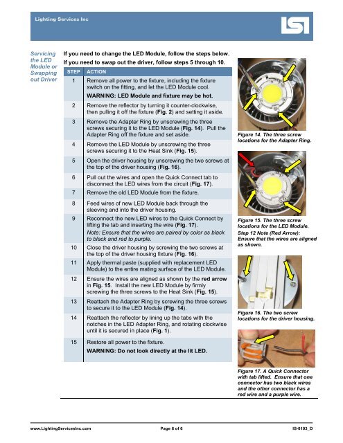
Servicingthe LEDModule orSwappingout DriverIf you need to change the LED Module, follow the steps below.If you need to swap out the driver, follow steps 5 through 10.STEP ACTION1 Remove all power to the fixture, including the fixtureswitch on the fitting, and let the LED Module cool.WARNING: LED Module and fixture may be hot.2 Remove the reflector by turning it counter-clockwise,then pulling it off the fixture (Fig. 2) and setting it aside.3 Remove the Adapter Ring by unscrewing the threescrews securing it to the LED Module (Fig. 14). Pull theAdapter Ring off the fixture and set aside.4 Remove the LED Module by unscrewing the threescrews securing it to the Heat Sink (Fig. 15).5 Open the driver housing by unscrewing the two screws atthe top of the driver housing (Fig. 16).6 Pull out the wires and open the Quick Connect tab todisconnect the LED wires from the circuit (Fig. 17).7 Remove the old LED Module from the fixture.8 Feed wires of new LED Module back through thesleeving and into the driver housing.9 Reconnect the new LED wires to the Quick Connect bylifting the tab and inserting the wire (Fig. 17).Note: Ensure that the wires are paired by color as blackto black and red to purple.10 Close the driver housing by screwing the two screws atthe top of the driver housing fixture (Fig. 16).11 Apply thermal paste (supplied with replacement LEDModule) to the entire mating surface of the LED Module.12 Ensure the wires are aligned as shown by the red arrowin Fig. 15. Install the new LED Module by firmlyscrewing the three screws to the Heat Sink (Fig. 15).13 Reattach the Adapter Ring by screwing the three screwsto secure it to the LED Module (Fig. 14).14 Reattach the reflector by lining up the tabs with thenotches in the LED Adapter Ring, and rotating clockwiseuntil it is secured in place (Fig. 1).15 Restore all power to the fixture.WARNING: Do not look directly at the lit LED.Figure 14. The three screwlocations for the Adapter Ring.Figure 15. The three screwlocations for the LED Module.Step 12 Note (Red Arrow):Ensure that the wires are alignedas shown.Figure 16. The two screwlocations for the driver housing.Figure 17. A Quick Connectorwith tab lifted. Ensure that oneconnector has two black wiresand the other connector has ared wire and a purple wire.www.LightingServicesInc.com Page 6 of 6 IS-0103_D