IRAPE DAM ABSTRACT
IRAPE DAM ABSTRACT
IRAPE DAM ABSTRACT

Create successful ePaper yourself
Turn your PDF publications into a flip-book with our unique Google optimized e-Paper software.
INTRODUCTION<br />
<strong>IRAPE</strong> <strong>DAM</strong><br />
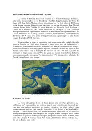
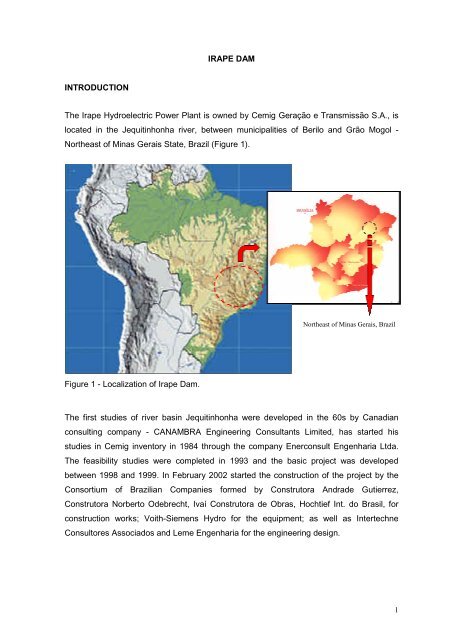
The Irape Hydroelectric Power Plant is owned by Cemig Geração e Transmissão S.A., is<br />
located in the Jequitinhonha river, between municipalities of Berilo and Grão Mogol -<br />
Northeast of Minas Gerais State, Brazil (Figure 1).<br />
Figure 1 - Localization of Irape Dam.<br />
The first studies of river basin Jequitinhonha were developed in the 60s by Canadian<br />
consulting company - CANAMBRA Engineering Consultants Limited, has started his<br />
studies in Cemig inventory in 1984 through the company Enerconsult Engenharia Ltda.<br />
The feasibility studies were completed in 1993 and the basic project was developed<br />
between 1998 and 1999. In February 2002 started the construction of the project by the<br />
Consortium of Brazilian Companies formed by Construtora Andrade Gutierrez,<br />
Construtora Norberto Odebrecht, Ivaí Construtora de Obras, Hochtief Int. do Brasil, for<br />
construction works; Voith-Siemens Hydro for the equipment; as well as Intertechne<br />
Consultores Associados and Leme Engenharia for the engineering design.<br />
Northeast of Minas Gerais, Brazil<br />
1
This is a large undertaking, presenting a rockfill dam with clay core and maximum height<br />
of 208 m - the highest in Brazil (Figure 2), located in a place of very rugged topography,<br />
the type canyon with difficulties constructive associated with topographical aspects and<br />
local geochemical conditions.<br />
Figure 2 - View of Irape Dam.<br />
The plant is in operation since July 20, 2006, with installed capacity of 399 MW to produce<br />
1,807,188 MWh per year of firm energy.<br />
PROJECT LAYOUT<br />
Figures 3 e 4 shows the layout of the main structures. Main features are:<br />
2
Figure 3 - General Lay-out.<br />
Figure 4 - Picture of the General Lay-out.<br />
3
- Two 14m-diameter diversion tunnels, the lower one with an underground control<br />
structure accessed by a shaft and a length of 1227 m, and the upper one uncontrolled<br />
with a length of 1067 m.<br />
- A rockfill dam with clay and gravel core, 208-m high and volume of 10.300.000 m³<br />
(Figure 5);<br />
- Two 12m-diameter spillway tunnels with external structures for controlling gates<br />
(discharge capacity of 4000 m 3 /s), and two underground chutes, 634-m long, discharging<br />
into the river issuing from a flip bucket located 70 m above the stilling basin (Figures 6 and<br />
7);<br />
- One emergency mid-height outlet, with a structure for radial gates, 2.000 m 3 /s discharge<br />
capacity, also with an underground chute;<br />
- A power plant with three power tunnels, an external powerhouse for three Francis<br />
turbines.<br />
(1) Clay core<br />
(2) Filter (Natural sand)<br />
(2A) Filter (Crushed sand) (*)<br />
(3) Fine transition (*)<br />
(3A) Medium transition (*)<br />
(3B) Clayey gravel<br />
(4) Coarse transition (*)<br />
(4B) Fine rockfill (Φ
(1) Underground chute<br />
(2) Spillway structure<br />
(3) Flip bucket<br />
(4) Stilling basin<br />
Figure 7 - Picture of the output the Spillway.<br />
Figure 6 - Spillway chute.<br />
(5) Aeration structures<br />
(6) Ground surface<br />
(7) Weathered rock surface<br />
(8) Slightly weathered to sound rock<br />
5
PROJECT CONDITIONING FACTORS<br />
The Project conditioning factors resulted chiefly from the topographic and geologic<br />
characteristics of the site, and of course from the requirement of a 40-month schedule for<br />
initial energy generation and the costs limitation to render the project economically viable.<br />
The main controlling feature was the necessity to adjust design of structures and<br />
construction activities to the well-defined seasonality of the river.<br />
Topography<br />
The region has a flat erosion surface deeply entrenched by river erosion. At the site the<br />
result was a narrow canyon with almost vertical side walls, about 80 - 100 m wide and 80<br />
m deep, a narrow flat bottom and an additional river channel about 30 m deep and 20 m<br />
wide (Figure 8). The name IR-A-PÉ, (“going on foot” in Portuguese) so it goes, comes<br />
from the fact that the only way to get to the bottom of the valley was by walking down the<br />
steep slopes.<br />
(1) Ground surface<br />
(2) Weathered rock surface<br />
(3) Slightly weathered to sound rock<br />
(4) Core foundation (design)<br />
(5) Core foundation (as built)<br />
(6) Concrete block<br />
Figure 8 - Valley cross-section through the clay core and concrete block.<br />
6
The topographical configuration caused serious problems of access, large volumes of<br />
excavation under very difficult conditions as well as problems for stockpiling and re-<br />
handling construction material. The 208-m high dam with a very tight construction<br />
schedule in a very narrow valley with steep abutments generated problems to reach, trim,<br />
clean and treat the foundations, to place and compact a complex zoning of different<br />
materials and involved design and construction care to minimize arching effects.<br />
Geology<br />
The site has a bedrock of hard quartz mica schists, with good foundation and excavation<br />
conditions, for both surface and underground work, when fresh. Topsoil is moderate to<br />
thin, but the zone of weathered rock is usually thick and irregular. Sub-vertical stress relief<br />
joints with soil-like infillings affected the excavations to the sound rock surface under the<br />
dam core.<br />
The main geological characteristic, however, was the occurrence of sulfides in the rock -<br />
chiefly pyrite and pyrrhotite - in percentages higher then normal and that affected the<br />
initial studies. A realistic assessment of the seriousness of the issue involved studies<br />
carried out by CEMIG, the concrete laboratory of Furnas, the University of Minas Gerais<br />
and a special Board of Consultants on Concrete Deterioration defined how to cope with<br />
the problem, but the adoption of unusual design and construction care was still necessary.<br />
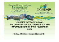
<strong>DAM</strong> - DESIGN AND CONSTRUCTION<br />
The dam is a rockfill structure with a earth core. Its maximum section is shown in Figure 5,<br />
which also shows the complex zoning, the materials used and the concrete block built at<br />
the bottom of the lower channel. The main factors that conditioned and presided over the<br />
final design were:<br />
- canyon-like topography of the valley;<br />
- effects of the sulfides;<br />
- materials available;<br />
- very tight construction schedule.<br />
7
In the region of the dam the valley has a flat erosion surface deeply carved by the river<br />
erosion. This resulted in a narrow canyon with almost vertical side walls, about 80 - 100 m<br />
wide and 80 m deep, a narrow flat bottom and an additional river channel about 30 m<br />
deep and 20 m wide (Figure 8).<br />
The valley shape, besides creating obvious difficulties to access its lower portion to treat<br />
the foundation and place and compact the initial rockfill, posed two main factors: (1) the<br />
occurrence of earth or laterite-infilled sub-vertical stress-relief joints that required deep<br />
excavation to reach sound rock, and (2) the serious arching effects in the dam core<br />
eventually produced by the narrowness of the valley. Figure 9 depicts a cross section of<br />
the valley along the centre-line of the cut-off excavated to sound rock under the<br />
impervious core. It shows the original topography and the trimming of the core foundation<br />
required to eliminate the stress-relief joints and minimize arching problems. It also shows<br />
the concrete block built to help expedite construction work out of the deep channel and<br />
also to reduce arching effect.<br />
Figure 9 - Picture of the excavated canyon in the region of the clay core.<br />
8
The presence of sulfides and aggressive waters also affected the design and construction<br />
features of the dam. The presence of sulfides in the rockfill materials were not considered<br />
as damaging due to the lack of oxygen in the water needed to produce expansive<br />
minerals and disintegration effects. Most of the water coming from the reservoir will have<br />
a low average amount of sulfates and only the concentration of these materials at the<br />
bottom of the reservoir, at the upstream toe of the dam has to be considered. Thus, the<br />
concrete block built at the bottom of the channel had to be protected against the<br />
aggressive waters, and this had to be considered when treating with dental concrete the<br />
irregularities of the foundation. The concrete block under the core was only moderately<br />
extent, but was improved at the bottom to reduce the seepage of aggressive waters<br />
through the foundation. Along with the adoption of measures related to the composition of<br />
the concrete, like the use of ultrafine sulphate resistant cement with low W/C ratios and<br />
microsilica, the concrete block surfaces were waterproofed to avoid contact of the<br />
aggressive water, using an epoxy-based membrane (Figure 10).<br />
Figure 10 - Picture of concrete block surface showing waterproofing membrane.<br />
9
An additional problem was the lack of adequate materials in quantity and quality<br />
consistent with the design requirements. Figure 5 shows the complex zoning adopted to<br />
maximize the use of the material from the required excavation and nearby deposits. For<br />
the rockfill, after extensive investigation and analyses the use of sulfide rock in various<br />
weathering, states was allowed. Non-sulfide rocks from a quarry located at about 5 km<br />
away from the dam were limited to drain, filters, transition materials and some external<br />
slopes such as the upstream shell, in the reservoir fluctuation level zone, and in a<br />
protection layer on the downstream slope. As shown in Figure 5, 3B core material is a<br />
gravel-earth used up to elevation 407.0 m to increase its deformation modulus. The lack<br />
of proper materials made it necessary to mix sandy-clayey soils from near-by deposits<br />
and gravely materials in a soil batching plant.<br />
The dam core was built with sandy-clay with the precaution to use a mixture of gravel and<br />
clay in the deep channels, to get higher rigidity modulus in this zone [1], [2] and [3]. A<br />
layer of more plastic, self-healing soil was placed along the clay/rock contact on the valley<br />
walls to help the redistribution of stresses.<br />
Natural sand was used in the fine filters, and crushed rock in the coarse filters and<br />
transitions. Based on what was observed in the finer fractions of the sulfide-rich rock<br />
excavated from the exploratory addict, only non-sulfide or sulfide-poor rocks were used in<br />
the transitions, brought from the quarry for concrete aggregate.<br />
The tight construction schedule and the strict economic limitations of the job, made<br />
obligatory the use of the excavated materials in the dam embankment, including large<br />
amounts of weathered sulfide-rich rocks. Consequently, with the exception of materials 7<br />
and 9, which were made of non-sulfide or sulfide-poor rocks, all the other embankment<br />
materials came from the required excavations.<br />
This was decided after carrying out several experimental fills and investigating the rockfill<br />
deposits of different ages, as well as the water seeping through the rock mass or the<br />
weathered wastes and embankments. See figure 5 concerning the following comments.<br />
10
Material type 6 is made up of sound or slightly weathered, sulfide-rich rocks and was<br />
placed in 0,80 m thick layers. The amount and type of sulfides had to considered in the<br />
use and positioning of this and other rockfill materials, taking into account the possible<br />
generation of acid effluents, able to concentrate in the bottom of the reservoir or seep<br />
downstream. For this reason, this material was used in the upstream shell, below El.<br />
470,00, in the zone to remain permanently underwater, in a reducing medium, poor in<br />
oxygen and not able to affect the primary rock sulfides and produce excessive amounts of<br />
acids.<br />
Material 5L, placed between the upstream shell and the clay core, is an unconventional<br />
type of material - a saprolite with decomposed rock fragments, well graded, CU around<br />
140 to 160, void ratio of 0.26 to 0.31 (for a rock density of 27kN/m³), which yielded, by<br />
compaction, very high deformability moduli and very low permeabilities. The amount of<br />
sulfides was limited to 0,1%, a requirement that implied detailed control of the stock-piles<br />
and the liberation of its use based on collecting and testing numerous samples. Being of<br />
very low permeability, this material acted as well as an upstream enlargement of the clay<br />
core. Material 2A, used immediately upstream of the core, is a fine sandy-silty residue of<br />
the crushing of sulfide-poor rocks, of low cost, used to clog occasional fractures in the clay<br />
core.<br />
Materials 5 and 5A are, respectively, slightly to medium weathered rockfill and medium to<br />
highly weathered rockfill, rich in fines and containing secondary sulfur minerals. The 5A<br />
material was placed downstream of the filters, between the 5 material and the outer shell<br />
of material 6. In test fills, those materials gave adequate mechanical parameters, with very<br />
low void rations, around 0,18 and quite high deformability moduli, near 80 MPa, but<br />
usually showed quite striking effects due to the sulfur oxides: yellow staining,<br />
efflorescence and heating. Since those materials were located downstream of the core,<br />
they were kept essentially dry. However, to reduce the amount of rain water seeping into<br />
this downstream zone, and prevent the production of acid effluents, a sort of “umbrella”<br />
was provided in the downstream slope, made up of 6 m wide sheets of HDPE (high<br />
density polyethylene), placed each 2,4 m in height, as shown in figures 10 and 11.<br />
11
Figure 10 - Detail of the “umbrella” protection against inflow of rainwater in the<br />
downstream slope of the dam.<br />
Figure 11 - Picture of HDPE (high density polyethylene).<br />
12
To meet the very tight construction schedule, very high productions rates (up to 1.250.000<br />
m³/ month of embankment materials) and some less usual construction procedures were<br />
required. For instance, to get to the height required to start reservoir impounding, El.<br />
475.00, a downstream zone of varied width (min. 30 m) was left to be raised after this<br />
height was reached. Some additional cares were adopted during construction, as well,<br />
such has a zone of fine sand in the upstream face of the core, to help clog occasional<br />
seepage paths of aggressive waters trough core and foundation. Figure 12 shows<br />
downstream slope of Irape Dam.<br />
Figure 12 - Picture of downstream slope of Irape Dam.<br />
13