
You also want an ePaper? Increase the reach of your titles
YUMPU automatically turns print PDFs into web optimized ePapers that Google loves.
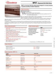
<strong>IGTM</strong> <strong>Gas</strong> <strong>Turbine</strong> <strong>Meter</strong>with electronic outputs and mechanical counterDocumentation and Technical Specifications<strong>Gas</strong> - MeasurementNew size available:DN 400 (16“) G 6500Please inquire!
GeneralThe vemm tec <strong>IGTM</strong> (International <strong>Gas</strong> <strong>Turbine</strong> <strong>Meter</strong>) is ahighly accurate flow meter, approved for custody transfermeasurement, equipped with electronic pulse outputs anda mechanical counter. This document explains the dimensions,ranges, performance, calibration and outputs of theinstrument. It details the installation, safety requirementsand material specifications.The <strong>IGTM</strong> measures gas volume flowing through an annularpassage in the meter. The flowing gas volume is totalisedon a local mechanical counter. In addition, low or highfrequency pulse signals are generated to infer the gas flowand volume. The indicated gas volume is the actual volumeflowing through the meter at the actual temperature andpressure. The <strong>IGTM</strong> is available in two models: CT and IM.The <strong>IGTM</strong>-CT is used for high accuracy and custody transferapplications. The <strong>IGTM</strong>-IM is an economically priced meterwith a good accuracy.OperationThe operation of the International <strong>Gas</strong> <strong>Turbine</strong> <strong>Meter</strong> isbased on the measurement of the velocity of gas. The flowinggas is accelerated and conditioned by the meter´sstraightening section. The straightening vanes prepare thegas flow profile by removing undesired swirl, turbulenceand asymmetry before the gas flows to the turbine wheel.The dynamic forces of the flowing fluid cause the rotor torotate. The turbine wheel is mounted on the main shaft,with special high precision, low friction ball bearings. Theturbine wheel has helical blades that have a known anglerelative to the gas flow. The conditioned and acceleratedgas drives the turbine wheel with an angular velocity that isproportional with the gas velocity.The rotating turbine wheel drives the index head with theeight digit mechanical counter via shafts and gears.The volume and flow rate can also be indicated electronically.A proximity probe generates a signal at each passingblade of the turbine wheel. With the device-specific K-factorand the number of pulses the passed volume can be calculated.With the measured frequency the flow rate can bedetermined.2
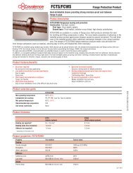
Picture 2 shows this relationship.= Min. flow rate at actual pressure [m 3 /h]= Min. flow rate as specified (table 3) [m 3 /h]= Density of air at standard conditions [1.293 kg/m 3 ]= <strong>Gas</strong> density at standard conditions (table 1) [kg/m 3 ]= Atmospheric pressure [1.013 bar]= Actual pressure at operating conditions [bar abs]Pressure LossThe pressure loss at actual flow and pressure can be calculatedusing the values from the table and the following formula.The pressure loss in ambient air is an importantdesign parameter of the <strong>IGTM</strong>. The pressure loss is minimizedas a result of the design of the internal flow conditionerand the shape of the channels upstream and downstreamof the turbine wheel.= Pressure loss at flowing conditions [mbar]= Pressure loss with ambient air (table 3) [mbar]= Actual density at operating conditions [kg/m 3 ]= Density of air at standard conditions [1.293 kg/m 3 ]= Actual flow rate [m 3 /h]= Maximum flow rate of meter (table 3)[m 3 /h]Operating Range (1:X)<strong>Gas</strong> TypesThe <strong>IGTM</strong> in its standard design can be used for all nonaggressivegases, such as natural gas, methane, propane,butane, city gas and fabricated gas, air, nitrogen, etc.For aggressive gases, like sour gas, biogas and oxygen, specialdesigns are available with Teflon coating, special lubricationor special purging. See table 1, for detailed requirementsfor different type of gases.Material of ConstructionOperating pressure [bar abs]The materials of construction are listed in the table below.Picture 2Example: At 28 bar the operating range improved from1:20 to 1:80OverloadThe <strong>IGTM</strong> is designed to deal with over-ranging of at least20% of Q max . Any over-ranging must occur slowly and withoutpulsations.Temperature RangesAs standard the <strong>IGTM</strong> is designed to operate at temperaturesbetween -10°C to 60°C. Special low and high temperaturedesigns are available on request.PartHousingStraightening Vane<strong>Turbine</strong> Wheel<strong>Meter</strong>ing InsertBearing BlockBearingsShaftsGearsMagnetic CouplingIndex HeadMaterialDuctile Iron (EN-GJS-400-18-LT)Carbon Steel (Cast or Welded)Stainless Steel (on request)AluminiumAluminiumAluminiumAluminiumStainless SteelStainless SteelStainless Steel or Synthetic MaterialStainless SteelAluminium4
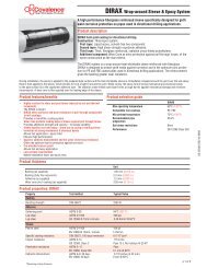
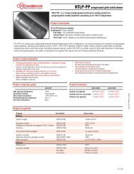
Index HeadThe standard index head can be equipped with the followingoptions:· Tropical version with ventilation· IP 67 with silica gel· High gas temperature version· Special coating for aggressive environments.The index head can be turned through 350° without violatingthe lead seal. An 8-digit non-resettable display showsthe totalized volume. During the initial verification and calibrationtest the ratio of the adjustment gears is checkedand (if necessary) adjusted.Dependent on meter size one revolution of the last righthand wheel of the rolls of the index head can represent 0.1,1 or 10 m 3 . As standard, the index head is equipped withone low frequency Reed (contact closure) switch (1R1) thatgives one pulse at one revolution of the last wheel of thecounter.As an option a Reed switch (1R10) can be provided thatgives 10 pulses per one revolution of the last wheel of thecounter. Every Reed switch is connected in series with a100.0 Ohm resistance. A maximum of two Reed switchescan be provided per meter.In the index head also one high frequency sensor (HF3) isprovided as standard. This proximity sensor provides amiddle-high frequency signal generated by a rotatingimpulse-disk. The signal is intrinsically safe in accordancewith the NAMUR (EN 50227) standard for intrinsically safesignals. A second (similar) sensor (HF4) can be installed inthe index head as an option.By installing optional HF sensors in the meter body, it is possibleto sense each passing blade of the turbine wheel (HF1)and/or of the reference wheel (HF2). The detection is basedon special proximity switches. The signal is intrinsically safein accordance with NAMUR (EN 50227). The interface barriersbetween hazardous area and safe area must be suitablefor the application and are available on request.The vemm tec <strong>IGTM</strong> can be equipped with HF1/HF2 sensorsonly, without an index head. This option requires anelectronic counter, a flow converter or a flow computer, toindicate actual and converted volume. For custody transferpurposes however, the index head is often a mandatoryrequirement.The following options can be offered for pulse outputs.Code Description Max. frequency * Remarks1R1, 2R1 Reed switch < 1 Hz 1R1 standard, 2R1 optional **1R10, 2R10 Reed switch, freq. x 10 < 10 Hz 1R10 and/or 2R10 optional **HF3, HF4 HF NAMUR sensor < 200 Hz HF3 standard, HF4 Optional(in the index head)HF1 HF NAMUR sensor < 4.5 kHz Optional(at the turbine wheel)HF2 HF NAMUR sensor < 4.5 kHz Optional (only for <strong>IGTM</strong>-CT sizes(at the reference wheel) (equal to HF1) 100mm (4") and up)*) Maximum pulse frequency depends on meter size: please refer to table 3**) A maximum of 2 reed switches can be supplied per meter8 digit mechanicalindexHF sensorturbinewheelbearingblockmeteringcartridgestraighteningvanehousingpressure tappinglubrication system5
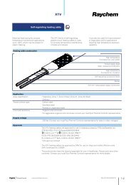
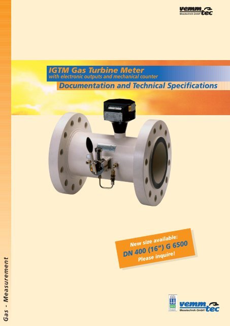
<strong>IGTM</strong> <strong>Gas</strong> <strong>Turbine</strong> <strong>Meter</strong>D E1 G E2 FA B1 B2 C1 C2 C3 C4A Pressure containing meter housing with end-flangesB Flow deflector (straightening vane)B1 Central coneB2 Guiding vanesC <strong>Meter</strong>ing insert cartridge with turbine wheelC1 <strong>Turbine</strong> wheelC2 Precision BearingsC3 Bearing blockC4 Internal gears, shafts and axisD Magnetic coupling (gas tight sealed)E Index head with nameplatesE1 Mechanical counterE2 Connector for Pulse transmitters [1R1; HF3 + options]F Oil PumpG High Frequency pulse transmitters [HF1; HF2]6
Lubrication SystemEach <strong>IGTM</strong> is standard equipped with a lubrication system.The oil pump is dimensioned according to the size of themeter.To achieve the long life of the <strong>IGTM</strong>, regular lubrication isrequired. Typically, for clean gas applications, a 3-monthinterval between two lubrication services is recommended.Dirty gas requires a more frequent lubrication.As an option the <strong>IGTM</strong> can be provided with lifetime lubricatedbearings.Surface Treatment and PaintingBefore applying a corrosion-protective layer, each ductileiron <strong>IGTM</strong> meter body is shot blasted SA 2.5. Carbon steelbodies are mechanically treated. The standard color of themeter body is white (RAL 9001). Stainless steel bodies aresupplied without coating. The color of the index head isblack.Alternative surface treatments like other colors, special coatingsor zinc treatments are possible on request. These specialtreatments can improve the protection against corrosion.Material and Safety TestsAll <strong>IGTM</strong>s are statically tested in accordance with the appropriatestandards and customer requirements· Hydro test at 1.5 x maximum operating pressure· Air seal test at 1.1 x maximum operating pressure· Material certificate per EN 10204 3.1.B· CE-PED compliance: Directive 97/23/ENA certification package can be ordered as an option.Other tests like MID, TÜV certification, NDT and US testingand others are available on request.DocumentationInstallationNormally the meters are installed with some straight upstreampipe lenght. However, the <strong>IGTM</strong> is equipped with aninternal flow conditioner that takes care that the metermeets the requirements of EN 12261 and OIML R32. Thisallows the meter to be installed with minimum 2D upstreampiping. For optimal performance, however,vemm tec recommends that the upstream section is 5D ormore.Fittings like valves, filters, control valves, reducers, T-pieces,bends, safety shut off valves in the upstream section shouldbe preferably 5D or more from the meter inlet. In thesecases the application of an upstream flow conditionermight be considered. This could be a tube bundle straigtener,straightening vanes, or other designs.The down stream section of the meter should preferably be3D or longer. The temperature probe should be installed inthis section. Optionally a temperature probe can be installedin the meter body.The meter is equipped for horizontal installation as standard.<strong>Meter</strong>s ≤150mm (6") diameter can also be operatedvertically. If required, please indicate vertical use on yourorder.The gas flow must be free from liquids, dust and particles.These can damage the delicate bearings and the rotor. Alsowhen dust collects over time it has an adverse effect on themetering accuracy. Non-clean gases should be filtered witha 5-micron particle filter.Pulsating gas flow and vibrations should be avoided.The meter axis should be identical to the upstream pipingaxis. <strong>Gas</strong>kets immediately upstream of the meter shouldnot protrude.The meters are preferably installed inside. When installedoutside, the meter must be protected from direct sunlightand rain for the best performance.The <strong>IGTM</strong> gas turbine meter comes with an installation,operation and maintenance manual. An installation card isattached to each meter. We recommend that this card stayswith the meter. Calibration certificates and material certificatescan be provided as an option.Depending on the order and the meter chosen, the optionallyordered certification package contains:· 3.1.B certificate with declaration of conformity· Material certificates for pressure containing parts· Welding test certificates (when applicable)· Pressure test certificate· Calibration certificates (as ordered)· EEx certificates of the HF pulse transmitters7
Additional InstrumentationThe indicated volume will often be converted to volume atbase conditions. Parameters for these conversions might be:• PressureA pressure tapping enables the measurement of the staticpressure near the turbine wheel. The pressure measurementpoint P r (pressure at metering conditions), designated P m inthe latest standards, is located on the meter housing and ismarked. The bore is 3 mm and perpendicular to the wall.Connection with 6 mm stainless (standard) tubing or largeris recommended.• TemperatureThe temperature measurement should preferably be locatedwithin 3 D downstream of the meter. No pressure reducingparts should be located between the temperature deviceand the meter. The temperature should be measured withinthe center third of the pipe.• Actual densityWhen an actual density meter is used, the requirements forthe pressure and temperature should be followed for thelocation of the density meter. The P r point is the source ofthe gas sample for a density meter that should be located3-5 diameters downstream of the gas turbine meter.No devices that can influence the pressure or the temperatureof the gas should be installed between a gas meterand the applicable temperature sensor and/or densitymeter.Flow Converters andAdditional EquipmentVemm tec can provide you with flow converting devices,ranging from a converter with only basic features, to asophisticated computer with features such as curve correction,valve control, gas chromatograph read-out and othercustomer specified functions.We can also provide you with the additional equipmentsuch as IS-barriers, F/I-converters, transmitters, filters,straightening vanes and meter tubes.We will be happy to send you any further information.SystemsVemm tec has many years of experience with meteringskids such as provers or pressure reduction stations. At yourrequest we will be happy to offer meter runs and integratedsystems.Ordering InformationIn order to quickly process your enquiry, we need the followinginformation for adequate pricing and sizing:· Nominal pipe size in mm or inches for installing the meter· Model: High accurate custody transfer type (CT) or industrialmodel (IM)· Body material: Ductile iron, carbon steel or stainless steel· Flow rate: Maximum, minimum (actual or standard cubicmeter per hour, please specify); or G-size.· Pressure: Maximum, minimum and normal operatingpressure· Temperature: Maximum, minimum and normal operatingtemperature· <strong>Gas</strong> type, composition or analysis (if available)· Relative density or base density (standard conditions)· Flange connection, pressure rating and face type· Output signals required (LF reed switch, HF at index heador HF at turbine wheel, dual pulse output)· Installation conditions (Indoor-Outdoor, ambient conditions)· Flow direction horizontal (left-right; right-left) or vertical(up-down; down-up)· Optional services and additional equipment required (calibrations,barriers, flow correctors, filters, meter tubes)Alternatively you can ask for our <strong>IGTM</strong> questionnaire.8
Table 1<strong>Gas</strong> type<strong>Gas</strong> type Symbol Density <strong>Meter</strong> housing Notes@1.013 bar[kg/m 3 ]Acetylene C 2 H 4 1.17 Special Aluminium parts Teflon coatedAir 1.29 StandardAmmonia NH 3 0.77 Standard O-Rings / LubricationArgon Ar 1.78 StandardBiogas Special Special InternalButane C 4 H 10 2.70 StandardCarbon dioxide CO 2 1.98 Standard Except foodstuff industryCarbon monoxide CO 1.25 StandardCity gasStandardEthane C 2 H 6 1.36 StandardEthylene (gas phase) C 2 H 4 1.26 Standard Special InternalFlue gases Special O-Rings / LubricationFreon (gas phase) CCl 2 F 2 5.66 Standard O-Rings / LubricationHelium He 0.18 Standard Special flow rangeHydrogen H 2 0.09 Special Special flow rangeHydrogen sulphur (0.2%) H 2 S 1.54 Special Special InternalMethane CH 4 0.72 StandardNatural <strong>Gas</strong> 0.8 StandardNitrogen N 2 1.25 StandardOxygen (pure) O 2 1.43 Standard Special InternalPentane C 5 H 12 3.46 StandardPropane C 3 H 8 2.02 StandardPropylene (gas phase) C 3 H 6 1.92 Standard Special InternalSour gas Special O-Rings / LubricationSulphur dioxide (0.2%) SO 2 2.93 Special Special Internal9
Table 2.2Dimensions and weightsDN Size A B E D Height Total length Pressure Body Weight[mm] G [mm] [mm] [mm] [mm] H [mm] L [mm] class material [kg][Inch] CT IM CT IM CT IM CT IM CT IM PN or ANSI CT IMDN 400 182 56 218 85 198 235 285 255 275 450 175 PN 10/16 Ductile Iron 45 30150 or 215 230 285 250 260 PN 10/16 Steel 45 62(6") 650 215 240 300 250 270 PN 25/40 Steel 40 70or 215 250 345 250 290 PN 64 Steel 74 1021000 215 250 355 250 290 PN 100 Steel 90 110198 235 279 255 275 ANSI 150 Ductile Iron 50 30215 225 279 250 260 ANSI 150 Steel 50 60215 240 318 250 275 ANSI 300 Steel 70 84215 240 318 250 275 ANSI 400 Steel 80 84215 255 356 250 290 ANSI 600 Steel 100 110DN 650 240 69 278 160 250 255 340 270 290 600 200 PN 10 Ductile Iron 75 92200 or 255 340 290 PN 10 Steel 75 92(8") 1000 255 340 290 PN 16 Ductile Iron 75 92or 255 340 290 PN 16 Steel 75 921600 265 360 298 PN 25 Steel 90 108275 375 308 PN 40 Steel 100 122285 415 320 PN 64 Steel 125 163290 430 330 PN 100 Steel 160 176255 343 290 ANSI 150 Ductile Iron 96 96255 343 290 ANSI 150 Steel 96 96275 381 308 ANSI 300 Steel 120 128275 381 308 ANSI 400 Steel 135 128285 419 320 ANSI 600 Steel 155 190DN 1000 300 125 353 168 270 270 395 285 285 750 300 PN 10 Steel 90 70250 or 405 PN 16 Steel 95 72(10") 1600 425 PN 25 Steel 110 90or 450 PN 40 Steel 130 1082500 470 PN 64 Steel 155 140505 PN 100 Steel 220 205406 ANSI 150 Steel 110 72445 ANSI 300 Steel 150 110445 ANSI 400 Steel 170 122508 ANSI 600 Steel 240 210DN 1600 360 130 358 130 315 315 445 320 320 900 320 PN 10 Steel 120 90300 or 460 PN 16 Steel 130 100(12") 2500 485 PN 25 Steel 150 124or 515 PN 40 Steel 180 1604000 530 PN 64 Steel 240 180585 PN100 Steel 345 280483 ANSI 150 Steel 160 160521 ANSI 300 Steel 210 212521 ANSI 400 Steel 240 235559 ANSI 600 Steel 290 300DN 2500 480 150 480 150 350 350 565 355 355 1200 400 PN 10 Steel 355 225400 or 580 PN 16 Steel 380 250(16") 4000 620 PN 25 Steel 415 285or 660 PN 40 Steel 455 3256500 670 PN 64 Steel 500 370715 PN100 Steel 600 470597 ANSI 150 Steel 410 280648 ANSI 300 Steel 450 320648 ANSI 400 Steel 500 370686 ANSI 600 Steel 590 46011
Table 3<strong>IGTM</strong> gas turbine meter: technical specificationsThe indicated frequency values and k-factors of HF1/HF2 and HF3/HF4 are forinformation only. The final values will be mentioned at the meter´s nameplateand in the calibration certificate.<strong>Gas</strong> - Measurementvemm tec Messtechnik GmbHGartenstrasse 2014482 Potsdam-BabelsbergGermanyTel. +49 (0) 3 31 / 70 96 274Fax +49 (0) 3 31/7096270E mail: info@vemmtec.comInternet: http://www.vemmtec.comNominal Size Q max Q min Rotating Max. Max. Max. k-factor k-factor k-factordiameter rating (standard speed <strong>Turbine</strong> wheel frequency frequency frequencyflow range) turbine wheel HF1/HF2 HF3/HF4 1R1 HF1/HF2 HF3/HF4 1R1[mm] @ Q max blade number approx. approx. Reed approx. approx. Reed[inch] G [m 3 /h] [m 3 /h] [min-1] angle of blades [Hz] [Hz] [Hz] [Imp/m 3 ] [Imp/m 3 ] [Imp/m 3 ]DN 50 G 40 65 13 8900 45 16 2800 80 0,18 155000 4400 10(2”) G 65 100 10 13700 45 16 4300 120 0,28 155000 4400 10DN 80 G 100 160 16 6200 45 16 1900 50 0,04 42200 1200 1(3”) G 160 250 13 9600 45 16 2900 80 0,07 42200 1200 1G 250 400 20 8900 30 16 2600 70 0,11 23500 670 1DN 100 G 160 250 13 4300 45 16 1200 60 0,07 17000 800 1(4”) G 250 400 20 6900 45 16 1900 90 0,11 17000 800 1G 400 650 32 6500 30 16 1700 80 0,18 9400 440 1DN 150 G 400 650 32 3400 45 20 1100 70 0,18 6280 360 1(6”) G 650 1000 50 5200 45 20 1700 100 0,28 6280 360 1G 1000 1600 80 4800 30 20 1600 60 0,04 3570 135 0,1DN 200 G 650 1000 50 2200 45 20 790 40 0,03 2840 150 0,1(8”) G 1000 1600 80 3500 45 20 1300 70 0,04 2840 150 0,1G 1600 2500 130 3100 30 20 1100 60 0,07 1510 80 0,1DN 250 G 1000 1600 80 2000 45 24 830 60 0,04 1870 135 0,1(10”) G 1600 2500 130 3100 45 24 1300 90 0,07 1870 135 0,1G 2500 4000 200 2900 30 24 1200 90 0,11 1110 80 0,1DN 300 G 1600 2500 130 1900 45 24 780 60 0,07 1120 80 0,1(12”) G 2500 4000 200 3000 45 24 1300 90 0,11 1120 80 0,1G 4000 6500 320 2800 30 24 1200 130 0,18 660 75 0,1DN 400 G 2500 4000 200 1600 45 24 610 60 0,11 550 55 0,1(16”) G 4000 6500 320 2600 45 24 990 100 0,18 550 55 0,1G 6500 10000 500 2300 30 24 1300 130 0,28 470 50 0,1200–002–003 Changes in course of technical development are reserved. Jan. 2007