Guidance on DNV's DRILL notation
Guidance on DNV's DRILL notation
Guidance on DNV's DRILL notation
- No tags were found...

You also want an ePaper? Increase the reach of your titles
YUMPU automatically turns print PDFs into web optimized ePapers that Google loves.
<str<strong>on</strong>g>Guidance</str<strong>on</strong>g> <strong>on</strong> DNV’s <strong>DRILL</strong> notati<strong>on</strong>Offshore Technical <str<strong>on</strong>g>Guidance</str<strong>on</strong>g> OTG-07, September 2012
OFFSHORE TECHNICAL GUIDANCE1 Introducti<strong>on</strong> ............................................................................................................................................... 21.1 Introducti<strong>on</strong> ...................................................................................................................................... 21.2 Objective ........................................................................................................................................... 21.3 Scope ................................................................................................................................................. 21.4 References ......................................................................................................................................... 31.5 Definiti<strong>on</strong>s and abbreviati<strong>on</strong>s ........................................................................................................... 31.6 Structure of document ...................................................................................................................... 52 Basic principles of class .............................................................................................................................. 62.1 Role and limitati<strong>on</strong>s of classificati<strong>on</strong> ................................................................................................. 62.2 Class in operati<strong>on</strong> .............................................................................................................................. 62.3 System and equipment certificati<strong>on</strong> ................................................................................................. 82.4 Relati<strong>on</strong>ship with other Regulatory Schemes ................................................................................... 93 Survey executi<strong>on</strong> ...................................................................................................................................... 103.1 Introducti<strong>on</strong> .................................................................................................................................... 103.2 The survey process .......................................................................................................................... 103.3 System inspecti<strong>on</strong> and testing ........................................................................................................ 134 Handling of certified equipment .............................................................................................................. 324.1 Equipment repairs and overhauls ................................................................................................... 324.2 Certificati<strong>on</strong> of temporary equipment ............................................................................................ 344.3 Documentati<strong>on</strong> ............................................................................................................................... 35DET NORSKE VERITASPage 1OTG-07
OFFSHORE TECHNICAL GUIDANCE1 INTRODUCTION1.1 INTRODUCTIONThe Offshore Service Specificati<strong>on</strong> DNV-OSS-101 “RULES FOR CLASSIFICATION OF OFFSHORE <strong>DRILL</strong>ING ANDSUPPORT UNITS” c<strong>on</strong>tains DNV’s technical requirements and procedures for obtaining and retainingClassificati<strong>on</strong> for Offshore Drilling and Support Units. It includes a listing of the applicable technical referencesto be applied for classificati<strong>on</strong>.The Offshore Standard DNV-OS-E101 “<strong>DRILL</strong>ING PLANT” c<strong>on</strong>tains criteria, technical requirements and guidance<strong>on</strong> design, c<strong>on</strong>structi<strong>on</strong>, commissi<strong>on</strong>ing and testing of drilling facilities, well interventi<strong>on</strong> facilities andassociated equipment. Units meeting this standard may be awarded the Additi<strong>on</strong>al Class Notati<strong>on</strong> <strong>DRILL</strong>.The technical and procedural requirements of the <strong>DRILL</strong> notati<strong>on</strong> have a clear positive effect <strong>on</strong> safety of theunit and its drilling equipment, while at the same time ensuring clarity and transparency of the documentati<strong>on</strong>of the systems within its scope.1.2 OBJECTIVEThe objective of this document is to increase the understanding of the DNV notati<strong>on</strong> <strong>DRILL</strong>, its scope, objective,procedures and requirements in the operati<strong>on</strong>al phase of a drilling unit. This increased understanding willensure an efficient and effective follow up process to maximize the benefits of the notati<strong>on</strong>.In simple terms:What, How, When and By Whom for compliance with DNV’s <strong>DRILL</strong> notati<strong>on</strong>Figure 1 The objective of this document in simple termsThe readers of this document are foremost those who follow the procedures and requirements as described inOSS-101 and OS-E-101, specifically as they apply to the <strong>DRILL</strong> notati<strong>on</strong>, for example:• Owners/pers<strong>on</strong>nel <strong>on</strong>shore and <strong>on</strong>board resp<strong>on</strong>sible for regulatory compliance• Owners/ pers<strong>on</strong>nel <strong>on</strong>board resp<strong>on</strong>sible for maintenance of equipment• Suppliers of drilling equipment (new and/or refurbished)• DNV surveyors• Other stakeholders (e.g. Flag, Coastal State Authorities)1.3 SCOPEThis document describes <strong>on</strong>ly the follow up of the <strong>DRILL</strong> notati<strong>on</strong> in the operati<strong>on</strong>al phase of a unit. As such itexcludes specific guidance for activities during the building phase and up to delivery of the drilling unit.The document describes both the survey <strong>on</strong> board the unit and the relevant details and procedures for the recertificati<strong>on</strong>of systems. It is to be used in c<strong>on</strong>juncti<strong>on</strong> with the above menti<strong>on</strong>ed OSS-101 and OS-E101together, as a supplementary guidance document.This document does not describes the verificati<strong>on</strong>/ re-certificati<strong>on</strong> requirements and procedures as required bynati<strong>on</strong>al authorities 1 , although what is given here may be used to fulfil their requirements. .1 See also closing paragraphs of secti<strong>on</strong> 2.3DET NORSKE VERITASPage 2OTG-07
OFFSHORE TECHNICAL GUIDANCEFrom a technical perspective the scope of this document covers the following systems:• Drilling related structures• Well c<strong>on</strong>trol systems• Heave compensati<strong>on</strong> and tensi<strong>on</strong>ing systems• Hoisting and rotating systems• BOP and pipe handling systems• Bulk storage, drilling fluid circulati<strong>on</strong> and mixing and cementing• Well testing and associated well c<strong>on</strong>trol system• Other systems (winches, gear transmissi<strong>on</strong>s, manriding equipment).1.4 REFERENCESReference is made to the following DNV standards which are available for free download <strong>on</strong> the DNV websitewww.dnv.com:Offshore Service Specificati<strong>on</strong>DNV-OSS-101 Rules for Classificati<strong>on</strong> of Offshore Drilling and Support UnitsOffshore StandardsDNV-OS-A101 Safety Principles and ArrangementsDNV-OS-B101 Metallic MaterialsDNV-OS-C401 Fabricati<strong>on</strong> and Testing of Offshore StructuresDNV-OS-D101 Marine and Machinery Systems and EquipmentDNV-OS-D201 Electrical Installati<strong>on</strong>sDNV-OS-D202 Automati<strong>on</strong>, Safety, and Telecommunicati<strong>on</strong> SystemsDNV-OS-D301 Fire Protecti<strong>on</strong>DNV-OS-E101 Drilling PlantRecommended PracticesDNV-RP-A201 Plan Approval Documentati<strong>on</strong> Types – Definiti<strong>on</strong>sDNV-RP-E101 Recertificati<strong>on</strong> of Well C<strong>on</strong>trol EquipmentDNV-RP-E102 Recertificati<strong>on</strong> of Blowout Preventers and Well C<strong>on</strong>trol Equipment for the US Outer C<strong>on</strong>tinentalShelfIn additi<strong>on</strong> relevant normative references can be found in Ch. 1 Sec. 1 of both OSS-101 and OS-E1011.5 DEFINITIONS AND ABBREVIATIONSDefiniti<strong>on</strong>sBody testMaintenance: Pressure test of the equipment’s press envelope: General work <strong>on</strong> the equipment typically carried out offshore and usually by the unitcrewDET NORSKE VERITASPage 3OTG-07
OFFSHORE TECHNICAL GUIDANCEPerformance testPressure testOverhaul: Testing of the intended functi<strong>on</strong>ing of a comp<strong>on</strong>ent. Low pressure as well as ratedworking pressure is required. Operators to be tested as well as the main functi<strong>on</strong> itself.: Test, usually hydrostatic but may involve other fluids or gas, to test pressures as per therelevant standards.: Process of restoring and maintaining an equipment, machine, or system in a serviceablec<strong>on</strong>diti<strong>on</strong>. Overhaul involves (1) partial or complete disassembly of the item, (2)inspecti<strong>on</strong> to detect damaged, defective, or worn parts, (3) repair or replacement ofsuch parts, and (4) reassembly, testing, and trial-run prior to returning the item to its fulloperating level. Overhaul does not involve modificati<strong>on</strong>s to the original design.Over-pressure test : also referred to as proof test. With the comp<strong>on</strong>ent completely assembled but notpainted, and internal mechanisms in open positi<strong>on</strong> as applicable, all outlets should beblanked off. The comp<strong>on</strong>ent should then be pressurized to a test pressure asdetermined by the relevant design code, or as specially agreed.RefurbishmentRe-manufacturing: See definiti<strong>on</strong> of overhaul: Total or partial dismantling and weld, repair and/or stress relieving heat treatment, e.g.after rewelding ring grooves, bores etc. of pressure c<strong>on</strong>taining comp<strong>on</strong>ents. Gates ingate valves, flaps in n<strong>on</strong>-return valves, rams in ram type BOP's, annular preventer bagelements or other sealing elements that moves. Pressure energized sealing such as ringgaskets are not classed as dynamic seals.Abbreviati<strong>on</strong>sCVI Close Visual Inspecti<strong>on</strong>DPIIIPLPIMPIMWPNDTPWHTUPSPSVROVIBOPWPDye Penetrant Inspecti<strong>on</strong>In-service Inspecti<strong>on</strong> program. A DNV developed inspecti<strong>on</strong> plan c<strong>on</strong>taining the structural items to besurveyed to satisfy the requirements of main class, excluding any additi<strong>on</strong>al class notati<strong>on</strong>s (note forcolumn stabilized and self-elevating units <strong>on</strong>ly)Liquid Penetrant Inspecti<strong>on</strong> (also known as DPI)Magnetic Particle Inspecti<strong>on</strong>Maximum Work Pressure (maximum pressure for which item is designed)N<strong>on</strong> Destructive TestingPost Weld Heat TreatmentUninterrupted Power SupplyPressure Safety ValveRemote Operated VehicleInternal Blow Out PreventerWorking PressureOther definiti<strong>on</strong>s and abbreviati<strong>on</strong>s can be found in Ch. 1 Sec. 1 of both OSS-101 and OS-E101.DET NORSKE VERITASPage 4OTG-07
OFFSHORE TECHNICAL GUIDANCE1.6 STRUCTURE OF DOCUMENTTo increase a basic understanding of the role of class and as a foundati<strong>on</strong> of the following chapters, thisdocument starts with an introducti<strong>on</strong> to classificati<strong>on</strong>, highlighting the role of class and its limitati<strong>on</strong>s, thesurvey and the certificati<strong>on</strong> process.Chapter 3 thereafter, focuses <strong>on</strong> the survey executi<strong>on</strong>. After a discussi<strong>on</strong> <strong>on</strong> the followed process during thisexecuti<strong>on</strong>, paragraph 3.3 details the specific survey, test and documentati<strong>on</strong> requirements for each specific(sub) system as inside the scope of DNV’s <strong>DRILL</strong> notati<strong>on</strong>.Chapter 4 c<strong>on</strong>tinues with handling of certified equipment, discussing in special equipment repairs andoverhauls, certificati<strong>on</strong> of temporary equipment and documentati<strong>on</strong>.The document c<strong>on</strong>cludes with an Appendix c<strong>on</strong>taining a list of all equipment under a Category I equipmentscheme.DET NORSKE VERITASPage 5OTG-07
OFFSHORE TECHNICAL GUIDANCE2 BASIC PRINCIPLES OF CLASS2.1 ROLE AND LIMITATIONS OF CLASSIFICATIONWhat is classificati<strong>on</strong>Classificati<strong>on</strong> is the definiti<strong>on</strong> of a set of requirements for vessels and systems together with an inspecti<strong>on</strong>regime providing assurance that the requirements are met during the design and c<strong>on</strong>structi<strong>on</strong>, and maintainedduring the operati<strong>on</strong>al life of a vessel or Mobile Offshore Unit (MOU).Relevant requirements for these are dependent <strong>on</strong> specific design and operati<strong>on</strong>al use. Classificati<strong>on</strong> isstructured accordingly and this is identified by notati<strong>on</strong>s. Besides identifying which set of requirements isapplied, these notati<strong>on</strong>s also differentiate between mandatory and voluntary requirements.For the mandatory part, DNV mandates that the requirements and our identified involvement is essential toensure a minimum safety and reliability of the asset, the lives of the pers<strong>on</strong>nel <strong>on</strong>board and the envir<strong>on</strong>ment.As such, the compliance to these is a prerequisite for operating under DNV class. This is an importantfoundati<strong>on</strong> for the worldwide recogniti<strong>on</strong> classificati<strong>on</strong> has gained as representing an adequate level of safetyand quality 2 .The voluntary requirements are bey<strong>on</strong>d the minimum safety and reliability of the asset; either extending thescope of DNV’s involvement or assuring higher safety, reliability level and/ or capability. Being voluntary, it isthe decisi<strong>on</strong> of the owner and his c<strong>on</strong>tract partners to follow these or not.What classificati<strong>on</strong> is notClassificati<strong>on</strong> does not relieve the owner in its resp<strong>on</strong>sibility for safe and reliable operati<strong>on</strong>s, nor hisresp<strong>on</strong>sibility to maintain the vessel/MOU properly.In additi<strong>on</strong>, classificati<strong>on</strong> is not a substitute for the client's own quality and safety c<strong>on</strong>trol and related duties, orthe client's obligati<strong>on</strong>s to third parties, nor to relieve the client of any c<strong>on</strong>sequences of default.Even though there may be some overlap, classificati<strong>on</strong> does not ensure that nati<strong>on</strong>al regulati<strong>on</strong>s are met. Thisapplies in particular for our mandatory notati<strong>on</strong>s aiming at a minimum safety and reliability worldwide. It is<strong>on</strong>ly with certain additi<strong>on</strong>al voluntary notati<strong>on</strong>s and scope that 100% coverage may be achieved.Even with the applicati<strong>on</strong> of these specific nati<strong>on</strong>al notati<strong>on</strong>s, classificati<strong>on</strong> does not imply that the vessel isapproved by the relevant flag state or coastal shelf authorities. It is <strong>on</strong>ly after their acceptance andauthorizati<strong>on</strong> that DNV may issue the relevant certificates <strong>on</strong> their behalf.2.2 CLASS IN OPERATIONSurveysAll units in class are subject to periodical surveys in order to c<strong>on</strong>firm that the hull, machinery, equipment andsystems remain in satisfactory c<strong>on</strong>diti<strong>on</strong> and in compliance with Rules and other mandatory standards. Thesesurveys, by definiti<strong>on</strong> executed by a class surveyor, can be supported by the inspecti<strong>on</strong> results of 3 rd partycompanies or approved service suppliers.2 A sec<strong>on</strong>d element for the recogniti<strong>on</strong> of class is the separati<strong>on</strong> of roles between owner, resp<strong>on</strong>sible formaintenance and operati<strong>on</strong> of the unit within its approved design limitati<strong>on</strong>s, and classificati<strong>on</strong> as independentverifier that the unit is maintained to a Class standard and operated within its approved design limitati<strong>on</strong>s.DET NORSKE VERITASPage 6OTG-07
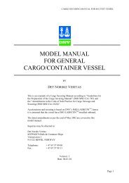
OFFSHORE TECHNICAL GUIDANCEThe scope of the surveys is dependent <strong>on</strong> the vessel characteristics (i.e. vessel shape, its functi<strong>on</strong>, age andsystems <strong>on</strong> board), but also <strong>on</strong> the (selected) involvement of class. The last is identified by the class notati<strong>on</strong>the vessel caries. As a specific example for this guideline, we highlight that the drilling systems and equipmentare <strong>on</strong>ly included in the class survey scope if the vessel carries the <strong>DRILL</strong>-notati<strong>on</strong>. On the other hand; if thevessel does not have the <strong>DRILL</strong> notati<strong>on</strong>, the survey shall not cover the drilling systems and related equipment.The attending surveyor’s focus of attenti<strong>on</strong> <strong>on</strong> the drilling systems and equipment is <strong>on</strong> the “safety-related”and reliability aspects of the drilling systems and equipment. Such systems/equipment generally fall into <strong>on</strong>e ofthe following two categories:• Safety related due to its functi<strong>on</strong>ality (e.g. well c<strong>on</strong>trol equipment);This implies that failure to functi<strong>on</strong> as intended, has a direct effect <strong>on</strong> the unit’s ability to c<strong>on</strong>trol,detect or mitigate against a hazardous situati<strong>on</strong>.• Safety hazard can result as a c<strong>on</strong>sequence of an equipment failure (e.g. lifting appliances).For the <strong>DRILL</strong> notati<strong>on</strong>, the following periodical surveys exist (including their interval between parentheses):• annual survey (interval of <strong>on</strong>e year, with a window of +/- 3 m<strong>on</strong>ths);• complete survey (interval of five years, with a window of -3/-0 m<strong>on</strong>ths).A more detailed descripti<strong>on</strong> of the executi<strong>on</strong> of these surveys is given in Chapter 3.The above traditi<strong>on</strong>al surveys may be replaced by alternative survey arrangements. A comm<strong>on</strong> objective ofthese is to reduce down-time resulting from the normal survey schemes. In additi<strong>on</strong> they may lead to improvedreliability and reducti<strong>on</strong>s in maintenance cost. The figure below gives a short introducti<strong>on</strong> to the alternativearrangements.PMS-RCMThe Planned Maintenance System based <strong>on</strong> Reliability Centered Maintenance Methodology or PMSRCM surveyregime has been introduced in order to reduce down time and increase flexibility for owners who are using an RCMbased preventive maintenance system. The RCM approach will typically also lead to performance improvement,reducti<strong>on</strong>s in maintenance cost and improved reliability.PMS-RCM can be utilized for main class machinery and drilling equipment. The main scope for annual and renewalsurveys is to ensure that the maintenance program is complied with and that the owner is actively utilizing ac<strong>on</strong>tinuous improvement program in order to ensure that the maintenance system is c<strong>on</strong>tinuously optimized.Offshore CMThe Offshore C<strong>on</strong>tinuous M<strong>on</strong>itoring (Offshore CM) survey arrangement allows the vessel owner to replacecalendar based overhauls with c<strong>on</strong>diti<strong>on</strong> m<strong>on</strong>itoring. This will reduce the need for down time due to intrusivesurveys. Generally a CM program will also have a significant c<strong>on</strong>tributi<strong>on</strong> in ensuring higher regularity and reducedmaintenance cost. The survey arrangement is applicable to main class machinery and drilling machinery. It isnecessary to use an approved service provider for the c<strong>on</strong>diti<strong>on</strong> m<strong>on</strong>itoring.Figure 2 Introducti<strong>on</strong> to alternative survey arrangementsC<strong>on</strong>diti<strong>on</strong>s of Class and AuthorityIt is the resp<strong>on</strong>sibility of the Owner to ensure that the unit c<strong>on</strong>tinues to meet the technical standards asdefined by the Rules, and it is the resp<strong>on</strong>sibility of DNV to verify this and in additi<strong>on</strong> to communicate this statusto all relevant stakeholders. This separati<strong>on</strong> of roles is an important foundati<strong>on</strong> for the internati<strong>on</strong>alrecogniti<strong>on</strong> of Class.DET NORSKE VERITASPage 7OTG-07
OFFSHORE TECHNICAL GUIDANCEThe above relati<strong>on</strong>ship requires good and transparent communicati<strong>on</strong>. In additi<strong>on</strong> to the day-to-day dayoperati<strong>on</strong>al communicati<strong>on</strong>s, two formal means of communicati<strong>on</strong> have been defined to communicate thestatus of a unit; C<strong>on</strong>diti<strong>on</strong>s of Class/Authority (CC, respectively CA, depending <strong>on</strong> the deviati<strong>on</strong> as referred toby the C<strong>on</strong>diti<strong>on</strong> are part of Class or Nati<strong>on</strong>al Legislati<strong>on</strong>) and Memorandum to Owner (MO).A detailed descripti<strong>on</strong> of these can be found in DNV Offshore Service Specificati<strong>on</strong>-101, Ch. 1, Sec. 5. Figure 3highlights their structural differences.CC/ CA• deviati<strong>on</strong> fromstandard• requires follow upMO• other suplemental info• no follow up requiredFigure 3 Differences between CC/CA and MOA CC/CA is formal documentati<strong>on</strong> of a deviati<strong>on</strong> from a technical standard found in the Rules or StatutoryRequirements, and requires formal follow up by the Owner. A MO, though formally issued, is used tocommunicate informati<strong>on</strong> to the Owner and does not require formal follow –up by the Owner.2.3 SYSTEM AND EQUIPMENT CERTIFICATIONThe purpose of system and equipment certificati<strong>on</strong> is to:1. defining minimum requirements for the design, material, c<strong>on</strong>structi<strong>on</strong>, testing and commissi<strong>on</strong>ing;2. serve as a reference document in c<strong>on</strong>tractual matters between purchaser and c<strong>on</strong>tractor;3. serve as a guideline for designers, purchasers and c<strong>on</strong>tractors;4. specify procedures and requirements for drilling and well interventi<strong>on</strong> facilities;5. Provide transparency of the system design and quality to involved stakeholders, e.g. charterer,authorities, public.Certificati<strong>on</strong> of certain drilling systems and equipment is mandatory for Class notati<strong>on</strong> <strong>DRILL</strong>. Details of therequired certificati<strong>on</strong> process is given in OS-E101, Ch. 3, the systems involved are listed in Appendix AFigure 4 gives a schematic overview of a certificati<strong>on</strong> process’ basic steps. The follow up of each step in anactual comp<strong>on</strong>ent depends <strong>on</strong> a risk assessment including experience of the manufacturer <strong>on</strong> the comp<strong>on</strong>entunder certificati<strong>on</strong>, its quality c<strong>on</strong>trol system, the complexity of the design etc.Special attenti<strong>on</strong> is drawing to the last box of the figure, ‘Certificate maintenance after delivery’. It is requiredthat certificati<strong>on</strong> is maintained after delivery of the vessel, during its life time. Note in this respect <strong>on</strong> therelati<strong>on</strong> with objective number 5 <strong>on</strong> the beginning of this secti<strong>on</strong>. Chapter 4 discusses in detail howcertificati<strong>on</strong> should be handled after delivery, including implicati<strong>on</strong>s of class transfers and new buildings with alimited class involvement.DET NORSKE VERITASPage 8OTG-07
OFFSHORE TECHNICAL GUIDANCE1. design approval, documented by a design verificati<strong>on</strong> report (DVR) or typeapproval certificate(for existing equipment review of certificates)2. pre-producti<strong>on</strong> meeting prior to the start of fabricati<strong>on</strong>3. survey during fabricati<strong>on</strong>, as applicable(survey scope iaw agreed Inspecti<strong>on</strong> and test plan)4. witness final functi<strong>on</strong>al, pressure and load tests, as applicable5. review of fabricati<strong>on</strong> records6. Certificate maintenance after deliveryFigure 4 Overview of certificati<strong>on</strong> process’ basic stepsClassificati<strong>on</strong> has no requirement for “re-certificati<strong>on</strong>” of equipment. The correct functi<strong>on</strong>ing and maintenanceof the equipment is verified during the renewal survey and by DNV’s involvement during equipment repairsand overhauls. The resulting survey reports document that the certified equipment is maintained andfuncti<strong>on</strong>s according prescribed standards.However, it is recognized that nati<strong>on</strong>al legislati<strong>on</strong> may require a (5-yearly) re-certificati<strong>on</strong>. DNV may providethe certificati<strong>on</strong> services in order to comply with such legislati<strong>on</strong> in additi<strong>on</strong> to its class services.2.4 RELATIONSHIP WITH OTHER REGULATORY SCHEMESThis document <strong>on</strong>ly describes the relevant procedures as follows from classificati<strong>on</strong>. For more informati<strong>on</strong> <strong>on</strong>re-certificati<strong>on</strong> we refer to DNV-RP-E101, Recertificati<strong>on</strong> of Well C<strong>on</strong>trol Equipment, and DNV-RP-E102,Recertificati<strong>on</strong> of Blowout Preventers and Well C<strong>on</strong>trol Equipment for the US Outer C<strong>on</strong>tinental Shelf.DET NORSKE VERITASPage 9OTG-07
OFFSHORE TECHNICAL GUIDANCE3 SURVEY EXECUTION3.1 INTRODUCTIONThis chapter describes the executi<strong>on</strong> of the survey to drilling systems and equipment as covered by the <strong>DRILL</strong>notati<strong>on</strong>. It c<strong>on</strong>sists of two parts. The first describes the survey process and scope, both for the annual andcomplete periodical surveys, and the preparati<strong>on</strong>s required for an efficient executi<strong>on</strong> of the survey.The sec<strong>on</strong>d part describes the inspecti<strong>on</strong>s and tests as part of the surveys, per specific system.3.2 THE SURVEY PROCESSPlanningThe owner is encouraged to communicate with its local DNV stati<strong>on</strong> at least 6 m<strong>on</strong>ths prior to the 4th annualanniversary date, to fully evaluate and understand the upcoming survey.It should be understood the owner can commence the survey 1 year in advance of its anniversary date andmuch of the survey can be c<strong>on</strong>ducted during operati<strong>on</strong>s. Also it should be understood selected equipment mayhave been recently overhauled or replaced; OEM or independent inspecti<strong>on</strong>s could become a factor to reducesome inspecti<strong>on</strong>.It is underlined that the above approach supports a comm<strong>on</strong> evaluati<strong>on</strong> of the unit and eliminates unnecessarydown time.Preparati<strong>on</strong>For a successful and efficient implementati<strong>on</strong> of a <strong>DRILL</strong> survey, it is important (and DNV expects) that ownerand pers<strong>on</strong>nel <strong>on</strong> board prepares itself. In additi<strong>on</strong>, the safety and health of envir<strong>on</strong>mental aspects of thesurvey are under resp<strong>on</strong>sibility of the owner and should be ensured as well. This secti<strong>on</strong> lists the relevantpoints of attenti<strong>on</strong>s and instructi<strong>on</strong>s.Relevant safety preparati<strong>on</strong>s are given in Figure 5. In additi<strong>on</strong> should equipment and structures be cleaned asnecessary to facilitate proper inspecti<strong>on</strong> as listed in Figure 6.Safety is the owner's resp<strong>on</strong>sibility.Inform <strong>on</strong> vessel specific safety by a vessel specific safety trainingAll spaces shall be made safe for access i.e. gas freed, ventilated and illuminated. Spaces shall be prepared for the surveyorto examine the structure in a safe and practical way. One or more of the following means for access, acceptable to thesurveyor shall be provided:• permanent staging and passages through structures• temporary staging and passages through structures• lifts and moveable platforms• portable ladders• other equivalent meansEnsure safety of system inspecti<strong>on</strong>s by:• lockout / tagout systems• dec<strong>on</strong>taminati<strong>on</strong> (H2S potential)• blocking / bleeding of high pressuresFigure 5 Requirements for safetyDET NORSKE VERITASPage 10OTG-07
OFFSHORE TECHNICAL GUIDANCECleaning is the owner's resp<strong>on</strong>sibility.Spaces should be sufficiently clean and free from water, scale, dirt, oil residues etc. to reveal any corrosi<strong>on</strong>, deformati<strong>on</strong>,fractures, damage, or other structural deteriorati<strong>on</strong>. However structural areas where renewal already has been plannedfor, need <strong>on</strong>ly be cleaned and de-scaled to the extent necessary to determine the limits of the renewed areas.Figure 6 Requirements for cleaningMaintenance Records for all structure and equipment covered by the <strong>DRILL</strong> notati<strong>on</strong> should be made available.Any required testing (e.g. alarms, shutdowns) will be indicated in a ‘Survey Preparati<strong>on</strong> Note’ and agreed priorto the survey. Such testing should be properly planned in order to minimize both disrupti<strong>on</strong> of the drillingoperati<strong>on</strong> and delays to the survey. See the figure below for a short introducti<strong>on</strong> <strong>on</strong> the ‘Survey preparati<strong>on</strong>note’.What is it:A Survey preparati<strong>on</strong> note is an automatically generated, vessel specific, checklist giving guidance <strong>on</strong>testing and documentati<strong>on</strong> requirements for equipment under survey.How to obtain: The note can be obtained using DNV Exchange. Under the ‘Vessel Home’ menu for a specific vessel, a‘Download Survey Preparati<strong>on</strong> Note’ butt<strong>on</strong> can be found <strong>on</strong> the bottom of the page. More help,including an instructi<strong>on</strong>al video can be found in the help menu of DNV Exchange, using the searchterm ‘Preparati<strong>on</strong>’.How to use:It is recommended that the Owner generates a Survey preparati<strong>on</strong> note during the planning phase ofsurveys. The note assists the Owner and crew to prepare for efficient executi<strong>on</strong> of the survey. If thesurvey is prepared in accordance with the notes, unnecessary delays may be avoided.Figure 7 Explanati<strong>on</strong> <strong>on</strong> Survey Preparati<strong>on</strong> NotesImportant to take into account during the preparati<strong>on</strong> of the survey is the difference in nature of annual vs.complete surveys. Figure 8 highlights these differences.Annual•mostly visual inspecti<strong>on</strong>•review of records•drilling operati<strong>on</strong>c<strong>on</strong>tinues•<strong>on</strong> site•ad hoc - possible severalvisitsComplete•more intrusive•drilling operatii<strong>on</strong>suspended•typical during upgrades/maintenance periods•well planned in advanceFigure 8 Main differences between annual and complete surveyThe executi<strong>on</strong>On arrival <strong>on</strong>board, a kick-off meeting should be held between the surveyor and the crew, in order to discussand agree the scope and schedule for the survey. At that meeting, any equipment which is out of serviceshould be identified, as well as any <strong>on</strong>going operati<strong>on</strong>s which might c<strong>on</strong>flict with the survey.DET NORSKE VERITASPage 11OTG-07
OFFSHORE TECHNICAL GUIDANCEThe executi<strong>on</strong> of both annual and the complete survey c<strong>on</strong>sists of:a) a review of the unit’s records;b) equipment inspecti<strong>on</strong>;c) review of certificates.The figure below illustrates main elements of a survey and the difference in actual executi<strong>on</strong> between annualand complete survey.Review ofrecordsANNUALRoutineinspecti<strong>on</strong>s/testsand themaintenance/repair/overhaul records.COMPLETE PERIODICALMore thoroughSystemVisual, witness andreview maintenancerecordsOpening, testing, NDTReview ofcertificatesSpot checkTraceability of originalcertificati<strong>on</strong>/documentati<strong>on</strong>Figure 9 Overview of main elemens of annual vs. complete periodical surveys. For a more detailed descripti<strong>on</strong> <strong>on</strong> thereview of certificates, see Secti<strong>on</strong> 4.3.The thoroughness and stringency of the survey should depend up<strong>on</strong> the c<strong>on</strong>diti<strong>on</strong> of the equipment (i.e. asrelated to failure of age) or the records of maintenance performed. Should any doubt arise as to themaintenance or the c<strong>on</strong>diti<strong>on</strong>, further examinati<strong>on</strong> and testing should be c<strong>on</strong>ducted as c<strong>on</strong>sidered necessary.Parts of the inspecti<strong>on</strong> can be executed by other 3 rd party companies as well. The relevant requirements forthese inspecti<strong>on</strong>s are given the figure below.A DNV surveyor shall be <strong>on</strong>board to the extent he or she finds necessary to c<strong>on</strong>trol the process, when inspecti<strong>on</strong>s by other3 rd party companies (e.g. NDE or thickness measurement) are d<strong>on</strong>e for class. Measurements which have not been carriedout in co-operati<strong>on</strong> with DNV cannot be accepted. The 3 rd party company shall inform the owner accordingly. This appliesto all units where the inspecti<strong>on</strong> will make the basis for the surveyor's decisi<strong>on</strong>s during class surveys.The 3 rd part company shall have a suitable DNV approval (e.g. in line with DNV’s Approval Program 402B).The operator shall notify the DNV surveyor of any structural deficiencies, such as cracks, indents, buckling or abnormalmeasurements detected.There shall be a kick off meeting for the planning of NDE or thickness measurements, including Owners representative, 3 rdparty company and DNV. The meeting shall clarify initial scope of close-up examinati<strong>on</strong> and thickness measurements.Figure 10 Requirements for inspecti<strong>on</strong>s by approved service suppliersDET NORSKE VERITASPage 12OTG-07
OFFSHORE TECHNICAL GUIDANCE3.3 SYSTEM INSPECTION AND TESTINGOverviewThe below diagram gives a schematic overview of the different drill equipment and comp<strong>on</strong>ents which are partof the annual and complete periodical survey and as such subject to inspecti<strong>on</strong>s and test. In the subsequentparagraphs, the relevant inspecti<strong>on</strong>s and tests are discussed for each item of equipment/ comp<strong>on</strong>ent in detail.Requirements presented for annual survey shall also be carried out during complete periodical survey.DET NORSKE VERITASPage 13OTG-07
OFFSHORE TECHNICAL GUIDANCEDrilling relatedstructuresWell c<strong>on</strong>trol systemHeave compensati<strong>on</strong>and tensi<strong>on</strong>ing systemsHoisting and rotatingsystemsBOP- and pipe handlingBulk storage, drillingfluid circulati<strong>on</strong> andmixing and cementingWell testing andassociated well c<strong>on</strong>trolsystemOther systemsDrilling structureBOP stackHeavecompensati<strong>on</strong>systemHoistingequipmentDrawworks &Deadline anchor **Horiz<strong>on</strong>tal pipehandlingCementingFlare boomsWinchesDrill floorBOP c<strong>on</strong>trolsRiser tensi<strong>on</strong>ersystemRotating systemsTop drives &swivels incl. dollyVertical pipehandlingHP circulati<strong>on</strong>piping and valvesWell testingpackageLoose gearSubstructure *Diverter systemTravelling blockBOP, Xmas treeand riser overheador gantry craneKellycocks/IBOP/valvein drillstringPressure vesselsSupport structurefor drilling/welltesting equipment*Choke & kill systemCrown blockBOP and Xmas treetrolleyMud pumpsManridingLiftingarrangements forequipmentMarine risersystemMud pitsBulk storage* items are part of Main class, but follow up may be d<strong>on</strong>e during the <strong>DRILL</strong> survey** covers both c<strong>on</strong>venti<strong>on</strong>al and cylinder based hoisting systemsDET NORSKE VERITAS OTG-07Page 14
OFFSHORE TECHNICAL GUIDANCEDrilling related structuresAnnualDrilling relatedstructuresComplete periodical• Visual inspecti<strong>on</strong> of primaryload path, including supports,foundati<strong>on</strong>s, anchorages andguides; checking for bent ordamaged members.Hammering test is acceptable.All bolts shall have asec<strong>on</strong>dary securingarrangement;• NDT as deemed appropriate<strong>on</strong> weld attachments ofbottom of derrick “legs” to“feet pads”;• Review of records of theroutine checking of thetorqueing of the structuralbolting, all bolts should bechecked regularly;• The derrick should bechecked for loose items, andsecuring of items wich mayfall down, e.g. lightarmatures,snatch blocks, etc.Drilling structure• C<strong>on</strong>firm satisfactory fastening of derrick fixtures,special attenti<strong>on</strong> to fixati<strong>on</strong> and support of heavyequipment;• Spot-check NDT <strong>on</strong> main structural comp<strong>on</strong>ents asdeemed appropriate;• Spot-check NDT <strong>on</strong> dismantled bolts and gaugethreads;• CVI, dimensi<strong>on</strong>al reports and NDT of padeyes,sheave blocks.• Refer to the IIP (In-serviceInspecti<strong>on</strong> Program) for theunit.Drill floor• Refer to the IIP for the unit.• Refer to the IIP for the unit(This area is often difficult toaccess and very dirty).Substructure• Refer to the IIP for the unit (This area is oftendifficult to access and very dirty);• Survey around mo<strong>on</strong>pool structure.• Visual inspecti<strong>on</strong> of primaryload path for bent or damagedmembers;• Visual inspecti<strong>on</strong> of seafasteningarrangement.Support structurefor drilling/welltesting equipment• Spot-check NDT <strong>on</strong> main structural comp<strong>on</strong>ents asdeemed appropriate.DET NORSKE VERITASAppendix AOTG-07
OFFSHORE TECHNICAL GUIDANCEAnnualDrilling relatedstructuresComplete periodical• Visual inspecti<strong>on</strong> primaryload path members includinglifting eyes/pad eyes.Liftingarrangements forequipment• Spot-check NDT <strong>on</strong> main structural welds as deemedappropriate.• Load test as requiredWell c<strong>on</strong>trol systemsAnnual Well c<strong>on</strong>trol Complete periodical• Review of records ofmaintenance (e.g. pressuretest results, NDT reports,repair work);• Review records for functi<strong>on</strong>testing of the BOP using theaccumulators mounted <strong>on</strong> theBOP Stack;• Review records for functi<strong>on</strong>testing of the fail-safe valvesin the Choke & Kill linesmounted <strong>on</strong> the BOP.BOP stack*/General* incl. hydraulic hoses,shuttle valves, highpressure panels, etc.• Such major comp<strong>on</strong>ents will normally have the majoroverhauls carried out during the complete periodicalsurvey. C<strong>on</strong>firmati<strong>on</strong> of recent major overhaul ofBOP comp<strong>on</strong>ents in presence of a DNV Surveyor tobe reviewed;• Complete functi<strong>on</strong> testing of the BOP-stack includingall preventers, c<strong>on</strong>nectors and fail-safe valves (usingthe accumulator system, not <strong>on</strong>ly the stack mountedaccumulators);• Leak/pressure test to dem<strong>on</strong>strate satisfactoryfuncti<strong>on</strong> of rams, annular elements, valve gates, C/Kc<strong>on</strong>necti<strong>on</strong>s;• Testing should be carried out at low pressure (approx.200-300 psi) and then at max rated working pressure.(Note: For testing of the pipe rams and annularelement a suitable test tool should be used, suitablyanchored to the test stump);• MPI of all load bearing welds <strong>on</strong> the BOP guideframe;• Survey of BOP stack structural frame checkingevidence of excessive corrosi<strong>on</strong> or damage.DET NORSKE VERITASAppendix AOTG-07
OFFSHORE TECHNICAL GUIDANCEAnnual Well c<strong>on</strong>trol Complete periodicalSee “BOP stack*/ General”.BOP stack/ annularpreventer• Review initial certificate/ maintenance. History;• Visual survey:a) Disassemble for 100% visual inspecti<strong>on</strong>internally and externallyb) Verify markings to previous certificati<strong>on</strong>c) Visually inspecti<strong>on</strong> of seals and packer/d<strong>on</strong>utd) Visually inspecti<strong>on</strong> seal areas.• N<strong>on</strong>-destructive testing:a) MPI - all weldsb) MPI - bottom ring grooves, DPI if stainlesssteel inlayedc) MPI - all seal areas <strong>on</strong> body and other partsd) MPI – pist<strong>on</strong>e) MPI - adapter ring/inner and outer cylinderheadsf) General hardness checks.• Dimensi<strong>on</strong>ally check:a) Bottom flange/hub thicknessb) Bottom ring groovesc) Through bored) Pist<strong>on</strong>e) Adapter ring/ inner and outer cylinder heads.Note:The above dimensi<strong>on</strong>s to be verified to the originalmanufacturer’s dimensi<strong>on</strong>s and tolerances <strong>on</strong>these. 3The maker’s dimensi<strong>on</strong>al informati<strong>on</strong> may often betried kept secret, but is often found available to therepair shops.• Pressure testing to maximum WP;• Weld repair (if required) see page 32.3 It is emphasized that DNV has no preference over OEM to n<strong>on</strong>-OEM (see also secti<strong>on</strong> 4.1)DET NORSKE VERITASAppendix AOTG-07
OFFSHORE TECHNICAL GUIDANCEAnnual Well c<strong>on</strong>trol Complete periodicalSee “BOP stack*/ General”DET NORSKE VERITASBOP stack/ RAMpreventerAppendix A• Documentati<strong>on</strong>:a) Review initial certificateb) Review of maintenance history• Visual survey:a) Disassemble for 100% visual inspecti<strong>on</strong>internally and externallyb) Verify markings to previous certificati<strong>on</strong>c) Surface finish <strong>on</strong> c<strong>on</strong>necting rods forpitting/scoresd) Ram cavities for wear/scores and localdamage in the sealing positi<strong>on</strong>e) Seal assembly preparati<strong>on</strong>s in b<strong>on</strong>nets for thec<strong>on</strong>necting rodsf) Grooves in rams for the packersg) B<strong>on</strong>net bolts and preparati<strong>on</strong>s in the body forthe boltsh) Shear ram blades• N<strong>on</strong>-Destructive testing:a) MPI - all weldsb) MPI - all ring grooves, DPI if stainless steelinlayedc) DPI - pist<strong>on</strong> rods and cylinders (reject flakingplating)d) MPI of all ram sockets in the c<strong>on</strong>necting rods(recommended <strong>on</strong>lye) MPI - pist<strong>on</strong> rod butt<strong>on</strong>sf) MPI - ramsg) MPI - b<strong>on</strong>net boltsh) Hardness test pist<strong>on</strong> rod butt<strong>on</strong> (due to workhardening)• Dimensi<strong>on</strong>ally check:a) All flange/hub thicknessb) All ring groovesc) Thru-bored) Ram cavities (check for scoring in way ofram seals, i.e., at the top of the cavity)e) Ram back face to be checked for straight edgef) Racetrack seal facesg) Intermediate flanges seal groovesh) Ram change cylinder sealing ID <strong>on</strong> b<strong>on</strong>netsand intermediate flangesi) Ram change cylinder seal bores <strong>on</strong> b<strong>on</strong>netsand intermediate flanges.Note:The above dimensi<strong>on</strong>s to be verified to theoriginal manufacturer’s dimensi<strong>on</strong>s andtolerances <strong>on</strong> these.• Pressure testing see Table 1<strong>on</strong> page 33;• Weld repair (if required) see page 32.OTG-07
OFFSHORE TECHNICAL GUIDANCEAnnual Well c<strong>on</strong>trol Complete periodicalSee “BOP stack*/ General”See “BOP stack*/ General”BOP stack/ ClampsBOP stack/Hydraulic wellheadc<strong>on</strong>nector• Visual Inspecti<strong>on</strong>, Verify Markings to PreviousCertificati<strong>on</strong>;• MPI clamps & bolts (25%);• DPI of stainless steel ring gasket grooves ifapplicable;• C<strong>on</strong>firm correct washers fitted and/or nuts fitted;• Dimensi<strong>on</strong>ally check clamp.Note:Improperly torque tightened bolts or damagedthreads can reduce fatigue life of clamps, andpossibly lead to product failure• Visual survey;• NDE critical areas;• Dimensi<strong>on</strong>s c<strong>on</strong>trol;• Pressure test primary and sec<strong>on</strong>dary openingsystems to rated working pressure;• Pressure test wellbore to rated working pressure.DET NORSKE VERITASAppendix AOTG-07
OFFSHORE TECHNICAL GUIDANCEAnnual Well c<strong>on</strong>trol Complete periodical• Visual inspecti<strong>on</strong>;• Review records that theroutine functi<strong>on</strong> testing issystematically covering allthe primary and sec<strong>on</strong>daryc<strong>on</strong>trol systems (redundantc<strong>on</strong>trol panels, c<strong>on</strong>trolpods, flexible c<strong>on</strong>trol hoses& the acoustictransportable panel);• Visual inspecti<strong>on</strong> of hosereelfor flexible c<strong>on</strong>trolhoses;• If electrical (i.e. multiplexsystem), then specialattenti<strong>on</strong> to purging of theslip ring including test ofshut down <strong>on</strong> loss of purge;• Review records of functi<strong>on</strong>test of the EDS, Deadmanand Autoshear Circuits.BOP c<strong>on</strong>trols• C<strong>on</strong>firm satisfactory operati<strong>on</strong> and independenceof the pods (re API RP53 B.13) if necessary byretrieving <strong>on</strong>e of the pods and working the BOPwith the other;• Leak/pressure testing to max. WP of installedhoses and piping;• Operate all functi<strong>on</strong>s from main BOP hydraulicunit and all remote locati<strong>on</strong>s;• Check flowrates and reacti<strong>on</strong> times in accordancewith API RP 53;• Check alarms (visual and audible) for lowaccumulator pressure, low rig air pressure, lowmanifold pilot pressure, low fluid level andautostart/autostop of pumps, loss of power supply,low battery level and UPS alarms;• Check functi<strong>on</strong> in emergency shutdown situati<strong>on</strong>;• Test of acoustic panel (if fitted)• Check calibrati<strong>on</strong> of manometers andthermometers;• C<strong>on</strong>firm safety valves (or temperature sensitivefuse plugs) <strong>on</strong> the accumulator nitrogen chargingside;• Check regular testing of the safety valves (PSVs)in the systems. It is the norm for the PSVs to beopened up for inspecti<strong>on</strong> and retested at max. 30m<strong>on</strong>ths intervals;• Check operating of the regulator for the closingpressure in case of loss of rig air;• Internal survey, alt. thickness measurements, ofaccumulators;• C<strong>on</strong>firm pre-charge pressure of the accumulators(By completely draining them and witness suddenpressure drop when empty);• C<strong>on</strong>firm emergency power supply for remotepanel operati<strong>on</strong>. (Normally, remote panels arepowered by 24V DC batteries c<strong>on</strong>tinuously tricklecharged. Loss of charging will give alarm butallow uninterrupted operati<strong>on</strong> by the batteries);• Visual c<strong>on</strong>trol of accessible parts of mainumbilical hoses for external damages and unapprovedrepairs. (often found damaged);• Functi<strong>on</strong>al and Operati<strong>on</strong>al dem<strong>on</strong>strati<strong>on</strong> of bothC<strong>on</strong>trol Pods Emergency Circuits. To includeEDS (all levels), Deadman and Autoshearsequences according to design;• Functi<strong>on</strong> test of ROV hot stabs;• Capacity test of pump unit.DET NORSKE VERITASAppendix AOTG-07
OFFSHORE TECHNICAL GUIDANCEAnnual Well c<strong>on</strong>trol Complete periodical• Visual survey (as far aspossible): verify markings/previous certicati<strong>on</strong>;• Review records that theroutine functi<strong>on</strong> testing issystematically coveringoperati<strong>on</strong> from the main andremote c<strong>on</strong>trol panels;• Review records that the valvesequence interlocks(overboard valve to openbefore closure of the diverterannular and mud systemvalves) are functi<strong>on</strong> tested;• Follow up of any occasi<strong>on</strong>swhere the Diverter Systemhas been used (ref. additi<strong>on</strong>alwall thickness checks in wayof the bends/ fittings/c<strong>on</strong>stricti<strong>on</strong>s subject topotential erosi<strong>on</strong> andprecauti<strong>on</strong>ary inspecti<strong>on</strong> ofpipe supports in way of thebends);Diverter system• Close up visual survey:;• Such major comp<strong>on</strong>ents will normally have theMajor Overhauls carried out during the Completeperiodical Survey;• C<strong>on</strong>firmati<strong>on</strong> of recent Major Overhaul of maincomp<strong>on</strong>ents in presence of a DNV Surveyor to bereviewed;• Leak/pressure test to c<strong>on</strong>firm tightness of seals.• Operate all functi<strong>on</strong>s from main and remotepanels.• C<strong>on</strong>firm valve sequence interlock (opening ofoverboard valve prior to closure of annular andmud system valves);• check wall thickness as appropriate ofbends/fittings/c<strong>on</strong>stricti<strong>on</strong>s subject to potentialerosi<strong>on</strong> and precauti<strong>on</strong>ary inspecti<strong>on</strong> of pipesupports particularly in way of the bends;• Verify resp<strong>on</strong>se time.DET NORSKE VERITASAppendix AOTG-07
OFFSHORE TECHNICAL GUIDANCEAnnual Well c<strong>on</strong>trol Complete periodical• Visual inspecti<strong>on</strong>: verifymarkings/ previouscerticati<strong>on</strong>;• Review records of satisfactoryfuncti<strong>on</strong>ing of the chokes(manual and remote);• Review records of the routinefuncti<strong>on</strong> testing for valvetightness (carried out fromboth sides, for those valves inthe system where flow ispossible from eitherdirecti<strong>on</strong>);• C<strong>on</strong>firm manifold gauges anddriller’s gauges correctly arecalibrated annualy;• Functi<strong>on</strong> test of theEmergency Circulati<strong>on</strong> Pump(normally the diesel drivencementing unit), includingstarting of pump & thealignment/operati<strong>on</strong> ofnecessary valves under a(simulated) Black-Shipc<strong>on</strong>diti<strong>on</strong>;• Visual c<strong>on</strong>trol of accessibleparts of flexible hoses forexternal damages and unapprovedrepairs. (often founddamaged).• Visual inspecti<strong>on</strong> ofaccessible equipment;• Review records/indicati<strong>on</strong>s ofextreme heave, sway/surge ofvessel during previousoperati<strong>on</strong>s (potential fordamage from “bottoming out”of the Telescopic Joint);• Review records of regulartesting of the emergency riserdisc<strong>on</strong>necti<strong>on</strong> operati<strong>on</strong> fromthe main and remote c<strong>on</strong>trolpanels, including sec<strong>on</strong>daryunlocking mechanism.Choke & Kill systemMarine riser system• Leak/Pressure test at low pressure (approx. 200-300 psi) and also at max. WP. If flow possible inboth directi<strong>on</strong>s, valves to be tested from bothdirecti<strong>on</strong>s if it can see pressure from both sides;• C<strong>on</strong>firm operati<strong>on</strong> of manual and remote chokes;• Review maintenance/overhaul records of theEmergency Mud Pump, with particular focus <strong>on</strong>the starting arrangements;• check wall thickness checks in way of thebends/fittings/ c<strong>on</strong>stricti<strong>on</strong>s subject to potentialerosi<strong>on</strong> or corrosi<strong>on</strong> and precauti<strong>on</strong>ary inspecti<strong>on</strong>of pipe supports particularly in way of the bendsand restricti<strong>on</strong>s;• Flexible Hoses: Special attenti<strong>on</strong> to be paid for anymanufacturer's recommendati<strong>on</strong>s for regularinspecti<strong>on</strong>s & tests (ref. high temp/high pressurewells incidents in the late 80's). Disassembly forvisual survey and Dye Penetrant of Stainless Steelring-gasket grooves, MPI of flange/hub necks;• Pressure testing to max. WP of all HP piping andflexible hoses;• Close up visual survey all valve and hard piping.Opening up of some valves, review of records forthe remaining <strong>on</strong>es. Chokes to be opened up andvisually surveyed;• Calibrati<strong>on</strong> of manometers and thermometers;• CVI of all flexible hoses for external and internaldamages and un-approved repairs. (often founddamaged). Also to include booster hoses, hydraulic(c<strong>on</strong>duit) hoses and LMRP (jumper) hoses;• Verificati<strong>on</strong> of correct certificati<strong>on</strong> (hosesinspected are often not in• Such major comp<strong>on</strong>ents will normally have themajor overhauls carried out during the Completeperiodical Survey. Note that DNV inspecti<strong>on</strong> canfollow usage based inspecti<strong>on</strong> periods.• C<strong>on</strong>firmati<strong>on</strong> of recent major overhaul of categoryI comp<strong>on</strong>ents in presence of a DNV Surveyor tobe reviewed;• Visual inspecti<strong>on</strong> with buoyancy elementsremoved (i.e. stripping of riser joints);• Pressure test to max. WP (of choke, kill andbooster lines);• 100% NDT of the lugs for support ring for risertensi<strong>on</strong>ing system;• NDT of handling tools;• C<strong>on</strong>firmati<strong>on</strong> of recent major overhaul oftelescopic joint and ball joint.DET NORSKE VERITASAppendix AOTG-07
OFFSHORE TECHNICAL GUIDANCEHeave compensati<strong>on</strong> and tensi<strong>on</strong>ing systemsAnnualHeave compensati<strong>on</strong>and tensi<strong>on</strong>ingComplete periodical• Visual inspecti<strong>on</strong>;• Review records of regulartesting of the Pressure SafetyValves (PSVs) in the system(typically 30 m<strong>on</strong>th maximuminterval);• Review of records ofmaintenance (e.g. wires andsheaves, including “slip &cut” records);• Review records of regularcalibrati<strong>on</strong> of accumulatorpist<strong>on</strong>s.• Visual inspecti<strong>on</strong>;• Review records of regulartesting of the PSVs in thesystem (typically found <strong>on</strong> theair compressors, accumulatorbottles, pressure vessels,c<strong>on</strong>trol panels). It is the normfor the PSVs to be opened upfor inspecti<strong>on</strong> and retested atmax 30 m<strong>on</strong>th intervals;• Review of records ofmaintenance (e.g. wires andsheaves, including “slip &cut” records).Heavecompensati<strong>on</strong>Riser tensi<strong>on</strong>er• Pressure testing to max. WP of installed piping;• Stroking of tensi<strong>on</strong>ers to c<strong>on</strong>firm free movement;• C<strong>on</strong>firm safety valve setting and review records ofregular opening up/overhauls;• Inspecti<strong>on</strong> of pressure vessels/accumulators (forinternal inspecti<strong>on</strong>, alternative methods may beapplied);• Inspect sheaves, alignment and free movement ofsheaves. Sheaves wear to be measured. (C<strong>on</strong>siderNDT of sheave grooves and external welds <strong>on</strong>sheaves if found worn. Often cracks can be foundin casting, wire groove or weld attachments);• C<strong>on</strong>sider load testing of retractable sheaves at fullextensi<strong>on</strong>, if deteriorati<strong>on</strong> noted;• Inspecti<strong>on</strong> of wires and associatedsecuring/clamping arrangements;• C<strong>on</strong>firm operati<strong>on</strong> and safety features of anydedicated compressors or auxiliary machinery;• C<strong>on</strong>firm operati<strong>on</strong> of main valve c<strong>on</strong>trol andindicators (weight and pressure);• Anti-recoil valves, i.e. slingshot/Olmsted valves(test for proper functi<strong>on</strong>ing);• Check foundati<strong>on</strong> fastening.• Pressure testing to max. WP of installed piping;• Stroking of tensi<strong>on</strong>ers to c<strong>on</strong>firm free movement;• C<strong>on</strong>firm safety valve setting & review records ofregular opening up/overhauls;• Inspecti<strong>on</strong> of pressure vessels/accumulators (forinternal inspecti<strong>on</strong>, alternative methods may beapplied);• Inspect sheaves, alignment and free movement ofsheaves (sheaves wear to be measured);• C<strong>on</strong>sider load testing of retractable sheaves at fullextensi<strong>on</strong>, if deteriorati<strong>on</strong> noted;• Satisfactory operati<strong>on</strong> of hydraulic and pneumaticsystems to be c<strong>on</strong>firmed;• Inspecti<strong>on</strong> of wires and associatedsecuring/clamping arrangements;• C<strong>on</strong>firm operati<strong>on</strong> and safety features of anydedicated compressors or auxiliary machinery;• Anti-recoil valves, i.e. slingshot/Olmsted valves(test for proper functi<strong>on</strong>ing);• Check foundati<strong>on</strong> fastening.DET NORSKE VERITASAppendix AOTG-07
OFFSHORE TECHNICAL GUIDANCEHoisting and rotating systemsAnnualHoisting and rotatingsystemsComplete periodical• Visual survey;• Review of records ofmaintenance (e.g. includingsafety devices and “slip &cut” records);• Review records of the routinetesting of the drawwork’sEmergency Brake System,with functi<strong>on</strong> testing to theextent practical at time ofsurvey;• Spot-check functi<strong>on</strong> testing ofthe safety devices, particularlylimit switches and interlocks;• Visual examinati<strong>on</strong> ofdeadline anchor;• C<strong>on</strong>firm functi<strong>on</strong> test ofDrawworks Braking Systems(primary, sec<strong>on</strong>dary andemergency);• Inspect/ check records <strong>on</strong>drawwork foundati<strong>on</strong> bolts.Hoistingequipment,drawworks &deadline anchor• Such major comp<strong>on</strong>ents will normally have themajor overhauls carried out during the Completeperiodical Survey. C<strong>on</strong>firmati<strong>on</strong> of recent majoroverhaul of comp<strong>on</strong>ents in presence of a DNVSurveyor to be reviewed;• Check calibrati<strong>on</strong> of deadline, load cell, etc;• C<strong>on</strong>firm correct torque of deadline clamp bolts;• Inspect and c<strong>on</strong>firm operati<strong>on</strong> of drawworks,including main and auxiliary brakes and reviewmaintenance and overhaul records. (Check/NDTdeadline anchor foundati<strong>on</strong> bolts; these are oftenfound to be cracked);• C<strong>on</strong>firm operati<strong>on</strong> of crown-saver device;• Calibrati<strong>on</strong> and sealing of load limiting valves (airpressure regulators or hydraulics. PSV’s) to beverified (very often found not d<strong>on</strong>e for e.g. utilitywinches, cherrypickers, overhead cranes etc.).DET NORSKE VERITASAppendix AOTG-07
OFFSHORE TECHNICAL GUIDANCEAnnualHoisting and rotatingsystemsComplete periodical• Visual survey;• Review records ofmaintenance (e.g. Top Drivemainshaft NDT recommendedevery 6 m<strong>on</strong>ths for somemodels).• Visual survey;• Review of records ofmaintenance.• Visual survey;• Review of records ofmaintenance.Rotating systems,top drives & swivelsincl. dollyTraveling blockCrown block• Such major comp<strong>on</strong>ents (top drive, swivel) willnormally have the major overhauls carried outduring the Complete periodical SurveyC<strong>on</strong>firmati<strong>on</strong> of recent major overhaul ofcomp<strong>on</strong>ents in presence of a DNV Surveyor to bereviewed;• NDT testing of top drive dolly and guide tracks• Inspect and c<strong>on</strong>firm satisfactory functi<strong>on</strong>ing ofguide dollies (especially retractable type); payattenti<strong>on</strong> to cracks in the welds due tomisalignment of the guide track and/or wear <strong>on</strong> thewheel• C<strong>on</strong>firm operati<strong>on</strong> of rotary table safety features;• C<strong>on</strong>firm calibrati<strong>on</strong> of driller’s c<strong>on</strong>sole torque andRPM indicators;• Examine pin for wear• MPI all load bearing parts• Pressure test pipework to maximum workingpressure for 15 minutes• Review manufacturers certificati<strong>on</strong> for new parts;Note:welding should not be d<strong>on</strong>e <strong>on</strong> hoisting toolswithout c<strong>on</strong>sulting the manufacturer. Without fullknowledge of the design criteria, the materialsused, and the proper procedures (stress relieving,normalising, tempering etc.) it is possible toreduce the capacity of a tool sufficiently to makeits c<strong>on</strong>tinued use dangerous.• General wear and cracks;o Sheave grooves for wear and cracks.o Wear and cracks in block-to-hook adaptorfasteners.• Loose fasteners;• Dimensi<strong>on</strong>al checks;• Review certificati<strong>on</strong> for replacement parts (whereapplicable):• NDT of stripped block and shafts.• Bearing wear and sheave wobble;• General wear and cracks (check all welds);• Sheave grooves for wear and cracks;• Loose fasteners;• Dimensi<strong>on</strong>al checks;• NDT of striped block and shafts.DET NORSKE VERITASAppendix AOTG-07
OFFSHORE TECHNICAL GUIDANCEBOP and pipe handlingAnnualBOP and pipehandlingComplete periodical• Visual inspecti<strong>on</strong> of cranes,winches and associatedsupporting structure/runwaybeams;• Review records ofmaintenance;• Spot check of safety features.• General visual survey;• Visual inspecti<strong>on</strong> of cranesand associated supportingstructure/runway beams;• Review records ofmaintenance.• General visual survey asabove;• Spot check of safety features.Horiz<strong>on</strong>tal pipehandlingVertical pipehandlingBOP, Xmas tree andriser overhead organtry crane• Load test as required and test overload protecti<strong>on</strong>;• Functi<strong>on</strong> testing of all safety features.• Check operati<strong>on</strong> of parking bolts, limit switches,bumper stops;• C<strong>on</strong>firm hoisting and traversing functi<strong>on</strong>s over fulltrack length;• NDT as deemed appropriate.• Load test as required and test overload protecti<strong>on</strong>;• Functi<strong>on</strong> testing of all safety features;• Check operati<strong>on</strong> of parking bolts, limit switches,bumper stops;• C<strong>on</strong>firm hoisting and traversing functi<strong>on</strong>s over fulloperati<strong>on</strong>al envelope;• NDT as deemed appropriate;• Calibrati<strong>on</strong> and sealing of load limiting valves (airpressure regulators or hydraulics. PSV’s) to beverified (very often found not d<strong>on</strong>e for e.g. utilitywinches, cherrypickers, overhead cranes etc.).• Inspecti<strong>on</strong> of crane and associated supportingstructure/runway beams;• Load test and test of overload protecti<strong>on</strong>• C<strong>on</strong>firm hoisting and traversing functi<strong>on</strong>s;• Check operati<strong>on</strong> of parking bolts, limit switches,bumper stops and other safety features;• Calibrati<strong>on</strong> and sealing of load limiting valves (airpressure regulators or hydraulics. PSV’s) to beverified (very often found not d<strong>on</strong>e for e.g. utilitywinches, cherrypickers, overhead cranes etc.).• General visual survey asabove;• Spot check of safety features.BOP and Xmas treetrolley• C<strong>on</strong>firm travel over full track length;• C<strong>on</strong>firm operati<strong>on</strong> of limit switches, bumper stops,parking bolts.DET NORSKE VERITASAppendix AOTG-07
OFFSHORE TECHNICAL GUIDANCEBulk storage, drilling fluid circulati<strong>on</strong> and mixing and cementingAnnualBulk storage, drillingfluid circulati<strong>on</strong> andmixing and cementingComplete periodical• Visual inspecti<strong>on</strong>.• C<strong>on</strong>firm testing of safetyfuncti<strong>on</strong>s;• Review certificati<strong>on</strong> ofequipment (specially noteappropriate Ex protecti<strong>on</strong>);• Review records ofmaintenance/replacement tothe Cementing Unit (ref.Cementing Unit is normallytemporarily leased to vesselby 3rd party andoperated/maintained by the3rd party, therefore subject toexchange or modificati<strong>on</strong> inperiod since last survey);• If cementing unit is thedesignated EmergencyCirculati<strong>on</strong> Pump, then crossc<strong>on</strong>necti<strong>on</strong>to Choke & KillSystem to be c<strong>on</strong>firmed;• Review of records of routinewall thickness checks <strong>on</strong> areassusceptible to erosi<strong>on</strong> (ref.cement may c<strong>on</strong>tain someabrasives particles, thereforeerosi<strong>on</strong> may be an issuewithin the normal 5 yearcycle, particularly in way ofbends & restricti<strong>on</strong>s);• Pressure safety valves to besurveyed, records reviewed.Cementing• Check for clogging of discharge line from safetyvalves;• Pressure testing to max. WP of installed piping;• C<strong>on</strong>firm manifold gauges and driller’s gaugesannual calibrati<strong>on</strong>;• check wall thickness checks:o in way of the bends/fittings/c<strong>on</strong>stricti<strong>on</strong>ssubject to potential erosi<strong>on</strong> or corrosi<strong>on</strong> andprecauti<strong>on</strong>ary inspecti<strong>on</strong> of pipe supportsparticularly in way of bends/c<strong>on</strong>stricti<strong>on</strong>s;o proving that the pipe is str<strong>on</strong>g enough;• C<strong>on</strong>firm cement pump safety valve setting andinspecti<strong>on</strong> of the H.P. discharge side of pump;• If the cement pump is the emergency kill pump,the starting system for the diesel engine is to bereviewed to ensure that the engines can startwithout use of the rig's air system. Specialattenti<strong>on</strong> to be paid <strong>on</strong> n<strong>on</strong>return valves, if fittedbetween start air bottles and rig air systems.• For diesel engines located in z<strong>on</strong>e 2 areas, thesafety functi<strong>on</strong>s <strong>on</strong> the engine are to be tested.Typically these are lube oil low pressure, coolingwater high temp., high exhaust temp. andoverspeed trips. Insulati<strong>on</strong> of the exhaust gasmanifold is to be surveyed.DET NORSKE VERITASAppendix AOTG-07
OFFSHORE TECHNICAL GUIDANCEAnnualBulk storage, drillingfluid circulati<strong>on</strong> andmixing and cementingComplete periodical• General visual survey• Review of records ofmaintenance;• Review records of routinewall-thickness checks <strong>on</strong>areas susceptible to erosi<strong>on</strong>(ref. mud may c<strong>on</strong>tain someabrasives particles, thereforeerosi<strong>on</strong> may be an issuewithin the normal 5 yearcycle, particularly in way ofbends & restricti<strong>on</strong>s).HP mud circulati<strong>on</strong>piping and valvesKelly cocks/ IBOP/valve in drillstring• Pressure test to maximum working pressure andNDE as appropriate. Open up 10% of standpipemanifold valves for inspecti<strong>on</strong>;• C<strong>on</strong>firm manifold gauges and driller’s gaugesannualy calibrated;• check wall thickness checks in way of thebends/fittings/c<strong>on</strong>stricti<strong>on</strong>s subject to potentialerosi<strong>on</strong> or corrosi<strong>on</strong> and precauti<strong>on</strong>ary inspecti<strong>on</strong>of pipe supports particularly in way ofbends/c<strong>on</strong>stricti<strong>on</strong>s and top drive goose neck andcompare with minimum strength thickness;• Check of hose certificati<strong>on</strong> < 5 years (normallythese hoses are replaced regularly). If notinspecti<strong>on</strong> and pressure test to max. WP of rotaryhose and swivel.• Valve seat-sealing test at low pressure (approx.200/300 psi) and also at max. WP. If flow possiblein both directi<strong>on</strong>s valves to be tested from bothdirecti<strong>on</strong>s• Functi<strong>on</strong>al testing;• Spot-check NDT at joints;• Visual survey;• Review of records ofmaintenance (fluid ends andsafety pop-off valves).Mud pumps• C<strong>on</strong>firm mud pump safety valve setting andinspecti<strong>on</strong> of the H.P. discharge side of the mudpumps;• Functi<strong>on</strong> test including safety features• NDT <strong>on</strong> welded pulsati<strong>on</strong> dampers• Review records of regulartesting of the overboard dumpvalves in the mud pits(applicable for those floatingunits requiring to dumpvariable deck-load to achievesurvival c<strong>on</strong>diti<strong>on</strong>s, ref.maritime/stability manual<strong>on</strong>board vessel).Mud pits• Visual inspecti<strong>on</strong> of mud pits and spot-checkthickness checks;• Testing of system for m<strong>on</strong>itoring mud return flowrate and level alarms.DET NORSKE VERITASAppendix AOTG-07
OFFSHORE TECHNICAL GUIDANCEAnnualBulk storage, drillingfluid circulati<strong>on</strong> andmixing and cementingComplete periodical• Visual inspecti<strong>on</strong> ofaccessible equipment.• Review of records ofmaintenance.• C<strong>on</strong>firmati<strong>on</strong> that the ventlines <strong>on</strong> the discharge side ofthe tanks safety valves/rupturediscs are kept clear fromblockages (there is tendencyfor blockages developing dueto carry over of bulk dust intothe vent line, especially indamp envir<strong>on</strong>ments and atany low spots in the reliefline).•Bulk storage• Inspecti<strong>on</strong> and -check thickness checks (ref. bendsand restricti<strong>on</strong>s) <strong>on</strong> installed piping systems.• Pressure testing to max. WP of installed piping.• C<strong>on</strong>firm safety valve setting and review records ofregular opening up/overhauls.• External and internal inspecti<strong>on</strong> of pressure vesselsand pressure test to max WP.• C<strong>on</strong>firm operati<strong>on</strong> and safety features of anydedicated compressors.• C<strong>on</strong>firm bulk transfer routes operate satisfactorily(may use air as medium).• C<strong>on</strong>firm operati<strong>on</strong> of remote c<strong>on</strong>trol valves andc<strong>on</strong>trol panels.• C<strong>on</strong>firm operati<strong>on</strong> of instrumentati<strong>on</strong> (levelalarms).Well testing and associated well c<strong>on</strong>trol systemAnnualWell testing andassociated wellc<strong>on</strong>trol systemComplete periodical• Visual inspecti<strong>on</strong> ofaccessible areas for bent ofdamaged members, includingfoundati<strong>on</strong> c<strong>on</strong>necti<strong>on</strong>,anchorage’s and securingarrangements.Flare booms• NDT <strong>on</strong> main structural comp<strong>on</strong>ents, supportc<strong>on</strong>necti<strong>on</strong> to hull and rotating pins as deemednecessary.• UT check/ pit testNote: Sometimes piping is part of the flarestructure, and if so often subject to loss ofthickness and pitting corrosi<strong>on</strong>.• Review records of load test <strong>on</strong> flare boom (newload test may be required)DET NORSKE VERITASAppendix AOTG-07
OFFSHORE TECHNICAL GUIDANCEAnnualWell testing andassociated wellc<strong>on</strong>trol systemComplete periodical• Review records ofinstallati<strong>on</strong>/maintenance/replacements for the Well TestingPackage (ref. the Package isnormally temporarily leasedto vessel by 3rd party andoperated/ maintained by the3rd party). It is required thatthe installati<strong>on</strong> of the WellTesting Package is surveyedimmediately prior to WellTesting start up by DNV. Thisshould be c<strong>on</strong>firmed fromrecords <strong>on</strong>board or followedup as per an installati<strong>on</strong>survey;• C<strong>on</strong>firmati<strong>on</strong> of satisfactoryroutine testing of the SafetySystems, ESD System and theBlow-down Systems bydocumentati<strong>on</strong> review and byspot-check functi<strong>on</strong> tests;• Survey of any “temporary”articulated pipework (forpressure rating, routing andmechanical damage) locatedwithin the Well testingpackage and between the WellTest Package and the:o drill flooro flare boomso produced waterdischargeo storage and offloadingstati<strong>on</strong>s;• Arrangement to be checkedagainst approved HAZ areaplan;• Check last major survey <strong>on</strong>comp<strong>on</strong>ents.Well testingpackage• Pressure testing to max. WP of installed piping;• Check wall thickness checks in way of thebends/fittings/c<strong>on</strong>stricti<strong>on</strong>s subject to potentialerosi<strong>on</strong> or corrosi<strong>on</strong> and precauti<strong>on</strong>ary inspecti<strong>on</strong>of pipe supports particularly in way of thebends/c<strong>on</strong>stricti<strong>on</strong>s;• External and internal inspecti<strong>on</strong> of pressure vesselsand pressure test to max. WP;• Inspecti<strong>on</strong> and pressure test (manufacturers spec)of any flexible hoses;• Full functi<strong>on</strong>al testing of the associated SafetySystems and ESD System;• C<strong>on</strong>firm gauges and instrumentati<strong>on</strong> correctlycalibrated.Other systemsAnnual Other systems Complete periodicalDET NORSKE VERITASAppendix AOTG-07
OFFSHORE TECHNICAL GUIDANCEAnnual Other systems Complete periodicalGeneral Visual Survey, spotcheck of relief valve calibrati<strong>on</strong>records, load test records etc.Spot check safety systems.Winches for liftingpurposes• Functi<strong>on</strong> test including safety features, load test,NDE as appropriate;• Check wires.General Visual Survey, spotcheck of relief valve calibrati<strong>on</strong>records, load test records etc.Loose drillngequipment/gear• Functi<strong>on</strong> test including safety features, load test,NDE as appropriate;• Calibrati<strong>on</strong>/ previous test records as appropriate.General Visual Survey, spotcheck of relief valve calibrati<strong>on</strong>records.Pressure vesselsExternal/ internal survey and thickness checks as foundnecessary. Pressure test to max WP.• Functi<strong>on</strong> testing of main andsec<strong>on</strong>dary braking systems byemergency stop, power failureor other related energyfailures;• Functi<strong>on</strong> testing of limitswitches , load limiting deviceand slack-wire autostops;• Functi<strong>on</strong> testing of c<strong>on</strong>trolledemergency lowering/hoistingdevice up<strong>on</strong> power failure;• Functi<strong>on</strong> testing of c<strong>on</strong>trolhandles at operating panels(c<strong>on</strong>firming handles autoreturnto the stop positi<strong>on</strong>when not being manuallyoperated);• Operating procedures foremergency operati<strong>on</strong>s to beposted and other marking ingeneral.ManridingequipmentFuncti<strong>on</strong> test including safety features, load test, NDEas appropriateDET NORSKE VERITASAppendix AOTG-07
OFFSHORE TECHNICAL GUIDANCE4 HANDLING OF CERTIFIED EQUIPMENT4.1 EQUIPMENT REPAIRS AND OVERHAULSRepairs introducti<strong>on</strong>DNV should be involved in any repairs pertaining to category I equipment, and as such should be notified ofthese. It is directly underlined that, assuming the required quality c<strong>on</strong>trol and technical standards aremaintained and procedures are followed, DNV does not have a requirement for repairs by OEMs.Category I equipment shipped <strong>on</strong>shore for repair, refurbishment or re-manufacture, shall be accompanied bysigned certificati<strong>on</strong> or existing Certificate. In order for DNV to recertify an item of equipment, it must beestablished that the equipment was certified in the first place. Items shall be marked & traceable to the signed/existing certificati<strong>on</strong>.The general process of DNV’s involvement is shown in Figure 11.Start•It is recommended to require DNV services in the PO. The Cert of C<strong>on</strong>formity and any otherpertaining document should be made available to the repair shop or overahuling or <strong>on</strong> boardrepairs. A kick off meeting is to be held.Survey•at start and during repair surveyTesting•after repair survey. For additi<strong>on</strong>ial informati<strong>on</strong> <strong>on</strong> test requirements see Table 1•Review of final documentati<strong>on</strong>. For detailed informati<strong>on</strong> <strong>on</strong> documentati<strong>on</strong> requirements seepar 4.3. Issue final overhaul documentati<strong>on</strong>.Documentati<strong>on</strong>Figure 11Depending <strong>on</strong> the character of the repairs, DNV’s knowledge of the relevant repair shops (and subc<strong>on</strong>tractorsas applicable), the survey and testing may be reduced. Minimum reporting level from DNV is that minutes ofmeeting or survey report should be issued after the first step and a final survey report should be issued afterthe review of final documentati<strong>on</strong>.DET NORSKE VERITASAppendix AOTG-07
OFFSHORE TECHNICAL GUIDANCETable 1 overview <strong>on</strong> test requirements. See par. 1.5 for definiti<strong>on</strong>s of overhaul and re-manufacturing.Performance testOver-pressure testingRequired if sealing elements have been Not requiredMaintenancebroken and reassembled. Review of graphs<strong>on</strong> a spot check basis <strong>on</strong>ly.Overhaul 1 Required – DNV to witness Not requiredRe-manufacturing 2 Required – DNV to witness required12Equipment that is subject to “an overlay procedure which has no impact <strong>on</strong> the base material properties and does not violate anydesign parameters for structural integrity” is not classified as welding: i.e. local ring groove overlay repair needs pressure testing tomaximum working pressure <strong>on</strong>lyFor Ring groove welding see “overhaul”Additi<strong>on</strong>al DNV involvementIn additi<strong>on</strong> to the general process as described above, some elements of repair and overhaul require additi<strong>on</strong>involvement from DNV as shown in Table 2.Table 2 Listing of repair and overhaul requiring additi<strong>on</strong>al DNV involvement.ElementWelding aspectsDNV InvolvementWeld Procedures proposal for use should be reviewed and accepted before any welding takesplace.Sour serviceSour service (H2S) is almost always specified. Typical maximum hardness for carb<strong>on</strong> steel is22HRC, 248HV Vickers or 24SHV or 237HB maximum. This also goes for the hardnessexaminati<strong>on</strong> of the macro of the weld procedure qualificati<strong>on</strong>s. (Ref. ISO 15156, NACE MR0175).Weld Repairs • Welding activities to be m<strong>on</strong>itored by DNV;• Suitability of the weld procedure qualificati<strong>on</strong> record (WPQR) is to be verified to thematerial of the item to be repaired (prior to commencement of work);• Welder qualificati<strong>on</strong>s review (prior to commencement of work);• Electrode certificates (Note that max. Nickel c<strong>on</strong>tent allowed acc. to NACE = 1%);• Pre-weld NDE:o Hardness checks,o MPI/DPI of machined surfaces,o Copper sulphate etching test required to c<strong>on</strong>firm any existing stainless steeloverlay weld removal before weld overlay repairs.• Post weld NDE:o Hardness checks,o MPI/DPI of machined surfaces,o Ultras<strong>on</strong>ic tests of welded/machined overlay surfaces,o Radiography or ultras<strong>on</strong>ic tests of full penetrati<strong>on</strong> welds,o MPI of fillet welds,o NDE operators’ qualificati<strong>on</strong>s to be reviewed.• Post weld heat treatment (PWHT):o Calibrati<strong>on</strong> certificates for equipment used.DET NORSKE VERITASAppendix AOTG-07
OFFSHORE TECHNICAL GUIDANCE4.2 CERTIFICATION OF TEMPORARY EQUIPMENTTemporary Equipment ModuleIn general, temporary equipment should meet the same safety and reliability standards as permanentlyinstalled equipment. In additi<strong>on</strong>, it is important to c<strong>on</strong>sider the impact and interfaces <strong>on</strong> the platform as listedin Figure 12 and be sure that no additi<strong>on</strong>al safety risks are created.System footprint•Deck loading•Fire protecti<strong>on</strong> – structural and active•Hazardous areas created•Escape routes that will be affected•Envir<strong>on</strong>mentSupply aspects•Electrical – main and emergency•Hydraulic•Pneumatic•Water – pottable and coolingImpact <strong>on</strong> platformReturn aspects•Routing of pressure relief systems•Drainage•Thermal load•C<strong>on</strong>taminati<strong>on</strong> of systems•EarthingSafety issues•ESD aspects•Hot surfaces•Comms in / Communicati<strong>on</strong>•Escape routes•Fire & Gas•Fire dampers•Emergency LightingFigure 12 Overview of impact <strong>on</strong> safety of platformTo cover the above, DNV has adapted a certificati<strong>on</strong> process as is discussed in detail in the Offshore TechnicalGuide No. 5 and is displayed in the figure below. The process is centered <strong>on</strong> so called ‘modules’ covering thewhole equipment skid necessary for a project/job. The process results in a ‘Certificate for TemporaryEquipment Modules’ documenting the successful completi<strong>on</strong> of the process.After the completi<strong>on</strong> of the certificati<strong>on</strong> process, the temporary equipment is subject to the same surveyrequirements as permanent installed equipment.DET NORSKE VERITASAppendix AOTG-07
OFFSHORE TECHNICAL GUIDANCEFigure 13 process covering temporary equipmentComp<strong>on</strong>entsAs explained above focuses the OTG-5 <strong>on</strong> modules or system sets. A part of the process is however theverificati<strong>on</strong> of certificati<strong>on</strong> requirements <strong>on</strong> comp<strong>on</strong>ent level as shown in Figure 13, 2 nd block from below. Ingeneral, certificati<strong>on</strong> requirements for essential systems inside the scope of the <strong>DRILL</strong> notati<strong>on</strong> is the samefor temporary equipment as for permanently installed equipment (see also Appendix A for a descripti<strong>on</strong> ofwhat is within the scope of <strong>DRILL</strong> Class).The above implies that the same certificati<strong>on</strong> process is required as given during the introducti<strong>on</strong> in class inchapter 2 and displayed <strong>on</strong> Figure 4 of this chapter. At the same time it is underlined thata) The actual process to be followed depends <strong>on</strong> an assessment of the comp<strong>on</strong>ent specific risks, takinginto account experience of the manufacturer <strong>on</strong> the comp<strong>on</strong>ent under certificati<strong>on</strong>, its quality c<strong>on</strong>trolsystem, the complexity of the design etc.b) DNV rules allow c<strong>on</strong>siderati<strong>on</strong> of ‘equivalent soluti<strong>on</strong>s’ having the same safety level as the DNV rules.To summarize, the comp<strong>on</strong>ent certificati<strong>on</strong> of temporary equipment follows a case by case approach based <strong>on</strong>a documented risk assessment to decide <strong>on</strong> the required process.4.3 DOCUMENTATIONDuring a complete periodical survey a DNV Surveyor shall review:a) the original certificati<strong>on</strong> documentati<strong>on</strong> for any new equipment since the last Complete periodicalsurvey,b) the documentati<strong>on</strong> of modificati<strong>on</strong>s of/ refurbishment to existing (previously certified equipment andc) check the traceability of the remaining certified equipment <strong>on</strong> a spot check basis.This paragraph gives an overview of the documentati<strong>on</strong> as is expected for all category I equipment. In additi<strong>on</strong>,it includes guidelines how to proceed when parts of the required documentati<strong>on</strong> is missing. It c<strong>on</strong>cludes with adescripti<strong>on</strong> of specific cases resulting from a vessel not build under DNV’s <strong>DRILL</strong> class or after class transfer.DET NORSKE VERITASAppendix AOTG-07
OFFSHORE TECHNICAL GUIDANCEExpected documentati<strong>on</strong>Units with a DNV <strong>DRILL</strong> class are expected to have an equipment list covering all equipment in category I.See Appendix A for a complete overview of this equipment. The table below informs <strong>on</strong> most importantdocuments issued during the certificati<strong>on</strong> process.Table 3 Overview of the documentati<strong>on</strong> used in the certificati<strong>on</strong> processDesign verificati<strong>on</strong>report, (DVR)• The DVR shall be issued by the design approval resp<strong>on</strong>sible for all equipment ofcategory I, unless covered by a valid type approval certificate.• In additi<strong>on</strong> to each individual equipment, DVRs shall be issued for each system(including c<strong>on</strong>trol systems) not covered by plan approval. The DVR shall c<strong>on</strong>tain allinformati<strong>on</strong> needed to be followed up by the surveyor attending fabricati<strong>on</strong> survey andinstallati<strong>on</strong> of the equipment, and as a minimum include:o design codes and standards used for design verificati<strong>on</strong>,o design specificati<strong>on</strong> (e.g. temperature, pressure, SWL, service design loadetc.),o follow-up comments related to e.g. testing, fabricati<strong>on</strong> and installati<strong>on</strong> of theequipment or system. An approval letter may be issued instead of a DVR,however such a letter shall as a minimum c<strong>on</strong>tain the same informati<strong>on</strong> aslisted above.REPORTFOR INCOMPLETECERTIFICATIONA Report For Incomplete Certificati<strong>on</strong> (or Inspecti<strong>on</strong> Release Note) shall <strong>on</strong>ly be issued if thecomp<strong>on</strong>ent is delivered prior to issuance of product certificate (PC) or Survey report. A final PCshall not be issued if there are n<strong>on</strong>-c<strong>on</strong>formances to the equipment or system. The Report ForIncomplete Certificati<strong>on</strong> shall be used with detailed descripti<strong>on</strong> of the n<strong>on</strong>-c<strong>on</strong>formances, andshall always be replaced by a product certificate or survey report when all n<strong>on</strong>-c<strong>on</strong>formances areclosed.Product certificate,(PC)A PC, sometimes known as DNV-Certificate of Compliance (CoC) is issued for all category Iequipment and systems (including c<strong>on</strong>trol systems).The certificate is issued up<strong>on</strong> successful completi<strong>on</strong> of design verificati<strong>on</strong>, fabricati<strong>on</strong> surveyand review of final documentati<strong>on</strong>. As stated above, the PC shall not be issued if designverificati<strong>on</strong> or n<strong>on</strong>-c<strong>on</strong>formances are outstanding.Missing documentati<strong>on</strong>; how to proceedExperience has shown that the operator/owner may be faced with the problem that drilling equipment ofmajor significance to safety is lacking documentati<strong>on</strong>. This is not <strong>on</strong>ly a deviati<strong>on</strong> from specific documentati<strong>on</strong>requirements, it makes it also impossible to verify compliance with the requirements of DNV’s <strong>DRILL</strong> notati<strong>on</strong>and as such have c<strong>on</strong>fidence in the safety and reliability of the system.It is therefore important to have a process to regain c<strong>on</strong>fidence of the system. As part of system maintenanceand quality system, it is under the owner’s resp<strong>on</strong>sibility to initiate such a process leading to the requirementdocumentati<strong>on</strong> as can be used as a foundati<strong>on</strong> for DNV’s <strong>DRILL</strong> notati<strong>on</strong>. Such a process normally includes thesteps detailed in Figure 14. Of course DNV shall support both before, during and after the process to:a) ensure expectati<strong>on</strong>s and needs are alignedb) the process is started with correct outcome (i.e. as basis for c<strong>on</strong>tracts)DET NORSKE VERITASAppendix AOTG-07
OFFSHORE TECHNICAL GUIDANCEc) verify the correct proceedings andd) documents completi<strong>on</strong> of the process and its results.C<strong>on</strong>firmati<strong>on</strong>•C<strong>on</strong>firmati<strong>on</strong> from manufacturer that the equipment was originally manufactured in accordance with recognizedmethods, codes and standards. Alternatively, this step may c<strong>on</strong>firm DNV has certified a similar design (with referenceto DVR number)Analysis•Chemical analysis of elements/ chemical compositi<strong>on</strong> analysis (spectrography);•hardness mesurements(check also c<strong>on</strong>formance with ISO 15156/ NACE as applicable).History•Equipment history (year of manufacture, service history, repair history). For plastic replicas, it is not required that DNVshould take the photographs, but can do if requested. However, the original picture, preferably 1:100 magnificati<strong>on</strong>(preferably black/white), are to be evaluated by metallurgist within DNV with respect to brittle fracture. Since it is notpossible to determine any toughness properties without doing a destructive test, a minimum design temperature forthe equipment will be established based <strong>on</strong> experience.Inspecti<strong>on</strong>•Critical dimensi<strong>on</strong>s should be c<strong>on</strong>firmed to be within manufacturer tolerances. Look for evidence that enhances thelevel of c<strong>on</strong>fidence in the similarity in the material data. This is to reduce the number of material tests that werequire. Where possible examine any parts that have to come off for repair, i.e. parts removed because of damage. Ifyou have 10 similar pieces 3/10 may be appropriate as a test scope. However, for items like riser joints all piecesshould be c<strong>on</strong>sidered due to likelihood of them having been replaced.Testing•NDT (MPI, replica etc.);•Pressure testIf no records of witnessed proof tests are availalbe, a test is required to rate design pressure (including low-pressureseal tests).For equipment after major repairs see par. 4.1;•Functi<strong>on</strong> test.Figure 14 Process flow regaining c<strong>on</strong>ifidence in case of missing documentati<strong>on</strong>Not build under DNV’s <strong>DRILL</strong> classA specific case may be when the documentati<strong>on</strong> is missing since the vessel was not build under DNV’s <strong>DRILL</strong>notati<strong>on</strong> (or a comparable notati<strong>on</strong> with identical scope and certificati<strong>on</strong> requirements from other classsocieties). This implies that Class had a limited scope during the newbuilding fase, therefore has not enforcedcertificati<strong>on</strong> of these systems and subsequently, has no ground for c<strong>on</strong>fidence to the drilling equipment.A follow up can follow two alternatives:DET NORSKE VERITASAppendix AOTG-07
OFFSHORE TECHNICAL GUIDANCEa. Compliance to the <strong>DRILL</strong> standard is desirable; a follow up process as described for missingdocumentati<strong>on</strong> earlier in this paragraph for all equipment is followed to regain c<strong>on</strong>fidenceand build up relevant documentati<strong>on</strong>. If completed the vessel can get <strong>DRILL</strong>b. Compliance to <strong>DRILL</strong> standard is not required but inspecti<strong>on</strong> of drill equipment by 3rd partyis. Such a service can be provided following the same scope of a normal <strong>DRILL</strong>-inspecti<strong>on</strong>. Theresult shall be documented by a survey report but shall not lead to a <strong>DRILL</strong>notati<strong>on</strong>.C<strong>on</strong>clusively, it is again underlined that a class transfer itself does not imply automatically cases of missingdocumentati<strong>on</strong>. If the classificati<strong>on</strong> society as involved during newbuilding followed scope and certificati<strong>on</strong>requirements are comparable with the scope of DNV’s <strong>DRILL</strong>, all the relevant certificati<strong>on</strong> documents should beavailable and are accepted by DNV for a follow up under operati<strong>on</strong>. Documentati<strong>on</strong>DET NORSKE VERITASAppendix AOTG-07
OFFSHORE TECHNICAL GUIDANCEAPPENDIX AOVERVIEW OF CERTIFIED EQUIPMENTThe tables below list the certificati<strong>on</strong> categories of the specific systems inside the scope of the <strong>DRILL</strong> notati<strong>on</strong>.The table below is reproduced from DNV-OS-E101, 2009 editi<strong>on</strong>, Ch. 3. For the latest editi<strong>on</strong> seehttp://www.dnv.com/resources/rules_standards/index.asp. Approval category I requires a Product Certificateas issued by DNV, approval category II requires a Work Certificate as issued by the manufacturer. Note that thecategorisati<strong>on</strong> and associated certificati<strong>on</strong> requirements can be updated in new revisi<strong>on</strong>s of the <strong>DRILL</strong> standardto reflect evolvements of system design and manufacturing standards.Table A1 Drilling structuresMaterial or equipmentDNV approval categoriesIIIDrilling structures Derrick and other drilling tower designs XOther designXMiscellaneous Skids and lifting brackets intended for installati<strong>on</strong> lifts XSkids and lifting brackets intended for regular liftsXTable A2 Well c<strong>on</strong>trol systemsMaterial or equipmentDNV approval categoriesBlowout preventi<strong>on</strong>equipmentHydraulic c<strong>on</strong>nectors for wellhead and riserRam preventersAnnular preventersAccumulators for subsea stackSubsea fail-safe valves in choke and kill linesClampTest stumpBOP test pumpValves in drillstringIXXXXXXXXIIXBlowout preventi<strong>on</strong>, c<strong>on</strong>trolequipmentDiverter unit, equipmentand c<strong>on</strong>trol equipmentChoke and kill, equipmentand c<strong>on</strong>trol equipmentAccumulators in c<strong>on</strong>trol systemXWelded pipes and manifolds 1)XUnwelded hydraulic pipingFlexible c<strong>on</strong>trol hosesHydraulic hose reelC<strong>on</strong>trol podsXAcoustic BOP c<strong>on</strong>trol equipmentXDiverter house with annular valveXDiverter piping 1)XValves in diverter pipingXDiverter handling toolXChoke manifold 1)XAll piping to and from choke manifold including choke, kill, and booster lines X 1)Flexible hoses for choke, kill, and booster linesXUni<strong>on</strong>s and swivel jointsXEmergency circulati<strong>on</strong> pump – pressure sideXXXXDET NORSKE VERITASAppendix AOTG-07
OFFSHORE TECHNICAL GUIDANCETable A2 Well c<strong>on</strong>trol systemsMaterial or equipmentDNV approval categoriesMarine riser, equipmentand c<strong>on</strong>trol equipmentBall joint and flexible jointRiser secti<strong>on</strong>s including jointsSupport ring for riser tensi<strong>on</strong>ingRiser Spider & GimbalRiser Handling and Running ToolsTelescopic jointAccumulatorsIXXXXXXXII1) Certificati<strong>on</strong> shall cover system design, manufacture and testing. Requirements to individual piping comp<strong>on</strong>ents; see Table A9.Table A3 Heave compensati<strong>on</strong> and tensi<strong>on</strong>ing systemsMaterial or equipmentDNV approval categoriesIGeneral Hydraulic cylinders and other pressure vessels 1) XPiping including flexible hoses 2)XHydro-pneumatic accumulatorsXAir compressors and air dryersWire ropesSheavesHeave compensati<strong>on</strong> Heave compensator system assembly XLoad carrying parts in compensator systemXDeadline compensatorXTensi<strong>on</strong>ing systems Riser tensi<strong>on</strong>er system assembly XLoad carrying parts in tensi<strong>on</strong> systemXGuidelines and podline tensi<strong>on</strong>ers/tensi<strong>on</strong> winchesXTelescopic arms for tensi<strong>on</strong> linesXTripsaver skid/trolleyXAir c<strong>on</strong>trol skid with manifoldAnti-recoil valveXSwivels and goosenecks <strong>on</strong> tensi<strong>on</strong> cylinders 1)XIIXXXX1) See Table A102) Certificati<strong>on</strong> shall cover system design, manufacture and testing. Requirements to individual piping comp<strong>on</strong>ents; see Table A9.DET NORSKE VERITASAppendix AOTG-07
OFFSHORE TECHNICAL GUIDANCETable A4 Hoisting and rotating systemsMaterial or equipmentDNV approval categoriesC<strong>on</strong>venti<strong>on</strong>al hoisting system Sheaves for crown block and travelling blockHydraulic cylinder basedhoisting system(ramrig/cylinder hoisting rig)Hoisting equipment inderrickCrown block including support beamsGuide track and dollyTravelling blockDraw works including foundati<strong>on</strong>Deadline anchorLifting cylinders (rams)YokeYoke sheavesSheave clusters including support beamsGuide track and dollyEqualizersDeadline anchorDrilling hook 1)Swivel 1)LinksSpidersElevatorsElevator bushing/insertDrilling line and sand lineCranes in derrickRotating equipment Rotary table including skid adaptor and driving unit XKelly with kelly cock arrangement 1)Master bushingKelly bushing 1)Topdrive 1)IXXXXXXXXXXXXXXXXXXXXIIXXXXX1) Other types of equipment having similar functi<strong>on</strong> as the <strong>on</strong>es listed above are to be equally categorised.DET NORSKE VERITASAppendix AOTG-07
OFFSHORE TECHNICAL GUIDANCETable A5 BOP and pipe handlingMaterial or equipmentDNV approval categoriesIIIPipe handling Racking arms including possible lifting head XManipulator armsXGuide track and dollyXCatwalkXHoriz<strong>on</strong>tal to vertical (HTV) equipmentXPipe handling Crane incl. Gripper yokesXFinger board incl. belly boardXMousehole (If powered, cat I will apply) X XBOP & Xmas tree handling Blowout preventer crane or carrier, skid, guide frame, sea fastening, etc. XMiscellaneous Power t<strong>on</strong>gs for pipe handling or ir<strong>on</strong> roughneck XKelly spinnerXPower slipsXTable A6 Bulk storage, drilling fluid circulati<strong>on</strong> and mixing and cementingMaterial or equipmentDNV approval categoriesBulk storage Pressurised storage tanks 1) XDrilling fluid circulati<strong>on</strong>and mixingPiping for pressurised bulk transport 2)Safety valves 3)Pumps for bulk transportDrilling fluid pump – pressure sideStandpipe manifoldPulsati<strong>on</strong> dampersCirculati<strong>on</strong> head piping including drilling fluid pump discharge 2)Mud hosesSafety valves 3)Piping for mixing of drilling fluid, and sucti<strong>on</strong> line to drilling fluid pump 2)Centrifugal pumps for mixing / transfer of drilling fluidRotary hose assemblyKelly cocksDrill stringMud return pipe 2)Shale shakerDrilling fluid tanksDegasser including piping to burners or to vents 1)and 2) X XChemical mixersAgitators for drilling fluidCementing Cement pump – pressure side XCementing headCement manifoldPulsati<strong>on</strong> dampersIXXXXXXXXXXXXIIXXXXXXXXXXDET NORSKE VERITASAppendix AOTG-07
OFFSHORE TECHNICAL GUIDANCETable A6 Bulk storage, drilling fluid circulati<strong>on</strong> and mixing and cementingMaterial or equipmentDNV approval categoriesCirculati<strong>on</strong> head piping including cement pump discharge 2)Cement hosesSafety valves 3)Centrifugal pumps for cement mixing / transfer of cement slurryPiping for mixing of cement, and sucti<strong>on</strong> line to cement pump 2)IXXXIIXX1) See Table A10.2) Certificati<strong>on</strong> shall cover system design, manufacture and testing. Requirements to individual piping comp<strong>on</strong>ents; see Table A9.3) Design review of valve and bursting disc is not required. The extent of witnessing of leak-, calibrati<strong>on</strong>-, capacity- and qualificati<strong>on</strong>- testing to beagreed with DNV based <strong>on</strong> manufacturer’s QA/QC system. DNV shall normally witness batch qualificati<strong>on</strong> tests of bursting discs.Table A7 Well test systemsMaterial or equipmentDNV approval categoriesIWell test systems Piping including flexible hoses 1) XPressure vessels and separators 2)XHigh pressure pumps – pressure sideXOther pumpsBurnersXFlare boomsXSafety valves 3)XIIX1) Certificati<strong>on</strong> shall cover system design, manufacture and testing. Requirements to individual piping comp<strong>on</strong>ents; see Table A9.2) See Table A10.3) Design review of valve and bursting disc is not required. The extent of witnessing of leak-, calibrati<strong>on</strong>-, capacity- and qualificati<strong>on</strong>- testing to beagreed with DNV based <strong>on</strong> manufacturer’s QA/QC system. DNV shall normally witness batch qualificati<strong>on</strong> tests of bursting discs.DET NORSKE VERITASAppendix AOTG-07
OFFSHORE TECHNICAL GUIDANCETable A8 Other systemsMaterial or equipmentDNV approval categoriesIIIWinches Winches for lifting purposes XWinches for n<strong>on</strong>-lifting purposesXMan riding equipment Man riding winches, access boards or baskets, etc. XMiscellaneous Hydraulic power units including pumps and manifolds XSkids or carriers for handling of equipment at height or over mo<strong>on</strong> poolXRails for cranes, skids and other equipmentXN<strong>on</strong>-redundant gear transmissi<strong>on</strong> and brakes for critical applicati<strong>on</strong>sXTable A9 Categories for pipes, fitting and valves in drilling systemsMaterial or equipmentDNV approval categoriesPiping systems(including spools)Piping listed in DNV-RP-D101 Sec.3.15.6, Pipe Stress Priority PipingAll other piping NOT listed in DNV-RP-D101, secti<strong>on</strong> 3.15.6Flanges and couplings Standard flanges and pipe couplings XFlexible hosesN<strong>on</strong>-standard flanges and pipe couplings used in category I piping systemsFlanges and pipe couplings other than those menti<strong>on</strong>ed above, and flanges andcouplings for category II piping systemFlexible hoses for systems requiring c<strong>on</strong>tinuous operati<strong>on</strong> and for whichfailure of flexible hose is c<strong>on</strong>sidered critical.Valves Valve body of welded c<strong>on</strong>structi<strong>on</strong> with ANSI rating > 600 lbs XValves designed and manufactured in accordance with recognised standardsComp<strong>on</strong>ents of high strength Specified yield strength > 345 Mpa (50 000 psi), or tensile strength > 515materials 1) Mpa (75 000 psi)1) Comp<strong>on</strong>ents made according to recognised standard where the material requirements allow use of high strength steel may be accepted as category II.IXXXXIIXXXTable A10 Categories for pressure vesselsMaterial or equipmentDNV approval categoriesPressure vessels for Pois<strong>on</strong>ous liquids XLiquids with flash point below 100°CLiquids with temperature above 220°CCompressed gases, where pressure ×volume (P × V) is above 1.5, wherepressure (P) is in bar and volume (V) is in m 3Other Pressure vessels that are not included in category I XCylinders Cylinders for lifting purposes XCylinders for n<strong>on</strong>-lifting purposesIXXXIIXTable A11 Categories for c<strong>on</strong>trol systemsMaterial or equipmentDNV approval categoriesIIIDET NORSKE VERITASAppendix AOTG-07
OFFSHORE TECHNICAL GUIDANCEC<strong>on</strong>trol systems Blowout preventi<strong>on</strong> (BOP) XDiverterXChoke & KillXMarine riser equipmentXHeave compensatingXActive heave draw workXRiser tensi<strong>on</strong>XOther systems 1) X X1) Categorizati<strong>on</strong> will depend <strong>on</strong> criticality of the system, i.e. whether any potential failures are c<strong>on</strong>sidered to be critical or not.DET NORSKE VERITASAppendix AOTG-07