Data structure for the ICOM IC-R2 Scanner - OoCities
Data structure for the ICOM IC-R2 Scanner - OoCities
Data structure for the ICOM IC-R2 Scanner - OoCities
- No tags were found...
You also want an ePaper? Increase the reach of your titles
YUMPU automatically turns print PDFs into web optimized ePapers that Google loves.
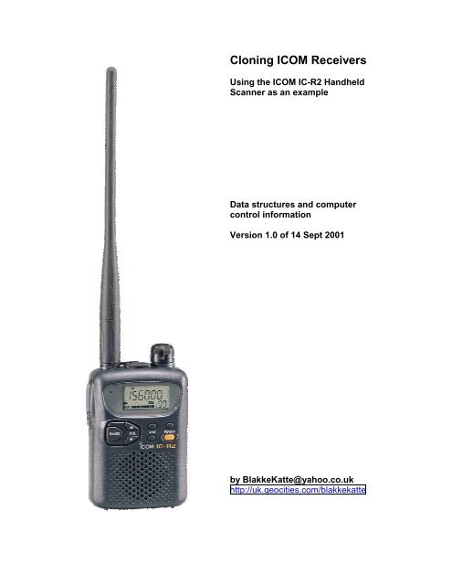
Cloning <strong><strong>IC</strong>OM</strong> Receivers (using <strong>the</strong> <strong><strong>IC</strong>OM</strong> <strong>IC</strong>-<strong>R2</strong> Handheld <strong>Scanner</strong> as anexample.)Table of ContentsAcknowledgements.......................................................................................................... 3<strong>Data</strong> Representations....................................................................................................... 4The ASCII Character Set................................................................................................ 4The ANSI Character Set................................................................................................. 4Hexadecimal Numbers................................................................................................... 4Binary Numbers............................................................................................................ 5ASCII Represented Hexadecimal .................................................................................... 5Background to Cloning an <strong><strong>IC</strong>OM</strong> Radio. ......................................................................... 6Background.................................................................................................................. 6The CI-V System .......................................................................................................... 6Understanding <strong>the</strong> Hardware Interface. ............................................................................ 7Icom OPC-478 Interface. ............................................................................................... 9Icom CT-17 Interface..................................................................................................... 9Differences between <strong>the</strong> OPC-478 and CT-17 Interfaces.................................................. 10O<strong>the</strong>r designs.............................................................................................................. 10Communication Parameters. ......................................................................................... 11Icom Command Language. ............................................................................................ 12Commands Used when Cloning. ................................................................................... 12Transferring <strong>Data</strong>. ....................................................................................................... 14Example line of data.................................................................................................... 15Calculating a Checksum............................................................................................... 16Example Calculation:............................................................................................... 16<strong>IC</strong>-<strong>R2</strong> Memory Structure .............................................................................................. 18Methodology .............................................................................................................. 18Accuracy and Completeness ......................................................................................... 18Overall Structure......................................................................................................... 190000 - 0C7F : Memory Channel <strong>Data</strong>. ........................................................................... 19Frequency Formats .................................................................................................. 21Special Format – Broadcast band with 9kHz separation................................................ 21CTCSS Tones Table ................................................................................................ 220C80-0DFF : Scan Edges. ............................................................................................ 230E10-0E5F : VFO (Band) <strong>Data</strong>. .................................................................................... 230E60-0E6F : Common Parameters................................................................................. 230E70-0E77 : Values on Start-up.................................................................................... 250E80-0E87 : Values on Start-up.................................................................................... 260E88-0E8F : Channel Mode Values............................................................................... 260FA0-0FAF : User Comments ...................................................................................... 260FB0-0FBF : Icom Version Details ............................................................................... 27Appendix A : <strong><strong>IC</strong>OM</strong>'s <strong>IC</strong>F Disk File Format .................................................................. 28Icom’s .<strong>IC</strong>F <strong>for</strong>mat...................................................................................................... 28The First Two Lines. ................................................................................................... 28<strong>IC</strong>F File Coding. ......................................................................................................... 28Appendix B - ASCII Table............................................................................................. 30Appendix C - ANSI Table .............................................................................................. 302
AcknowledgementsI developing this document, I have made extensive use of resources from <strong>the</strong>internet. I wish to acknowledge:•=•=•=•=•=•=•=•=Bruce A Pope <strong>for</strong> his document “Everything you always wanted to knowabout <strong>the</strong> <strong>IC</strong>-R10 that is not in <strong>the</strong> manual.”(http://people.we.mediaone.net/baptpdc/r10/r10.htm). In that document,Bruce describes his decoding of <strong>the</strong> Icom <strong>IC</strong>-R10 scanner.Ekki Plicht (http://www.plicht.de/ekki) who maintains a site with a lot ofIcom programming material. Ekki has also written <strong>the</strong> CIVTest program(http://www.plicht.de/ekki/software/civt.htm) that allows commands to besent to an <strong><strong>IC</strong>OM</strong> radio and displays both <strong>the</strong> commands and <strong>the</strong>responses from <strong>the</strong> radio.Dave (AA6YQ) (http://www.ambersoft.com/Amateur_Radio/index.htm),author of <strong>the</strong> CI-V Explorer program (http://www.qsl.net/civ_commander)and o<strong>the</strong>r Icom computer control resources.Goran Vlaski (http://www.digital-laboratory.de/) <strong>for</strong> his freeware <strong>IC</strong><strong>R2</strong>programming utility and his Icom Clone Utility that can back up and restore<strong>the</strong> <strong>IC</strong>-<strong>R2</strong> by storing clone files on disk.Gommert Buysen (http://www.butel.com.nl) <strong>for</strong> his Advanced RadioControl (ARC) program that can clone <strong>the</strong> <strong>IC</strong>-<strong>R2</strong>, and <strong>the</strong> iclone2 programwhich can back up and restore <strong>the</strong> <strong>IC</strong>-<strong>R2</strong> by storing clone files on disk.Contributors to <strong>the</strong> <strong>IC</strong>-<strong>R2</strong> discussion <strong>for</strong>um athttp://groups.yahoo.com/group/icomr2.Icom <strong>for</strong> <strong>the</strong> DOS based software <strong>for</strong> programming <strong>the</strong> <strong>IC</strong>-<strong>R2</strong>, and <strong>the</strong>ir1991 guide entitled “CI-V : Icom Communications Interface - V ReferenceManual”Raihan Kibria (http://www.tu-darmstadt.de/~rkibria) <strong>for</strong> his frhed (Free HexEditor) program. This easy to use and free utility makes an easy task ofexploring, comparing and changing data files in ei<strong>the</strong>r ASCII or Hex.BlakkeKatteSeptember 20013
<strong>Data</strong> RepresentationsIn this document, data is represented in a variety of ways:•= Characters are represented using <strong>the</strong> ASCII and ANSI character sets.•= Numbers are represented in hexadecimal, ASCII representedhexadecimal, or binary.The ASCII Character SetThe ASCII table describes <strong>the</strong> American Standard Code <strong>for</strong> In<strong>for</strong>mationInterchange, <strong>the</strong> basis of character sets used in most present-day computers.US-ASCII uses only <strong>the</strong> lower seven bits (characters 0 to 127) to convey somecontrol codes, space, numbers, most basic punctuation, and unaccented lettersa-z and A-Z. Appendix B shows <strong>the</strong> ASCII Character set.The ANSI Character SetThe ANSI character set (developed by <strong>the</strong> American National Standards Institute- ANSI), is a standard extension of <strong>the</strong> ASCII character set. The table atAppendix C shows characters 128-255 of <strong>the</strong> ANSI character set.Hexadecimal Numbers.Hexadecimal (Or "hex") numbers count in base 16 (decimal numbers count inbase 10). Hexadecimal numbers are represented using <strong>the</strong> digits 0-9, with <strong>the</strong>irusual meaning, plus <strong>the</strong> letters A-F (or a-f) to represent hexadecimal digits withvalues of (decimal) 10 to 15. The right-most digit counts ones, <strong>the</strong> next countsmultiples of 16, <strong>the</strong>n 16^2 = 256, etc.There are many conventions <strong>for</strong> distinguishing hexadecimal numbers fromdecimal or o<strong>the</strong>r bases in programs. In <strong>the</strong> C programming language <strong>for</strong>example, <strong>the</strong> prefix "0x" is used, e.g. 0x694A11. In Visual Basic <strong>the</strong> prefix "&H"is used, e.g. &H3F6. In this document <strong>the</strong> prefix "$" is used, e.g. $3AF.One of <strong>the</strong> advantages of using hexadecimal numbers is that two charactersrepresent one byte of data (an 8 bit number). For example 159 (decimal) isrepresented as $9F.In this document, numbers are usually represented in a hexadecimal <strong>for</strong>mat:Hexadecimal $0 $1 $2 $3 $4 $5 $6 $7 $8 $9 $A $B $C $D $E $F $10numberDecimalequivalent0 1 2 3 4 5 6 7 8 9 10 11 12 13 14 15 164
Binary NumbersA number representation consisting of zeros and ones used by practically allcomputers because of its ease of implementation using digital electronics andBoolean algebra.A bit is a binary digit. A single one or zero in a binary number.A byte is eight bits. A byte typically holds one character. Two hexadecimalcharacters can represent <strong>the</strong> contents of a byte.A nibble is half a byte. Since a byte is eight bits, a nibble is four bits. Onehexadecimal character can represent <strong>the</strong> contents of one nibble.ASCII Represented HexadecimalA data scheme where two ASCII characters are used to represent one byte ofdata. For example, one data byte containing <strong>the</strong> hexadecimal value $7E (126Decimal, or 1111110 binary) would be represented by <strong>the</strong> two ASCII characters'7E'. The value 3 is represented by <strong>the</strong> two ASCII characters '03'.5
Background to Cloning an <strong><strong>IC</strong>OM</strong> Radio.BackgroundIcom equipment has provision <strong>for</strong> computer control and management.The full implementation can be used <strong>for</strong> two purposes:•= to 'clone' <strong>the</strong> configuration of a radio. That is, to set up <strong>the</strong> operationalparameters of a radio (frequencies, modes, scanning rates etc) ei<strong>the</strong>r bycopying <strong>the</strong>m from ano<strong>the</strong>r radio of <strong>the</strong> same type (cloning) or by usingsoftware to send <strong>the</strong>m to <strong>the</strong> radio. This process is called 'cloning' <strong>the</strong>radio. It generally involves turning <strong>the</strong> radio off after <strong>the</strong> cloning process iscomplete, and turning it back on to reinitialise.•= to control <strong>the</strong> radio while it is operating e.g. to tell <strong>the</strong> radio to change toano<strong>the</strong>r frequency or mode, or to obtain details from <strong>the</strong> radio such asreceived signal strength.The Icom <strong>IC</strong>-<strong>R2</strong> receiver only allows <strong>for</strong> 'cloning' by computer. It does not allow<strong>for</strong> operational control.The CI-V SystemThe current <strong><strong>IC</strong>OM</strong> standard system <strong>for</strong> communication between computer andradio is called <strong>the</strong> <strong><strong>IC</strong>OM</strong> Computer Interface Version 5. This is commonly called<strong>the</strong> CI-V interface standard.The CI-V system allows <strong>for</strong> a computer to communicate, through it's serialcommunications port, to an Icom radio.In its full implementation, <strong>the</strong> CI-V system allows up to four radios to becontrolled from <strong>the</strong> same cable and computer interface. Icom has developed <strong>the</strong>CT-17 interface to allow up to four radios to be connected to one computer.Cloning uses <strong>the</strong> same protocol, but it is assumed that <strong>the</strong>re will only be oneradio communicating with one computer (or two radios communicating with eacho<strong>the</strong>r) and <strong>the</strong> interface hardware can be simpler. Often <strong>the</strong> hardware is installedinside <strong>the</strong> plug <strong>for</strong> connection to <strong>the</strong> computer, with <strong>the</strong> hardware drawing itspower from <strong>the</strong> computer's serial port. Icom has developed <strong>the</strong> OPC-478interface <strong>for</strong> cloning from a computer.6
Understanding <strong>the</strong> Hardware Interface.An interface is needed to convert between <strong>the</strong> low voltage TTL transistor logic of<strong>the</strong> <strong>IC</strong>-<strong>R2</strong> to <strong>the</strong> higher voltage levels of <strong>the</strong> RS-232 computer serialcommunications interface.Hardware required <strong>for</strong> communication between radio and PC is described below.Circuits are provided <strong>for</strong> <strong>the</strong> two <strong><strong>IC</strong>OM</strong> Interface units:•= <strong>the</strong> CT-17 interface used <strong>for</strong> remote control;•= <strong>the</strong> OPC-478 interface used <strong>for</strong> cloningThese devices per<strong>for</strong>m similar functions, but <strong>the</strong> plugs <strong>for</strong> connection to <strong>the</strong> radioare wired differently.The Icom CT-17 interface is based on <strong>the</strong> Maxim Max232 RS-232 LineDriver/Receiver (http://pdfserv.maxim-ic.com/arpdf/1798.pdf). The followingblock diagram of <strong>the</strong> CT-17 interface shows how <strong>the</strong> RS-232 and TTL voltagesare matched toge<strong>the</strong>r, and shows <strong>the</strong> flow of data through <strong>the</strong> device.7
This diagram clearly shows how data transmitted from <strong>the</strong> computer is reflectedback to <strong>the</strong> computer <strong>for</strong> monitoring of <strong>the</strong> transmission. The diagram alsoshows that radio data is also reflected back to <strong>the</strong> radio so that collisions can bedetected.Because <strong>the</strong> transmit-data line and <strong>the</strong> receive-data line are connected toge<strong>the</strong>r,<strong>the</strong> CI-V interface is connected in a wire-OR configuration. When <strong>the</strong> computertransmits a command, <strong>the</strong> command is automatically echoed back as receiveddata, followed by <strong>the</strong> radio's response to <strong>the</strong> command, if any. For example, if aneleven-byte command is transmitted to a device on <strong>the</strong> cable, and a six-byteresponse is sent, <strong>the</strong> computer will receive a total of seventeen bytes (11+6=17).This configuration allows devices on <strong>the</strong> cable to monitor <strong>the</strong>ir own transmissionsin order to detect interface collisions.A collision occurs when two or more devices transmit simultaneously. If acollision occurs, <strong>the</strong> command must be re-transmitted. The radio or computerthat is transmitting reads its own transmissions back from <strong>the</strong> communicationscable. If it detects that ano<strong>the</strong>r device has transmitted at <strong>the</strong> same time (i.e.<strong>the</strong>re has been a collision) <strong>the</strong> radio or computer stops transmitting, listens tomake sure that <strong>the</strong>re are no o<strong>the</strong>r data transmissions on <strong>the</strong> cable, transmits ajamming code (5 characters of value $FC), and retransmits <strong>the</strong> originalcommand.Question: does <strong>the</strong> cloning system actually follow this part of <strong>the</strong> protocol? Thecloning system seems to assume that no more than two devices will be on <strong>the</strong>cable at any one time and <strong>the</strong> protocol seems to minimise <strong>the</strong> possibility ofcollisions occurring during cloning8
Icom OPC-478 Interface.Following is <strong>the</strong> Icom design <strong>for</strong> <strong>the</strong> OPC-478 interface used <strong>for</strong> cloning. Notethat this interface derives its power from <strong>the</strong> RS-232 serial port of <strong>the</strong> connectedcomputer.Source : http://www.lumanet.org/pages/rogerwilco/r_cci.gif.This version adds common part numbers to <strong>the</strong> original <strong><strong>IC</strong>OM</strong> design.Icom CT-17 Interface.Following is <strong>the</strong> Icom design <strong>for</strong> <strong>the</strong> CT-17 interface used <strong>for</strong> computer control ofIcom equipment. This interface allows up to four devices to be controlled by onecomputer.This example is taken from <strong>the</strong> Icom CI-V spec 1986 (source http://www.plicht.de)9
Differences between <strong>the</strong> OPC-478 and CT-17 Interfaces.These two items are electrically similar, except that <strong>the</strong>y terminate in plugs thatare wired differently. The OPC-478 cloning cable generally plugs into <strong>the</strong>earphone socket of <strong>the</strong> radio. The CT-17 serial cable generally plugs into aseparate data socket. The difference in <strong>the</strong> plug wiring is:Plug OPC 478 Cloning Cable CT-17 Serial CableTip unused CI-V dataCentre CI-V data unusedRing Ground GroundA Tip. An OPC-478 cloning cable with a stereo plug can be converted <strong>for</strong> use asa serial cable by using a mono plug to stereo socket converter. This allowsstereo earphones to be used in a mono socket. It effectively connects both <strong>the</strong>tip and <strong>the</strong> centre of <strong>the</strong> plug toge<strong>the</strong>r, so that a signal applied to <strong>the</strong> tip of <strong>the</strong>plug, also appears on <strong>the</strong> centre of <strong>the</strong> stereo plug. If more than one device is tobe connected, external cabling such as common 3.5mm Y-adapters can be usedto connect multiple devices.O<strong>the</strong>r designs.There are a number of sites on <strong>the</strong> internet that provide designs and constructiondetails of RS232 to <strong>IC</strong>-<strong>R2</strong> interfaces. See <strong>for</strong> example <strong>the</strong> collection of links athttp://www.plicht.de/ekki/civ/index.html.An interface similar to <strong>the</strong> CT-17 is published each year in <strong>the</strong> ARRL Handbook(Chapter 22 in <strong>the</strong> 2001 Handbook). The original design was published in 1993in <strong>the</strong> ARRL QST magazine (http://www.arrl.org/tis/info/pdf/9302037.pdf) (copy athttp://groups.yahoo.com/group/Icom_R-10/files/9302037.pdf) but is repeatedeach year in <strong>the</strong> Handbook. The article also gives a good summary of <strong>the</strong> RS-232 protocol and associated communications issues. The printed circuit boardlayout <strong>for</strong> <strong>the</strong> design is at http://www.arrl.org/notes/hbk-templates/iface.pdf.10
Communication Parameters.Following are <strong>the</strong> serial communication parameters <strong>for</strong> <strong>the</strong> Icom CI-V system:ParameterValueStart bits 1<strong>Data</strong> bits 8Stop bits 1ParityNone<strong>Data</strong> rate9600 (configurable). Early equipmenthad <strong>the</strong> baud rate fixed at 2400 baud.HandshakingQ is <strong>the</strong> <strong>IC</strong>-<strong>R2</strong> configurable?None(NB: RTS and CTS are tied toge<strong>the</strong>r at<strong>the</strong> computer end)11
Icom Command Language.Icom uses a simple command language to communicate between computer andradio. The basic <strong>structure</strong> of a command is$FE $FE to-addr fm-addr Cmd SubCmd ---<strong>Data</strong>--- $FD$FE 1 byte <strong>the</strong> preamble (sent twice)to-addr 1 byte <strong>the</strong> address of <strong>the</strong> device to which this command isbeing sentfm-addr 1 byte <strong>the</strong> address of <strong>the</strong> sender of <strong>the</strong> commandCmd 1 byte <strong>the</strong> code <strong>for</strong> <strong>the</strong> command to be followedSubCmd 1 byte Optional. A sub-command <strong>for</strong> some commands<strong>Data</strong> variable <strong>the</strong> data to be processed$FD 1 byte <strong>the</strong> postamble, sent once.In <strong>the</strong> case of <strong>the</strong> <strong>IC</strong>-<strong>R2</strong>, <strong>the</strong> following addresses are used:Computer<strong>IC</strong>-<strong>R2</strong>$EF$EEQuestion: are <strong>the</strong>se generic cloning addresses? If so, <strong>the</strong>re are issues withcloning two radios on <strong>the</strong> same cable. Do <strong>the</strong> <strong>IC</strong>r3 use <strong>the</strong> same address <strong>for</strong>cloning? Does <strong>the</strong> <strong>IC</strong>-R10 have different addresses <strong>for</strong> cloning and control?Also make sure order of addresses is correct, and that examples are consistent.Commands Used when Cloning.The subset of <strong>the</strong> CI-V command set used <strong>for</strong> cloning is:$E0 Interrogate radio <strong>for</strong>version/model/usercomment$FE $FE $EE $EF $E0 $FDFor <strong>the</strong> <strong>IC</strong>-<strong>R2</strong>, <strong>the</strong> Icom provided software will send$21 $27 $00 $00 if it is unsure of <strong>the</strong> model number.The software subsequently uses <strong>the</strong> value returnedfrom <strong>the</strong> radio (see command $E1).For my version of <strong>the</strong> <strong>IC</strong>-<strong>R2</strong> <strong>the</strong> model data is $21$27 $00 $01.(A model code of $00 $00 $00 $00 can be used inthis command. If it is used, any radio will respond12
$E1 Returned data (fromradio)with its actual model number)$FE $FE $EF $EE $E1 $FDThe model data returned from <strong>the</strong> radio should beused in all subsequent commands.The user data returned from <strong>the</strong> radio is <strong>the</strong> usercomment field loaded into memory when cloning(see details under "Memory Structure" later in thisdocument.)$E2 Set Radio into“Clone Out” mode.(Memory Read)O<strong>the</strong>r data in my model returns ($0A $80 $01).Goran Vlaski in his software shows this asrepresenting internal switch settings and <strong>the</strong> state ofmods and fixes)$FE $FE $EE $EF $E2 $FDThe values <strong>for</strong> <strong>the</strong> model data should always bethose returned by <strong>the</strong> radio.The radio responds by returning all of its memorydata - see command $E4 <strong>for</strong> <strong>the</strong> <strong>for</strong>mat.$E3 Set radio into “CloneIn” Mode.(Memory Write)$FE $FE $EE $EF $E3 $FDThe values <strong>for</strong> <strong>the</strong> model data should always bethose returned by <strong>the</strong> radio.The radio displays "clone in" on its LCD.$E4 Payload data.(Can be fromcomputer to radio tobe written tomemory, or fromradio to computer.)This command must be followed by valid memorydata <strong>for</strong> uploading - see command $E4 <strong>for</strong> <strong>the</strong><strong>for</strong>mat.$FE $FE $EE $EF $E4 $FD (fromcomputer to radio)$FE $FE $EF $EE $E4 $FD (fromradio to computer)The line of data contains <strong>the</strong> memory address, <strong>the</strong>payload length, <strong>the</strong> payload data, a checksum.The <strong>for</strong>mat of a line of data transmitted with thiscommand is discussed in detail later in this paper.13
$E5 Termination code.Send to radio at endof cloning memorywrite operation$E6 Termination Result.Sent by radio at endof cloning memorywrite operation$FE $FE $EE $EF $E5 $FDThe data in this command decodes to 'Icom Inc.'This command must be sent or <strong>the</strong> cloningoperation will terminate with an error.$FE $FE $EF $EE $E6 $00 $FDThis is an acknowledgement from <strong>the</strong> radio giving<strong>the</strong> termination status of <strong>the</strong> cloning operation.$00 : Completed with no errors$01 : Completed with errorsIf <strong>the</strong> operation was unsuccessful, <strong>the</strong> radio willdisplay CL Err on its LCD, and will have to bepowered off to recover. On restart it reinitialises in aminimal default configuration.Transferring <strong>Data</strong>.The cloning process transfers data directly to <strong>the</strong> memory of <strong>the</strong> radio. The datatransfer command provides details of <strong>the</strong> memory locations and data to betransferred.The command that transfers data to or from a radio has a simple <strong>structure</strong>. Thedata is transferred using a series of commands, each with <strong>the</strong> same basic layout.Commandsequence toload data from<strong>the</strong> computerinto radiomemory<strong>Data</strong>command preamble$FE $FEcode to communicate $EE $EFfrom PC to radiocommand code <strong>for</strong> $E4data transferStarting Memory AddressNumber of bytes of data to beloaded<strong>Data</strong> to be loaded2 ASCII representedhexadecimal numbers(4 characters)1 ASCII representedhexadecimal number(2 charactersASCII representedhexadecimal numbers.(2 characters pernumber)14
Terminatingcommand byteshowing datatransfer iscomplete.Checksum1 ASCII representedhexadecimal number.(2 characters)One hexadecimal number with <strong>the</strong> value $FD.Representation of <strong>the</strong> data to be transferred<strong>Data</strong> being transferred is encoded in ASCII represented hexadecimal. TwoASCII characters are used to represent one byte of data.Representing a numberDecimal number 249Changed to$F9hexadecimalconverted to characters 'F' '9' F9 would be seen in a word processorRepresenting CharactersCharacter string IcomChanged to$49 $63 $6F $6Dhexadecimal string('I' is <strong>the</strong> 49th letter in<strong>the</strong> ASCII table, 'c' is<strong>the</strong> 63rd, o is <strong>the</strong> 6Fth, m is <strong>the</strong> 6D th)Converted tocharacters4 9 6 3 6 F 6 D as seen in wordprocessorExample line of dataAn Icom command frame transferring data from computer to radio looks like this:Line of dataþþîïä00301012640000000080061266000000008006C6ýThe above line contains this in<strong>for</strong>mation:Command command preamble þþ $FE $FEsequence toload data from<strong>the</strong> computerinto radiomemorycode to communicatefrom PC to radiocommand code <strong>for</strong>data transferîïä$EE $EF$E415
Starting memory address (e.g. 30Hex)Length of data (e.g. 10 Hex or 16decimal)<strong>Data</strong> (32 characters representing16 bytes of data)ChecksumTerminating command byteshowing data is complete.00301012640000000080061266000000008006C6ý$FDCalculating a Checksum.A checksum is used to trap errors in <strong>the</strong> data transmission. The transmittercalculates <strong>the</strong> checksum on <strong>the</strong> data it sends. The receiver recalculates <strong>the</strong>checksum on <strong>the</strong> data it receives. If part of <strong>the</strong> data is corrupted in transmission,<strong>the</strong> checksums will be different, and <strong>the</strong> receiver knows <strong>the</strong>re has been an error.(If an error is detected, <strong>the</strong> radio stops <strong>the</strong> cloning operation and displays ‘CL Err’(or Clone Error) on its LCD. The radio has to be reset to continue.The CI-V system uses a very basic ‘twos-complement’ checksum. It will trapbasic errors, but some more complex errors may not be detected.(Twos complement is a number system used in some computers to representnegative numbers in binary. Each bit of <strong>the</strong> number is inverted (zeros arereplaced with ones and vice versa, and <strong>the</strong>n one (000...0001) is added (ignoringoverflow)Example Calculation:Using logical operations on binary numbers, <strong>the</strong> checksum calculation looks likethis.Address,payload00 30 10 12 64 00 00 00 00 80 06 12 66 00 00 0000 80 06length, anddata dividedinto 2 digi<strong>the</strong>x numbersTotal of all <strong>the</strong> $023A 0000 0010 0011 1010above 2 digi<strong>the</strong>x numbers.Get <strong>the</strong> ones $023A XOR $FFFF = $FDC5 1111 1101 1100 0101complementinverseAdd one toget <strong>the</strong> twoscomplement$FDC5 + 1 = $FDC6 1111 1101 1100 011016
The$FDC6 AND $00FF = $C6 0000 0000 1100 0110checksum istwo byteslong. Weonly need onebyte (eightbits). Maskout <strong>the</strong> highend byteChecksum $C6 1100 011017
<strong>IC</strong>-<strong>R2</strong> Memory StructureMethodologyTo find out <strong>the</strong> memory <strong>structure</strong> of <strong>the</strong> <strong>IC</strong>-<strong>R2</strong>, <strong>the</strong> following methods were used:•= The official <strong><strong>IC</strong>OM</strong> CS-<strong>R2</strong> software was used. A copy was kept of a basic.<strong>IC</strong>F file produced by that software. Using <strong>the</strong> program, one change wasmade to <strong>the</strong> configuration of <strong>the</strong> radio, and <strong>the</strong> changed configuration wassaved in a second .<strong>IC</strong>F file. The two files were compared and changesidentified. This was repeated <strong>for</strong> each function provided by <strong>the</strong> software.•= A similar procedure was followed using software produced by o<strong>the</strong>rs. Inthis case <strong>the</strong> changes were uploaded to <strong>the</strong> radio to confirm that <strong>the</strong>software was in fact producing valid results.•= An analysis of .<strong>IC</strong>F files also identified areas of data which appeared tohave a useful purpose, but which were not being altered by any of <strong>the</strong>software packages. By guessing <strong>the</strong> <strong>for</strong>mat, making changes to <strong>the</strong> data,and uploading <strong>the</strong> altered data into <strong>the</strong> radio, it is sometimes possible tofind <strong>the</strong> purpose of <strong>the</strong> data fields by finding <strong>the</strong> changed behaviour of <strong>the</strong>radio.It can be seen that this is a time consuming, laborious exercise that requires a lotof attention to detail.Accuracy and CompletenessBecause of <strong>the</strong> process used, <strong>the</strong> memory table detailed in this document is notguaranteed to be error free, and anyone relying on <strong>the</strong> data should confirm itsaccuracy.There are also a number of areas in memory that appear to be used by <strong>the</strong> radio,but which have a purpose that has not been identified. The table should not beregarded as complete.18
Overall StructureMemoryLocationsHex Decimal0000-0C7F0C80-0DFF0E00-0E0F0E10-0E5F0E60-0E6F0E70-0E770E78-0E7F0E80-0E870E88-0E8F0E90-0F9F0FA0-0FAF0FB0-0FBFLengthBytes<strong>Data</strong>0-3199 3200 MemoryChannel <strong>Data</strong>3200 -35833584 –35993600 –36793680 –36953696 –37033704 –37113712 –37193720 -37273728 –39994000 –40154016 –4031Comments400 memorychannels, of 8bytes each384 Scan Edges 24 pairs ScanEdges of 16bytes <strong>for</strong> eachpair16 Unused?80 VFO data 10 VFO settings.16 Commonparameters16 Values atstartup8 Unknown?1 CommonParameters8 skip values <strong>for</strong>channel mode272 Unused?16 Comments User comment16 Icom Versiondetails0000 - 0C7F : Memory Channel <strong>Data</strong>.The <strong>IC</strong>-<strong>R2</strong> has 8 memory banks with 50 channels in each bank. This gives atotal of 400 memory channels to be stored by <strong>the</strong> <strong>IC</strong>-<strong>R2</strong>. Details of <strong>the</strong> memorychannels are <strong>the</strong> first thing stored in <strong>the</strong> <strong>R2</strong>. Each memory channel takes up 8bytes of memory <strong>for</strong> storage. Storage is in 4 bit units or ‘nibbles’.The memory does not divide channels into banks - only <strong>the</strong> 400 channels arestored. Only <strong>the</strong> programs used by <strong>the</strong> radio distinguish <strong>the</strong> banks.19
The same <strong>structure</strong> is used <strong>for</strong> each edge of a Scan Edge pair and <strong>for</strong> VFO data.The <strong>structure</strong> is as follows.Bytes Nibbles Total Purpose Values0-2 0-5 24 bits Frequency See separate note onfrequency <strong>for</strong>mat3 6 4 bits Duplex 0 = Simplex1 = Simplex2 = -Duplex3 = +Duplex3-5- 7-11 20 bits Offset See separate notes onfrequency <strong>for</strong>mat6 12 Leftmost 2bits ofnibble 12 (atotal of 2bits)6 12-13 Rightmost2 bits ofnibble 12and all ofnibble 13 (atotal of 6bits)7 14 leftmost 2bits7 14 Rightmost2 bits7 15 Rightmost4 bitsModeCTCSS ToneProgram SkipTone SquelchTuning Step0=FM (i.e. 00xx)1=WFM i.e. (01xx)2=AM (i.e. 10xx)There are 50 CTCSSTones.Range of values is $0 to$31 (0-49 decimal)$0 = xx00 0000$31 = xx11 0001See separate table <strong>for</strong> listof preset tones and <strong>the</strong>irdata values)0=Scan (00xx)1=Program Skip (01xx)2=Scan Skip (10xx)0=off (xx00)1=on (xx01)There are 10 tuning steps0=5 kHz1=6.25 kHz2=10 kHz3=12.5 kHz4=15 kHz5=20 kHz6=25 kHz7=30 kHz8=50 kHz9=100 kHzF=9kHz in AM band ?Auto????20
Frequency FormatsFrequencies and offsets are stored in kilohertz. Resolution and rounding? TheIcom CS<strong>R2</strong> software shows 5 places after <strong>the</strong> decimal point)As an example, 123456 represents 123456 kHz or 123.456 MHz.Frequency <strong>for</strong>mats are in ASCII represented hexadecimal <strong>for</strong>mat where <strong>the</strong>leading two decimal digits will sometimes be represented by one hexadecimalcharacter.Frequencies are stored in 6 nibbles(3 bytes). Offsets are stored in 5 nibbles.For frequecies:•= 1200.000 MHz is stored as C00000•= 200.000 MHz is stored as 200000•= 1,234.567 MHz is stored as C34567For Offsets:•= 200.000 MHz is stored as C0000•= 20.000 MHz is stored as 20000•= 123456 MHz is stored as C3456.Special Format – Broadcast band with 9kHz separation.Some models accommodate <strong>the</strong> fact that, in some countries, stations in <strong>the</strong>broadcast band have a separation of 9kHz. O<strong>the</strong>r countries provide <strong>for</strong>broadcast band separation of 10 kHz. The ability to handle 9 kHz separation isprogrammed into <strong>the</strong> <strong>IC</strong>-<strong>R2</strong> in an unusual way.The frequencies in <strong>the</strong> broadcast band range of 0.495 MHz to 1.620 MHz have adifferent <strong>for</strong>mat:Frequency Format Calculation0.495 00FFFF 0.495+0*0.0090.504 01FFFF 0.495+1*0.0090.513 02FFFF 0.495+2*0.009…. …. ….0.576 09FFFF 0.495+9*0.0090.585. 0AFFFF 0.495+10*0.0090.594 0BFFFF 0.495+11*0.009…. …. ….1.602 7BFFFF 0.495+123*0.00921
1.611 7CFFFF 0.495+124*0.0091.620 7DFFFF 0.495+125*0.009This frequency <strong>for</strong>mat occupies 6 digits. The mode must be fixed as AM.Duplex, Offset, Tone Squelch, CTCSS Tone are not available. Only ScanSkip can be programmed.Following is an example (spaces added <strong>for</strong> clarity).13FFFF000000880F 27FFFF000000880FThis shows two stations 0.666 (13 hex [i.e. 19 decimal] * 0.009 + 0.495) and0.846 (27 hex [i.e. 39 decimal] * 0.009 + 0.495). It shows Duplex set to 0,Offset frequency set to 0, An arbitrary CTCSS tone (no 8), tuning step set toF, mode set to AM, and <strong>the</strong> scan option set to ‘scan’.CTCSS Tones Table<strong>Data</strong> Value CTCSS Tone <strong>Data</strong> Value CTCSS Tone0 67.0 25 156.71 69.3 26 159.82 71.9 27 162.23 74.4 28 165.54 77.0 29 167.95 79.7 30 171.36 82.5 31 173.87 85.4 32 177.38 88.5 33 179.99 91.5 34 183.510 94.8 35 186.211 97.4 36 189.912 100.0 37 192.813 103.5 38 196.614 107.2 39 199.515 110.9 40 203.516 114.8 41 206.517 118.8 42 210.718 123.0 43 218.119 127.3 44 225.720 131.8 45 229.121 136.5 46 233.622 141.3 47 241.823 146.2 48 250.324 151.4 49 254.122
0C80-0DFF : Scan Edges.There are 24 pairs of scan edges. Each pair has an upper frequency limit or edge(with all details), and a lower frequency limit (or edge). Each edge has <strong>the</strong> same<strong>structure</strong> as a memory frequency channel.0E10-0E5F : VFO (Band) <strong>Data</strong>.Each VFO element has <strong>the</strong> same <strong>structure</strong> as a memory frequency channel.VFO(in CS<strong>R2</strong>software)VFO(in <strong>IC</strong>-<strong>R2</strong>manual)VFOGoran'sprogramFrequencyRange of VFO1 0.495 1.6 0.495 - 1.620MHz5 5 5 1.625 - 29.995MHz50 51 51 30 - 107.995 MHz76Air 118 118 108 - 135.995MHzVHF 145 145 136 - 255.095MHz300 370 370 255.1 - 382.095MHzUHF 430 430 382.1 - 769.795MHz800 850 850 769.8 - 960.095MHz1200 1295 1295 960.1 - 1309.995MHzDefaultFrequency onRadioInitialisationNOTE: To be resolved. The documentation gives 9 VFO slots. The data file has10 slots <strong>for</strong> VFO data. Goran Vlaski's program shows 10 VFO slots.0E60-0E6F : Common ParametersByte Total Bytes Purpose Values$0E60 1 Dial Select 0=100 kHz1=1 MHz2=10 MHz$0E61 1 Priority 0=off1=on2=bell23
Question: where are <strong>the</strong>details of <strong>the</strong> priorityfrequency held?$0E62 1 Scan Resume 0 = 0 sec1=1 sec…..5=5 sec6=Hold$0E63 1 Scan Pause 0=2 sec1=4 sec…9=20 secA=hold$0E64 1 Program skip 0=off1=on$0E65 1 Bank scan 0=bank1=all$0E66 1 Expand Mode 0=off1=on$0E67 1 Channel mode This also sets values at OE80 byte 20=off1=on(in both locations)$0E68 1 Operation 0=offBeep$0E69 1 Displaybacklight1= on0=off1=on2=auto$0E6A 1 Auto Power Off 0=off1=30 min2=60 min3=90 min4=120 min$0E6B 1 Power Save 0=off1=auto$0E6C 1 Monitor Mode 0=Push1=Hold$0E6D 1 Dial Speed 0=off1=on$0E6E 1 Scan Edge 0=P01=P1…..18=P2419=Band1A=All24
$0E6F 1 Lock Mode 0=Normal1=No SQL2=No Vol3=All0E70-0E77 : Values on Start-upByte Total Bytes Purpose Values$0E70 current menuoption (TheMenu optionwhich willappear whenmenu is nextcalled up)0=skip1=Dsel2=TSQL3=Tone4=Dup5=Offset6=Resume7=Pause8=prio9=BeepA=LightB=AP offC=PsaveD=MoniE=SpeedF=Lock10=CH$0E71 VFO to use(This relates to<strong>the</strong> ‘band’ touse’)$0E72 Channelnumber11=ExpandBottom edge of <strong>the</strong> ‘band’0=0.495 MHz1=1.620MHz2=53=514=1185=1456=3707=4308=8509=1295.0 MHzA=use Channel Mode1=1……3D = 62$0E73 Squelch Level 1=Auto2=Level 125
$0E74 MemoryChannel$0E75$0E76$0E77……A=Level 9some error here 16=22,18=24, 18=399(18F)0E80-0E87 : Values on Start-upByte Total Bytes Purpose Values$0E80 top attenuator 2=off, 6=on (0=off, 4=on)bottomOperation onPower Up$0E81 top Memory orVFObottom$0E82$0E83$0E84$0E85$0E86$0E87What is correct figure here?Normal=0Scan Tone=1Normal Scan=28=mem, 0=VFO (set to 0 if inchannel modeCh Mode 0=off, 1=on0E88-0E8F : Channel Mode ValuesByte Total Bits Purpose Values$0E98-$0E8F64 TV ChannelSkip1 Bit per channel0=off, 1=onIs this correct????????Goran's program showsonly 62 channels0FA0-0FAF : User CommentsThese locations contain 16 characters of user comments in text. For example:55 73 65 72 20 43 6F 6D 6D 65 6E 74 20 31 32 33U s e r C o m m e n t 1 2 326
0FB0-0FBF : Icom Version DetailsThese memory locations contain <strong>the</strong> following fixed data that is not amended.49 63 6F 6D 43 6C 6F 6E 65 46 6F 72 6D 61 74 33I c o m C l o n e F o r m a t 3--00--27
Appendix A : <strong><strong>IC</strong>OM</strong>'s <strong>IC</strong>F Disk File FormatIcom’s .<strong>IC</strong>F <strong>for</strong>matIcom provides a DOS software program (CS<strong>R2</strong>) to load data into, and downloaddata from <strong>the</strong> <strong>IC</strong>-<strong>R2</strong>. This program stores data files in a .<strong>IC</strong>F Format. This<strong>for</strong>mat is based on <strong>the</strong> <strong>for</strong>mat sent to <strong>the</strong> <strong>IC</strong>-<strong>R2</strong>, with some differences:•=•=•=•=•=•=The file is a text file. That is, it contains lines of ASCII characters, wi<strong>the</strong>ach line being terminated with a Carriage Return and Line Feedcombination.There are two extra lines at <strong>the</strong> beginning. The first contains some datawhich identifies <strong>the</strong> equipment model, and is used in <strong>the</strong> set up of <strong>the</strong> datatransfer process. The second line contains user comments that are readby <strong>the</strong> Icom CS<strong>R2</strong> program.The leading command bytes are not includedThe checksum is not includedThe terminating command byte is not includedThe data is encoded into a character based <strong>for</strong>mat. This encoding has tobe removed be<strong>for</strong>e <strong>the</strong> data can be usedThe First Two Lines.The first line in <strong>the</strong> file contains <strong>the</strong> model number returned by <strong>the</strong> radio. Forexample:First Line of <strong>IC</strong>F File 21270001The second line contains a # sign followed by <strong>the</strong> user comments contained in<strong>the</strong> radio. The <strong><strong>IC</strong>OM</strong> programs use this to provide a description when opening<strong>the</strong> file. An example second line is:Second Line of <strong>IC</strong>F File #User CommentBoth <strong>the</strong>se lines are in normal, unencoded, text.<strong>IC</strong>F File Coding.The remainder of <strong>the</strong> <strong>IC</strong>F file contains <strong>the</strong> memory data that would be sent to (orreceived from) <strong>the</strong> radio. Only <strong>the</strong> starting memory location, length of data, and<strong>the</strong> data itself is recorded. The checksum is not recorded in an <strong>IC</strong>F file. Thedata in an <strong>IC</strong>F File is encoded using a simple coding system. Lines in an .<strong>IC</strong>F filelook like this:Encoded .<strong>IC</strong>F dataHex data after encodingremoved (and with <strong>the</strong>Carriage Return and LineFeed removed)ggjghghimkggggggggoggmhimmggggggggoggm0030101264000000008006126600000000800628
Removing <strong>the</strong> encoding is simple, as <strong>the</strong> following example shows.The letter ‘g’ is <strong>the</strong> 103 rd character in <strong>the</strong> ASCII character set. Deducting 55 fromthat leaves 48. The 48 th character in <strong>the</strong> ASCII character set is <strong>the</strong> number ‘0’.Thus, ‘g’ represents ‘0’. ‘h’ represents ‘1’ and so on.code lettergposition in ASCII table 103subtract 55 103 - 55 = 48Character at 48th position in ASCII '0'tablecode letter }position in ASCII table 125subtract 55 125 - 55 = 70Character at 70th position in ASCII 'F'tableAs hexadecimal digits represent <strong>the</strong> data transferred to <strong>the</strong> <strong>IC</strong>-<strong>R2</strong>, only <strong>the</strong> 16hexadecimal digits need to be decoded. The following table lists <strong>the</strong> code lettersfrom <strong>the</strong> file, and <strong>the</strong> hexadecimal digits <strong>the</strong>y represent.code hexdigitcode hexdigitg 0 o 8h 1 p 9i 2 x Aj 3 y Bk 4 z Cl 5 { Dm 6 | En 7 } F--00--29
Appendix B - ASCII TableChar Dec Hex Char Dec Hex Char Dec Hex Char Dec Hex(nul) 0 0x00 (sp) 32 0x20 @ 64 0x40 ` 96 0x60(soh) 1 0x01 ! 33 0x21 A 65 0x41 a 97 0x61(stx) 2 0x02 " 34 0x22 B 66 0x42 b 98 0x62(etx) 3 0x03 # 35 0x23 C 67 0x43 c 99 0x63(eot) 4 0x04 $ 36 0x24 D 68 0x44 d 100 0x64(enq) 5 0x05 % 37 0x25 E 69 0x45 e 101 0x65(ack) 6 0x06 & 38 0x26 F 70 0x46 f 102 0x66(bel) 7 0x07 ' 39 0x27 G 71 0x47 g 103 0x67(bs) 8 0x08 ( 40 0x28 H 72 0x48 h 104 0x68(ht) 9 0x09 ) 41 0x29 I 73 0x49 i 105 0x69(nl) 10 0x0a * 42 0x2a J 74 0x4a j 106 0x6a(vt) 11 0x0b + 43 0x2b K 75 0x4b k 107 0x6b(np) 12 0x0c , 44 0x2c L 76 0x4c l 108 0x6c(cr) 13 0x0d - 45 0x2d M 77 0x4d m 109 0x6d(so) 14 0x0e . 46 0x2e N 78 0x4e n 110 0x6e(si) 15 0x0f / 47 0x2f O 79 0x4f o 111 0x6f(dle) 16 0x10 0 48 0x30 P 80 0x50 p 112 0x70(dc1) 17 0x11 1 49 0x31 Q 81 0x51 q 113 0x71(dc2) 18 0x12 2 50 0x32 R 82 0x52 r 114 0x72(dc3) 19 0x13 3 51 0x33 S 83 0x53 s 115 0x73(dc4) 20 0x14 4 52 0x34 T 84 0x54 t 116 0x74(nak) 21 0x15 5 53 0x35 U 85 0x55 u 117 0x75(syn) 22 0x16 6 54 0x36 V 86 0x56 v 118 0x76(etb) 23 0x17 7 55 0x37 W 87 0x57 w 119 0x77(can) 24 0x18 8 56 0x38 X 88 0x58 x 120 0x78(em) 25 0x19 9 57 0x39 Y 89 0x59 y 121 0x79(sub) 26 0x1a : 58 0x3a Z 90 0x5a z 122 0x7a(esc) 27 0x1b ; 59 0x3b [ 91 0x5b { 123 0x7b(fs) 28 0x1c < 60 0x3c \ 92 0x5c | 124 0x7c(gs) 29 0x1d = 61 0x3d ] 93 0x5d } 125 0x7d(rs) 30 0x1e > 62 0x3e ^ 94 0x5e ~ 126 0x7e(us) 31 0x1f ? 63 0x3f _ 95 0x5f (del) 127 0x7fAppendix C - ANSI TableChar Dec Hex Char Dec Hex Char Dec Hex Char Dec Hex€ 128 80 Ÿ 160 A0 À 192 CO à 224 E0 129 81 161 A1 Á 193 C1 á 225 E1‚ 130 82 ¡ 162 A2 Â 194 C2 â 226 E2ƒ 131 83 ¢ 163 A3 Ã 195 C3 ã 227 E3„ 132 84 £ 164 A4 Ä 196 C4 ä 228 E4… 133 85 ¤ 165 A5 Å 197 C5 å 229 E5† 134 86 ¥ 166 A6 Æ 198 C6 æ 230 E6‡ 135 87 ¦ 167 A7 Ç 199 C7 ç 231 E7ˆ 136 88 § 168 A8 È 200 C8 è 232 E8‰ 137 89 ¨ 169 A9 É 201 C9 é 233 E9Š 138 8A © 170 AA Ê 202 CA ê 234 EA30
‹ 139 8B ª 171 AB Ë 203 CB ë 235 EBŒ 140 8C « 172 AC Ì 204 CC ì 236 EC 141 8D ¬ 173 AD Í 205 CD í 237 EDŽ 142 8E 174 AE Î 206 CE î 238 EE 143 8F ® 175 AF Ï 207 CF ï 239 EF 144 90 ¯ 176 BO Ð 208 D0 ð 240 F0‘ 145 91 ° 177 B1 Ñ 209 D1 ñ 241 F1’ 146 92 ± 178 B2 Ò 210 D2 ò 242 F2“ 147 93 ² 179 B3 Ó 211 D3 ó 243 F3” 148 94 ³ 180 B4 Ô 212 D4 ô 244 F4• 149 95 ´ 181 B5 Õ 213 D5 õ 245 F5– 150 96 µ 182 B6 Ö 214 D6 ö 246 F6— 151 97 183 B7 × 215 D7 ÷ 247 F7˜ 152 98 · 184 B8 Ø 216 D8 ø 248 F8 153 99 ¸ 185 B9 Ù 217 D9 ù 249 F9š 154 9A ¹ 186 BA Ú 218 DA ú 250 FA› 155 9B º 187 BB Û 219 DB û 251 FBœ 156 9C » 188 BC Ü 220 DC ü 252 FC 157 9D ¼ 189 BD Ý 221 DD ý 253 FDž 158 9E ½ 190 BE Þ 222 DE þ 254 FEŸ 159 9F ¾ 191 BF ß 223 DF ÿ 255 FF31


