ARINC Protocol Tutorial - Ecrin Systems
ARINC Protocol Tutorial - Ecrin Systems
ARINC Protocol Tutorial - Ecrin Systems
- No tags were found...

Create successful ePaper yourself
Turn your PDF publications into a flip-book with our unique Google optimized e-Paper software.
CopyrightsCopyright © 2000-2004 Condor Engineering, Inc.All rights reserved.This document may not, in whole or part, be; copied; photocopied; reproduced; translated;reduced or transferred to any electronic medium or machine-readable form without priorconsent in writing from Condor Engineering, Inc.<strong>ARINC</strong> <strong>Protocol</strong> <strong>Tutorial</strong> (1500-029)Document Date: 16 July, 2004Document Revision: 1.07Condor Engineering, Inc.101 W. Anapamu StreetSanta Barbara, CA 93101(805) 965-8000(805) 963-9630 (fax)support@condoreng.com (email)http://www.condoreng.com
Contents and TablesContentsChapter 1Chapter 2<strong>ARINC</strong> 429 <strong>Tutorial</strong>Introduction....................................................................................................1About <strong>ARINC</strong>................................................................................................2What is <strong>ARINC</strong> 429? ...............................................................................2<strong>ARINC</strong> 429 Usage ...................................................................................3<strong>ARINC</strong> 429 Electrical Characteristics ..........................................................3<strong>Protocol</strong> ....................................................................................................5Bit Timing and Slew Rate........................................................................6<strong>ARINC</strong> 429 Word Format.............................................................................7Parity.........................................................................................................7SSM..........................................................................................................7Data...........................................................................................................8SDI............................................................................................................8Label.........................................................................................................8Transmission Order..................................................................................8<strong>ARINC</strong> 429 Data Types ................................................................................9BCD Data Encoding.................................................................................9BNR Data Encoding.................................................................................9Mixed Formats .......................................................................................10Discrete Data Formats............................................................................11Maintenance Data...................................................................................12Data Translation Method.............................................................................12Bit Oriented <strong>Protocol</strong>s .................................................................................15Other <strong>ARINC</strong> <strong>Protocol</strong>s<strong>ARINC</strong> 419..................................................................................................19<strong>ARINC</strong> 453..................................................................................................20<strong>ARINC</strong> 561/568...........................................................................................20<strong>ARINC</strong> 573..................................................................................................20<strong>ARINC</strong> 575..................................................................................................21<strong>ARINC</strong> 582..................................................................................................21<strong>ARINC</strong> <strong>Protocol</strong> <strong>Tutorial</strong>i
<strong>ARINC</strong> 615..................................................................................................21<strong>ARINC</strong> 629..................................................................................................22<strong>ARINC</strong> 708..................................................................................................22<strong>ARINC</strong> 717..................................................................................................22Appendix ATable of FiguresList of TablesReferencesList of References........................................................................................23Figure 1. <strong>ARINC</strong> 429 Bit Encoding Example ..............................................5Figure 2. Slew Rates and Bit Timing Diagram.............................................6Figure 3. Generalized <strong>ARINC</strong> Word Format................................................7Figure 4. Generalized BCD Word Format....................................................9Figure 5. BCD Word Format Example .........................................................9Figure 6. Generalized BNR Word Format..................................................10Figure 7. Example BNR Encoding..............................................................10Figure 8. File Transfer Scheme Version 1 (no Windows)..........................16Figure 9. <strong>ARINC</strong> 561 6-Wire Bit Encoding ...............................................20Figure 10. Harvard Bi-phase Bit Encoding.................................................21Table 1. Partial List of Equipment IDs .........................................................4Table 2. <strong>ARINC</strong> 429 Characteristic Summary .............................................5Table 3. <strong>ARINC</strong> Bit Characteristics..............................................................6Table 4. SSM Codes for BCD data ...............................................................7Table 5. SSM Codes for BNR data ...............................................................7Table 6. Dedicated Discrete Example.........................................................11Table 7. Examples of BCD Labels..............................................................13Table 8. Examples of BNR Labels..............................................................13Table 9. Equipment IDs for Tables 6 and 7 ................................................13Table 10. Message Sequence for Label 241 ...............................................14Table 11. <strong>Systems</strong> Using Bit Oriented Communicationsand Their Address Labels............................................................................17ii<strong>ARINC</strong> <strong>Protocol</strong> <strong>Tutorial</strong>
CHAPTER 1<strong>ARINC</strong> 429 <strong>Tutorial</strong>IntroductionThis document provides an overview of <strong>ARINC</strong> 429 and other <strong>ARINC</strong>protocols. <strong>ARINC</strong> 429 is the most commonly used data bus forcommercial and transport aircraft. This document explains the origins ofthe <strong>ARINC</strong> Corporation, the data bus specification and where <strong>ARINC</strong> 429is used. Then it summarizes the principal electrical and datacharacteristics, which are defined in the specification.This document is not a complete description of <strong>ARINC</strong> 429. It is intendedonly as a brief tutorial and isn’t meant to replace the completespecification, which can be purchased from <strong>ARINC</strong> (see Appendix A,“References” for contact information).<strong>ARINC</strong> 429 employs unidirectional transmission of 32 bit words over twowire twisted pairs using bipolar RZ format. This tutorial includes chartsillustrating slew times and bit timing. It describes the five fields in eachword and explains the use of labels. Messages are repeated at specifiedintervals with typical applications sending groups or frames of messages.Examples are given of the commonly used word formats such as BNR,BCD, Discrete data, and other formats. Also explained is a newer bitorientedprotocol, sometimes called the Williamsburg <strong>Protocol</strong>, which hasbeen introduced to provide an improved method of transmitting files ofdata. Additionally, the document includes a brief explanation of other<strong>ARINC</strong> specifications, such as 419, 561, 573, 582, 615, and 717.Frequent references are made to <strong>ARINC</strong> Specification 429 and manyexamples are taken from it. This tutorial is intended to introduce you to thesubject. Individuals needing more detail should obtain a copy of thespecification from <strong>ARINC</strong> and also should consider consulting othersources identified in the list of references.This document has been prepared by Condor Engineering Incorporated foruse by its employees and customers. Condor is a full-service manufacturerof Test, Simulation, and Interface products for avionics data buses. Thehardware and software can be used to monitor or simulate data bus<strong>ARINC</strong> <strong>Protocol</strong> <strong>Tutorial</strong> 1
About <strong>ARINC</strong><strong>ARINC</strong> 429 <strong>Tutorial</strong>messages for analyses and for simulating bus operation. To learn about thefull line of Condor products, visit our Web site or contact us by phone orfax. Information can also be obtained via e-mail. See the Copyrights pageof this manual for the latest contact information. Detailed installation anduser manuals are provided with each product, and demonstration softwareis available free of charge.About <strong>ARINC</strong>Aeronautical Radio, Incorporated (<strong>ARINC</strong>) is a major company thatdevelops and operates systems and services to ensure the efficiency,operation, and performance of the aviation and travel industries. It wasorganized in 1929 by four major airlines to provide a single licensee andcoordinator of radio communications outside the government. Onlyairlines and aviation-related companies can be shareholders, although allairlines and aircraft can use <strong>ARINC</strong>’s services. It is now a $280 millioncompany with headquarters in Annapolis, Maryland and over 50 operatinglocations worldwide. The company has two major thrusts:• Communications and information processing services for the aviationand travel industry.• System engineering, development and integration for government andindustry.<strong>ARINC</strong> has provided leadership in developing specifications and standardsfor avionics equipment, and one of these specifications is the focus of thistutorial. Industry-wide committees prepare the specifications andstandards. <strong>ARINC</strong> Specification 429 was developed and is maintained bythe Airlines Electronic Engineering Committee (AEEC) comprisingmembers that represent airlines, government, and <strong>ARINC</strong>.The General Aviation Manufacturers Association (GAMA) in Washington,D.C. also maintains a specification document with <strong>ARINC</strong> 429 labels:“<strong>ARINC</strong> 429 General Aviation Subset”.What is <strong>ARINC</strong> 429?<strong>ARINC</strong> 429 is a specification, which defines how avionics equipment andsystems should communicate with each other. They are interconnected bywires in twisted pairs. The specification defines the electrical and datacharacteristics and protocols, which are used. <strong>ARINC</strong> 429 employs aunidirectional data bus standard known as Mark 33 Digital InformationTransfer System (DITS). Messages are transmitted at a bit rate of either12.5 or 100 kilobits per second to other system elements, which aremonitoring the bus messages. Transmission and reception is on separateports so that many wires may be needed on aircraft, which use a largenumber of avionics systems.2 <strong>ARINC</strong> <strong>Protocol</strong> <strong>Tutorial</strong>
<strong>ARINC</strong> 429 <strong>Tutorial</strong><strong>ARINC</strong> 429 Electrical Characteristics<strong>ARINC</strong> 429 Usage<strong>ARINC</strong> 429 has been installed on most commercial transport aircraftincluding; Airbus A310/A320 and A330/A340; Bell Helicopters; Boeing727, 737, 747, 757, and 767; and McDonnell Douglas MD-11. Boeing isinstalling a newer system specified as <strong>ARINC</strong> 629 on the 777, and someaircraft are using alternate systems in an attempt to reduce the weight ofwire needed and to exchange data at a higher rate than is possible with<strong>ARINC</strong> 429. The unidirectional <strong>ARINC</strong> 429 system provides highreliability at the cost of wire weight and limited data rates. Military aircraftgenerally use a high-speed, bi-directional protocol specified in MilitarySpecifications MIL-STD-1553.Each aircraft may be equipped with different electronic equipment andsystems needing interconnection. A large amount of equipment may beinvolved depending on the aircraft. These are identified in thespecification and are assigned digital identification numbers calledEquipment ID. A partial list of equipment identified in <strong>ARINC</strong>Specification 429-15 can be found in Table 1 along with their digitaladdresses.The specification also identifies a number of systems, which are capable ofinterchanging files of data in a bit-oriented format. Such files may requirethe transmission of a number of messages in sequence. <strong>Systems</strong> capable ofbit-oriented communications and their addresses are listed in Table 10.The SAL is used to identify the recipient of a bit oriented message.<strong>ARINC</strong> 429 Electrical CharacteristicsAn <strong>ARINC</strong> 429 data bus uses two signal wires to transmit 32 bit words.Transmission of sequential words is separated by at least 4 bit times ofNULL (zero voltage). This eliminates the need for a separate clock signalwire. That’s why this signal is known as a self-clocking signal.The nominal transmission voltage is 10 ±1 volts between wires(differential), with either a positive or negative polarity. Therefore, eachsignal leg ranges between +5V and -5V. If one leg is +5V, the other is -5Vand vice versa. One wire is called the “A” (or “+” or “HI”) side and theother is the “B” (or “-” or “LO”) side. This is known as bipolar return-tozero(BPRZ) modulation. The composite signal state may be one of threelevels:• HI which should measure between 7.25 and 11 volts between the twowires (A to B).• NULL which should be between 0.5 and -0.5 (A to B).• LO which should be between -7.25 and -11 volts (A to B).<strong>ARINC</strong> <strong>Protocol</strong> <strong>Tutorial</strong> 3
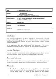
<strong>ARINC</strong> 429 Electrical Characteristics<strong>ARINC</strong> 429 <strong>Tutorial</strong>The received voltage depends on line length and the number of receiversconnected to the bus. No more than 20 receivers should be connected to asingle bus. Since each bus is unidirectional, a system needs to have its owntransmit bus if it is required to respond or to send messages.Table 1. Partial List of Equipment IDsEq. ID Equipment Type Eq. ID Equipment Type001 Flight Control Computer (701) 029 ADDCS (729) and EICAS002 Flight Management Computer (702) 02A Thrust Management Computer003 Thrust Control Computer (703) 02B Perf. Nav. Computer System (Boeing 737)004 Inertial Reference System (704) 02C Digital Fuel Gauging System (A310)005 Attitude and Heading Ref. System (705) 02D EPR Indicator (Boeing 757)006 Air Data system (706) 02E Land Rollout CU/Landing C & LU007 Radio Altimeter (707) 02F Full Authority EEC-A008 Airborne Weather Radar (708) 030 Airborne Separation Assurance System009 Airborne DME (709) 031 Chronometer (731)00A FAC (A310) 032 Passenger Entertain. Tape Reproducer(732)00B Global Positioning System 033 Propulsion Multiplexer (PMUX) (733)00D AIDS Data Management System 034 Fault Isolation and Detection System (734)010 Airborne ILS Receiver (710) 035 TCAS (735)011 Airborne VOR Receiver (711) 036 Radio Management System (736)012 Airborne ADF System (712) 037 Weight and Balance System (737)016 Airborne VHF COM Receiver (716) 038 ADIRS (738)017 DEFDARS-AIDS (717) 039 MCDU (739)018 ATC Transponder (718) 03A Propulsion Discrete Interface Unit019 Airborne HF/SSB System (719) 03B Autopilot Buffer Unit01A Electronic Supervisory Control 03C Tire Pressure Monitoring System01B Digital Flap/Slat Computer (A310) 03D Airborne Vibration Monitor (737/757/767)01C Engine Parameter Digitizer (Engine) 03E Center of Gravity Control Computer01D A/P & F/D Mode Control Panel -757/767 03F Full Authority EEC-B01E Performance Data Computer (Boeing) 040 Cockpit Printer01F Fuel Quantity Totalizer 041 Satellite Data Unit020 DFS System (720) 046 CTU023 Ground Proximity Warning Sys (723) 047 Digital Flight Data Recorder024 ACARS (724) ---- additional items025 Electronic Flt. Instruments (725) ---- “026 Flight Warning Computer (726) ---- “027 Microwave Landing System (727) 241 High Power AmplifierThe transmitting and receiving circuits must be designed for reliablysending and detecting the null transition between high and low states. Theparameters vary with the type of operation as defined in Reference 2. The4 <strong>ARINC</strong> <strong>Protocol</strong> <strong>Tutorial</strong>
<strong>ARINC</strong> 429 <strong>Tutorial</strong><strong>ARINC</strong> 429 Electrical Characteristicsslew rates and tolerances are shown in Figure 1 for both 100K and 12.5Kdata rates.Figure 1. <strong>ARINC</strong> 429 Bit Encoding ExampleTable 2 summarizes <strong>ARINC</strong> 429 characteristics.Table 2. <strong>ARINC</strong> 429 Characteristic SummaryElectrical CharacteristicValueVoltage Levels, each leg with respect to ground +5V, 0V, -5VVoltage Levels, Leg A with respect to Leg B +10V, 0V, -10VBit EncodingBipolar Return to ZeroWord size32 bitsBit Rates100K or 12.5K bits per secondHigh Speed Slew Rate1.5 +/- 0.5 µsecLow Speed Slew Rate10 +/- 5 µsec<strong>Protocol</strong><strong>ARINC</strong> 429 is a very simple, point-to-point protocol. There can be onlyone transmitter on a wire pair. The transmitter is always transmitting either32-bit data words or the NULL state. There is at least one receiver on awire pair; there may be up to 20.In most cases, an <strong>ARINC</strong> message consists of a single data word. Thelabel field of the word defines the type of data that is contained in the restof the word.<strong>ARINC</strong> <strong>Protocol</strong> <strong>Tutorial</strong> 5
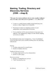
<strong>ARINC</strong> 429 Electrical Characteristics<strong>ARINC</strong> 429 <strong>Tutorial</strong>Bit Timing and Slew RateThe slew rate refers to the rise and fall time of the <strong>ARINC</strong> waveform.Specifically, it refers to the amount of time it takes the <strong>ARINC</strong> signal torise from the 10% to the 90% voltage amplitude points on the leading andtrailing edges of the pulse. See Figure 2.Table 3. <strong>ARINC</strong> Bit CharacteristicsParameter High Speed Low SpeedBit Rate 100K bits/second 12.5K-14.5K bits/secondTime Y (one bit) 10 µsec ± 2.5% 1÷(bit rate) µsec ± 2.5%Time X 5 µsec ± 5% Y/2 µsec ± 5%Pulse Rise Time 1.5 ± 0.5 µsec 10 ± 5 µsecPulse Fall Time 1.5 ± 0.5 µsec 10 ± 5 µsecFigure 2. Slew Rates and Bit Timing Diagram6 <strong>ARINC</strong> <strong>Protocol</strong> <strong>Tutorial</strong>
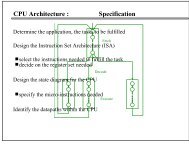
<strong>ARINC</strong> 429 <strong>Tutorial</strong><strong>ARINC</strong> 429 Word Format<strong>ARINC</strong> 429 Word Format<strong>ARINC</strong> data words are always 32 bits and typically use the format shownin Figure 3 which includes five primary fields, namely Parity, SSM, Data,SDI, and Label. <strong>ARINC</strong> convention numbers the bits from 1 (LSB) to 32(MSB).32 31 30 29 11 10 9 8 1P SSM DATA PAD DISCRETESMSBLSBSDILABELFigure 3. Generalized <strong>ARINC</strong> Word FormatParityThe MSB is always the parity bit for <strong>ARINC</strong> 429. Parity is normally set toodd except for certain tests. Odd parity means that there must be an oddnumber of “1” bits in the 32-bit word that is insured by either setting orclearing the parity bit. For example if bits 1-31 contain an even number of“1” bits, bit 32 must be set to create ODD parity. On the other hand, if bits1-31 contain an odd number of “1” bits, the parity bit must be clear.SSMBits 31 and 30 contain the Sign/Status Matrix or SSM. This field containshardware equipment condition, operational mode, or validity of datacontent. Applicable codes are shown in Table 4andTable 5.Table 4. SSM Codes for BCD dataBitMeaning31 300 0 Plus, North, East, Right, To, Above0 1 No Computed Data1 0 Functional Test1 1 Minus, South, West, Left, From, BelowTable 5. SSM Codes for BNR dataBit31 30Meaning<strong>ARINC</strong> <strong>Protocol</strong> <strong>Tutorial</strong> 7
<strong>ARINC</strong> 429 Word Format<strong>ARINC</strong> 429 <strong>Tutorial</strong>0 0 Failure Warning0 1 No Computed Data1 0 Functional Test1 1 Normal OperationDataBits 29 through 11 contain the data, which may be in a number of differentformats. Some examples are provided later in the tutorial. There are alsomany non-standard formats that have been implemented by variousmanufacturers. In some cases, the data field overlaps down into the SDIbits. In this case, the SDI field is not used.SDIBits 10 and 9 provide a Source/Destination Identifier or SDI. This is usedfor multiple receivers to identify the receiver for which the data is destined.It can also be used in the case of multiple systems to identify the source ofthe transmission. In some cases, these bits are used for data. <strong>ARINC</strong> 429can have only one transmitter on a pair of wires, but up to 20 receivers.LabelBits 8 through 1 contain a label identifying the data type and theparameters associated with it. The label is an important part of the messageand is described in more detail below. It is used to determine the data typeof the remainder of the word and, therefore, the method of data translationto use. The various data types are described in detail below. Labels aretypically represented as octal numbers.Transmission OrderThe least significant bit of each byte except the label is transmitted first,and the label is transmitted ahead of the data in each case. The order of thebits transmitted on the <strong>ARINC</strong> bus is as follows:8, 7, 6, 5, 4, 3, 2, 1, 9, 10, 11, 12, 13 … 32.Note:When a 32-bit <strong>ARINC</strong> word is transmitted on the bus, in the case of thelabel, the most significant bit is transmitted first. This reverse order is incontrast to the transmission order of the other bits in the <strong>ARINC</strong> word.8 <strong>ARINC</strong> <strong>Protocol</strong> <strong>Tutorial</strong>
<strong>ARINC</strong> 429 <strong>Tutorial</strong><strong>ARINC</strong> 429 Data Types<strong>ARINC</strong> 429 Data TypesAll <strong>ARINC</strong> data is transmitted in 32 bit words. The data type may beBinary Coded Decimal (BCD), two’s complement binary notation (BNR),Discrete Data, Maintenance Data and Acknowledgment, and ISO Alphabet#5 character data. In the newest versions, bit oriented packets of messagescan be used to transmit files.BCD Data EncodingBCD, or binary-coded-decimal, is a common data format found in <strong>ARINC</strong>429 and many other engineering applications. In this format, four bits areallocated to each decimal digit. A generalized BCD message is shown inFigure 4. Its data fields contain up to five sub-fields. The most significantsub-field contains only the bits, so that its maximum decimal value can be7. If the maximum decimal value is greater than 7, bits 29 through 27 arepadded with zeros and the second sub-field becomes the most significant.The example message in Figure 5 conveys the data that the DME distanceis 25786 and has a positive sign. The specific equipment, numeric scale,and location of the decimal point are a function of the label and arediscussed later.32 31 30 29 28 27 26 25 24 23 22 21 20 19 18 17 16 15 14 13 12 11 10 9 8 1P SSM CHAR 1 CHAR 2 CHAR 3 CHAR 4 CHAR 5 SDI LABELFigure 4. Generalized BCD Word Format32 31 30 29 28 27 26 25 24 23 22 21 20 19 18 17 16 15 14 13 12 11 10 9 8 1P SSM 0 1 0 0 1 0 1 0 1 1 1 1 0 0 0 0 1 1 0 SDI LABEL0 0 2 5 7 8 6Figure 5. BCD Word Format ExampleBNR Data EncodingBNR or “binary” encoding is also a very common <strong>ARINC</strong> data format.This type of encoding simply stores the data as a binary number, much inthe same format that is used on virtually every modern-day computer.Figure 6 shows the general BNR format. Bit 29 is the sign bit and bit 28 isthe most significant bit of the data field, which represents one half of themaximum value of the parameter being defined. Successive bits representthe increments of a binary fraction series.<strong>ARINC</strong> <strong>Protocol</strong> <strong>Tutorial</strong> 9
<strong>ARINC</strong> 429 Data Types<strong>ARINC</strong> 429 <strong>Tutorial</strong>32 31 30 29 28 27 26 25 24 23 22 21 20 19 18 17 16 15 14 13 12 11 10 9 8 1P SSM Data Pad SDI LABELFigure 6. Generalized BNR Word FormatNegative numbers are encoded as the two’s complement of positive values.If bit 29 is a ‘1’ then the number is negative (or South, West, Left, From, orBelow). Otherwise, it is positive (or North, East, Right, To, or Above).Figure 7 shows an example of BNR encoding. The particular message useslabel 103, which is Selected Airspeed. By referencing the <strong>ARINC</strong> 429specification, we know that the scale is 512, and 11 bits are used (29through 19). A zero in bit 29 shows that this is a positive value. Thenumeric value is obtained by multiplying the scale factor, determined fromdata type associated with the label, by the ratio indicated by eachsuccessive bit and adding them together. Bit 28 is ½ of the scale factor(256 in this case), bit 27 is ¼ of the scale factor, bit 26 is 1/8 of the scalefactor, bit 23 is 1/64, bit 22 is 1/128, etc. Thus, in this example, SelectedAirspeed = 268 Knots (256 + 8 + 4).32 31 30 29 28 27 26 25 24 23 22 21 20 19 18 17 16 15 14 13 12 11 10 9 8 1P SSM Data Pad SDI LABEL0 1 1 0 1 0 0 0 0 1 1 0 0 0 0 0 0 0 0 0 0 0 0 0 103Figure 7. Example BNR EncodingThis may appear to be more complex than it really is. The underlyingprinciple is conventional binary mathematics as performed by any modernday computer. A computer programmer can shift the BNR data and signbits into a program variable and manipulate them directly with anystandard mathematical manipulation.Mixed FormatsThe 32-bit message words can also include discrete information, eithermixed with BCD or BNR data, or as separate messages. Unused bits in aword may be assigned one bit per variable starting in Bit #11 until the datafield is reached. If there are no discretes encoded the word, the unusedpositions are filled with zeros.10 <strong>ARINC</strong> <strong>Protocol</strong> <strong>Tutorial</strong>
<strong>ARINC</strong> 429 <strong>Tutorial</strong><strong>ARINC</strong> 429 Data TypesDiscrete Data FormatsA large number of <strong>ARINC</strong> 429 words are dedicated entirely to discretes;these are spelled out in Reference 3. Table 6 shows a word used totransmit engine data.Table 6. Dedicated Discrete ExampleBit Function 1 01 Label 005 X2 Label 005 X3 Label 005 X4 Label 005 X5 Label 005 X6 Label 005 X7 Label 005 X8 Label 005 X9 SDI10 SDI11 PAD X12 PAD X13 Failure to clear serial data interrupt Fail Pass14 <strong>ARINC</strong> received fail Fail Pass15 PROM checksum fail Fail Pass16 User RAM fail Fail Pass17 NV RAM address fail Fail Pass18 NV RAM bit fail Fail Pass19 RTC fail Fail Pass20 Microprocessor fail Fail Pass21 Battery low Fail Pass22 NV RAM corrupt Fail Pass23 Not used24 Not used25 Not used26 Interrogate activated27 Erase activated Activated Non-Act.28 Bit activated Activated Non-Act.29 SSM Activated Non-Act.30 SSM31 SSM<strong>ARINC</strong> <strong>Protocol</strong> <strong>Tutorial</strong> 11
Data Translation Method<strong>ARINC</strong> 429 <strong>Tutorial</strong>Bit Function 1 032 Parity (Odd)Maintenance Data<strong>ARINC</strong> 429 also provides for transmission and acknowledgment ofmaintenance data and alphanumeric messages. These functions usuallyinvolve exchanging a sequence of messages. Alphanumeric messages useISO Alphabet No. 5. These message types are being superseded by a bitorientedprotocol, which is described later in the tutorial. If you need moreinformation, refer to the specification.Data Translation MethodEach data item that can be transmitted is assigned a label code, and theseare listed in <strong>ARINC</strong> Specification. Examples of labels are shown in Table7 for BCD and Table 8 for BNR.12 <strong>ARINC</strong> <strong>Protocol</strong> <strong>Tutorial</strong>
<strong>ARINC</strong> 429 <strong>Tutorial</strong>Data Translation MethodLabelEquip ID(hex)Parameter Name010 002 Present Position -Latitude004 Present Position -Latitude038 Present Position -LatitudeTable 7. Examples of BCD LabelsUnitsDegrees-MinutesDegreesMinutesDegreesMinutesRangeScale180N -180S180N -180S180N -180SDigits + Res.Min. TxRate(Msec)Max. TxRate(Msec)6 N 0.1 250 5006 N 0.1 250 5006 N 0.1 250 500014 004 Magnetic Heading Degrees 0 -359.9 4 0.1 250 500005 Magnetic Heading Degrees 0 -359.9 4 0.1 250 500038 Magnetic Heading Degrees 0 -359.9 4 0.1 250 500LabelEquip ID(hex)Table 8. Examples of BNR LabelsParameter Name Units Range(Scale)Bits Res. Min. TxRate(Msec)064 03C Tire Pressure (nose) psia 1024 10 1.0 50 250102 002 Selected Altitude feet 65536 16 1.0 100 200020 Selected Altitude feet 65536 16 1.0 100 200029 DC Current (Battery) amps 256 8 1.0 100 2000A1 Selected Altitude feet 65536 16 1.0 100 200Max. TxRate(Msec)Labels may be associated with more than one equipment type, and theequipment IDs associated with the examples are shown in Table 9. ThusBCD label 010 is always present latitude, but it can pertain to threedifferent sources, the Flight Management Computer, the Inertial ReferenceSystem, or ADIRS. BCD label 014 is either Magnetic Heading from theInertial Reference System, Attitude and Heading Reference System, orADIRS.Table 9. Equipment IDs for Tables 6 and 7Equipment ID (Hex) Equipment Type002 Flight Management Computer004 Inertial Reference System005 Attitude and Heading Reference System020 DFS System029 ADDCS and EICAS038 ADIRS03CTire Pressure Monitoring System0A1FCC Controller<strong>ARINC</strong> <strong>Protocol</strong> <strong>Tutorial</strong> 13
Data Translation Method<strong>ARINC</strong> 429 <strong>Tutorial</strong>In Table 8 BNR label 064 is the nose tire pressure from the Tire PressureMonitoring System. BNR label 102 can be selected altitude or DC currentdepending on the equipment ID. Table 7 and Table 8 also show theparameters which identify the units of measure, the range or scale, thesignificant digits (BCD) or bits (BNR), the positive sense of the quantity,its resolution, maximum and minimum transit interval, and for some labels,the maximum transport delay.Typically, messages are sent repetitively. For example, measured airspeedis transmitted from the sensor to the instrument at intervals not less than100 milliseconds or greater than 200 milliseconds. Messages may also besent in repetitive word sequences or frames. Messages from each fuel tanklevel sensor are sent in sequence, and then the sequence is repeated after aspecified time. The specific data source to which the data applies isdetermined either by the Label or the SDI.Table 10 shows label 241, which is transmitted approximately once persecond. The sequence shown starts with the left main tank followed by theright and then center. Once the 63-word sequence is completed, it repeats,starting over with word 1. Most of the data is in BNR format, but somewords are in BCD.Table 10. Message Sequence for Label 241Word Signal Units RangeSig.DigitsResolution1 Left Main Tank #1 pF 319.922 12 .078125 BNR2-13 Left Main Tanks #1 to #13 pF 319.922 12 .078125 BNR14 Left Main Tank #14 pF 319.922 12 .078125 BNR15 Left Main Bite Cap. No. 1 pF 319.922 12 .078125 BNR16 Left Main Compensator pF 319.922 12 .078125 BNR17 Load Select 10,000 Lb. 0-90000 1 10,000 BCD18 Load Select 1,000 Lb. 0-9000 1 1,000 BCD19 Load Select 100 Lb. 0-900 1 100 BCD20 No Data Transmitted21 Left Main Fuel Density Lb./Gal 8,000 12 .000977 BNR22-42 Repeat Words 1-21 for Right Tanks43-53 Repeat Words 1-21 for Center Tanks54-58 No Data Transmitted59 Load Select 10,000 Lb. 0-90000 1 10,000 BCD60 Load Select 1,000 Lb. 0-9000 1 1,000 BCD61 Load Select 100 Lb. 0-900 1 100 BCD62 No Data Transmitted63 Center Tank Density Lb./Gal 8,000 12 .000977 BNRData14 <strong>ARINC</strong> <strong>Protocol</strong> <strong>Tutorial</strong>
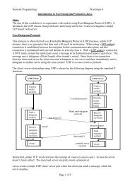
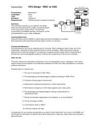
<strong>ARINC</strong> 429 <strong>Tutorial</strong>Bit Oriented <strong>Protocol</strong>sBit Oriented <strong>Protocol</strong>sThe Williamsburg, or "bit oriented", <strong>Protocol</strong> is a system for transferringfiles between <strong>ARINC</strong> units. It was originally defined in <strong>ARINC</strong>Specification 429-12 and expanded in Specifications 429-13 and 14 and isfurther defined in Reference 5. It is currently under revision. It should beused in lieu of the former AIM, file transfer, and maintenance formats usedin Specification 429-11. Normal <strong>ARINC</strong> data messages can be intermixedwith the bit-oriented messages of the Williamsburg <strong>Protocol</strong>.A start up procedure is used to determine the proper protocol fortransferring data. When a system element wants to use the bit-orientedsystem it transmits a message using the latest version of which it is capable.A handshaking process adjusts the protocol to the lowest commondenominator that both sending and receiving systems can use. Currently,two versions of the <strong>Protocol</strong> are available. Version 1 is defined in 429-12and refined in 429-13. Version 2 is defined in 429-14 but was never used.Reference 5 deletes Version 2 and it defines a new Version 3. It redefinesVersion 1 to facilitate the communications of the ACARS ManagementUnit (MU) and the Satellite Data Unit (SDU).The source initiates communications by sending certain predefined codes.If a bit-oriented transfer is desired, the initial code word will be an "ALO"(for Aloha) signal to the potential recipient. The ALO word should besent by any system that supports the protocol just after the system powersup, or performs a re-initialization for any reason. If any sink is capable ofreceiving bit-oriented data it responds with an "ALR" code so that thesource knows that it can transmit to that unit. When a source wants totransmit to a unit capable of handling the protocol, it sends a Request toSend word (RTS), and waits to receive a Clear to Send (CTS). The RTSincludes a Destination Code and a Word Count, which are repeated in theCTS for verification. If the CTS is correct, the source then initiates the filetransfer, following the sequence shown in Figure 8 for version 1. Thelatter version provides the capability of sending a larger file (up to 7LDUs), without needing to renew permission of the sink.Files are transferred in blocks called Link Data Units (LDU) ranging insize from 3 to 255 words. Following receipt of the CTS, the sourceinitiates a Version 1 transfer with a Start of Transmission word (SOT).The SOT includes a file sequence number, a General Format Identifier(GFI), and a LDU Sequence Number. The data words are then sent,followed by the (up to) 255th word which is an End of Transmission(EOT). Each LDU transfer (255 words or less) is terminated by an End ofTransmission Word (EOT). The EOT includes a CRC and identifies theposition of the LDU in the overall file transfer. The sink performs averification process on the EOT, and sends an Acknowledgment Word(ACK) if all tests are passed. The source then sends another CTS, and theprocess is repeated until the last LDU is acknowledged.<strong>ARINC</strong> <strong>Protocol</strong> <strong>Tutorial</strong> 15
Bit Oriented <strong>Protocol</strong>s<strong>ARINC</strong> 429 <strong>Tutorial</strong>AIRLINESOURCE ------->------->ORIGINALDATA FILERTS WORDAIRCRAFTSINKCTS WORD
<strong>ARINC</strong> 429 <strong>Tutorial</strong>Bit Oriented <strong>Protocol</strong>sSYSTEMTable 11. <strong>Systems</strong> Using Bit Oriented Communications and Their Address LabelsSAL(OCT)SYSTEMSAL(OCT)777 CABIN INTERPHONE SYSTEM 152 LOW SPEED DATA LINK (<strong>ARINC</strong> 603) 300747 DFDR AND A330/340 SSFDR 163 FMC 1 300DFDAU (Mandatory Load Functions) 170 FMC 2 301SDU #2 173 DFDAU (AIDS) 302RFU 174 CFDIU 303HGA/HPA TOP/PORT 175 ACARS MU/CMU (724B, 748) 304HGA/HPA STARBOARD 176 WBS 305LGA/HPA 177 TCAS 306GPS/GNSS SENSOR 201 SDU #1 307MCDU 1 220CABIN TELECOMMUNICATIONS UNIT(CTU)MCDU 2 221 HF DATA RADIO/DATA UNIT #1 340MCDU 3 222 HF DATA RADIO/DATA UNIT #2 344PRINTER 1 223 ACESS 360PRINTER 2 224 EFIS 361HIGH SPEED DL (<strong>ARINC</strong> 615) 226 ENGINE INDICATION UNIT 365MCDU 4 230 CABIN TERMINAL 3 372EIVMU 1 234 CABIN TERMINAL 4 373EIVMU 2 235 CABIN TERMINAL 1 374EIVMU 3 236 CABIN TERMINAL 2 375EIVMU 4 237 OMEGA NAV. SYSTEMS 376CABIN VIDEO SYSTEM (AIRSHOW) 266334<strong>ARINC</strong> <strong>Protocol</strong> <strong>Tutorial</strong> 17
CHAPTER 2Other <strong>ARINC</strong> <strong>Protocol</strong>s<strong>ARINC</strong> 419Reference 7, <strong>ARINC</strong> 419 Digital Data System Compendium, describes anumber of digital transmission system building blocks which whereavailable prior to 1984. It provides a synopsis of many protocols thatpredate <strong>ARINC</strong> 429 such as <strong>ARINC</strong> 561, 582, 573 and 575.The reference describes a number of digital transmission systems withvarying standards. Some systems used 32-bit words similar to <strong>ARINC</strong>429; some used major frames of four subframes each consisting of 64, 12-bit words. Still others used 32-bit, rather than 64-bit words. Somemessage frames were 24 bits with three subframes of two BCD words.Some systems did not provide information identifiers; others used 8-bitlabel codes, and another depended on time slots for identifyinginformation. Identification of BCD vs. BNR was provided by a flag bit ineither the 1 st bit or the 4 th bit transmitted. A variety of standard data labelswere adopted.Some electrical interconnections depended on one wire per bit; others usedthe 6 wire system described above while others used a shielded 2 wiretwisted pair or a coaxial cable. Either two state, (HI LO), or three state (HINULL LO) were used. Voltage levels ranged from 18.5 to 10 for the highstate and from (less than) 5 to 1 for the null where used. Digital languagesincluded Gilham code (an example is the altitude encoder for the ATCTransponder), a bit stream you determined in each individual case,International Standards Organization (ISO) Alphabet #5, BCD, and BNR.In some cases there was no error detection or correction, others used bitparity or character parity, or block sequence check. Bit rate varied from384 BPS to 12+ KBPS, and there were many other variations amongsystems.The variability of “standards” doesn’t matter where a single user isinvolved, but is very important when equipment from different suppliersmust interact with each other. Standardization is beneficial not only to theaircraft integrator, but to the equipment supplier who can have greaterassurance of product acceptability so long as it is “on spec”. <strong>ARINC</strong> 429<strong>ARINC</strong> <strong>Protocol</strong> <strong>Tutorial</strong> 19
<strong>ARINC</strong> 453Other <strong>ARINC</strong> <strong>Protocol</strong>sis the most widely applied Digital Data Transmission specification formodern transport aircraft. <strong>ARINC</strong> 429 draws on the experience of 419 butdoes not depend on it.<strong>ARINC</strong> 453Not a formally released specification. See <strong>ARINC</strong> 708.<strong>ARINC</strong> 561/568The need for standardized digital data transmission arose during thedevelopment of <strong>ARINC</strong> Characteristics 561, “Air Transport InertialNavigation System”. <strong>ARINC</strong> 568 uses the same electrical interface as<strong>ARINC</strong> 561.A six-wire system involving 3 pairs of wires, was used in 561. The threepairs served as “clock”, “sync”, and “data” respectively. Non return tozero (NRZ) was employed, and a twelve-volt logic level was transmittedfor a binary 1. The word length was 32 bits. Bits 32 and 31 contained theSSM, and no parity bit was provided. The remaining fields included an 8-bit label and 6 BCD fields, five of 4 bits and one of 2 bits. In 1967 the sixwiresystem was adopted as an industry standard.Figure 9. <strong>ARINC</strong> 561 6-Wire Bit Encoding<strong>ARINC</strong> 573Other standards include <strong>ARINC</strong> 573, a Flight Data Recorder output format.This device sends a continuous data stream of Harvard Bi-Phase encoded12 bit words which is encoded in frames. The data in a frame consists of asnapshot of the many avionics subsystems on the aircraft. Each framecontains the same data at a different snapshot in time.20 <strong>ARINC</strong> <strong>Protocol</strong> <strong>Tutorial</strong>
Other <strong>ARINC</strong> <strong>Protocol</strong>s <strong>ARINC</strong> 575Each frame is broken into four sub-frames. At the start of each sub-frameis a unique sync word that is used by the receiver to synchronize with theincoming data.1 bit cell5v0v1 1 0 0 1 0 1 0Figure 10. Harvard Bi-phase Bit Encoding<strong>ARINC</strong> 575<strong>ARINC</strong> 575 is an older specification very similar to <strong>ARINC</strong> 429 but nowobsolete. It accommodated the Mark 3 Subsonic Air Data System (DADS)with a single twisted pair of wires, which has become the standard in<strong>ARINC</strong> 429. Electrically, <strong>ARINC</strong> 575 is generally compatible with lowspeed <strong>ARINC</strong> 429. Some variants of 575 use a bit rate that is significantlyslower than <strong>ARINC</strong> 429 and are not electrically compatible. Also, in somecases, <strong>ARINC</strong> 575 words use bit 32 as parity (as does <strong>ARINC</strong> 429); inother cases bit 32 is used as data.<strong>ARINC</strong> 582This is an older specification that has many electrical permutations. Thereare 6-wire versions (see <strong>ARINC</strong> 561), 2-wire versions (see <strong>ARINC</strong> 575) aswell as 16-bit, 2-wire versions.<strong>ARINC</strong> 615Special cases of <strong>ARINC</strong> 429 compliant systems also exist. <strong>ARINC</strong> 615(See Reference 8) describes a high-speed data loader to transferinformation to and from on board digital systems. It is a software protocollayered on top of an <strong>ARINC</strong> 429 physical layer. There are two versions ofthe loader. PDL is a portable flight line piece of test equipment and ADLis designed to fit in commercial aircraft instrument panels. Both equipmentare capable of reading and writing to 3½ inch diskettes and transferring<strong>ARINC</strong> <strong>Protocol</strong> <strong>Tutorial</strong> 21
<strong>ARINC</strong> 629Other <strong>ARINC</strong> <strong>Protocol</strong>sdata between the diskettes and a selected airborne computer. The transferscan occur automatically, or via an <strong>ARINC</strong> 429 data bus. Data can be eitheruploaded or downloaded as desired.<strong>ARINC</strong> 629Additional <strong>ARINC</strong> standards are being developed. <strong>ARINC</strong> 629 is used onthe new Boeing 777 Aircraft. It uses a high-speed bi-directional buscapable of either periodic or aperiodic transmissions. Access to the bus iscontrolled by a sophisticated protocol involving wait periods, quiet periodsand other rules. Further details can be found in Reference 9.<strong>ARINC</strong> 708This protocol is specific to airborne weather radar systems. It is used as theoutput from the radar to the radar display. The bus uses 2-wires, issimplex, Manchester encoded and runs at a one-megabit data rate. It wasoriginally based upon a simple derivative of MIL-STD-1553 technology.The data words are 1600 bits long which is composed of one, 64-bit statusword and 512, 3-bit data words.<strong>ARINC</strong> 717<strong>ARINC</strong> 717 supercedes <strong>ARINC</strong> 573 and is used to perform the samefunction. It adds a number of different bit rates and frame sizes. It alsoprovides for an alternate output data stream that is identical to the primary,Harvard Bi-phase encoded stream, except that it is encoded in BPRZformat (the same as <strong>ARINC</strong> 429).22 <strong>ARINC</strong> <strong>Protocol</strong> <strong>Tutorial</strong>
APPENDIX AReferencesList of References• <strong>ARINC</strong> Web Site, http://www.arinc.com• <strong>ARINC</strong> Specification 429P1-15, September 1, 1995• <strong>ARINC</strong> Specification 429P2-15, March 6, 1996• “Principles of Avionics Data Buses”, Editorial Staff of Avionics,Communications Inc., Leesburg, VA• AEEC Letter 97-013/WIL-03, January 24, 1996• <strong>ARINC</strong> Digital Data System Compendium, <strong>ARINC</strong> Report 419-3,November 5, 1984• <strong>ARINC</strong> Airborne Computer Data Loader, <strong>ARINC</strong> Report 615-2, June1, 1991• “<strong>ARINC</strong> 629 P1-4 Multi-Transmitter Data Bus”, “Part1, TechnicalDescription”, December, 1995• Aeronautical Radio, Inc., 2551 Riva Road, Annapolis, MD, 21401• Global Engineering Documents<strong>ARINC</strong> <strong>Protocol</strong> <strong>Tutorial</strong> 23