afdx/arinc 664
afdx/arinc 664
afdx/arinc 664
- No tags were found...

Create successful ePaper yourself
Turn your PDF publications into a flip-book with our unique Google optimized e-Paper software.
List of FiguresFigure 1. AFDX Network 4Figure 2. ARINC 429 Communication Protocol 5Figure 3. MIL-STD-1553 Bus Communication Protocol 5Figure 4. ALOHA Net 6Figure 5. Ethernet Local Area Networks (Broadcast Media) 6Figure 6. Ethernet Frame Format 6Figure 7. Full-Duplex, Switched Ethernet Example 7Figure 8. AFDX versus ARINC 429 architecture 8Figure 9. End Systems and Avionics Subsystems Example 9Figure 10. Sampling Port at Receiver 10Figure 11. Queuing Port at Receiver 10Figure 12. Format of Ethernet Destination Address in AFDX Network 11Figure 13. Packet Routing Example 11Figure 14. Message Sent to Port 1 by the Avionics Subsystem 12Figure 15. Ethernet Frame with IP and UDP Headers and Payloads 12Figure 16. A and B Networks 13Figure 17. AFDX Frame and Sequence Number 13Figure 18. Receive Processing of Ethernet Frames 13Figure 19. Three Virtual Links Carried by a Physical Link 14Figure 20. Virtual Link Scheduling 15Figure 21. Virtual Link Scheduling 15Figure 22. Role of Virtual Link Regulation 16Figure 23. Two Message Structures 17Figure 24. ARINC <strong>664</strong> Message Structures 18Figure 25. AFDX Tx Protocol Stack 19Figure 26. AFDX Rx Protocol Stack 20Figure 27. Ethernet Source Address Format 21Figure 28. IP Header Format 21Figure 29. IP Unicast Address Format 21Figure 30. IP Multicast Address Format 21Figure 31. UDP Header Format 22
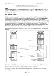
Chapter 1 OverviewThe AntecedentsMoving information between avionics subsystems on boardan aircraft has never been more crucial, and it is here thatelectronic data transfer is playing a greater role than everbefore. Since its entry into commercial airplane service on theAirbus A320 in 1988, the all-electronic fly-by-wire system hasgained such popularity that it is becoming the only controlsystem used on new airliners.But there are a host of other systems — inertial platforms,communication systems, and the like — on aircraft, thatdemand high-reliability, high-speed communications, as well.Control systems and avionics in particular, rely on havingcomplete and up-to-date data delivered from source to receiverin a timely fashion. For safety-critical systems, reliablereal-time communications links are essential.That is where AFDX comes in. Initiated by Airbus in the evolutionof its A380 Aircraft, they coined the term, AFDX, for AvionicsFull-DupleX, switched Ethernet. AFDX brings a number ofimprovements such as higher-speed data transfer — and withregard to the host airframe — significantly less wiring, therebyreducing wire runs and the attendant weight.What is AFDX?Avionics Full DupleX Switched Ethernet (AFDX) is a standardthat defines the electrical and protocol specifications (IEEE802.3 and ARINC <strong>664</strong>, Part 7) for the exchange of data betweenAvionics Subsystems. One thousand times faster thanits predecessor, ARINC 429, it builds upon the original AFDXconcepts introduced by Airbus.One of the reasons that AFDX is such an attractive technologyis that it is based upon Ethernet, a mature technologythat has been continually enhanced, ever since itsinception in 1972. In fact, the commercial investment andadvancements in Ethernet have been huge compared say,to ARINC 429, MIL-STD-1553, and other specialized datacommunicationstechnologies.As shown in Figure 1, an AFDX system comprises the followingcomponents:Avionics Subsystem: The traditional Avionics Subsystemson board an aircraft, such as the flight control computer,global positioning system, tire pressure monitoringsystem, etc. An Avionics Computer System provides acomputational environment for the Avionics Subsystems.Each Avionics Computer System contains an embeddedEnd System that connects the Avionics Subsystems to anAFDX Interconnect.AFDX End System (End System): Provides an “interface”between the Avionics Subsystems and the AFDX Interconnect.Each Avionics Subsystem the End System interfaceto guarantee a secure and reliable data interchange withother Avionics Subsystems. This interface exports an applicationprogram interface (API) to the various AvionicsSubsystems, enabling them to communicate with eachother through a simple message interface.AFDX Interconnect: A full-duplex, switched Ethernet interconnect.It generally consists of a network of switchesthat forward Ethernet frames to their appropriate destinations.This switched Ethernet technology is a departurefrom the traditional ARINC 429 unidirectional, point-topointtechnology and the MIL-STD-1553 bus technology.Avionics Computer SystemControllersSensorsActuatorsAvionicsSubsystemEndSystemAFDXEndSystemInterconnectControllersSensorsActuatorsAvionicsSubsystemEndSystemGatewayInternetAvionics Computer SystemAvionics Computer SystemFigure 1. AFDX Network
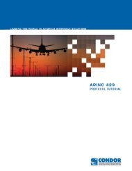
As shown in the example in Figure 1, two of the End Systemsprovide communication interfaces for three avionics subsystemsand the third End System supplies an interface for aGateway application. It, in turn, provides a communicationspath between the Avionics Subsystems and the external IPnetwork and, typically, is used for data loading and logging.The following sections provide an overview of the AFDX architectureand protocol. But first we briefly review two of thetraditional avionics communications protocols.Other Avionics BusesThis section compares AFDX to two earlier Avionics data communicationprotocols: ARINC 429 and MIL-STD-1553.ARINC 429SourceReceiverReceiverBit rates are either 100 Kbps or 12.5 Kbps32-bit messagesReceiverReceiverMIL-STD-1553Bit-rate 1 Mbps20-bit data wordMIL-STD 1553 DATA BUSBC RT RT RT RTFigure 3. MIL-STD-1553 Bus Communication ProtocolMIL-STD-1553 (see Figure 3) implements a bus architecturein which all the devices attached to the bus are capable ofreceiving and transmitting data. The Avionics subsystems attachto the bus through an interface called a remote terminal(RT). The Tx and Rx activity of the bus is managed by a buscontroller, that acts to ensure that no two devices ever transmitsimultaneously on the bus. The communication is halfduplex and asynchronous. For more information, refer to theGE Fanuc Embedded Systems “MIL-STD-1553 Tutorial”.Figure 2. ARINC 429 Communication ProtocolARINC 429 implements a single-source, multi-drop bus withup to 20 receivers (see Figure 2). Messages consist of 32-bitwords with a format that includes five primary fields. TheLabel field determines the interpretation of the fields in the remainderof the word, including the method of translation. Thepoint to multi-point property of ARINC 429 requires the Avionicssystem to include an ARINC 429 bus for each pair-wisecommunication. Refer to the GE Fanuc Embedded SystemsARINC Tutorial for more details.
Chapter 2 EthernetEthernetThis chapter provides a brief description of the origins ofEthernet, the Ethernet frame format and the role of switchedEthernet in avionics applications.ALOHA NetIn 1970, the University of Hawaii deployed a packet radiosystem called the “ALOHA network” [Norman Abramson; seeFigure 4] to provide data communications between stationslocated on different islands. There was no centralized controlamong the stations; thus, the potential for collisions (simultaneoustransmission by two or more stations) existed.StationEtherStationHostFigure 5. Ethernet Local Area Networks (Broadcast Media)The Ethernet Protocol1. If you have a message to send and the medium is idle,send the message.2. If the message collides with another transmission, trysending the message later using a suitableback-off strategy.Issues• No central coordination.Coaxial Cable (Bus Architecture)HostHost• Collisions lead to non-deterministic behavior.HostThe ALOHA ProtocolFigure 4. ALOHA Net1. If you have a message to send, send the message, and2. If the message collides with another transmission, tryresending the message later using a back-off strategy.Issues• No central coordination.Station• Collisions lead to non-deterministic behavior.Ethernet Local Area Networks (Broadcast Media)In 1972, Robert Metcalfe and David Boggs at Xerox Palo AltoResearch Center built upon the ALOHA network idea and useda coaxial cable as the communication medium and inventedEthernet (see Figure 5). Ethernet is similar to the ALOHAprotocol in the sense that there is no centralized control andtransmissions from different stations (hosts) could collide.The Ethernet communication protocol is referred to as “CSMA/CD” (Carrier Sense, Multiple Access, and Collision Detection).Carrier Sense means that the hosts can detect whether themedium (coaxial cable) is idle or busy. Multiple Access meansthat multiple hosts can be connected to the common medium.Collision Detection means that, when a host transmits,it can detect whether its transmission has collided with thetransmission of another host (or hosts). The original Ethernetdata rate was 2.94Mbps.Ethernet Using Category 5 UTP Copper Twisted PairsThe most common electrical form of Ethernet today is basedon the use of twisted pair copper cables. Typically, cables arepoint-to-point, with hosts directly connected to a switch. Inthe case of Fast Ethernet (100Mbps), two pairs of Category 5UTP copper wire are used for Tx and Rx, respectively. In thecase of transmission, each 4-bit nibble of data is encodedby 5 bits prior to transmission. This is referred to as “4B/5Bencoding” and results in a transmission clock frequency of125Mbps, since 5 bits are sent for every 4 bits of data. Sincethere are twice as many 5-bit patterns as 4-bit ones, it ispossible to ensure that every transmitted pattern is able toprovide good clock synchronization (not too many 0’s or 1’sin a row) for reliable transmission of data. Some of the 5-bitpatterns are used to represent control codes.PreambleSFDDestinationAddressSourceAddressTypePayloadbyte 7 1 6 6 2 46 - 1500 4 12Ethernet FrameFigure 6. Ethernet Frame FormatEthernet Frame FormatAs Figure 6 illustrates, IEEE 802.3 defines the format of anEthernet transmission to include a 7-byte Preamble, a StartFrame Delimiter (SFD), the Ethernet frame itself, and anInter-Frame Gap (IFG) consisting of at least 12 bytes of idlesymbols. The Ethernet frame begins with the Ethernet header,FCSIFG
which consists of a 6-byte destination address, followed by a6-byte source address, and a type field. The Ethernet payloadfollows the header. The frame concludes with a Frame CheckSequence (FCS) for detecting bit errors in the transmittedframe, followed by an IFG. The length of an Ethernet framecan vary from a minimum of 64 bytes to a maximum of1518 bytes.Ethernet communication (at the link level) is connectionless.Acknowledgments must be handled at higher levels in theprotocol stack.Full-duplex, Switched EthernetThe ScenarioHalf-duplex Mode Ethernet is another name for the originalEthernet Local Area Network discussed earlier. As we explained,there is an issue when multiple hosts are connectedto the same communication medium as is the case withcoaxial cable, depicted in Figure 5, and there is no centralcoordination. It is possible for two hosts to transmit “simultaneously”so that their transmissions “collide.” Thus there is aneed for the hosts to be able to detect transmission collisions.When a collision occurs (two or more hosts attempting totransmit at the same time), each host has to retransmit itsdata. Clearly, there is a possibility that they will retransmit atthe same time, and their transmissions will again collide.Doing Away with ContentionTo do away with contention (collisions), and hence theindeterminacy regarding how long a packet takes to travelfrom sender to receiver, it is necessary to move to Full-duplexSwitched Ethernet. Full-duplex Switched Ethernet eliminatesthe possibility of transmission collisions like the ones thatoccur when using Half-duplex Based Ethernet. As shown inFigure 7, each Avionics Subsystem— autopilot, heads-up display,etc. — is directly connected to a Switch over a full-duplexlink that comprises two twisted pairs — one pair for transmit(Tx) and one pair for receive (Rx). (The switch comprises all thecomponents contained in the large box.) The switch is able tobuffer packets for both reception and transmission.Now, let’s look at what goes on within the switch, as shownin Figure 7.SwitchForwarding TableI/O Processing Unit(CPU)To avoid this phenomenon, each host selects a random transmissiontime from an interval for retransmitting the data. If acollision is again detected, the hosts selects another randomtime for transmission from an interval that is twice the sizeof the previous one, and so on. This is often referred to as thebinary exponential backoff strategy.RxBufferMemory BusTxBufferRxBufferTxBufferRxBufferTxBufferSince there is no central control in Ethernet and in spite of therandom elements in the binary exponential backoff strategy,it is theoretically possible for the packets to repeatedly collide.What this means is that in trying to transmit a single packet,there is a chance that you could have an infinite chain of collisions,and the packet would never be successfully transmitted.EndSystemAutopilotEndSystemHeads-upDisplayEndSystemOtherSystems,etc.Full DuplexLinksAvionicsSubsystemsTherefore, in half-duplex mode it is possible for there to bevery large transmission delays due to collisions. This situationis unacceptable in an avionics data network.So, what was required (and what was implemented in AFDX)was an architecture in which the maximum amount of time itwould take any one packet to reach its destination is known.That meant ridding the system of contention.Figure 7. Full-Duplex, Switched Ethernet ExampleThe Rx and Tx buffers in the switch are both capable ofstoring multiple incoming/outgoing packets in FIFO (firstin,first out) order. The role of the I/O processing unit (CPU)is to move packets from the incoming Rx buffers to theoutgoing Tx buffers. It does this by examining each arrivingpacket that is next in line in the Rx buffer to determine itsdestination address (virtual link identifier) and then goes to
the Forwarding Table to determine which Tx buffers are toreceive the packet. The packet is then copied into the Tx buffers,through the Memory Bus, and transmitted (in FIFO order)on the outgoing link to the selected Avionic Subsystem or toanother switch. This type of switching architecture is referredto as store and forward.Consequently, with this full-duplex switch architecture thecontention encountered with half-duplex Ethernet is eliminated,simply because the architecture eliminates collisions.Theoretically, a Rx or Tx buffer could overflow, but if the bufferrequirement in an avionics system are sized correctly, overflowcan be avoided.There are no collisions with full-duplex switched Ethernet,but packets may experience delay due to congestion inthe switch.But in the case of AFDX, as shown in Figure 8b, each signalis connected to the switch only once so that no matter howmany subsystems require the azimuth signal from the inertialplatform, they need not be connected individually to theinertial platform.With ARINC 429, a transmitter can fan out to only 20 receivers.With AFDX, the number of fan-outs from the inertialplatform is limited only by the number of ports on the switch.Also, by cascading switches, the fan-out can be easily increasedas needed.Azimuth dataTwisted-pair copper wireTransmitter Receiver ReceiverReceiverInstead of collisions and retransmissions, switching architecturemay result in jitter, due to the random delay introducedby one packet waiting for another to be transmitted. Theextent of jitter introduced by an End System and Switch mustbe controlled if deterministic behavior of the overall AvionicsSystem is to be achieved.InertialPlatformARINC 429AutopilotHeads-upDisplayOtherSystems,etc.Simplex100 Kbps (maximum)Up to 20 receiversReducing Wire Runs and WeightIn addition to the enhancements already described, AFDXdelivers some additional benefits, compared to ARINC 429.Figure 8 shows some distinctions between ARINC 429 andAFDX. In ARINC 429, a twisted pair must link every device thatreceives the azimuth signal form the inertial platform. Thepoint-to-multi-point and unidirectional properties of ARINC429 means that the avionics system must include an ARINC429 bus for each communication path. In a system with manyend points, point-to-point wiring is a major overhead. This canlead to some huge wiring harnesses, with the added weightthat goes along with them.Two pairscategory 5 UTPtwisted-paircopper wireAFDXEndSystemInertialPlatformSwitchEndSystemHeads-upDisplayEndSystemOtherSystems,etc.Full duplex100 Mbps (maximum)Number of connectionsgoverned by numberof switch portsFigure 8. AFDX versus ARINC 429 architecture
Chapter 3 End Systems and Avionics SubsystemsEnd Systems and Avionics SubsystemsAs Figure 9 shows, an Avionics computer system connectsto the AFDX network through an End System. In general, anAvionics computer system is capable of supporting multipleAvionics subsystems. Partitions provide isolation between Avionicssubsystems within the same Avionics computer system.This isolation is achieved by restricting the address space ofeach partition and by placing limits on the amount of CPUtime allotted to each partition. The objective is to ensure thatan errant Avionics subsystem running in one partition will notaffect subsystems running in other partitions.Avionics applications communicate with each other by sendingmessages using communication ports. The specificationof an operating system API for writing portable avionics applicationscan be found in ARINC 653. In particular, ARINC 653defines two types of communications ports – sampling andqueuing ports. Accordingly, it is necessary that End Systemsprovide a suitable communications interface for supportingsampling and queuing ports. The AFDX ports, defined inARINC <strong>664</strong>, Part 7, include sampling, queuing and SAP ports.The AFDX sampling and queuing ports correspond to ARINC653 sampling and queuing ports, respectively. AFDX introducesa third port type called a Service Access Point (SAP)port. SAP ports are used for communications between AFDXsystem components and non-AFDX systems. More about thisin the next chapter.End Systems are identified using two 8-bit quantities: aNetwork ID and an Equipment ID. These may be combinedinto a single 16-bit quantity. As we shall see, the End Systemidentification is used in forming source MAC addresses andunicast IP addresses.Avionics Computer SystemControllersAvionicsSubsystemPartition 1SensorsAvionicsSubsystemPartition 2EndSystemAFDXSwitchAFDXNetworkActuatorsAvionicsSubsystemPartition 3ARINC 653Sampling portsQueuing portsARINC <strong>664</strong>, Part 7AFDX communications portsSampling portsQueuing portsService access point portFigure 9. End Systems and Avionics Subsystems Example
Chapter 4 AFDX Communications PortsAFDX Communications PortsAvionics subsystems use communications ports to sendmessages to each other. Communication ports, which aretypically part of the operating system API, provide a programmingmechanism for sending and receiving messages. Twotypes of communications ports play a role in Avionics subsystems:sampling and queuing ports.AFDX End Systems must provide both sampling and queuingport services, as described in ARINC 653.As Figure 10 and Figure 11 show, sampling and queuing portsdiffer mainly in reception. A sampling port has buffer storagefor a single message; arriving messages overwrite themessage currently stored in the buffer. Reading a messagefrom a sampling port does not remove the message from thebuffer, and therefore it can be read repeatedly. Each samplingport must provide an indication of the freshness of the messagecontained in the port buffer. Without this indication, itwould be impossible to tell whether the transmitting Avionicssubsystem has stopped transmitting or is repeatedly sendingthe same message.Arriving messageoverwrites thecurrent messagestored in theport bufferArriving messageis appended tothe queueM1FreshnessIndicatorFigure 10. Sampling Port at ReceiverM1M1M1Figure 11. Queuing Port at ReceiverApplication readinga message from theport does not removethe messageApplication readinga message fromthe port removesthe messageA queuing port has sufficient storage for a fixed number ofmessages (a configuration parameter), and new messagesare appended to the queue. Reading from a queuing portremoves the message from the queue (FIFO).Typical programming interfaces for sending and receivingmessages are as follows:• Send_Msg(port_ID, message)• Recv_Msg(port_ID, message)The port_ID identifies the communication port, and the messageargument points to a buffer that either contains themessage to be sent or is available to receive a new messagefrom the port.10
Chapter 5 Virtual Links: Packet Routing in AFDXVirtual LinksIn a traditional Ethernet switch, incoming Ethernet framesare routed to output links based on the Ethernet destinationaddress. In AFDX, a 16-bit value called a Virtual Link IDis used to route Ethernet frames in an AFDX network. Figure12 provides the format of the Ethernet destination addressin an AFDX network.The switches in an AFDX network are “configured” to routean incoming Ethernet frame to one or more outgoing links.An important property of an AFDX network is that Ethernetframes associated with a particular Virtual Link ID must originateat one, and only one, End System. The AFDX switchesare configured to deliver frames with the same Virtual LinkID to a predetermined set of End Systems. Thus, a virtual linkoriginates at a single End System and delivers packets to afixed set of End Systems; this is analogous to an ARINC 429multi-drop bus.In the example in Figure 13, when the Source End System(1) sends an Ethernet frame with a Virtual Link ID (VLID) =100 to the network, the AFDX switches deliver the frame toa predetermined set of destination End Systems (2 and 3).More than one virtual link can originate at an End System,and each virtual link can carry messages from one or morecommunication ports.48 bitsConstant Field: 24 bits“0000 0011 0000 0000 0000 0000 0000 0000”Virtual Link ID16-bit Unsigned IntegerFigure 12. Format of Ethernet Destination Address in AFDX NetworkEndSystem 1VLID = 100VLID = 100VLID = 100EndSystem 2EndSystem 3Figure 13. Packet Routing Example11
Chapter 6 Message FlowsMessage FlowsWhen an application sends a message to a communicationsport, the source End System, the AFDX network, and the destinationEnd Systems are configured to deliver the messageto the appropriate receive ports.Figure 14 shows a message M being sent to Port 1 by the Avionicssubsystem. End System 1 encapsulates the message inan Ethernet frame and sends the Ethernet frame to the AFDXSwitched Network on Virtual Link 100 (the Ethernet destinationaddress specifies VLID 100). The forwarding tables in thenetwork switches are configured to deliver the Ethernet frameto both End System 2 and End System 3. The End Systemsthat receive the Ethernet frame are configured so that theyare able to determine the destination ports for the messagecontained in the Ethernet frame. In the case shown in Figure14, the message is delivered by End System 2 to port 5 and byEnd System 3 to port 6.The information used by the destination End System to findthe appropriate destination port for the message is containedin headers within the Ethernet payload.Figure 15 shows the headers that make up the Ethernet payload.The Ethernet payload consists of the IP packet (headerand payload). The IP packet payload contains the UDP packet(header and payload), which contains the message sent bythe Avionics subsystem. The Pad is necessary only when theUDP payload is smaller than 18 bytes; in this case, the padplus the UDP payload will equal 18 bytes. With UDP payloadsgreater than or equal to 18 bytes, there is no Pad field. Notethat the diagram applies only to UDP payloads that have notbeen fragmented among multiple IP payloads. An importantfunction of the IP header is to provide fragmentation controlfor large UDP packets.The IP header contains a destination End System Identificationand partition identifiers or is a multicast address. In thelatter case, the IP destination address contains the VirtualLink ID (the Virtual Link ID in the Destination Ethernet address).The UDP header contains both source and destinationUDP port numbers. In general, there is enough information inthese headers for an End System to determine the destinationport for the message. Similarly, sufficient information associatedwith a transmitting AFDX communication port exists forthe source End System to construct the appropriate headerswhen building the Ethernet frame that contains the message.Appendix A, “AFDX Frame Addressing and Header Structures”,provides additional details on the contents and format of theEthernet frames.Avionics Computer SystemAFDXNetworkAvionics Computer SystemMPort 1 End100 MSystem 2 Port 5Port 2EndSystem 1100 MMPort 3100 MAvionics Computer SystemEndSystem 3 Port 6 MFigure 14. Message Sent to Port 1 by the Avionics SubsystemEthernet HeaderIP HeaderUDPHeadersUDP PayloadAvionics SubsystemMessagePadFCSbyte 14 20 8 0 --- 14724UDP Header and PayloadIP Header and PayloadFigure 15. Ethernet Frame with IP and UDP Headers and Payloads12
Chapter 8 Virtual Link IsolationVirtual Link IsolationAs mentioned previously, the 100 Mbps link of an End Systemcan support multiple virtual links. These virtual links share the100 Mbps bandwidth of the physical link. Figure 19 showsthree virtual links being carried by a single 100 Mbps physicallink. The figure also shows that the messages sent on AFDXPorts 1, 2, and 3 are carried by Virtual Link 1. Messages senton AFDX Ports 6 and 7 are carried by Virtual Link 2, and messagessent on AFDX Ports 4 and 5 are carried by Virtual Link 3.Port 1Port 1Port 1Port 1Port 1VLID 3VLID 1Port 1VLID 2Port 1100 MbpsEthernet LinkFigure 19. Three Virtual Links Carried by a Physical LinkJust as partitions are used to isolate Avionics subsystemsfrom one another, a similar mechanism is required to isolateindividual virtual links, in order to prevent the traffic on onevirtual link from interfering with traffic on other virtual linksusing the same physical link. This is done by limiting the rateat which Ethernet frames can be transmitted on a virtual linkand by limiting the size of the Ethernet frames that can betransmitted on a virtual link.Each virtual link is assigned two parameters:• Bandwidth Allocation Gap (BAG), a value ranging inpowers of 2 from 1 to 128 milliseconds• Lmax, the largest Ethernet frame, in bytes, that can betransmitted on the virtual linkThe table below indicates the allowable values for the BAGand the corresponding frequencies.Table 1. Allowable BAG ValuesBAGmillisecondsHz1 10002 5004 2508 12516 62.532 31.2564 15.625128 7.8125Choosing the BAG and Lmax for a Virtual LinkThe choice of BAG for a particular virtual link depends onthe requirements of the AFDX ports that are being providedlink-level transport by the virtual link. For example, supposean Avionics subsystem is sending messages on three AFDXcommunications ports that are being carried by the samevirtual link. Let’s assume the message frequencies on theports are 10 Hz, 20 Hz, and 40 Hz, respectively. The totalfrequency of the combined messages (they will be combinedon the same virtual link) is 70 Hz. The average period of themessage transmissions is 14.4ms. Accordingly, to provideadequate bandwidth on the virtual link, we should select aBAG that is less than 14.4 ms. The first available BAG is 8 ms,which corresponds to a frequency of 125 Hz. With a BAG of8 ms, we are guaranteed that the virtual link is able to transportthe combined messages from the three ports withoutany backlog.The source End System is required to enforce BAG restrictionsfor each outgoing virtual link. A number of virtual link schedulingalgorithms can be used by the End System.Lmax should be chosen to accommodate the largest Ethernetframe to be transmitted by these ports on the virtual link.The BAG represents the minimum interval in millisecondsbetween Ethernet frames that are transmitted on the virtuallink. For example, if a virtual link with VLID 1 has a BAG of 32milliseconds, then Ethernet packets are never sent faster thanone packet every 32 milliseconds on VLID 1. If VLID 1 has anLmax of 200 bytes, then the maximum bandwidth on VLID 1is 50,000 bits per second (200* 8*1000/32).14
Chapter 10 JitterJitterVirtual Link scheduling consists of two components: packetregulation and multiplexing.Figure 22 shows the role of the Virtual Link Regulators inpacing the frames from the virtual link queues to createzero-jitter output streams. The Virtual Link Scheduler is alsoresponsible for multiplexing the regulator outputs into theRedundancy Management Unit for replication and transmissionon the physical links.The outputs of the Regulator consist of regulated streamsof Ethernet frames. Jitter is introduced when the Regulatoroutputs are combined by the Virtual Link Scheduler MUX;Ethernet frames arriving at input to the MUX at the same timewill experience queuing delay (jitter).Virtual Link 100Virtual Link 200RegulatorBAG = 16Selects framesfor transmissionReplicatesEthernet framesPhysicalLinkRegulatorBAG = 32Virtual LinkSchedulerRedundancyManagementVirtual Link 300PhysicalLinkRegulatorBAG = 4Regulator InputRegulator Output1 23 4 1234BAGBAGBAGBAGBAGBAG1234 1234BAGBAGBAGBAGBAGBAGFigure 22. Role of Virtual Link Regulation16
Chapter 11 AFDX Message StructuresIntroductionAvionics subsystem designers are reasonably free to choosethe message structure that bests suits the Avionics application.The messages are contained in the payload of the UDPpacket. In general, the interpretation of the messages isdetermined by agreement between the Avionics applications.ARINC <strong>664</strong>, Part 7, identifies two types of message structures:explicit and implicit. Explicit message structuresinclude format information that enables the receiver tocorrectly interpret the data. Implicit message structures donot contain any descriptive information to aid the receiverin interpreting the data; consequently, they use networkbandwidth more efficiently.This section discusses the ARINC <strong>664</strong> Implicit MessageStructure formats. Since there is no explicit format informationcontained in an implicit message structure, the Avionicsapplication needs a way to identify the message format ofthe received data. This is accomplished by associating implicitmessage structures with an AFDX receive port. The applicationassociates the message structure based on the UDP portnumber where the message is received.With the Internet, certain well-known UDP port numbers correspondto specific applications: port 69 is used by the TrivialFile Transport Protocol (TFTP); port 80 is used by the HypertextTransport Protocol (HTTP), and so on. An Internet AssignedNumber Authority (IANA) manages the space of UPD portnumbers. UPD port numbers fall into three groups:• Assigned port numbers (well-known ports): 0–1023• Registered port numbers: 1024–4951• Dynamic/Private port numbers: 49152–65535Although AFDX/ARINC <strong>664</strong> is a closed network, UDP portnumbers should be selected from the Dynamic/Private rangeof numbers. The reason for this is that there could be potentialconflicts with the standard port number assignmentswhen a gateway is used to communicate between the AFDXnetwork and the Internet.Implicit Message StructuresARINC <strong>664</strong>, Part 7, presents a more complete description ofthe format of implicit message structures. A limited number ofdata types are defined, including the following:• Signed_32 Integer• Signed_64 Integer• Float_32• Float_64• Boolean• String• Opaque DataThe standard also requires that the primitive data types bealigned on their natural boundaries. For example, Float_64must be aligned on a 64-bit boundary. Address 0 is consideredthe beginning of the UDP payload; all alignments arerelative to Address 0.The first 4 bytes of the message structure are reserved. Afterthis, the basic message structure consists of a 4-byte wordcalled the Functional Status Set, followed by up to four datasets. The basic message structure can be repeated an arbitrarynumber of times to form the message structure. Figure23 depicts two message structures. The one on the left consistsof two data sets, Data Set 1 and Data Set 2. The FunctionalStatus Set has two functional status bytes, FS1 and FS2,which correspond to the Data Sets 1 and 2, respectively.FS1ReservedFS2Data Set 1Data Set 2AFDX Message StructureFunctional Status (FS)– No Data– Normal Operation– Functional Test– No Computed DataFigure 23. Two Message StructuresReservedFS1 FS2 FS3 FS4FS5Data Set 1Data Set 2Data Set 3Data Set 4Data Set 5ARINC <strong>664</strong>Message Structure17
The functional status of each data set is encoded in the correspondingFunctional Status byte. There are four possiblestates: No Data, Normal Operation, Functional Test, and NoComputed Data. Clearly, the data must be grouped into datasets so that the functional status applies to all the data in thedata set.ReservedReservedFS-DS1 unused unusedunusedThe message structure depicted above on the right consistsof two basic message structures and a total of five data setsand five corresponding functional statuses.Data Set 1A429 Label 010 - Present Position (Lat)ARINC 429 LabelsFigure 24 shows how ARINC 429 data can be accommodatedusing the ARINC <strong>664</strong> message structures. The opaque primitivedata type is used so that the interpretation of the data isleft up to the application (as usual).ReservedReservedFS-DS1 FS-DS2 unusedunusedA429 Label 010 - Present Position (Lat)Data Set 1A429 Label 011- Present Position (Long)Data Set 1A429 Label 012 - Ground SpeedA429 Label 076- GNSS AltitudeFigure 24. ARINC <strong>664</strong> Message Structures18
Chapter 12 The AFDX Protocol StackThe AFDX Protocol StackThis tutorial concludes with a description of the overall AFDXprotocol stacks for transmission and reception. The protocollayers are divided into AFDX communications services, UDPtransport layer, and link level (virtual link) services.TransmissionThe Tx protocol begins with a message being sent to anAFDX port. The UDP transport layer is responsible for addingthe UDP header, which includes the appropriate source anddestination UDP port numbers. These numbers are, in mostcases, determined by the system configuration and are fixedfor each AFDX communications port. In the case of a SAPport, the application specifies the IP and UDP destination addressesdynamically.The IP network layer receives the UDP packet and determineswhether it needs to be fragmented. The IP network layer usesthe appropriate virtual link’s Lmax to determine whetherfragmentation is necessary. The IP header is added, and IPchecksum is calculated for each fragment. The IP layer addsthe Ethernet header and enqueues the Ethernet frame in theappropriate sub-VL queue. The (virtual) link layer is responsiblefor scheduling the Ethernet frames for transmission, addingthe sequence numbers (on a per-VL basis), and passingthe frames to the Redundancy Management Unit, where theframes are replicated (if necessary) and the Ethernet sourceaddress is updated with the physical port ID on which theframe is transmitted.End System Tx PacketsAFDX ServicesMessage written to AFDX portMessageUDPTransport LayerUDP HeaderUDP HeaderMessageIP FragmentationIP Network LayerAdd IP ChecksumAdd Ethernet HeaderIP HdrOne or more packets asa result of IP fragmentationIP HdrEthernet HdrSub VL queueVL Scheduler(Regulator)Link Level(Virtual Links)RedundancyManagementEthernet HdrSeq #Network AAdd “Net A” to Ethernetsource addressNetwork BAdd “Net B” to Ethernetsource addressTransmit Ethernetframe with FCSTransmit Ethernetframe with FCSFigure 25. AFDX Tx Protocol Stack19
ReceptionReception is the reverse of transmission. The process startswith the reception of an Ethernet frame, which is checked forcorrectness using the Frame Check Sequence (FCS). If thereis no error, the FCS is stripped and the AFDX frame is passedthrough Integrity Checking and Redundancy Management.These steps are carried out at the (virtual) link level. The resultingIP packet is passed on to the IP network level.The network level is responsible for checking the IP checksumfield and the UDP packet reassembly, if necessary. The UDPpacket is passed to the UDP transport layer to deliver (DE-MUX) the AFDX message to the appropriate UDP port.End System Rx PacketsEthernet HdrFCSErrorsRx ControllerEthernet Hdr Seq #Link Level(Virtual Links)ErrorsIntegrety CheckDrop packetRedundancyManagementIP HdrErrorIP ChecksumIP Network LayerYesICMPNoPacketcomplete?YesYesIP FragmentationThere is direct mappingonly if there is noIP fragmentationUDP HeaderMessageUDPTransport LayerDEMUXMessageAFDX Port ServicesAFDX Rx Port QueuePotential buffer overflowFigure 26. AFDX Rx Protocol Stack20
Appendix A AFDX Frame Addressing and Header StructuresEthernet AddressingConstant Field: 24 bits User-Defined ID Interface ID0000 0010 0000 0000 0000 0000 nnnn nnnn nnnn nnnn nnnn nnnn mmm0 0000Network IDnnnn nnnnEquipment IDnnnn nnnnFigure 27. Ethernet Source Address FormatIP Header Format and AddressingLengthFragmentationControlChecksumSourceAddressDestinationAddressbytes 12 4 4IP HeaderFigure 28. IP Header FormatClass A + Private IP User-Defined ID Partition ID0 000 1010 nnnn nnnn nnnn nnnn nnnn nnnn xxx n 0000Network IDnnnn nnnnEquipment IDnnnn nnnnFigure 29. IP Unicast Address FormatClass D1110 0000 1110 000IP Multicast IdentifierVirtual Link IdentifierFigure 30. IP Multicast Address Format21
UDP Header FormatUDP HeaderUDP PayloadAFDX Message FormatSource PortNumberDestinationPort IDPayloadLengthChecksumbytes 2 222UDP Header FormatFigure 31. UDP Header Format22
Appendix B Referenced DocumentsReference ListDocument NameARINC <strong>664</strong>, Aircraft Data Network, Part 7 –Avionics Full Duplex Switched Ethernet (AFDX) NetworkSourceARINC 05-005/ADN-3923
GE Fanuc Embedded SystemsInformation CentersAmericas:1 800 322 3616 or 1 256 880 0444©2007 GE Fanuc Embedded Systems. All Rights Reserved.All other brands or names are property of their respective holders.02.07 GFT-640
Rugged InsightSpecial Edition - GE MIL/Aero Product News8-Kern PowerPC OpenVPX Single-Board-ComputerGE Intelligent Platforms neuer SBC bietet mit Freescales P4080CPU mit 8 PowerPC e500mc Kernen, 4 GbE, 3 PCIe und 2 SRIOPorts sowie 8 GB DDR3 RAM eine überragende PerformanceDistributorIntelligent PlatformsInhalt:Neuer 8-Kern OpenVPX PowerPC SBCDer SBC612 SBC ist in verschiedenen Ausführungen mit Luft- oder Kontaktkühlung bis -40...+85°C erhältlich.nBasierend auf Freescales P4080 bietet der SBC612 mit bis zu acht PowerPC Prozessorkernengegenüber Dual- und Quad-Core Boards einen riesigen Sprung in punctoRechenleistung und Datendurchsatz. In Kombination mit seiner umfangreichen undflexiblen Palette an I/O-Optionen, ist der SBC612 auf MIL- und Aero-Applikationen zugeschnitten,die einen hohen Bedarf an Rechenleistung haben.Das Herz des SBC612 bildet Freescales griffe von Außen erreicht und sowohl Daten,neuer QorIQ-P4080 Prozessor mit 8 bis zu als auch Programmcode vor dem Zugriff1,5 GHz getakteten e500mc-Kernen und durch Unbefugte geschützt.max. 8 GB Dual-Channel DDR3 Speicher.EigenschaftenDie acht CPU-Kerne bieten SystementwicknFüreine adäquate Kommunikation sorlerneine herausragende Flexibilität, untergenvier x4 RapidIO-Links, vier x4 PCIstützen symmetrische und asymmetrischeExpress Schnittstellen und 4 GbE-PortsMultiprozessor-Architekturen und bieten dieMöglichkeit, gleichzeitig mehrere Betriebs- n2 Steckplätze für wahlweise XMC- odersysteme auf demselben Board zu betrei- PMC-Module mit Rear-I/O Option bietenben. Diese Flexibilität bietet bei der Migrati- grenzenlose Erweiterungsmöglichkeitenon älterer Multi-CPU Anwendungen in einenEin AFIX-Steckplatz kann z.B. mit 3Dneue,durchgängige OpenVPX-System-Grafik-, SCSI-, MIL-STD-1533- und Digiarchitekturgroße Vorteile.tal-I/O-Modulen bestückt werdenDie gerade mal 30 Watt Verlustleistung desnDer SBC612 ist in allen fünf MIL-Standardneuen 8-Kernprozessors liegt auf dem Niveaufrüherer Dual-Core-Prozessoren.Rugged-Levels lieferbar und unterstütztdie Deployed-Test-Software (BIT u. BCS)Darüber hinaus bietet der QorIQ P4080 zahlreichetechnische Innovationen, wie z.B. die nDer Betriebssystemsupport umfasst® ®„Trust Architektur“, die Anwender bei der Implementierungsicherer Firewalls und Netz-VxWorks und Open Source Linux .Unterstützung für weitere Betriebssystemewerk-Filter unterstützt und eine leistungsstarkeDatenverschlüsselung bietet. Durchinkl. INTEGRITY ist in Planung.die Integration dieser Funktionen in den Prozessorwird eine hohe Sicherheit gegen An-Weitere Informationen unter www.systerra.de/vpx.htmHochleistungs-FGA-Module für SDR,Sensor- und Image-ProcessingRugged COM Express ModulOptimierte mathematische DSP- undVektor-BibliothekenHigh-Performance Layer 2/3+ GbESwitches mit Dual 10 GbE UplinksMilitärische High-End Grafiklösungenrugged Boardsand Systems
Neue FPGA-Boards von GE Intelligent Platforms für Software-Defined-Radio,Funkaufklärung, taktische Kommunikation und RadaranwendungenGE bietet schon vor der Markteinführung seiner neuen Sensorprocessing-Produkte mit den energieeffi-®zienten Virtex-6 und Virtex-7 Hochleistungs-FPGAs von Xilinx ein Programm für FrüheinsteigernGE Intelligent Platforms hat die Einführungeiner neuen Reihe von Digitalempfängern,Digitaltransceivern und FPGA-Prozessoren auf Basis der Virtex-6®FPGA-Familie von Xilinx angekündigt.Weitere Produkte auf Grundlage der Virtex-7Familie von Xilinx sind bereits inPlanung. Die neuen Systemfamilien werdendie Technologie und Verarbeitungsleistungfür Anwendungen wie Radar,Software-Defined-Radio, Funkaufklärungund taktische Kommunikation bieten.XMC-Modul mit schnellen ADCs/DACs und Xilinx FPGA für Anwendungen in der SignalverarbeitungVIRTEX-6Ein Virtex-6 FPGA-Baustein verbraucht im Vergleich zu Vorgängermodellentyp. 50% weniger Energie und gibt entsprechend weniger Wärme ab. IdealeVoraussetzungen also für mobile Anwendungen im Verteidigungssektor, die hinsichtlich Abmessungen,Gewichtsbeschränkungen, Stromversorgung und Entwärmung immer anspruchsvoller werden.Der Einsatz von Xilinx‘s ExpressFabric-Technologie der 2. Generation mit 600 MHz Taktfrequenz,leistungsoptimierten IP-Blöcken mit DSP-Unterstützung und zahlreichen weiteren Funktionen sorgtfür eine Verdoppelung der Systemleistung im Vergleich zu Vorgängermodellen.VIRTEX-7Xilinxs neu angekündigte energieeffiziente Virtex-7 Hochleistungs-FPGA-Familie wird auf 28 nm Technologie basieren. Dadurch bietet die neue Produktfamiliebei höherer Leistung einem gleichzeitig um 50% niedrigeren Energieverbrauch im Vergleichzu aktuellen Virtex-6 FPGAs. Der Virtex-7 zeichnet sich durch eine höhere Verarbeitungsleistungund schnellere E/As aus und unterstützt kommende Hochgeschwindigkeits-Schnittstellen®wie PCI Express 3.0. Die Entwicklungsumgebung ISE Design Suite von Xilinx erlaubt die zuverlässigeSimulation und Implementierung von Systemdesigns, was Projektrisiken und Entwicklungszeitensignifikant reduziert.GE bietet für die neuen Produkte vorab einFrüheinsteigerprogramm an, da sich durchdas hohe Potenzial der neuen FPGAs unddarauf basierender Systemlösungen bereitseine hohe Nachfrage abzeichnet. So könnenEntwickler - gegen Abschluss einesNDAs - frühzeitig Zugang zu Produktinformationenund Roadmaps kommender Produktgenerationenerhalten.„FPGA-Technologie ist die entscheidendeKomponente für anspruchsvolle Wehrtechnikanwendungenund unsere Kunden verlangennach weitergehenden Entwicklungen”, so Jon Jones, Technischer Leiter fürSensor Processing bei GE Intelligent Platforms.„Sie benötigen eine noch höhere Prozessorleistung,mehr Kapazität und höhereE/A-Durchsätze bei niedrigem Energieverbrauch.Dank der FPGA-Bausteine der neuestenGeneration, können wir diese Anforderungenerfüllen. Das Zusammenwirkenfortschrittlicher FPGA-Technik und der langjährigenErfahrung von GE bei der Entwicklunghochwertiger Sensorprocessinglösungenbietet unseren Kunden einen enormenWettbewerbsvorteil.“Mehr Informationen unter www.systerra.de/fpga.htmCOM Express Modul auf Core 2 Duo Basis für den Einsatz bei -40...+85°CDas robuste Modul im „Type 2” Format ist mit einer 2.26 GHz dual-core CPU mit 25 W TDP bestückt.CCAR-L1000 COM Express TrägerkartenDas bCOM2-L1100 COM Express Modulvon GE Intelligent Platforms kombiniert aktuelleCPU-Architektur mit langer Verfügbarkeitfür den Einsatz in militärischen Anwendungen.Das PICMG COM Express R1.0 konformeType 2 Modul beinhaltet auf einer Flächevon 95 x 125 mm alle Komponenten, wieden gelöteten Core 2 Duo Prozessor miteiner Taktfrequenz von 2.26 GHz, bis zu 4GB gelötetem Speicher, sowie eine Vielzahlan Schnittstellen, inkl. 4x SATA mit RAID 0und 1 Support, die für einen komplettenRechner benötigt werden. Besonderer Wertwurde bei der Entwicklung auf die Eignungfür das raue militärische Umfeld gelegt.Optional ist Conformal-Coating verfügbar.Für die Entwicklung kundenspezifischerTrägerkarten bietet systerra Support an.bCOM2-L1100Rugged Typ 2 COM Express Module (Abm.: 95 x 125 mm)Weitere Informationen unter:www.systerra.de/comexpress.htm
Robuster Gigabit-Ethernet-Switch steigert die Systemeffektivität im EinsatzMit seiner intelligenten Kombination aus Funktionalität, Leistung und kompakten Abmessungen bietetder GS12 12-Port managed IPv6 Gigabit-Ethernet-Switch eine außergewöhnliche FlexibilitätnDer GS12 ist ein 12-Port managed Layer2/3 Gigabit-Ethernet-Switch mit hoherPortdichte und bietet IPv4 und IPv6 Switchingund Routing in einem kompakten,leichten und robusten Alumiumgehäuse.Der Funktionsumfang des GS12 ist aufAnwendungen zugeschnitten, bei denenviele Endgeräte über schnelle Ethernetverbindungengekoppelt werden sollen.Dieses Einsatzgebiet erfordert einenSwitch mit umfangreichen Managementfunktionenund Konfigurationsoptionen.Die Funktionen des GS12 umfassen u.a.QoS, SNMP, VLAN Tagging, LAG, SNMP,RSTP, VRRP, IGMP und die Überwachungdes Netzwerkverkehrs.Abmessungen von 6,4 x 16,5 x 23,5 cm, nur1,8 kg Eigengewicht, 40g/11 ms Schockfestigkeitund -40...+75°C Betriebstemperaturmachen den GS12 zur idealen Lösungfür den Einsatz zu Lande, zur See und inder Luft unter Umgebungsbedingungen wieGS12 rugged Ethernet Switch - Front-Ansicht und Blockschaltbildman sie in der Wehrtechnik, Luftfahrt, Schifffahrtund Offshore-Technik findet.Der Anschluss der Ethernetverbindungenund der Stromversorgung erfolgt über MIL-Rundstecker auf der Frontplatte. Die Versorgungsspannungbeträgt 28 V DC gem. MIL-SPEC 1275/704F. Das kompakte, kontaktgekühlteGerät erfüllt den IP65 und den MIL-STD-810F Standard bezüglich Feuchtigkeit,Salznebel und Staub und rundet GEs umfangreichesSpektrum an Kommunikationsproduktennach unten ab.Der GS24 managed Gigabit-Ethernet-Switch bietet 24-Ports für Anwendungen,die mehr Netzwerkanschlüsse erfordern.Mehr Informationen: www.systerra.de/rugged-net.htmGPGPU-Technologie bietet Supercomputer Rechenleistung für VPX-SystemeGE Intelligent Platforms neues NPN240 OpenVPX Multiprozessor-Board bietet mit zwei 96-Core CUDA®GPGPU-Prozessoren des Herstellers NVIDIA Rechenleistungen im Terra-FLOPS BereichnDie NPN240 6HE OpenVPX Multiprozessor-Karteverfügt über zwei NVIDIA®GT240 96-Core-GPUs, die NVIDIAs ComputeDevice Architecture (kurz CUDA)unterstützen. CUDA bietet durch ProzessorübergreifendeParallelverarbeitungund umfangreiche mathematische SW-Bibliotheken applikationsabhängig bis zu750 Giga-FLOPS Rechenleistung pro Kartensteckplatz.NPN240 Karten können zuClustern gekoppelt werden und damitRechenleistungen im Terra-FLOPSBereich erreichen.Die NPN240 ist mit ihrer hohen Funktionsdichteideal für Applikationen, die Beschränkungenbei Größe, Gewicht und Verlustleistungunterliegen. Kunden aus der Luftfahrtund dem Militär setzen bereits auf CUDA-Technologie, die ihnen einen nachhaltigenWettbewerbsvorteil bietet. In einer Radar-Anwendung konnte z. B. eine 15-fache Leistungssteigerunggegenüber bisher verwendetenSingle-Board-Computern erzielt werden.Darüber hinaus sorgt die einfacheCUDA-Entwicklungsumgebung,zusammenmit einer schnell wachsenden Zahl von Softwareentwicklernmit CUDA-Erfahrung fürbreite Engineering-Ressourcen und kurzeEntwicklungszeiten..Die NPN240 Karte bietet in typischen Parallelverarbeitungsanwendungenwie z.B. derBild-, Video-, Radar- und Sonarsignalverarbeitungein revolutionäres Leistungsniveau.Oben: NPN240 mit abgenommenem KühlkörperRechts: NPN240 BlockschaltbildNeben einer deutlich gesteigerten Rechenleistungfür robuste Computer in missionskritischenAnwendungen, verbreitert sich dieAnwendungspalette für GPGPUs rasch, dazunehmend Entwickler die Parallelverarbeitungder neuen Multi-Core-GPUs für neue,innovative Anwendungen erschließen. DieGPGPU-Technologie bietet eine flexible undkostengünstige Alternative zu traditionellenFPGA-basierten Lösungen, die bisher dieBranche dominiert haben.Die NPN240 wurde zur Verwendung mitOpenVPX SBCs entwickelt. Die OpenVPXundVITA48/REDI Konformität des Boardsvereinfacht dabei die Systemintegration.Jeder CUDA GPU-Knoten verfügt über 1 GBlokalen DDR3 Speicher und eine x16 PCIeSchnittstelle zur Backplane. Es sind Ausführungenmit Luft-, Sprüh- und Kontaktkühlungerhältlich, die auch unter extremen Umgebungsbedingungenzuverlässig arbeiten.GE Intelligent Platforms bietet die NPN240mit leistungsstarken AXISLib-VSIPL-DSPBibliotheken und mathematischen Bibliothekenan, um maximale Codeportabilität zusichern. Programmierer können ihre Algorithmenan die CPU und GPU anpassenund dabei Systemleistung und -auslastung®optimieren. Des weiteren werden Linux ,® ® ®Windows , DirectX , OpenCL, OpenGL® ®and MATLAB , NVIDIA PureVideo -Technologie und PhysX unterstützt.Zur schnellen Einarbeitung in die CUDATechnologie bieten wir komplette Starter-Kits im 3HE und 6HE Formfaktor an.Mehr Informationen: www.systerra.de/cuda.htm
Rugged 3HE cPCI Single-Board-Computer mit sehr geringer VerlustleistungDer ACR301 basiert auf Intels neuem E6XX ("Tunnel Creek“) AtomProzessor und bietet ein hervorragendesVerhältnis von Abmessungen, Rechenleistung, Eigengewicht, Stromaufnahme und Abwärme.Mit dem ACR301 begegnet GE dem wachsendenBedarf an embedded Computerlösungenmit geringer Stromaufnahme undAbwärme. Der ACR301 wurde für die rauenUmgebungsbedingungen beim Militär, inder Luftfahrt, aber auch für die stetig wachsendeZahl von unternehmenskritischenIndustrieanwendungen entwickelt.Eigenschaften®nUltra Low Power Intel Atom Prozessorenmit 0.6 bis 1.6 GHz Taktfrequenz1 GB DDR2 RAM (gelötet)8 GB Flash (gelötet)nmer noch Voraussetzung für anspruchsvolle Breite Schnittstellenpalette:embedded Anwendungen ist, relativieren 2x GbE LAN, VGA, 2x SATA,1x RS232,ACR301 Rugged cPCI Karte mit Wedge-Locks sich die Anforderungen an die Hardware bei 1x RS485 und 2x USB 2.0 Ports, 1x PMC-Anwendungen wie z.B. unbemannten FahrnBIOSBackup FlashSteckplatz und 8 universelle digitale I/OsnGE Intelligent Platforms neuer robuster zeugen, in denen Platz, Gewicht, Stromversorgungund Wärmeableitung stark einge-nConduction-Cooling OptionACR301 3HE CompactPCI Single-BoardsagteRob McKeel, GeneralComputer basiert auf Intels neuester schränkt sind“,nErweiterter Temperaturbereich (optional)E6xx Atom Prozessor-Familile (Codena- Manager, Military & Aerospace Embedded® ® ®nComputing bei GE Intelligent Platforms. „Der Support für VxWorks , Linux , Windowsme „Tunnel Creek“), die den CPU-Kern,eine 3D-Grafik-Engine und den Speicher-Controller auf einem Chip integriert.VPX Reference GuideFordern Sie Ihr kostenlosesExemplar einfach per eMail an!nVPX bietet moderne serielle Switched-Fabric-Kommunikation für anspruchsvolleAnwendungen in Militär, Luftfahrt undIndustrie und erhält dabei die Eigenschaften,die den VMEbus so erfolgreichgemacht haben.Der VPX-Technology Reference Guide bieteteinen umfangreichen Überblick über dieneue Technologie und ihre Spezifikation.Der Leitfaden erklärt die wesentlichen technischenEigenschaften und Möglichkeitenvon VPX anhand zahlreicher Zeichnungen,Abbildungen und Tabellen.Bitte senden Sie einfach eine eMail an:info@systerra.de mit Ihrer Postanschriftund dem Betreff „VPX Reference Guide“und wir senden Ihnen das Buch zu.„Während größtmögliche Performance im-Generation, die diese Anforderungen erfüllenund damit unseren Kunden einen nachhaltigenWettbewerbsvorteil bieten.“nnWeitere Informationen unter:www.systerra.de/acr301.htmCore i7 basierter robuster VMEbus/VITA 31.1 SBCDer VR12 rugged Single-Board-Computer bietet Intels neueste,hochintegrierte Core i7-Prozessor-Platform im VMEbus-FormatnDie Core i7 CPU des Boards bietet integrierteGrafik- und Speicher-Controllerund zwei mit bis zu 2,53 GHz dynamischgetaktete Prozessor-Kerne mit Hyperthreading.Gepaart mit dem QM57 MobileExpress-Chipsatz von Intel bietet dieVR12 eine sehr hohe I/O-Bandbreite beigeringer Verlustleistung.Neben einer umfangreichen I/O-Palette bietetdie VR12 zwei Steckplätze für PMC- undXMC-Module, über die das Board flexibelerweitert werden kann. Die Speicher-Ressourcen umfassen bis zu 8 GB DDR3SDRAM, 16 GB NAND Flash, optional eineSATA Festplatte, Flash-BIOS und optionalBackup Flash für das BIOS.Die VR12 ist für den Einsatz in Applikationenin der Industrie, der Wehrtechnik und derLuft- und Raumfahrttechnik entwickelt undoptional mit einem erweiterten Betriebstemperaturbereichund in Versionen für LuftoderKontaktkühlung lieferbar.EigenschaftenIntel Core i7 Prozessor mit bis zu 2,53GHz TaktfrequenznDynamische lastabhängige Anpassungder Taktfrequenz je CPU-KernnHyper-Thread Technologie mit 2 Threadspro CPU-KernnBis zu 8 GByte gelötetes DDR3 SDRAMmit ECC FehlerkorrekturnIntel Mobile QM57 ChipsatznDual VGA/DVIn2 RS-232 und 2 USB 2.0 Schnittstellenn2 PMC/XMC Steckplätzen2 Gigabit Ethernet Ports im Frontpaneln2 VITA31.1 GbE-Ports zur BackplanenLuft- und kontaktgekühlte AusführungennOptional erweiterter TemperaturbereichnMehr Informationen: www.systerra.de/vr12.htm©2011 systerra computer GmbH. GE und das GE-Logo sind geschützte bzw. eingetragene Warenzeichen von der General Electric, Inc. Alle anderen Warenzeichen sind das Eigentum der jeweiligen Hersteller.ACR301 gehört zu den ersten Produkten aufBasis von Intels neuester Atom-Prozessorsysterracomputer GmbH • Kreuzberger Ring 22 • D-65205 WiesbadenTel. 0611 9748-470 • Fax ...-479 • info@systerra.de • www.systerra.desysterra computer ist nach DINISO9001:2008 zertifiziert unddokumentiert damit seine umfangreicheQualitätssicherung.1/2011