02441 Microtunneling
02441 Microtunneling
02441 Microtunneling
- No tags were found...
You also want an ePaper? Increase the reach of your titles
YUMPU automatically turns print PDFs into web optimized ePapers that Google loves.
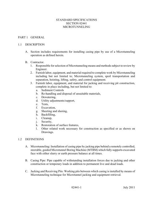
STANDARD SPECIFICATIONSSECTION <strong>02441</strong>MICROTUNNELINGPART 1 GENERAL1.1 DESCRIPTIONA. Section includes requirements for installing casing pipe by use of a <strong>Microtunneling</strong>operation as defined herein.B. Contractor.1. Responsible for selection of <strong>Microtunneling</strong> means and methods subject to review byEngineer.2. Furnish labor, equipment, and material required to complete work by <strong>Microtunneling</strong>including but not limited to; <strong>Microtunneling</strong> system, spoil transportation andseparation, hoisting, lifting, safety, and control equipment.3. Furnish labor, equipment, and material for jacking and receiving pit construction,complete in place including, but not limited to:a. Sediment Controlsb. Re-handling and disposal of unsuitable materials,c. Dewatering,d. Utility adjustments/support,e. Tests,f. Excavation,g. Sheeting and shoring,h. Backfilling,i. Cleanup,j. Security,k. Restoration of surface features,l. Other related work necessary for construction as specified or as shown onDrawings.1.2 DEFINITIONSA. <strong>Microtunneling</strong>: Installation of casing pipe by jacking pipe behind a remotely controlled,steerable, guided Microtunnel Boring Machine (MTBM) which fully supports excavatedface with either slurry or earth pressure balance at all times.B. Casing Pipe: Pipe capable of withstanding installation forces due to jacking and otherconstruction or temporary loads in addition to permanent live and dead loads.C. Jacking and Receiving Pits: Working pits between which casing is installed by means of<strong>Microtunneling</strong> technique for Microtunnel jacking and equipment retrieval.<strong>02441</strong>-1 July 2011
D. Drive: Section of casing pipe installed by <strong>Microtunneling</strong> from Jacking Pit to ReceivingPit.E. Slurry Pressure Balance System.1. <strong>Microtunneling</strong> system that mixes excavated material with slurry in a chamberlocated behind cutting head.2. Low pressure slurry is used to balance ground and water pressure at face of tunnel,limit settlement and convey cuttings back to ground surface.3. Cuttings are removed or separated and slurry is re-circulated back to MTBM.F. Earth Pressure Balance System.1. <strong>Microtunneling</strong> system which incorporates continuous flight auger enclosed inseparate casing inside casing pipe being jacked.2. Positive pressure is maintained at excavated face by regulating volume of cuttingsremoved relative to advance rate of MTBM.G. Spoil: Excavated material that has been mixed with either water or slurry and pumped tosurface to be separated and recycled or disposed.H. Tunnel: Microtunnel casing pipes complete in place.1.3 QUALITY ASSURANCEA. Supervision.1. <strong>Microtunneling</strong> and work associated with microtunneling:a. Supervised by at least 1 person with previous experience of microtunnelingprocess.b. See minimum requirements under Submittals herein.B. Operators.1. Personnel experienced in microtunneling with prior knowledge and ability in properoperation of systems being employed.2. See minimum requirements under Submittals herein.C. Operation.1. Operate systems following manufacturer's instructions.2. Make available at all times copies of operations manuals to Engineer and operationalpersonnel on site.D. Run Test: Test full system on completion of set up and before commencing drive.E. Drive Start Up.1. Before commencement of any drive, demonstrate to Engineer that required set upprocedures and system checks are complete and required materials are at hand tocommence drive.2. Do not commence drive until construction of Receiving Pit has been completed.<strong>02441</strong>-2 July 2011
1.4 SUBMITTALSA. Submit following Section 01330.1. If modifications are required during construction, submit to Engineer for approvalinformation illustrating such modifications, including reasons.2. <strong>Microtunneling</strong> Qualifications for Contractor Performing <strong>Microtunneling</strong> Work.a. Cover sheet with date, company name, address, telephone and fax numbers,email address, and contact person.b. Resumes of managerial, supervisory and operational key personnel:1) Experience: Minimum of 3 previous <strong>Microtunneling</strong> projects of similar sizeand scope.2) Detailed descriptions of <strong>Microtunneling</strong> Projects.c. Summary sheet of previous projects performed using <strong>Microtunneling</strong> thatdemonstrates expertise and experience. Named projects may be used more thanonce under separate paragraphs if their criteria apply.1) Minimum 3 years experience performing <strong>Microtunneling</strong> of similar size andscope.2) List 3 separate projects completed that used either Slurry or Earth PressureBalance based system.d. Submit for each named project above, and in same order, following detailedinformation.1) Date, full name of project, and location.2) Owner's name, address, telephone and fax numbers, email address, andcontact person.3) Client's name, address, telephone and fax numbers, email address, andcontact person.4) Employees in charge of work at both head office and site.5) Description of relevant work successfully completed, including groundconditions.6) Features under which pipe passed, depth below the water table, photos, andpublished articles if available.7) Additional information as necessary.e. Equipment.1) Supply full details of <strong>Microtunneling</strong> System to be employed.2) Manufacturer and date(s) of manufacture.3) Type and model number for whole system if from single source or separatedetails for each element of system.4) Confirmation from manufacturer that machine set up is suitable to limitannular space, as specified, for external diameter of casing pipe proposed.5) System of alignment monitoring and steering control and activation.6) Hydraulic jacking system maximum capacity and method of limitingjacking capacity to that of maximum capacity of specified casing.f. Procedures.1) Supply full details of procedures and resources that will be employed tocarry out work including method and sequence.<strong>02441</strong>-3 July 2011
a) Establishment of drive line of MTBM and elevation at base of shaft.b) Casing Pipe handling and connections.c) Maintaining line and grade, and reestablishment of line and grade asrequired.d) Spoil separation and disposal.e) Spoil and slurry containment during <strong>Microtunneling</strong> work.f) Installation of carrier pipe, including placement of grout betweencarrier pipe and casing pipe, and procedures to prevent floatationduring grouting.g. Materials.1) Supply full details of following materials.a) Design mixes for concrete, grout, or flowable fills.b) Casing pipe including manufacturer, grade, and specification, outsidediameter, thickness, and any coatings, if required.h. Calculations that clearly state:1) Maximum calculated jacking resistance for installing complete casing.2) Maximum allowable face pressure or slurry pressure that can be exerted attunnel face without fluid loss to surface, other structures or features orheave of ground.3) Relationship between hydraulic jacking pressure and force applied to casingpipe during jacking.3. Jacking and Receiving Pits.a. Submit station specific Working Drawings to include but not limited to:1) Jacking and receiving pit configurations.2) Design and construction of jacking and receiving pits.3) Details for ground support system.4) Special requirements for jacking and receiving pit penetrations, thrustblocks, backstops or other reactions required for <strong>Microtunneling</strong>, casingpipe jacking or any other jacking.5) Full calculations supporting maximum jacking capacity that jacking pit willwithstand without movement exceeding 0.5 inches with an appropriatefactor of safety.6) Areas for storage, material and spoil handling, dewatering, groundstabilization if required, excavation procedures, and backfilling followingSection 02315.7) Dewatering and ground water control plans for jacking and receiving pits.4. Settlement Monitoring Plan.a. Submit surveying and monitoring plan for review before construction. Identifylocation of settlement monitoring points, reference benchmarks, surveyschedules and procedures, and reporting formats.b. Submit Building and Structures Assessment Plan for review before construction.1) Furnish pre-construction and post-construction assessment for building andstructures located within distance of 100 feet from centerline of proposedtunnel, and jacking and receiving pits.2) Include photographs or video of existing damage to structures nearalignment.<strong>02441</strong>-4 July 2011
1.5 RECORD DRAWINGS (As-builts)A. Maintain at construction site complete set of field drawings for recording as-builtconditions.B. Mark or note thereon up-to-date as-built conditions properly dated.1.6 DELIVERY, STORAGE AND HANDLINGA. Unload and handle materials with equipment of adequate capacity, equipped with slingsto protect materials from damage.1. Store materials on site in reasonably level well-drained area free from brush.2. Store individual pieces and bundles with safe walking space between to allow fullview for inspection purposes.1.7 PROJECT CONDITIONSA. Perform <strong>Microtunneling</strong> so as not to interfere with, interrupt or endanger surface andactivity thereon, and minimize subsidence of surface, structures, and utilities above andnear tunnel.B. Repair and restore damaged property from tunnel operation settlement to its originalcondition before being disturbed at no cost to Commission.C. Review and interpret available geotechnical reports and investigate work site soilconditions before bidding.1. Encountering rock or water will not entitle Contractor to additional compensation.D. Follow applicable ordinances, codes, statutes, rules, and regulations of State of Maryland,MSHA, applicable County building codes, affected Railroad Company, and applicableregulations of Federal Government, OSHA 29CFR 1926, and applicable criteria of ANSIA10.16-1995 (R2001), “Safety Requirements for Tunnels, Shafts, and Caissons.”1.8 ADDITIONAL CRITERIA FOR WORK UNDER RAILROADSA. Do not schedule tunnel construction within and adjacent to Railroad property untilEngineer and Railroad approve submittals, including proper Railroad insurance.1. Approval does not relieve Contractor of responsibility for adequacy and safety ofprocedure.B. Give Railroad advance written notice as described in permit and copied to Engineerbefore entering and working on Railroad property.<strong>02441</strong>-5 July 2011
C. Place in effect, before work proceeds, all safety, precautionary and protective devices,and services required by Railroad.D. Follow AREMA or other applicable railroad specification and permit requirements.E. At railroad crossing, Contractor may be required, at his own expense, to submit anadditional permit pipeline crossing application for approval by railroad.PART 2 PRODUCTS2.1 MATERIALSA. Casing Pipe.1. Steel pipe.a. Smooth walled with minimum yield strength of 36,000 psi (ASTM A1011Grade 36).b. Minimum wall thickness 3/8 inch or as indicated on Drawings.c. Joints: Fully welded around circumference of pipe.1) Weld of sufficient strength to withstand forces at pipe joints without anydistortion of pipes.2) Minimum welds: Follow Standard Details.d. Coating: Nonee. Modifications to design of steel casing pipe for MTBM compatibility.1) Make request to Engineer.2. Other Pipes: Submit following Section 01630.B. Carrier Pipe.1. Meet requirements specified in Sections 02510, and 02530.C. Surface Settlement Markers.1. Within Bituminous Concrete Paved Areas: "p.k." nails.2. Within Nonpaved Areas: Wooden hubs.D. Subsurface Settlement Indicator: See Standard Detail M/7.0.E. Grout: Three parts sand, ASTM C144, to 1 part of cement, ASTM C150 to fill annularspace between casing pipe and carrier pipe.1. Cement: ASTM C150, Type II.2. Water: See Section 03300.3. Sand: ASTM C404, size No. 1.4. Design Mix For Grout: Minimum compressive strength of 100 psi attained within 24hours.F. Dielectric Material.1. Thermoplastic; Minimum strength of 400 volts for each mil, and water absorptionless than 0.02 percent (24-hour period).<strong>02441</strong>-6 July 2011
G. Equipment.1. <strong>Microtunneling</strong> System.a. Closed face capable of providing positive supporting pressure to full excavatedarea (face) at all times and capability of controlling and measuring pressure atface.b. Achieve balancing of earth and ground water pressures by use of slurry pressure,auger-earth pressure balance, or combination of the two.c. System capable of adjustments required to maintain face stability for anticipatedground conditions.d. Control slurry pressure systems, using slurry spoil transportation, earth andgroundwater pressure at face by use of variable flow slurry pumps, pressurecontrol valves and minimum of 2 flow meters, 1 on feed side and 1 on returnside.e. For earth pressure balance systems using screw auger spoil transportation fromthe face, control excavated material by maintaining an earth pressure balancingplug of material at face with advance of system being matched with excavationremoval through auger.1) Control soil through auger by use of pitch spacing and/or an auger gate orthrottle.f. Sufficient power and ability in normal operation to cut or crush hard material ofsizes up to 1/3 internal diameter of pipe and up to 30,000 psi compressivestrength.g. Ability to control axial rotation to within 3-degrees of normal operating datum.h. Ability to articulate and steer to correct vertical and horizontal deviation fromalignment datum by remote activation.i. Means to inject lubricant over lead pipe, if required.j. Spoil transportation system that has capacity for removal of spoil in balancewith excavation and advance.k. Slurry system.1) Spoil separation system with sufficient capacity to remove solids from flowwhile system is excavating spoil.2) Discharges safely with negligible remaining fines, the re-circulated orexcess fluid.l. Overall control system that enables remote control of all main operatingfunctions of system from one location, either at surface or within jacking shaft.m. Main jacking pit capable of exerting uniform load to casing pipe at speedcommensurate with speed of excavation advance.1) Set jacking hydraulics to relieve pressure at maximum safe workingcapacity of casing pipe.PART 3 EXECUTION3.1 GENERAL<strong>02441</strong>-7 July 2011
A. Dewatering: When water is encountered, develop and maintain dewatering system ofsufficient capacity to remove water continuously, keeping excavations free of water untilbackfill operation is in progress.1. Keep removal of soils particles to minimum.2. Dewater into sediment trap following Section 01570.3. Observe to detect settlement or displacement of surface facilities due todewatering.4. Should settlement or displacement be detected, notify Engineer immediately andact to maintain safe conditions and prevent damage.3.2 DAILY ACTIVITY LOGA. Maintain daily activity log during jacking operations for casing. Submit to Engineer forrecord purposes on a daily basis.1. Start and finish time of casing pipe advancement.2. Total length of casing pipe installed.3. Horizontal and vertical alignment deviation at not greater than 1 foot intervals orperiod not exceeding 5 minutes, whichever is most frequent.4. Maximum jacking force exerted during installation of each casing pipe sectionincluding forces required to re-initiate jacking following periods of system shutdown.5. General description for each discernible ground condition mined.6. Settlement monitoring readings.B. Where <strong>Microtunneling</strong> system utilizes an electronic data logger, set up so the aboveinformation is recorded and can be readily identified.1. Identify known errors with recorded data and explain in daily log submittal.3.3 PREPARATIONA. Maintain clean working conditions inside jacking operation area and remove spoil, debris,equipment, and other material not required for operations.B. For construction below railroads, highways and utilities perform installation to preventinterference or disruption with normal operation of these facilities.C. During construction, maintain access to private and commercial properties at all times,unless approval from both property owner and Engineer has been obtained.1. Costs associated with providing alternative access will be at no additional cost toCommission.D. Provide power generation equipment and other equipment operating on or with fuel orlubrication oils with suitable barriers and safeguards to ensure no loss of oil to drains orwaterways or to contaminate ground.3.4 JACKING AND RECEIVING PIT CONSTRUCTION<strong>02441</strong>-8 July 2011
A. Responsible for design, construction, maintenance and removal, including any damageattributed to jacking and receiving pit construction.B. Jacking and Receiving Pits: See Working Drawings.C. Excavation, Backfill, and Grading: See Section 02315.D. Approximate Locations of Jacking and Receiving Pits: See Drawings.E. Responsible for necessary utility relocation or supporting of utilities for jacking andreceiving pits construction.3.5 MICROTUNNELING OF CASING PIPEA. Tolerances.1. Place casing pipe to within 1 inch of vertical and horizontal alignment shown onDrawings.2. Limit annular space, between excavated material and outside diameter of casing pipe,to maximum of 0.5-inch.3. Outside diameter of MTBM not to exceed outside diameter of casing pipe by morethan 1 inch.4. Redesign of pipeline or associated structures if jacked casing pipe is off design lineor grade, will be at no additional cost to Commission.B. Obstructions during <strong>Microtunneling</strong>.1. Responsible for selection of type of MTBM and type of cutting.2. Remove, clear, or otherwise make it possible for <strong>Microtunneling</strong> system and casingpipe to progress past or through any obstructions encountered.3. Removing, clearing or otherwise making it possible for <strong>Microtunneling</strong> System toprogress past any obstructions encountered will be at no additional cost toCommission.3.6 INSTALLATION OF CARRIER PIPEA. Follow Sections 02315, 02510, and 02530, Standard Details, and Drawings.B. Use thermoplastic or other dielectric material (except wood) between carrier pipe andtunnel liner plate or steel sleeve to prevent metal-to-metal contact and damage to pipe andcoating during placement.C. Bulkhead: Follow Drawings.3.7 DETECTION OF MOVEMENT: See Section 02420.PART 4 MEASUREMENT AND PAYMENT<strong>02441</strong>-9 July 2011
4.1 MICROTUNNELING OF CASING PIPEA. Measurement: By linear foot of casing pipe installed in place as shown on Drawingsmeasured horizontally along the centerline of tunnel between interior face of the jackingpits to the interior face of receiving pits.B. Payment: At unit price per linear foot listed in Bid Schedule.1. Payment includes labor, materials, tools and equipment, excavation and backfilloutside the limits of the normal trench width, disposal of excess excavated material,receiving and jacking pits, casing pipe, necessary grouting, bulkheads at each end onthe casing pipe, subsurface settlement indicators, settlement markers, and other workinvolved in the <strong>Microtunneling</strong> of casing pipe following Contract Documents.2. Carrier pipe installed inside the casing pipe will be measured and paid for asdescribed elsewhere in specifications.**WSSC**<strong>02441</strong>-10 July 2011


