DDNG485-NA - Philips Lighting Controls
DDNG485-NA - Philips Lighting Controls
DDNG485-NA - Philips Lighting Controls

You also want an ePaper? Increase the reach of your titles
YUMPU automatically turns print PDFs into web optimized ePapers that Google loves.
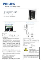
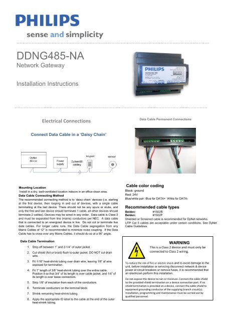
…………………………………………………....…………………………………………………………<strong>DDNG485</strong>-<strong>NA</strong>Network GatewayInstallation Instructions…………………………………………………....…………………………………………………………Electrical ConnectionsData Cable Permanent ConnectionsConnect Data Cable in a ‘Daisy Chain’Mounting LocationInstall in a dry, well-ventilated location indoors in an office-clean area.Data Cable Connecting MethodThe recommended connecting method is to ‘daisy chain’ devices (i.e. startingat the first device, then looping in and out of devices, with a single cableterminating at the last device. There should not be any spurs or stubs, andonly the first and last device should terminate 1 cable, all other devices shouldterminate 2 cables). Devices may be wired in any order. Data cable is Class 2and must be separated from line (mains) conductors per NEC. A data cablethat is connected to an energized device is live. Do not cut or terminate livedata cables. For longer cable runs, the Data Cable segregation from anyMains Cables of 12” is recommended to minimize noise coupling. If the DataCable has to cross over any Mains Cables, it should do so at a 90° angle.Data Cable Termination1. Strip off between 1” and 2-1/4” of outer jacket.2. Cut shield (foil or braid) flush to outer jacket. DO NOT cut drainwire.3. Fit 1/16” heat-shrink tubing over drain wire, leaving 1/8” of wireexposed for termination.4. Fit 1” length of 3/8” heat-shrink tubing over the entire cable.Position it so that 3/4” of its length is over cable jacket, and 1/4” ofits length is over loose connectors.5. Strip 1/8” of insulation from each of the conductors.6. Terminate conductors on the terminal block.7. Shrink remaining heat-shrink tubing.8. Apply the appropriate ID label to the cable at the end of the outerheat-shrink tubing.Cable color codingBlack: groundRed: 24VBlue/white pair: Blue for DATA+ White for DATA-Recommended cable typesBelden: #1502RBelden: #1502PShielded or Screened cable is recommended for DyNet networks.UTP Cat 5 cables are acceptable under certain conditions. See DyNetCable Guidelines.WARNINGThis is a Class 2 device and must only beconnected to Class 2 wiring.To reduce the risk of fire or electric shock and to avoid damage to theunit, before installation or servicing disconnect network & devicepower at circuit breakers or remove fuses. It is recommended thatan electrician perform this installation.Do not expose this device to rain or moisture. Connect the cable shieldto the provided shield termination on a device connection port. If noshield termination is provided on a device, connect the cable shield toequipment grounding conductor of the supplying branch circuit(s).Installation, programming and maintenance must be carried out byqualified personnel.
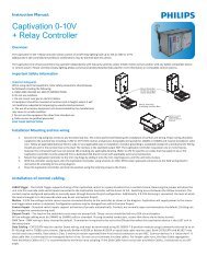
…………………………………………………....…………………………………………………………Installation steps1. Mount the device on a DIN rail inside an appropriate enclosure. Alternatively, make use of 3 internal holesprovided to fix the device to a surface without the use of DIN rail. Pull back the DIN rail clip detail to reveal themounting holes.2. Connect data cables to the device as per diagrams. Note that the device is powered from the DyNet networksegment that is connected to Port 1. When implementing Repeaters, connect the link to Port 2 of bothGateways. Shielded cable must be used for long runs. When implementing Trunk / Spur topology, connect theTrunk to Port 2 and the Spur to Port 1. Note that up to 330mA from the DyNet network on Port 1 is fed to Port 2,so providing there is surplus power available on the Spurs it is normally not necessary to provide a networkpower supply for the Trunk.3. If using the device as a DMX receiver, ensure DMX termination rules are obeyed. Fit a 120 Ohm terminatingresistor (minimum 1/2W rated) across D+ and D- at the end of line. Note that Port 2 should be used for DMXReception.…………………………………………………....…………………………………………………………Mounting dimensionsElectrical diagramThis device complies with Part 15 of the FCC Rules. Operation issubject to the following two conditions:(1) This device may not cause harmful interferenceand(2) This device must accept any interference received,including interference that may cause undesired operationThis Class A digital apparatus complies with Canadian ICES-003…………………………………………………....…………………………………………………………Product specificationsDyNet DC LoadMax. 330mA @ 24VDC, fed via Port 1.Max. load on Port 2 24VDC out: 150mAControl Ports 2 x RS485 DyNet serial portsSerial Port Isolation 2.5KV surge rated optical isolation betweenportsUser <strong>Controls</strong>Service switchDiagnostic LEDDMX512 FunctionsDMX512 receive: 64 data slotsDMX512 transmit: 64 data slotsDiagnostic Functions*Device Online/Offline status* MapView, Touch Screen or BAS interface required foranalyzing diagnostic data.TerminalsPort 1 (Input):6-way fixed screw terminal1 x 14 AWG or 2 x 18 AWG max conductor sizePort 2 (Output):5-way fixed screw terminal1 x 14 AWG or 2 x 18 AWG max conductor size1 x RJ45 jack for plug in service connectionCompliance FCC, RoHS, ICES Compliant (see statements)Operating Environment32º to 122ºF (0º to 50ºC) ambient temp0% to 90% RH non- condensingConstruction Polycarbonate DIN Rail case (6 units wide)Dimensions H 3.7” x W 4.1” x D 3.0”Weight Packed weight 0.55 lb…………………………………………………....…………………………………………………………<strong>DDNG485</strong>-<strong>NA</strong> Installation Instructions Rev B.Sep 24, 2010 Specifications subject to change without notice. All rights reserved.Dynalite, DyNet and associated logos are the registered trademarks of <strong>Philips</strong> Dynalite. Not to be reproduced without permission.Manufactured by WMGD Pty Ltd (ABN 33 097 246 921) Unit 6, 691 Gardeners Road, Mascot, NSW 2020, AustraliaWeb: lightolier.com E-Mail: controls.support@philips.com. Tel: 1-800-526-2731