

MODEL ER-A320 SERVICE MANUAL - diagramas.diagram...
MODEL ER-A320 SERVICE MANUAL - diagramas.diagram...
MODEL ER-A320 SERVICE MANUAL - diagramas.diagram...
- No tags were found...

You also want an ePaper? Increase the reach of your titles
YUMPU automatically turns print PDFs into web optimized ePapers that Google loves.
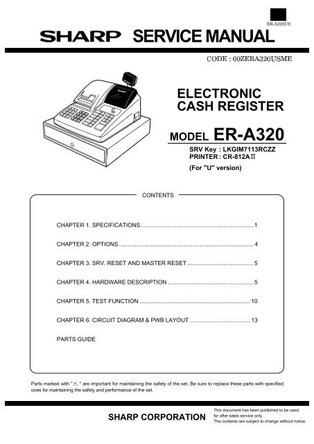
S<strong>ER</strong>VICE <strong>MANUAL</strong>ELECTRONICCASH REGIST<strong>ER</strong><strong>MODEL</strong> <strong>ER</strong>-<strong>A320</strong>SRV Key : LKGIM7113RCZZPRINT<strong>ER</strong> : CR-812A(For "U" version)CONTENTSCHAPT<strong>ER</strong> 1. SPECIFICATIONS ....................................................................... 1CHAPT<strong>ER</strong> 2. OPTIONS ..................................................................................... 4CHAPT<strong>ER</strong> 3. SRV. RESET AND MAST<strong>ER</strong> RESET.......................................... 5CHAPT<strong>ER</strong> 4. HARDWARE DESCRIPTION ...................................................... 5CHAPT<strong>ER</strong> 5. TEST FUNCTION ...................................................................... 10CHAPT<strong>ER</strong> 6. CIRCUIT DIAGRAM & PWB LAYOUT ...................................... 13PARTS GUIDEParts marked with " " are important for maintaining the safety of the set. Be sure to replace these parts with specifiedones for maintaining the safety and performance of the set.SHARP CORPORATIONThis document has been published to be usedfor after sales service only.The contents are subject to change without notice.
CHAPT<strong>ER</strong> 1 . SPECIFICATIONS1. Appearance/Rating1) AppearanceJournal paperPrinter coverReceipt paperCustomer display (Pop-up type)Operator displayMode switchKeyboardDrawerDrawer lock2) RatingPower sourcePower consumptionOperating temperatureOperating humidityPhysical dimensionsincluding the drawerWeight2. Keyboard120V AC m 10%, 60 HzStand-by: 9WOperating: 35W (Max.)32°F to 104°F (0°C to 40°C)10% to 90% (RH)420 (W) x 423 (D) x 304 (H) mm(16.5 (W) x 16.7 (D) x 12.0 (H) in.)13.0 kg (28.7 lbs.)1) Standard keyboard layoutCLReceipt Journal C@RCPT PRINTFORRARMPOCAL%RFNDVOID7418529630 00 •PLU/SUBX-+5 104321NS9876TAX1SHIFT AUTOCHCONVMDSESBTL CHK#/TM/SBTL=CA/AT2) Key top nameStandard key topKEY TOPRECEIPTJOURNALDESCRIPTIONReceipt paper feed keyJournal paper feed key0~9, 00 Numeric keys. Decimal point key@/FOR Multiplication keyCL/CClear keyPRINT Validation print keyDept.1/+ Department 1/Plus key (Calc. mode)Dept.2/– Department 2/Minus key (Calc. mode)Dept.3/u Department 3/Multiplication key (Calc. mode)Dept.4/v Department 4/Division key (Calc. mode)Dept.5~10 Department 5~10 keysPLU/SUB PLU/Subdepartment keyRCPT Receipt print key- Discount keyAUTO Automatic sequencing key% Percent keyNSNo-sale key
KEY TOPRA/RMPO/CALRFNDVOIDCHCHKCONVMDSE SBTL#/TM/SBTLCA/AT/=TAX1 SHIFTDESCRIPTIONReceived on account/Recall memory key (Calc. mode)Paid out/Calculation mode keyRefund keyVoid keyCharge keyCheck keyConversion keyMerchandise subtotal keyNon-add code/Time display/Subtotal keyCash/Amount tendered/Equals key (Calc. mode)TAX1 shift keyDISPLAY DEVICELEDNUMB<strong>ER</strong> OF LINE1 lineNUMB<strong>ER</strong> OF POSITIONS 10 positionsCOLOR OF DISPLAYGreenCHARACT<strong>ER</strong> SIZE14.2mm (H) x 8.0mm (H)2) Customer display (Pop-up type)Optional key topKEY TOPDept. 11~40DEPT#TAX2 SHIFT~TAX4SHIFTAUTO2CONV2~4CA2DESCRIPTIONDepartment 11~40 keysDepartment number entry keyTax2~Tax4 shift keysAutomatic sequencing 2 keyConversion 2~4 keysCash total 2 keyCH2Charge 2 key- 2 Discount 2 key%2 Percent 2 keyDISPLAY DEVICELEDNUMB<strong>ER</strong> OF LINE1 lineNUMB<strong>ER</strong> OF POSITIONS 7 positionsCOLOR OF DISPLAYGreenCHARACT<strong>ER</strong> SIZE14.2mm (H) x 8.0mm (H)3) LampsDESCRIPTIONAMOUNT 1~8MINUS SIGN 2~10 : Floating<strong>ER</strong>ROR 10PGM MODE 103. Display1) Operator displayPLU/SUBDEPTRCPTOFFREPEAT: This appears when a transaction is finalized.: This appears when the cash register computes the subtotal.: This appears when the change due amount is displayed.CA/ATCHCHKSUBTOTAL/SHORT TEND<strong>ER</strong>10 : Lights up when a registrationis finalized by depressingCA/AT, CH or CHK key10CHANGE 10 : Lights up whenever thechange due amount appearsin the display.DEPARTMENT 9~10 No zero-suppressed.PLU 8~10 No zero-suppressed.REPEAT 8 Endless count, starting from 2.DECIMAL POINT 5~1 TAB (4~2)RECEIPT OFF 9 —VALIDATION 10 : Light up when the validationprinting is compulsory.CONV<strong>ER</strong>SION orCALC. MODE10: This appears when for the calculator mode.
4. Printer1) Printer specificationsITEMSModel nameNo. of stationPrintingsystemPrintingcapacityCharactersizePrint pitchPrint speedPaper feedspeedReliabilityValidationform sensorNear endsensorCutterPrint wheellayoutCR-812A2 (Receipt/Journal)Print wheel selective typeReceipt : Max. 10 chr.Journal : Max. 10 chr.Validation : Max. 20 chr./1 lineFigure: 1.7mm (W) x 3.2mm (H)Symbol : 2.4mm (W) x 3.2mm (H)Column distance : 3.35mm for between 1st and 2ndcolumn 3.0mm for after 3rd columnRow distance : 5.1mmApprox. 2.5 lines/sec.Approx. 17 lines/sec. at receipt issued.MCBF 2.5 million linesNoJournal side: NoReceipt side: NoManualParts code: 00BM73100230010 9 8 7 6 5 4 3 2 1PL Z TX . . . . GT CA @- - - - - - - # CK Q% CH CG2) Roll paperParts codeDimensionPaper quality3) Validation paperPaper qualityPrinting area4) InkingParts codeInk supply systemFormSpecificationRoller lifePrint colorDPAPR1006CSZZ44.5m 0.5mm in widthMax. 80mm in diameterJournal/ReceiptFine quality paperPaper thickness : 0.06 to 0.09 mmPaper weight : 52.3 to 64g/m 2Validation formNormal paper onlyThickness : 0.08 to 0.19 mmSize : 115mm or more, 210mm orunder (W) x 70mm or more (H)Normal paper and pressure sensitive paper onlyThickness : 0.07 to 0.14 mmSize : 115 mm or more (W) x 70 mm or more (H)29.4 19.1 29.410Dig.Wide over 115mmNROLR6638RCZZInk rollerRollerMaterial-rubberApprox. 0.6 million linesPurple10Dig.1616.60101010101010101RAPOTD15) Logo stamp2345623456234562345623456234562345623456VDNSTXFS23456MaterialSizeColorParts code for inkPorous rubber30mm (W) x 20mm (H)PurpleUINK1001CCZZ77777777X½8989898989898989EXRFSTTL5. Drawer1) Drawer box and drawerModel name SK423Size420(W) x 423(D) x 112(H) mmColor Gray 368MaterialMetalBell —Release lever Standard equipment; Situated at the bottomDrawer open sensor Standard equipment
2) Money case3) LockSeparation from the drawerAllowedLocation of the lockFrontSeparation of the coin compartments from themoney caseDisallowedBill separator —Number of compartments5B/5CBill compartmentsMethod of lockingand unlockingKey No.Locking :Unlocking :SK1-1lnsert the drawer lock key into thelock and turn it 90 degreescounterclockwise.lnsert the drawer lock key into thelock and turn it 90 degreesclockwise.Coin compartments5B/5CCHAPT<strong>ER</strong> 2. OPTIONS1. Sales optionsNo. NAME <strong>MODEL</strong> DESCRIPTIONS1 COIN CASE <strong>ER</strong>-55CC2 5B/5C (For "U" version)2 KEY TOP KIT <strong>ER</strong>-11KT7 1 x 1 key top<strong>ER</strong>-12KT7<strong>ER</strong>-22KT7<strong>ER</strong>-11DK7G<strong>ER</strong>-51DK7G1 x 2 key top2 x 2 key top1 x 1 dummy key5 x 1 dummy key2. Service optionsNo. NAME PARTS CODE PRICE RANK DESCRIPTIONS1 SRV KEY AK2 MODE KEYGRIP COV<strong>ER</strong> AL OP key only3 DRIP-PROOF KEYBOARD COV<strong>ER</strong> BE3. SuppliesNo. NAME PARTS CODE PRICE RANK DESCRIPTIONS1 ROLL PAP<strong>ER</strong> AR2 INK ROLL<strong>ER</strong> AY3 INK FOR STAMP AK
CHAPT<strong>ER</strong> 3. SRV RESET AND MAST<strong>ER</strong> RESETThe SRV key is used for operating in the SRV mode.1. SRV reset (Program Loop Reset)Used to return the machine back to its operational state after a lockuphas occurred.Procedure· Method 11) Unplug the AC cord from the wall outlet.2) Set the mode switch to (SRV’) position.3) Plug in the AC cord to the wall outlet.4) Turn to (SRV) position from (SRV’) position.· Method 21) Set the mode switch to PGM position.2) Unplug the AC cord from the wall outlet.3) While holding down JOURNAL FEED key and RECEIPT FEEDkey, plug in the AC cord from the wall outlet.Note: 1. The <strong>ER</strong>-<strong>A320</strong> printer will cycle and print the following on thejournal2. Master reset (All memory clear)Used to clear all memory contents and return machine back to initialsettings.(Returns keyboard back to the default keyboard layout.)Procedure1) Unplug the AC cord from the wall outlet.2) Set the MODE switch to the (SRV’) position.3) Plug in the AC cord to the wall outlet.4) While holding down JOURNAL FEED key, turn from (SRV’) positionto the (SRV) position.Note: 1. The <strong>ER</strong>-<strong>A320</strong> display will flash the "." decimal point at theright most position and will beep 3 times.2. The <strong>ER</strong>-<strong>A320</strong> printer will cycle and print the following on thejournal12CHAPT<strong>ER</strong> 4. HARDWARE DESCRIPTION1. Block <strong>diagram</strong>PRINT<strong>ER</strong> POW<strong>ER</strong> SOURCE : +18VTRANSFORM<strong>ER</strong>VOLTAG<strong>ER</strong>EGULATORDRIVE SIGNALDISPLAY POW<strong>ER</strong> SOURCE : +5.5VDRIV<strong>ER</strong>DRAW<strong>ER</strong>NI-MH BATT<strong>ER</strong>YDC-DCCONV<strong>ER</strong>T<strong>ER</strong>DRIVE SIGNALTIMING SIGNALDRIV<strong>ER</strong>BUZZ<strong>ER</strong>MOTORDRIV<strong>ER</strong>STROBESIGNALDRIVE SIGNALKEYBOARD8X9 72KEYCPUµPD78045DRIVE SIGNALHAMM<strong>ER</strong> COMMON SIGNALSTAMP, PAP<strong>ER</strong>FEED DRIV<strong>ER</strong>PRINT<strong>ER</strong>CR-812AMODESWITCH8SIGNALRETURNSIGNALLATCHSIGNALADDRESSLATCHDRIVE SIGNALPRINT WHEELMG DRIV<strong>ER</strong>CHIP SELECTSIGNALADDRESSBUSADDRESSBUSS-RAM256 kbitDATA BUSSEGMENTDRIV<strong>ER</strong>DIGIT DRIV<strong>ER</strong>OP.DISPLAY7SEG LED10DIGPOP-UPDISPLAY7SEG LED7DIGDIGIT SIGNAL
2. CPU (UPD78045F) pin configurationNo.PINNAMESIGNALNAMEDESCRIPTION1 P94 DIG7 Display digit 7 O H2 P93 DIG6 Dlsplay digit 6 O H3 P92 DIG5 Display digit 5 O H4 P91 DIG4 Display digit 4 O H5 P90 DIG3 Display digit 3 O H6 P81 DIG2 Display digit 2 O H7 P80 DIG1 Display digit 1 O H8 VDD VDD +5V9 P27 AD7 RAM Address & Data bus 7Printer magnet 8I/O H10 P26 AD6 RAM Address & Data bus 6Printer magnet 711 P25 AD5 RAM Address & Data bus 5Printer magnet 612 P24 AD4 RAM Address & Data bus 4Printer magnet 513 P23 AD3 RAM Address & Data bus 3Printer magnet 414 P22 AD2 RAM Address & Data bus 2Printer magnet 315 P21 AD1 RAM Address & Data bus 1Printer magnet 216 P20 AD0 RAM Address & Data bus 0Printer magnet 117 /RESET /RESET Reset signal I L18 P74 NU NU O H19 P73 NU NU O H20 AVSS AVSS GND21 P17 KR11 Key return signal 11 I H22 P16 KR10 Key return signal 10 I H23 P15 KR9 Key return signal 9 I H24 P14 KR8 Key return signal 8 I H25 P13 KR7 Key return signal 7 I H26 P12 KR6 Key return signal 6 I H27 P11 KR5 Key return signal 5 I H28 P10 VB Battery voltage I29 AVDD AVDD +5V30 AVREF AVREF +5V (VCC)31 XT1 P04 Sub clock: 32.768 kHz I32 XT2 XT2 O33 VSS VSS GND34 X1 X1 Main clock: 4.19 MHz I35 X2 X2 O36 P37 MD Printer motor ON signal O H37 P36 BUZ Buzzer ON signal O H/L38 P35 RF Receipt paper feed signal O H39 P34 JF Journal paper feed signal O H40 P33 STAMP Stamp ON signal O H41 P32 /ALE Address latch signal O42 P31 /CE Chip select signal O LI/OI/OI/OI/OI/OI/OI/OI/OHHHHHHHNo.PINNAMESIGNALNAMEDESCRIPTION43 P30 /WE Write signal O L44 P03 RMS NU I45 P02 JMS Drawer open sensor I46 P01 a Printer timing signal I H47 P00 PE Power enable signal I H48 IC IC VSS49 P72 P72 NU O H50 P71 MG10 Printer magnet 10 O H51 P70 MG9 Printer magnet 9 O H52 VDD VDD +5V53 P127 R-COM Printer receipt commonsignalO H54 P126 J-COM Printer journal commonsignal55 P125 VDD Mode signal (VDD) I H56 P124 DR1 Standard drawer drive signal O H57 P123 KR4 Key return signal 4 I H58 P122 KR3 Key return signal 3 I H59 P121 KR2 Key return signal 2 I H60 P120 KR1 Key return signal 1 I H61 P117 A14 RAM Address 14 O62 P116 A13 RAM Address 13 O63 P115 A12 RAM Address 12 O64 P114 A11 RAM Address 11 O65 P113 A10 RAM Address 10 O66 P112 A9 RAM Address 9 O67 P111 A8 RAM Address 8 O68 P110 DR2 Option drawer drive signal O H69 P107 DP/ST8 Display segment signal DPKey strobe signal 8O H70 P106 G/ST7 Display segment signal GKey strobe signal 771 VLOAD VLOAD GND72 P105 F/ST6 Display segment signal FKey strobe signal 673 P104 E/ST5 Display segment signal EKey strobe signal 574 P103 D/ST4 Display segment signal DKey strobe signal 475 P102 C/ST3 Display segment signal CKey strobe signal 376 P101 B/ST2 Display segment signal BKey strobe signal 277 P100 A/ST1 Display segment signal AKey strobe signal 178 P97 DIG10 Display digit signal 10 O H79 P96 DIG9 Display digit signal 9 O H80 P95 DIG8 Display digit signal 8 O HI/OOOOOOOOOHHHHHHHH
3. RAM control/CE/WEA8~A14(WRITE)As shown in the attached time chart, address signals are output fromP20-P27, P111-P117, and the lower address is latched with P32. Thewrite enable signal (P30) is output. The write data to the RAM areoutput from P20-P27. Then the chip enable signal (P31) is output towrite the data.IC2CPU/ALEAD0~AD7IC374HC373A0~A7IC14S-RAMRAM control(READ cycle)P111~P117Upper addressAD0~AD7P20~P27Lower addressRAM data outputP32Lower addresslatch signal15ns or above15ns orabove70ns or above0ns or above/WE:Write signalWhen the signal is low, writing is performed. When the signalis high, reading is performed.P3030ns or aboveRAM /WE Fixed to HIGH./CE:A8-A14:Chip select signalAddress busRAM /OEFixed to LOWAD0-7:Address/Data busP31RAM /CSA0-1:Address bus signal/ALE: Address latch signalAddress signals A0-A7 are used commonly with the data bus. Whenthe address latch signal /ALE is input to IC3, the address/data bussignal AD0-AD7 access the RAM as address signals A0-A7.P20~P27 READ timingInputP20~P27 SelectOutput70ns or above(READ)As shown in the attached time chart, address signals are outputtedfrom P20-P27, P111-P117, and the lower address is latched with P32.The modes at P20-P27 are changed to the input mode. The chipenable signal (P31) is output for the RAM. Then the output data fromthe RAM are read from P20-P27.RAM controlHammer common5. Printer motor drive circuit1) Printer motor drive and brake circuit(WRITE cycle)P111~P117Upper addressVP : +18VQ17B1340VMP20~P27P32Lower addresslatch signal30ns or aboveLower address15ns or above15ns oraboveInput data to RAM30ns or above0ns or aboveMDIC6BKID65003PR78470R792.7KR8022KR812.7KQ18B926MP30RAM /WEIC2CPU50ns or aboveC32220PRAM /OEFixed to LOW.P20~P27RAM /CSP20~P27READ timing0ns orabove60ns oraboveP20~P27 SelectRAM Data INInputOutputThe printer motor is operated by switching operation of transistor Q17with the motor drive signal MD from the CPU.Hammer common
2) Print solenoid drive circuit4) Timing signal circuitVP : +18VQ19B926VJJ-COMC40100µF/16V+IC6DKID65003PR822.7KR83220/2WD281N4002VCC:+5VC2910U/16VIC2CPUR1361KAD0AD1AD2AD3AD4AD5AD6AD7MG9MG10AD0AD1AD2AD3AD4AD5AD6AD7MG9MG10IC7CIC7EIC7GIC8BIC8DIC8FIC9AIC9CIC9EIC9GD30RB441QIC7BIC7DIC7FIC8AIC8CIC8EIC8GIC9BIC9DIC9FJM1JM2JM3JM4JM5JM6JM7JM8JM9JM10RM1RM2RM3RM4RM5RM6RM7RM8RM9RM10IC2CPUαC371000P50VR1331KThe timing signal a is delivered to the CPU by the photo transistorattached to the printer.R-COMVP : +24VC41100µF/16V+IC6CKID65003PR842.7KQ20B926D291N4002R85220/2WVR5. Drawer drive circuitR1371KD31RB441QVP : +18VQ21C3784DR1R531KSTANDARD DRAW<strong>ER</strong>Since the address bus is used to drive the print solenoid, an access tothe RAM cannot be performed during printing. The common voltage ofthe print solenoid is supplied by switching operations of transistorsQ20 and Q19 with the J-COM signal and the R-COM signal.R5415KL23) Paper feed solenoid and stamp solenoid drivecircuitJMSR5515KIC2CPUR574.7KVMIC2CPURFJF176G7ADR2R891KVP : +18VQ14C3784OPTION DRAW<strong>ER</strong>STAMP16FRF:JF:STAMP:Paper feed solenoid drive signal (Receipt side)Paper feed solenoid drive signal (Journal side)Stamp solenoid drive signal (Receipt side)The solenoid is driven by switching operation of transistor Q21 with thedrive signal DR1 from the CPU.When an option drawer is used, the parts enclosed with the dotted linemust be attached to the PWB.
6. Keyboard circuit7. Display circuit+6V/RESETKR10C11M104D171SS133MODE SWITCHST1~ST8R4056KDIG1-DIG10DIG1'-7'DIG10'DIG9'DIG2'DIG1'ST8ST7D9D10IC2CPUPOP UPDISPLAYST6ST5ST4ST3D11D12D13D14KEY MATRIXFND5A',B',C',D',E',F',G',DP'FND4,3,2FND1A',B',C',D',E',F',G',DP'IC2CPUST2ST1D15D16Operator DisplayDP' G' F' E' D' C' B' A'DP~AKR1KR2RA256K X 8A,B,C,D,E,F,G,DPKR3KR4The 7-segment LED is used in the display. The operator display uses10 digit signals, and the pop-up display uses 7 digit signals.KR5KR68. Power supply circuitKR7POW<strong>ER</strong>TRANSFORM<strong>ER</strong>F1T1AL/250VREGULATORCIRCUITVP:+18V: PRINT<strong>ER</strong>, DRAW<strong>ER</strong>KR8+6v: DISPLAYKR9P-OFFCIRCUITP<strong>ER</strong>EGULATORCIRCUITVCC:+5VVDD:+5VR10256KBATT<strong>ER</strong>YCIRCUITVB: CPU,RAMThe keyboard performs key scanning with the eight strobe signalsST1-ST8, and returns a signal on KR1-KR9 to the CPU.The mode switch performs scanning with the eight strobe signals ST1-ST8, and returns the return signal KR10 to the CPU. When the modeswitch is at SRV position, the reset signal /RESET is outputted.9. Clock generator circuitP04C1622PX132.768KHzXT2IC2CPUR51330KC1433PX2R931MX24.19MHzX1X2: 4.19MHz is inputted as the CPU main clock.X1: 32.768KHz is inputted as the time renewal clock.
10. Buzzer circuitCHAPT<strong>ER</strong> 5. TEST FUNCTIONVDDR58IC2CPU/RESETC1910U/50V+1KQ16C3198R591KC1822U/16V+D241SS133VCC1. Start of test functionThe following key operation is required in the SRV mode to start thetest.XXXX ST/RESETC110.1µMODE SWITCHTest commandMaster reset is required when the system is to be started for the firsttime.This circuit sounds buzzer with the BUZ signal from the CPU.2. List of test commands11. Reset circuitNo. Test contents Key operations1 Mode switch test 1 ST2 Keyboard test XXXX02 STIC2CPU/RESETC1910U/50V+Q16C3198R581KVDDR591KC1822U/16V+D241SS133VCC3 Display and Buzzer test 3 ST4 Standard Drawer test 4 ST5 Option Drawer test 14 ST6 Printer test 5 ST7 RAM test 6 STNOTE-1: Test message is printed on the journalNOTE-2: The contents of the totalizer and the preset values are noterased by the test./RESETMODE SWITCH3. Test functionC11M1041) Test No. 1: Mode switch testKey operation1 STThe reset signal is formed with VCC and VDD. The /RESET signal isalso outputted when the mode switch is at SRV position.Then, turn the mode switches in the following order.In the mode switch test, turn the switch rhythmically.MODE: SRV PGM VOID OFF OP X/Z REGMGR X1/Z1 X2/Z2 SRVDISPLAY: (1) (2) OFF (3) (4)(5) (6) (7) (0)DescriptionAs the mode switch position number is displayed, check the number.TerminationThe test can be terminated when the mode switch is turned to theSRV side from other position.Termination print at normal endTermination print and error
2) Test No. 2: Keyboard testKey operationX X X X 02 STSum check dataTest command(1) Enter the test command in succession to the sum check dataof the model.NOTE:Model nameSum check data(Standard keyboard data)<strong>ER</strong>-<strong>A320</strong> 2518Sum check dataThe check sum is a decimal number obtained byconverting the hard code hexadecimal total of allkeys.The CA/AT key are the exception.(2) Next, push every key on the keyboard except for the receiptand journal keys.When the CA/AT key is pressed, the termination printout isimmediately produced assuming that all keys have beenpressed.There is no order in which the keys have to be depressed.Display: 02 XX XX=position code.[Keyboard position code of model vs. key to be pressed][All key position code]65 68 67 58 77 783) Test No.3: Display and buzzer testKey operation3 STDescriptionContinuous beeps and the display are tested.1. 2. 3. 4. 5. 6. 7. 8. 9. 0.The decimal point is shifted digit by digit from the lowest digit(every 200 msec).Then all segments are lighted (for about 1 sec).8. 8. 8. 8. 8. 8. 8. 8. 8. 8.Pressing any key will terminate the test.Check itemsCheck that each position display is correct.Check that the display is even and uniform.Check that the buzzer sound is normal. (No interruption and vibrationsof sounds.)Test endEnd printState of displayState of displayR7010J412161312064 6344 3424 745443235333736252226642327255457615563575055746361648472817383727184) Test No. 4: Drawer open testKey operation4 ST : For standard drawerDescription001101 14 04 13 0312022625060708With this test, the drawer opens and its state is displayed in thefollowing manner:[<strong>ER</strong>-<strong>A320</strong> standard keyboard layout]Drawer open XX 0Drawer closed XX CXX=04R7010J412161312063347454432353337368554576156756357505585746361677484778383727When the model that has no drawer sensor switch, displayed is"C".TerminationWith depression of any keyTermination print04 (For standard drawer)001101 04130326250608DescriptionUntil the depression of the ST key, the sum of key position codesis compared with the sum check data, except for the CA/AT key.TerminationThe test terminates with the depression of the CA/AT key andthe termination printout is produced.Termination print at normal endTermination print at error
DCBA18765432CHAPT<strong>ER</strong> 6. CIRCUIT DIAGRAM & PWB LAYOUT1. POW<strong>ER</strong>HEAT SINKUL CSA 2.0A/125VQ1F12SC4153VPUL CSA 4.0A/125VF2Q15BD12SB1243CN1C1M 0.033uPS CNDI102R23.9KQ42C4KTC1027330u50vR16800uF12K ZD1C250VMTZ20D+6VD6 1N4002CN14/CN14-1GNDVCCR3ZD2VCCMTZJ18B56KD3R5PE100K1SS133C5R4C363.3u2.7K3300P50V C6C 0.1u50VDIG1~10FM CNIC1Q2L1KTD1414220uHR7R63.6KF101 2KA34063AD4PS102RR8C71KF220PD7 1SS133VDDR138120ZD5R9MTZ6.2BC8C10100 C91000u330u330u16V16V16VBTGND+6VVBR101 1MR121R122 R123 R124 R125R126 R127 R128 R129 R130C34ST1~ST8CN212K0.1u/50VQ31Q32 Q33 Q34 Q35Q36 Q37 Q38 Q39 Q40 R121~R130: 12KQ31~Q33: A1271BT CNR111220R112 R113 R114 R115R116 R117 R118 R119 R120R111~R120: 220Q3Q4 Q5 Q6 Q7Q8 Q9 Q10 Q11 Q12Q3~Q12:C3198CN5R11R11,13,15,17,19,21,ST8 D9D102.2K R13 R15 R17 R19R21 R23 R25 R27 R2923,25,27,29 : 2.2KST7 ST6 D11Q34~Q40: B926ST5 D12ST4 D13ST3 D14DIG10' DIG9' DIG8' DIG7' DIG6'DIG5' DIG4' DIG3' DIG2' DIG1'ST2 D15D16FND5 FND4 FND3FND2 FND1ST1 CN151SS133*8CN8PPOP UP LED CN * 1KEY72PM CNCN8CN7GNDR37R36R35R34R33R32R31R30/RESET3030303030303030C11C 0.1u50VMAIN LED PWBDP'G'F'E'D'C'B'A'R132D17SEGA~DPC3198Q13R38R392.2k12k1SS133RA212KCA156KX8R402200PKR1056KKR1~KR9C332200PGFEDCBAST1~ST8IC5DP8 7 6 5 4 3 2 1KID65003PCN9PR10256KDCBA510751165125342513415143515251616453
DCBA187654323. POP-UP DISPLAYDIG7'DIG6'DIG5'DIG4'DIG3'DIG2'DIG1'FND4FND3 FND2 FND1CN1POP UP LED CN * 1PM CNR1027R1227R1427R1627R1827R2027R2227R2427DP'G'F'E'D'C'B'A'8 7 6 5 4 3 2 1DCBA
4. PWB LAYOTMAIN PWB LAYOUTPOP-UP PWB LAYOUT
PARTS GUIDE<strong>ER</strong>-<strong>A320</strong>U/A<strong>MODEL</strong> <strong>ER</strong>-<strong>A320</strong>SRV key : LKGiM7113RCZZPRINT<strong>ER</strong> : CR-812AIICONTENTS(For "U" & "A" Version)1 Exteriors2 Keyboard unit3 Packing material & Accessories4 Drawer box unit(SK-423type)5 Main PWB unit6 Pop up PWB unit7 Articles for consumption8 Service route options■IndexBecause parts marked with "!" are indispensable for the machine safety maintenance and poeration, itmust be replaced with the parts specific to the product specification.SHARP CORPORATIONThis document has been published to beused for after sales service only.The contents are subject to change withoutnotice.
<strong>ER</strong>-<strong>A320</strong>U/A1 ExteriorsPRICE NEW PARTNO. PARTS CODE RANK MARK RANKDESCRIPTION1 GCOVA7128BHSA AZ N D Printer cover2 PCUT-6654BHZZ AE C Paper cutter3 LX-BZ6788BHZZ AD C Screw4 GCOVH7124BHSD AF N D Battery cover5 PFILW6962BHZZ AU D Display filter6 GCABB7861BHZZ AN D Pop up cabinet7 CPWBF7504BH01 BC E Pop up LED PWB unit(NORMAL)8 QCNW-7815BHZZ AR C P-Flat cable (15p)9 PFILW6961BHZZ AP D Pop up filter10 XHPSD30P06K00 AA C Screw (M3´6K)11 XBBSC30P08000 AA C Screw (3´8)12 HDECP2368BHZZ AN N D Deco panelTCAUZ6684BHZA AE D Caution label [U.S.A]13TCAUZ6685BHZB AF D Caution label [Canada]14 GCABB7236BHZF BE N D Top cabinet15 GFTAF6921BHSC AH D Clerk cover A16 XEBSD30P08000 AA C Screw (3´8)17 QCNW-7805BHZZ AF C GND wire (PWB-K/B-DR)18 CPWBF2845BH01 BV N E Main PWB unit [include No.17]19 GCOVH7125BHSD AQ N D Trans cover20 XNESD30-24000 AA C Nut (M3)21 XHBSD40P06000 AA C Screw (4´6)22 XBPBZ40P08K00 AA C Screw (4´8K)! 23 QACCD8411BHZZ AV B AC cord (SP-035)24 XJPSD30P16X00 AB C Screw (3´16X)! 25 RTRNP2411BHZZ BF N B Power transformer (120V)27 RCORF6698BHZZ AR C Core (SC18B)29 PCUSG1220BHZZ AE C Printer cushion30 XBPSD30P10KS0 AB C Screw (3´10KS)31 KI-OB2367RCZZ BX N E Prunter unit (CR812A2) [include No.45]32 LBNDJ2003SCZZ AA C Cable band33 QCNW-3066BHZZ AE N C Earth wire34 PSTM-6658RC01 AR C Stamp(YOUR RECEIPT THANK YOU)35 LX-BZ6769BHZZ AA C Screw36 LX-BZ6781BHZZ AB C Screw (M3´16)37 UBATZ6661BHZZ BA B Battery38 PCUSG7017BHZZ AC C Battery cushion39 LBNDJ6636BHZZ AD C Battery band40 QCNW-3065BHZZ AE N C GND wire41 QCNW-3057BHZZ AN N C Printer cable (30P)42 QCNW-3044BHZZ AE C Battery cable (NI-MH)43 QCNW-7451BHZZ AG C Trans cable (2pin)44 XJPSD30P12X00 AB C Screw (3´12X)45 00B1009882/// AC C C.C.S. Screw (M3´5.5)46 QTANP0004BHZA AE C Earth terminal47 LHLDW6841BHZZ AD C Holder (11N)48 RCORF6712BHZZ AG C Core (OP14C)(RCORFOP14CHZZ)49 RCORF6704BHZZ AK N C Core (OP-16C)50 RCORF5029SCZZ AL C Core (SSC-452-12H)51 LHLDW6821BHZZ AD C Q-clamp (S)– 1 –
1 ExteriorsRCP003011234567891110121314151618362223242529303133343532161617421616161641294530353029434427464737383944214019204948325150<strong>ER</strong>-<strong>A320</strong>U/A– 2 –
<strong>ER</strong>-<strong>A320</strong>U/A2 Keyboard unitPRICE NEW PARTNO. PARTS CODE RANK MARK RANKDESCRIPTION1 LANGQ7604BHZZ AG C Mode sw angle2 LKGIW0001BHZZ AS B Mode switch(Body)3 QCNW-7804BHZZ AL C Mode cable4 PHOG-1060CCZZ AA C Display cushion5 XJPSD30P08000 AA C Screw (3´8)LKGIM7110BHZZ AE B MA key (MA)6LKGIM7111BHZZ AE B OP key (OP)7 JKNBZ6897BHZZ AG C Key cap (1´1)8 JKNBZ6896BHZA AG C Key top (1´1)9 JKNBZ6899BHZZ AH C Key cap (1´2)10 JKNBZ6898BHZZ AH C Key top (1´2)JKNBZ6905BHZZ AF C Key top (0)JKNBZ6908BHZZ AK C Key top (.)JKNBZ6911BHZZ AK C Key top (1)JKNBZ6912BHZZ AK C Key top (2)JKNBZ6913BHZZ AK C Key top (3)11JKNBZ6914BHZZ AK C Key top (4)JKNBZ6915BHZZ AK C Key top (5)JKNBZ6916BHZZ AK C Key top (6)JKNBZ6917BHZZ AK C Key top (7)JKNBZ6918BHZZ AK C Key top (8)JKNBZ6919BHZZ AK C Key top (9)JKNBZ6920BHZZ AK C Key top (00)12 JKNBZ6901BHZA AL C Key cap (2´2)13 JKNBZ6900BHZA AN C Key top (2´2)14 LFRM-6700BHZZ BB D Key frame15 PGUMM6725BHZZ AZ C Key rubber16 PSHEP6844BHZZ BC C Key sheet unit17 LPLTM6705BHZZ AX C Key plate18 XEBSD30P06000 AA C Screw (3´6)19 LHLDZ6837BHZZ AE C Holder L (YELLOW)20 LHLDZ6836BHZZ AE C Holder R (WHITE)101 CLABH2516BHZZ AX N D Key label501 DUNTK3986BHZZ BP N E Keyboard [include No.7~17,19,20,101]3 Packing material & AccessoriesPRICE NEW PARTNO. PARTS CODE RANK MARK RANKDESCRIPTION1 SPAKA8367BHZZ AT D Packing add L2 PSHEP6681BHZZ AF C Packing sheet3 SPAKA8366BHZZ AT D Packing add R4 SPAKC3114BHZZ BB N D Packing case5 SSAKH4231CCZZ AA D Vinyl bag (140´500mm)6 SSAKH3015CCZZ AA D Vinyl bag (260´360 30U)TINSE2400BHZZ AV N D Instruction book [U.S.A]7TINSK2401BHZZ AZ N D Instruction book [Canada]8 UINK-1001CCZZ AK S Ink for stamp (5cc)10 SSAKH3012CCZZ AA D Vinyl bag (80´120mm)11 LKGIM7331BHZZ AE B Lock key (1pc)LKGIM7110BHZZ AE B MA key (MA)12LKGIM7111BHZZ AE B OP key (OP)TCADH6795BHZZ AC D Caution card (Red) [U.S.A]13TCADH6788BHZA AC D Caution card (Black) [Canada]14 UBNDA6630BHZZ AK C AC cord band15 00BF703301010 AQ C Paper rolling shaft– 3 –
<strong>ER</strong>-<strong>A320</strong>U/A2 Keyboard unit56 5 7891012024311191419121320151920161718501181818RCP003023 Packing material & Accessories21435678151210113114RCP00303– 4 –
<strong>ER</strong>-<strong>A320</strong>U/A4 Drawer box unit(SK-423type)PRICE NEW PARTNO. PARTS CODE RANK MARK RANKDESCRIPTIONCCABM7245BH03 BL N D Cabinet frame unit [U.S.A]1CCABM7251BH04 BL N D Cabinet frame unit [Canada]3 PGUMM6695BHZZ AE C Stopper gum4 NROLP6650BHZZ AP C Roller5 XUBSD30P08000 AA C Screw (3´8)6 LBRC-6666BHZZ AQ C Bracket (for 5B) [U.S.A]7 MSPRT6714BHZZ AE C Bill spring8 MLEVF6695BHZZ AK C Bill lever9 PSKR-6629BHZZ AL C Bill separator [Canada]10 SSAKA5004CCZZ AA D Vinyl bag (100´300mm) [Canada]11 PSKR-6628BHZZ AG C Separator [Canada]12 GCAS-6682BHZZ AZ D Money case (5B/5C) [U.S.A]13 LX-BZ6776BHZZ AA C Screw14 QSW-M6872BHZZ AR B Micro switch15 CPLU-6647BH01 AY B Solenoid + Drawer cable16 CFRM-6683BH01 AW E Lock frame unit17 LX-BZ6775BHZZ AA C Screw (3´5)18 MSPRT6713BHZZ AD C Open lever spring20 XRESJ50-06000 AA C E type ring (5mm)21 MCAMM6633BHZA AE C Lock cam22 LFRM-6682BHZZ AN D Bell frame23 XWSSD40-10000 AA C Washer24 XNESD40-32000 AA C Nut (M4)25 PGUMM6696BHZZ AE C Gum leg26 XHBSD30P12000 AA C Screw (3´12)27 MSPRC6712BHZZ AF C Push out spring28 NROLP6650BHZZ AP C Roller29 XNESD60-50000 AA C Nut (M6)30 XWSSD60-15000 AA C Washer (6mm)GDRW-6680BHZZ BE D Drawer case frame unit [U.S.A]31GDRW-6678BHZZ BF D Drawer case frame unit [Canada]32 GCOVA7146BHZZ AV D Front cover33 LKGIW7330BHZZ AY B Lock key (body)34 PRNGT6637BHZZ AA C Key ring35 LKGIM7331BHZZ AE B Lock key (1pc)36 MSPRK6718BHZZ AF C Lock key springLPLTM6674BH01 AX D Bottom plate [U.S.A]37LPLTM6674BHZE AZ D Bottom plate [Canada]38 SPAKA8255BHZZ AC D Paper pad39 XHBSD40P12000 AA C Screw (4´12)40 MSPRB6711BHZZ AD C Earth spring41 XHPSC30P08000 AA C Screw (3´8)42 DUNT-1306BHZA AX E Lock key unit57 GCAS-6678BHZZ BC D Money case (4B/8C) [Canada]58 LBRC-6663BHZZ AQ C Bill bracket (for4B) [Canada]501 CCAS-6682BH01 BF E Money case unit (5B/5C) [U.S.A]GDRW-6682BHZZ BH E Drawer case unit (for 5B/5C) [U.S.A]502GDRW-6684BHZZ BH E Drawer case unit (for 4B/8C) [Canada]503 CLOK-6676BH01 BH E Lock unit504 CFRM-6682BH02 AQ E Bell frame unit (include No.22,26,27)505 CCAS-6678BH01 BF E Money case unit [Canada](Unit)GBOXD7139BH01 BX N E Drawer box unit (SK-423 5B/5C) [U.S.A]901GBOXD7144BH01 BY N E Drawer box unit (SK-423 4B/8C) [Canada]– 5 –
<strong>ER</strong>-<strong>A320</strong>U/A4 Drawer box unit(SK-423type)151225045355 558782526161718232428302929271513143020285032131361132333435542502385550559 1057for CANADA501for U.S.A.56782539372540392538394112RCP00304– 6 –
<strong>ER</strong>-<strong>A320</strong>U/A5 Main PWB unitPRICE NEW PARTNO. PARTS CODE RANK MARK RANKDESCRIPTION1 LX-BZ6644RCZZ AA C Screw (3.5´8S)(LX-BZ6644BHZZ) [for HEAT SINK fixed]2 PRDAF6666BHZZ AN C Hheat sink [HEAT SINK]3 QCNCM1101BHZZ AC C Connector (5273-02A)(2P) [CN1]4 QCNCM7057BHZZ AB C Connector (5045-3)(3pin) [CN11]5 QCNCW2822BH3J AH N C Connector (PR)(MLX 52045-3045) [CN12]6 QCNCW6882BH1A AG C Connector (11P)(52011-1110)(ST TYPE) [CN7]7 QCNCW7081BHZZ AB C Connector (2P)(5267-02A)(Blue) [CN2]8 QCNCW7118BH0H AG C Connector (8P)(5229-08CPB) [CN5]9 QCNCW7118BH0I AG C Connector (K/B)(9P)(5229-09CPB) [CN8]10 QCNCW7201BH1E AK C Connector (15P)(52806-1510) [CN15]11 QCNW-7805BHZZ AF C GND wire (PWB-K/B-DR)12 QCNW-7811BHZZ AM C F-LED cable (18P) [CN14,14-1]13 QCNW-7824BHZZ AE C GND wire! 14 QFS-H0001QCZZ AG N A Fuse (UL/CSA 4.0A 125V 52SB) [F2]! 15 QFS-B0323QCZZ AC A Fuse (UL125V 2A) [F1]16 QFSHD2109AFZZ AC C Fuse holder (HD2109AF) [F1]17 RALMB6646BHZZ AQ B Buzzer [BZ1]18 RC-EZ106ARC1A AD C Capacitor (10WV 10mF) [C19]19 RC-KZ1054CCZZ AB C Capacitor (10WV 0.1mF) [C6,11,34,35]20 RC-Z1N104RCZZ AA C Capacitor (12WV 0.1mF)(RC-Z1N104BHZZ) [C12,23,26]21 RCILC6647RCZZ AE C Coil (220mH)(RCH-110)(RCILC6647BHZZ) [L1]22 RCRM-7001BHZZ AH B X-TAL (4.19MHz) [X2]23 RCRSP6676RCZZ AG B Crystal (DT38 32.768KHz) [X1]24 RMPTC8563QCJB AC B Block resistor (56KW´8 1/8W ±5%) [RA2]25 VCCCPU1HH220J AA C Capacitor (50WV 22PF)(VCCCPA1HH220J) [C16]26 VCCCPU1HH330J AB C Capacitor (50WV 33pF)(VCCCPA1HH330J) [C14]27 VCEAGA1CW106M AA C Capacitor (16WV 10mF) [C13,27,29,39]28 VCEAGA1CW107M AC C Capacitor (16WV 100mF) [C40,41]29 VCEAGA1CW226M AB C Capacitor (16WV 22mF) [C18,42]30 VCEAGA1CW337M AB C Capacitor (16WV 330mF) [C9,10]31 VCEAGA1HW335M AB C Capacitor (50WV 3.3mF) [C5]32 VCEAGD1CW108M AE C AL Capacitor (1000mF/16V) [C8]33 VCEAGD1HW337M AF C Capacitor (50WV 330mF) [C4]34 VCEAGU1HC688M AY N C Capacitor (50WV 6800mF) [C2]35 VCKYPU1HB102K AA C Capacitor (50WV 0.001mF)(VCKYPA1HB102K) [C24,31,37]36 VCKYPU1HB221K AB C Capacitor (50WV 220pF)(VCKYPA1HB221K) [C7,32]37 VCKYPU1HB331K AA C Capacitor (50WV 330pF)(VCKYPA1HB331K) [C25,28]38 VCKYPU1HB332K AA C Capacitor (50WV 3300pF)(VCKYPA1HB332K) [C36]39 VCQYNA1HM333K AA C Capacitor (50WV 0.033mF) [C1]40 VHD1N4002G/-1 AA B Diode (1N4002G) [D6,28,29]41 VHD1D4B42//-1 AD B Diode (1D4B42)(VHDDI102/BH-1) [BD1]42 VHDDSS133HV-1 AA B Diode (DSS133HV) [D3,7,9~17,24]43 VHDPS102R//-1 AD B Diode (PS102R) [D4]44 VHDRB441Q40-1 AD B Diode (RB441Q-40) [D30,31,32]45 VHEMTZ20D//-1 AA B Zener diode (MTZ20D) [ZD1]46 VH<strong>ER</strong>D6.2EB/-1 AD B Zener diode (RD6.2EB)(VHEMTZ6.2B/-1) [ZD5]47 VHEMTZJ18B+-1 AC B Zener diode (MTZJ18B) [ZD2]48 VHID78045F097 AY N B CPU (D78045F097) [IC2]49 VHILH52B256N9 AW B IC (SRAM 256K 8´32K 100ns)(VHIG76C256F70) [IC4]50 VHIMC34063AM1 AG B IC (MC34063AM1)(VHIKA34063A-1) [IC1]51 VHIKID65003AP AE B IC (KD65003AP) [IC5~9]52 VHIMC74HC373N AK B IC (MC74HC373)(VHISN74HC373N) [IC3]53 VHPHDSP5621-1 AM B LED (2SEG)(HDSP5621) [FND1~5]VRD-RC2EY000J AA C Resistor (1/4W 0W ±5%) [R139,141]54VRD-RC2EY000J AA C Resistor (1/4W 0W ±5%) [R140]55 VRD-RC2EY100J AA C Resistor (1/4W 10W ±5%) [R6]56 VRD-RC2EY101J AA C Resistor (1/4W 100W ±5%) [R9]57 VRD-RC2EY102G AA C Resistor (1/4W 1KW ±2%)(VRD-RC2EY102F) [R8]58 VRD-RC2EY102J AA C Resistor (1/4W 1.0KW ±5%) [R53,58,59,76,77,133,136,137]59 VRD-RC2EY104J AA C Resistor (1/4W 100KW ±5%) [R5]60 VRD-RC2EY105J AA C Resistor (1/4W 1.0MW ±5%) [R93,101]61 VRD-RC2EY121J AA C Resistor (1/4W 120W ±5%) [R138]62 VRD-RC2EY123J AA C Resistor (1/4W 12KW ±5%) [R1,39,121~132]63 VRD-RC2EY153J AA C Resistor (1/4W 15KW ±5%) [R54,55]64 VRD-RC2EY221J AA C Resistor (1/4W 220W ±5%) [R111~120]65 VRD-RC2EY222J AA C Resistor (1/4W 2.2KW ±5%) [R11,13,15,17,19,21,23,25,27,29,38]66 VRD-RC2EY223J AA C Resistor (1/4W 22KW ±5%) [R68,71,80]67 VRD-RC2EY272J AA C Resistor (1/4W 2.7KW ±5%) [R4,79,81,82,84]68 VRD-RC2EY300J AA C Resistor (1/4W 30W ±5%) [R30~37]69 VRD-RC2EY334J AA C Resistor (1/4W 330KW ±5%) [R50,51]70 VRD-RC2EY362G AA C Resistor (1/4W 3.6KW ±2%)(VRD-RC2EY362F) [R7]71 VRD-RC2EY392J AA C Resistor (1/4W 3.9KW ±5%) [R2]72 VRD-RC2EY471J AA C Resistor (1/4W 470W ±5%) [R78]73 VRD-RC2EY472J AA C Resistor (1/4W 4.7KW ±5%) [R57,92,135]74 VRD-RC2EY563J AA C Resistor (1/4W 56KW ±5%) [R3,40,52,102]75 VRS-RE3DA221J AB C Resistor (2W 220W ±5%) [R83,85]76 VSKTA1271//-1 AE B Transistor (KTA1271)(VS2SA1271-/-1) [Q31,32,33]77 VS2SB1243++-1 AG N B Transistor (2SB1243) [Q15]78 VS2SB1340//-1 AL B Transistor (2SB1340) [Q17]79 VS2SB926-S/TC AD B Transistor (2SB926-S/TC)(KA1270)(VSKTA1270//-1) [Q18,19,20,34~40]– 7 –
5 Main PWB unit<strong>ER</strong>-<strong>A320</strong>U/APRICE NEW PARTNO. PARTS CODE RANK MARK RANKDESCRIPTION80 VSDSC001-//-1 AA B Transistor (2SC3198)(VS2SC3198-/-1) [Q3~13,16]81 VS2SC3784-/-1 AD B Transistor (2SC3784) [Q21]82 VS2SC4153-/-1 AG B Transistor (2SC4153) [Q1]83 VSKTC1027//-1 AG N B Transistor (KTC1027) [Q42]84 VSKTD1414//-1 AL B Transistor (KTD1414) [Q2]85 XBPSD30P06000 AA C Screw (3´6) [for TR fixed](Unit)901 CPWBF2845BH01 BV N E Main PWB unit6 Pop up PWB unitPRICE NEW PARTNO. PARTS CODE RANK MARK RANKDESCRIPTION1 QCNCW7202BH1E AK C Connector (52807-1510) [CN1]2 VHPHDSP5621-1 AM B LED (2SEG)(HDSP5621) [FND1,2,3,4]3 VRD-RC2EY270J AA C Resistor (1/4W 27W ±5%) [R10,12,14,16,18,20,22,24]901 CPWBF7504BH01 BC E Pop up PWB unit (NORMAL)7 Articles for consumptionPRICE NEW PARTNO. PARTS CODE RANK MARK RANK1 DPAPR1006CSZZ AR S Roll paper (5roll/pack)2 NROLR6638RCZZ AY S Ink roller (purple)3 UINK-1001CCZZ AK S Ink for stamp (5cc)DESCRIPTION8 Service route optionsPRICE NEW PARTNO. PARTS CODE RANK MARK RANKDESCRIPTION1 LKGIM7113RCZZ AK S Service key2 LKGIM7126RCZZ AL S Mode key grip cover [OP key only]3 GCOVH7126BHZZ BE S Drip-proof keyboard cover– 8 –
<strong>ER</strong>-<strong>A320</strong>U/A■IndexPARTS CODENO.PRIC<strong>ER</strong>ANKNEWMARKPARTRANK[C]CCABM7245BH03 4- 1 BL N DCCABM7251BH04 4- 1 BL N DCCAS-6678BH01 4-505 BF ECCAS-6682BH01 4-501 BF ECFRM-6682BH02 4-504 AQ ECFRM-6683BH01 4- 16 AW ECLABH2516BHZZ 2-101 AX N DCLOK-6676BH01 4-503 BH ECPLU-6647BH01 4- 15 AY BCPWBF2845BH01 1- 18 BV N E" 5-901 BV N ECPWBF7504BH01 1- 7 BC E" 6-901 BC E[D]DPAPR1006CSZZ 7- 1 AR SDUNT-1306BHZA 4- 42 AX EDUNTK3986BHZZ 2-501 BP N E[G]GBOXD7139BH01 4-901 BX N EGBOXD7144BH01 4-901 BY N EGCABB7236BHZF 1- 14 BE N DGCABB7861BHZZ 1- 6 AN DGCAS-6678BHZZ 4- 57 BC DGCAS-6682BHZZ 4- 12 AZ DGCOVA7128BHSA 1- 1 AZ N DGCOVA7146BHZZ 4- 32 AV DGCOVH7124BHSD 1- 4 AF N DGCOVH7125BHSD 1- 19 AQ N DGCOVH7126BHZZ 8- 3 BE SGDRW-6678BHZZ 4- 31 BF DGDRW-6680BHZZ 4- 31 BE DGDRW-6682BHZZ 4-502 BH EGDRW-6684BHZZ 4-502 BH EGFTAF6921BHSC 1- 15 AH D[H]HDECP2368BHZZ 1- 12 AN N D[J]JKNBZ6896BHZA 2- 8 AG CJKNBZ6897BHZZ 2- 7 AG CJKNBZ6898BHZZ 2- 10 AH CJKNBZ6899BHZZ 2- 9 AH CJKNBZ6900BHZA 2- 13 AN CJKNBZ6901BHZA 2- 12 AL CJKNBZ6905BHZZ 2- 11 AF CJKNBZ6908BHZZ 2- 11 AK CJKNBZ6911BHZZ 2- 11 AK CJKNBZ6912BHZZ 2- 11 AK CJKNBZ6913BHZZ 2- 11 AK CJKNBZ6914BHZZ 2- 11 AK CJKNBZ6915BHZZ 2- 11 AK CJKNBZ6916BHZZ 2- 11 AK CJKNBZ6917BHZZ 2- 11 AK CJKNBZ6918BHZZ 2- 11 AK CJKNBZ6919BHZZ 2- 11 AK CJKNBZ6920BHZZ 2- 11 AK C[K]KI-OB2367RCZZ 1- 31 BX N E[L]LANGQ7604BHZZ 2- 1 AG CLBNDJ2003SCZZ 1- 32 AA CLBNDJ6636BHZZ 1- 39 AD CLBRC-6663BHZZ 4- 58 AQ CLBRC-6666BHZZ 4- 6 AQ CLFRM-6682BHZZ 4- 22 AN DLFRM-6700BHZZ 2- 14 BB DLHLDW6821BHZZ 1- 51 AD CLHLDW6841BHZZ 1- 47 AD CLHLDZ6836BHZZ 2- 20 AE CLHLDZ6837BHZZ 2- 19 AE CLKGIM7110BHZZ 2- 6 AE B" 3- 12 AE BLKGIM7111BHZZ 2- 6 AE B" 3- 12 AE BLKGIM7113RCZZ 8- 1 AK SLKGIM7126RCZZ 8- 2 AL SLKGIM7331BHZZ 3- 11 AE B" 4- 35 AE BLKGIW0001BHZZ 2- 2 AS BPARTS CODENO.PRIC<strong>ER</strong>ANKNEWMARKPARTRANKLKGIW7330BHZZ 4- 33 AY BLPLTM6674BH01 4- 37 AX DLPLTM6674BHZE 4- 37 AZ DLPLTM6705BHZZ 2- 17 AX CLX-BZ6644RCZZ 5- 1 AA CLX-BZ6769BHZZ 1- 35 AA CLX-BZ6775BHZZ 4- 17 AA CLX-BZ6776BHZZ 4- 13 AA CLX-BZ6781BHZZ 1- 36 AB CLX-BZ6788BHZZ 1- 3 AD C[M]MCAMM6633BHZA 4- 21 AE CMLEVF6695BHZZ 4- 8 AK CMSPRB6711BHZZ 4- 40 AD CMSPRC6712BHZZ 4- 27 AF CMSPRK6718BHZZ 4- 36 AF CMSPRT6713BHZZ 4- 18 AD CMSPRT6714BHZZ 4- 7 AE C[N]NROLP6650BHZZ 4- 4 AP C" 4- 28 AP CNROLR6638RCZZ 7- 2 AY S[P]PCUSG1220BHZZ 1- 29 AE CPCUSG7017BHZZ 1- 38 AC CPCUT-6654BHZZ 1- 2 AE CPFILW6961BHZZ 1- 9 AP DPFILW6962BHZZ 1- 5 AU DPGUMM6695BHZZ 4- 3 AE CPGUMM6696BHZZ 4- 25 AE CPGUMM6725BHZZ 2- 15 AZ CPHOG-1060CCZZ 2- 4 AA CPRDAF6666BHZZ 5- 2 AN CPRNGT6637BHZZ 4- 34 AA CPSHEP6681BHZZ 3- 2 AF CPSHEP6844BHZZ 2- 16 BC CPSKR-6628BHZZ 4- 11 AG CPSKR-6629BHZZ 4- 9 AL CPSTM-6658RC01 1- 34 AR C[Q]QACCD8411BHZZ 1- 23 AV BQCNCM1101BHZZ 5- 3 AC CQCNCM7057BHZZ 5- 4 AB CQCNCW2822BH3J 5- 5 AH N CQCNCW6882BH1A 5- 6 AG CQCNCW7081BHZZ 5- 7 AB CQCNCW7118BH0H 5- 8 AG CQCNCW7118BH0I 5- 9 AG CQCNCW7201BH1E 5- 10 AK CQCNCW7202BH1E 6- 1 AK CQCNW-3044BHZZ 1- 42 AE CQCNW-3057BHZZ 1- 41 AN N CQCNW-3065BHZZ 1- 40 AE N CQCNW-3066BHZZ 1- 33 AE N CQCNW-7451BHZZ 1- 43 AG CQCNW-7804BHZZ 2- 3 AL CQCNW-7805BHZZ 1- 17 AF C" 5- 11 AF CQCNW-7811BHZZ 5- 12 AM CQCNW-7815BHZZ 1- 8 AR CQCNW-7824BHZZ 5- 13 AE CQFS-B0323QCZZ 5- 15 AC AQFS-H0001QCZZ 5- 14 AG N AQFSHD2109AFZZ 5- 16 AC CQSW-M6872BHZZ 4- 14 AR BQTANP0004BHZA 1- 46 AE C[R]RALMB6646BHZZ 5- 17 AQ BRC-EZ106ARC1A 5- 18 AD CRC-KZ1054CCZZ 5- 19 AB CRC-Z1N104RCZZ 5- 20 AA CRCILC6647RCZZ 5- 21 AE CRCORF5029SCZZ 1- 50 AL CRCORF6698BHZZ 1- 27 AR CRCORF6704BHZZ 1- 49 AK N CRCORF6712BHZZ 1- 48 AG CRCRM-7001BHZZ 5- 22 AH BRCRSP6676RCZZ 5- 23 AG BRMPTC8563QCJB 5- 24 AC BRTRNP2411BHZZ 1- 25 BF N B– 9 –
<strong>ER</strong>-<strong>A320</strong>U/APARTS CODENO.PRIC<strong>ER</strong>ANKNEWMARKPARTRANK[S]SPAKA8255BHZZ 4- 38 AC DSPAKA8366BHZZ 3- 3 AT DSPAKA8367BHZZ 3- 1 AT DSPAKC3114BHZZ 3- 4 BB N DSSAKA5004CCZZ 4- 10 AA DSSAKH3012CCZZ 3- 10 AA DSSAKH3015CCZZ 3- 6 AA DSSAKH4231CCZZ 3- 5 AA D[T]TCADH6788BHZA 3- 13 AC DTCADH6795BHZZ 3- 13 AC DTCAUZ6684BHZA 1- 13 AE DTCAUZ6685BHZB 1- 13 AF DTINSE2400BHZZ 3- 7 AV N DTINSK2401BHZZ 3- 7 AZ N D[U]UBATZ6661BHZZ 1- 37 BA BUBNDA6630BHZZ 3- 14 AK CUINK-1001CCZZ 3- 8 AK S" 7- 3 AK S[V]VCCCPU1HH220J 5- 25 AA CVCCCPU1HH330J 5- 26 AB CVCEAGA1CW106M 5- 27 AA CVCEAGA1CW107M 5- 28 AC CVCEAGA1CW226M 5- 29 AB CVCEAGA1CW337M 5- 30 AB CVCEAGA1HW335M 5- 31 AB CVCEAGD1CW108M 5- 32 AE CVCEAGD1HW337M 5- 33 AF CVCEAGU1HC688M 5- 34 AY N CVCKYPU1HB102K 5- 35 AA CVCKYPU1HB221K 5- 36 AB CVCKYPU1HB331K 5- 37 AA CVCKYPU1HB332K 5- 38 AA CVCQYNA1HM333K 5- 39 AA CVHD1D4B42//-1 5- 41 AD BVHD1N4002G/-1 5- 40 AA BVHDDSS133HV-1 5- 42 AA BVHDPS102R//-1 5- 43 AD BVHDRB441Q40-1 5- 44 AD BVHEMTZ20D//-1 5- 45 AA BVHEMTZJ18B+-1 5- 47 AC BVH<strong>ER</strong>D6.2EB/-1 5- 46 AD BVHID78045F097 5- 48 AY N BVHIKID65003AP 5- 51 AE BVHILH52B256N9 5- 49 AW BVHIMC34063AM1 5- 50 AG BVHIMC74HC373N 5- 52 AK BVHPHDSP5621-1 5- 53 AM B" 6- 2 AM BVRD-RC2EY000J 5- 54 AA CVRD-RC2EY100J 5- 55 AA CVRD-RC2EY101J 5- 56 AA CVRD-RC2EY102G 5- 57 AA CVRD-RC2EY102J 5- 58 AA CVRD-RC2EY104J 5- 59 AA CVRD-RC2EY105J 5- 60 AA CVRD-RC2EY121J 5- 61 AA CVRD-RC2EY123J 5- 62 AA CVRD-RC2EY153J 5- 63 AA CVRD-RC2EY221J 5- 64 AA CVRD-RC2EY222J 5- 65 AA CVRD-RC2EY223J 5- 66 AA CVRD-RC2EY270J 6- 3 AA CVRD-RC2EY272J 5- 67 AA CVRD-RC2EY300J 5- 68 AA CVRD-RC2EY334J 5- 69 AA CVRD-RC2EY362G 5- 70 AA CVRD-RC2EY392J 5- 71 AA CVRD-RC2EY471J 5- 72 AA CVRD-RC2EY472J 5- 73 AA CVRD-RC2EY563J 5- 74 AA CVRS-RE3DA221J 5- 75 AB CVS2SB1243++-1 5- 77 AG N BVS2SB1340//-1 5- 78 AL BVS2SB926-S/TC 5- 79 AD BVS2SC3784-/-1 5- 81 AD BVS2SC4153-/-1 5- 82 AG BVSDSC001-//-1 5- 80 AA BPARTS CODENO.PRIC<strong>ER</strong>ANKNEWMARKPARTRANKVSKTA1271//-1 5- 76 AE BVSKTC1027//-1 5- 83 AG N BVSKTD1414//-1 5- 84 AL B[X]XBBSC30P08000 1- 11 AA CXBPBZ40P08K00 1- 22 AA CXBPSD30P06000 5- 85 AA CXBPSD30P10KS0 1- 30 AB CXEBSD30P06000 2- 18 AA CXEBSD30P08000 1- 16 AA CXHBSD30P12000 4- 26 AA CXHBSD40P06000 1- 21 AA CXHBSD40P12000 4- 39 AA CXHPSC30P08000 4- 41 AA CXHPSD30P06K00 1- 10 AA CXJPSD30P08000 2- 5 AA CXJPSD30P12X00 1- 44 AB CXJPSD30P16X00 1- 24 AB CXNESD30-24000 1- 20 AA CXNESD40-32000 4- 24 AA CXNESD60-50000 4- 29 AA CXRESJ50-06000 4- 20 AA CXUBSD30P08000 4- 5 AA CXWSSD40-10000 4- 23 AA CXWSSD60-15000 4- 30 AA C[0]00B1009882/// 1- 45 AC C00BF703301010 3- 15 AQ C– 10 –
<strong>ER</strong>-<strong>A320</strong>U/ACOPYRIGHT C 1999 BY SHARP CORPORATIONAll rights reserved.Printed in Japan.No part of this publication may be reproduced,stored in a retrieval system, or transmitted,in any form or by any means,electronic, mechanical, photocopying, recording, or otherwise,without prior written permission of the publisher.SHARP CORPORATIONInformation Systems GroupQuality & Reliability Control CenterYamatokoriyama, Nara 639-11, Japan1999 September Printed in Japan S
COPYRIGHT ã 1999 BY SHARP CORPORATIONAll rights reserved.Printed in Japan.No part of this publication may be reproduced,stored in a retrieval system, or transmitted.In any form or by any means,electronic, mechanical, photocopying, recording, or otherwise,without prior written permission of the publisher.SHARP CORPORATIONInformation Systems GroupQuality & Reliability Control CenterYamatokoriyama, Nara 639-1186, Japan1999 September Printed in Japan


